electron therapy class 1: fundamentals - … 1 electron beam...1 electron therapy class 1:...
TRANSCRIPT

1
Electron therapyClass 1: fundamentals
Laurence [email protected]
Laurence [email protected]
Reference: Faiz M. Khan, The Physics of Radiation Therapy
Slide acknowledgements: Karl Prado, Rebecca Howell, Kent Gifford, Rajat Kudchadker, Ken Hogstrom and Khan’s book

Electron therapy
1. Fundamentals
2. MU calculations
3. Dose calculations
4. Special procedures
1. Fundamentals
2. MU calculations
3. Dose calculations
4. Special procedures
2

3
Characteristics of clinical electron beams
X-Ray Contamination
Surface
DoseDepth of
80% Dose
Depth of 90% Dose

4
Why treat with electrons?
• Region of fairly uniform dose, then rapid falloff
• Treat superficial targets
• Avoid dose to deep and/or adjacent tissues
• Region of fairly uniform dose, then rapid falloff
• Treat superficial targets
• Avoid dose to deep and/or adjacent tissues

5
Clinical context: Why treat with electrons?

6
Head and neck
• Fields for postoperative irradiation of a patient with advanced cancer of the laryngopharynx
• Electrons used for off-cord reduction
• Fields for postoperative irradiation of a patient with advanced cancer of the laryngopharynx
• Electrons used for off-cord reduction
Image from: Amdur RJ et al. Postoperative irradiation for squamous cell carcinoma of the head and neck: an analysis of treatment results and complications. Int J Radiat Oncol Biol Phys 1989;16:25–36.

7
Head & NeckPosterior Strips (9 & 12 MeV)
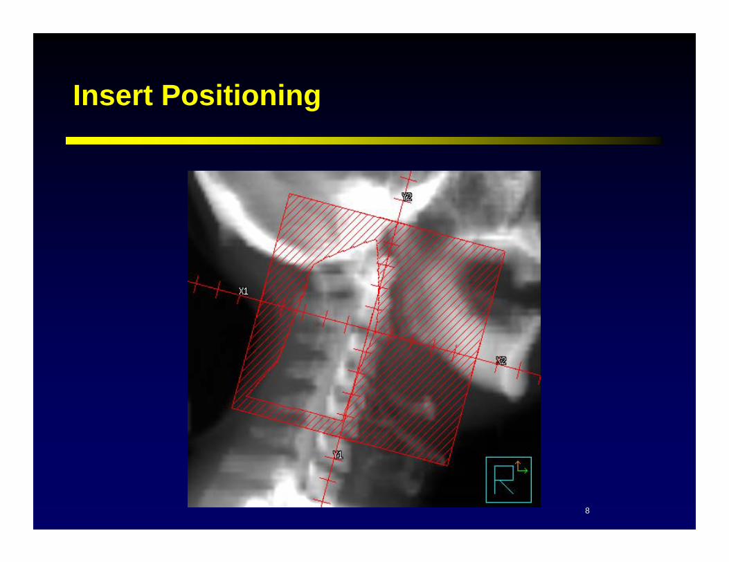
8
Insert Positioning

9
Parotid
• 46-year-old lady with T2, N0 mucoepidermoid carcinoma of the left parotid gland.
• 46-year-old lady with T2, N0 mucoepidermoid carcinoma of the left parotid gland.

10
No Bolus

11
Non-Beveled Bolus
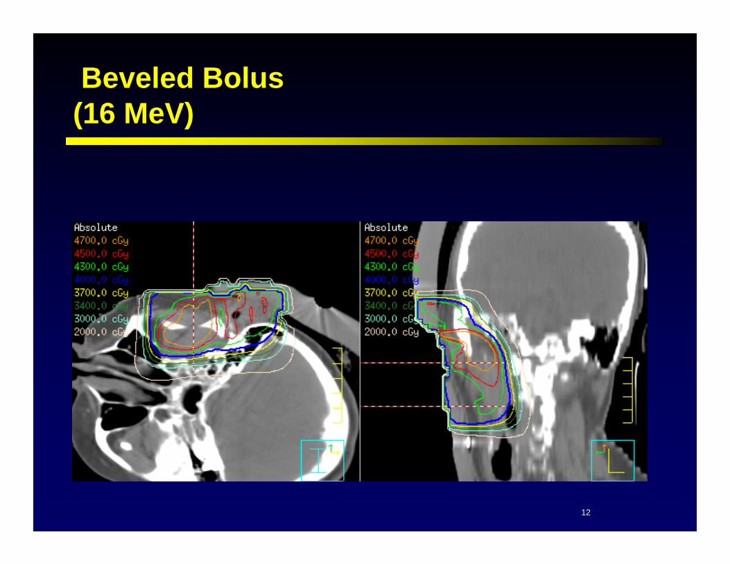
12
Beveled Bolus(16 MeV)

13
Pediatric CNS
• 3-year-old boy presented in fall of last year with tremors and found to have a large mass in the right parietal lobe with craniotomy. Biopsy confirming choroid plexus carcinoma. There is evidence of leptomeningeal disease both intracranially as well as in the spine.
• 3-year-old boy presented in fall of last year with tremors and found to have a large mass in the right parietal lobe with craniotomy. Biopsy confirming choroid plexus carcinoma. There is evidence of leptomeningeal disease both intracranially as well as in the spine.

14
Pediatric CNS(12 MeV)

15
Transverse CNS

16
Bi-Lateral Chestwall
• 70-year-old, postmenopausal female that had a left modified radical mastectomy in 07/01, and right modified radical mastectomy in 06/02 along with adjuvant chemo and radiotherapy.
• 70-year-old, postmenopausal female that had a left modified radical mastectomy in 07/01, and right modified radical mastectomy in 06/02 along with adjuvant chemo and radiotherapy.

17
Bi-Lat ChestWall Electron(5 & 7 MeV )

18
Bi-Lat Chestwall Skin Rendering

19
Intact Breast
• 54 years old and has a T1, N0 invasive carcinoma of the right breast which is ductal in origin, nuclear grade III. She underwent segmental mastectomy with negative sentinel node evaluation.
• 54 years old and has a T1, N0 invasive carcinoma of the right breast which is ductal in origin, nuclear grade III. She underwent segmental mastectomy with negative sentinel node evaluation.

20
Breast Boost(20 MeV)

21
Mesophelioma
• Extrapleural pneumonectomy (EPP) followed by RT• Heart, liver, lung, kidney, cord, esophagus• Extrapleural pneumonectomy (EPP) followed by RT• Heart, liver, lung, kidney, cord, esophagus

22
Mesothelioma
• 180cGy to 5400cGy• Abdomen block to shield
stomach and liver• Start heart block at
1980cGy• Block cord at 4140
• 180cGy to 5400cGy• Abdomen block to shield
stomach and liver• Start heart block at
1980cGy• Block cord at 4140

23
Why treat with electrons?
• Region of fairly uniform dose, then rapid falloff
• Treat superficial targets
• Avoid dose to deep and/or adjacent tissues
• Region of fairly uniform dose, then rapid falloff
• Treat superficial targets
• Avoid dose to deep and/or adjacent tissues

24
LINAC in e- Mode
• Scattering Foil
• Monitor ionization chambers
• Field defining Light
• Collimator System
– 2o e- collimation = cone,downstream of photon collimatorsplaced close to skin to dec. e- scatter in air
– 3o e- collimation = cutoutdownstream of conecustom shape field to match Rx site
• Scattering Foil
• Monitor ionization chambers
• Field defining Light
• Collimator System
– 2o e- collimation = cone,downstream of photon collimatorsplaced close to skin to dec. e- scatter in air
– 3o e- collimation = cutoutdownstream of conecustom shape field to match Rx site
Khan, Figure 4.8B

25
Electron scattering system

26
Electron Cones
• Always use a electron cone.• Always use a electron cone.

27
Electron Cones
• Available cone sizes for the Varian 21EX:– 6x6, 10x10, 15x15, 20x20,
25x25
• Available cone sizes for the Varian 21EX:– 6x6, 10x10, 15x15, 20x20,
25x25
20x20
15x15
6x610x10
25x25 (18lbs)
28
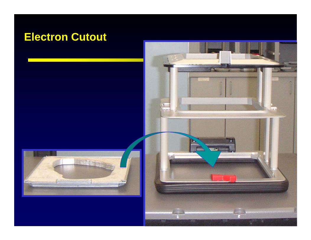
Electron Cutout

29
Electron Cutout
• Further field shaping with cut-out.
• Further field shaping with cut-out.

30
Cone Interlock
31
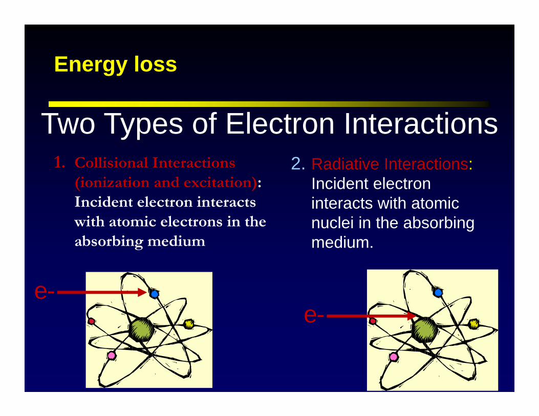
Energy loss
1. Collisional Interactions (ionization and excitation): Incident electron interacts with atomic electrons in the absorbing medium
2. Radiative Interactions:Incident electron interacts with atomic nuclei in the absorbing medium.
Two Types of Electron Interactions
e-e-

32
Electron Stopping Power Stopping Power - Energy lost per unit path
length in the medium MeV/cm Stopping power depends on the density of the
absorbing medium. Thus……
Mass Stopping Power = Stopping power divided by density MeVcm2/g
gMeVcm
gcm
cmMeVcm
MeV23
3cmg
33
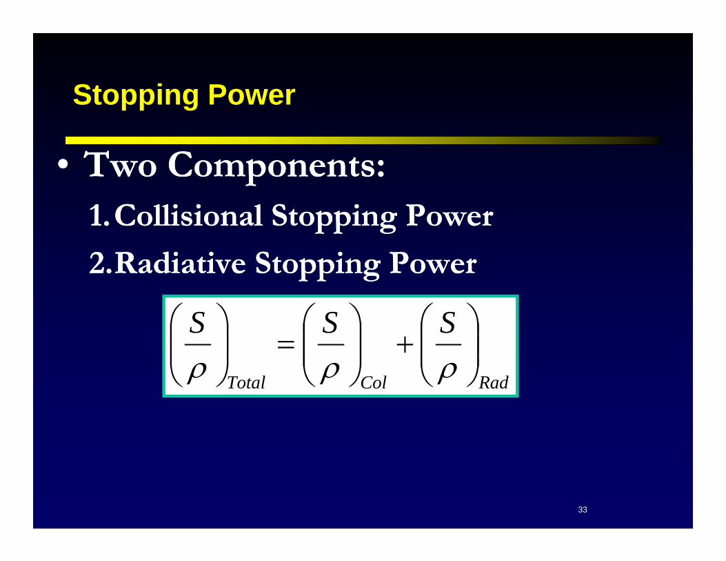
Stopping Power
• Two Components:1.Collisional Stopping Power
2.Radiative Stopping Power
• Two Components:1.Collisional Stopping Power
2.Radiative Stopping Power
RadColTotal
SSS

34
Khan, Figure 14.1
Collision Stopping Power: Tapers off with increasing energy
Higher for Lower Z
~2MeV/cm for water for E>1MeV
Radiative Stopping Power:
Large increase with increasing energy
Higher for higher Z
(Khan)

35
• Energy lost by a charged particle in a medium is not always equal to the energy absorbed in a target, especially when the target is small with respect to the range of secondary electrons produced, some of the secondary electrons (-Rays) do not deposit dose locally.
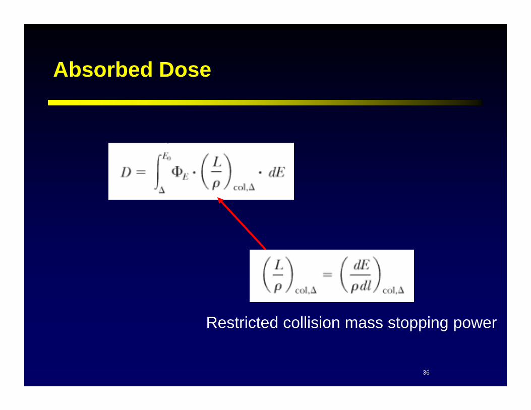
• Restricted Collisional Mass Stopping Power The energy (E) lost by an electron per unit path length (l) as a result of collision interactions with atomic electrons in which the energy loss is less than .
•Basically it is the collisional stopping power without the high energy -rays.
Restricted Collisional Mass Stopping Power
,, colcol ddEL
ICRU Nomenclature
36
Absorbed Dose
Restricted collision mass stopping power

37
Electron Scattering
• Multiple-coulomb scattering interactions between incident electrons and (mostly) nuclei of the medium
• Scattering power Z2E-2
• Multiple-coulomb scattering interactions between incident electrons and (mostly) nuclei of the medium
• Scattering power Z2E-2
From AAPM Summer School 1991

38
Effect of scattering on depth-dose curves
(2) + scatter
(3) + angle
(2) With scatter and angle
(3) Experimental

39
Characteristics of clinical electron beams
X-Ray Contamination
Surface
DoseDepth of
80% Dose
Depth of 90% Dose
40
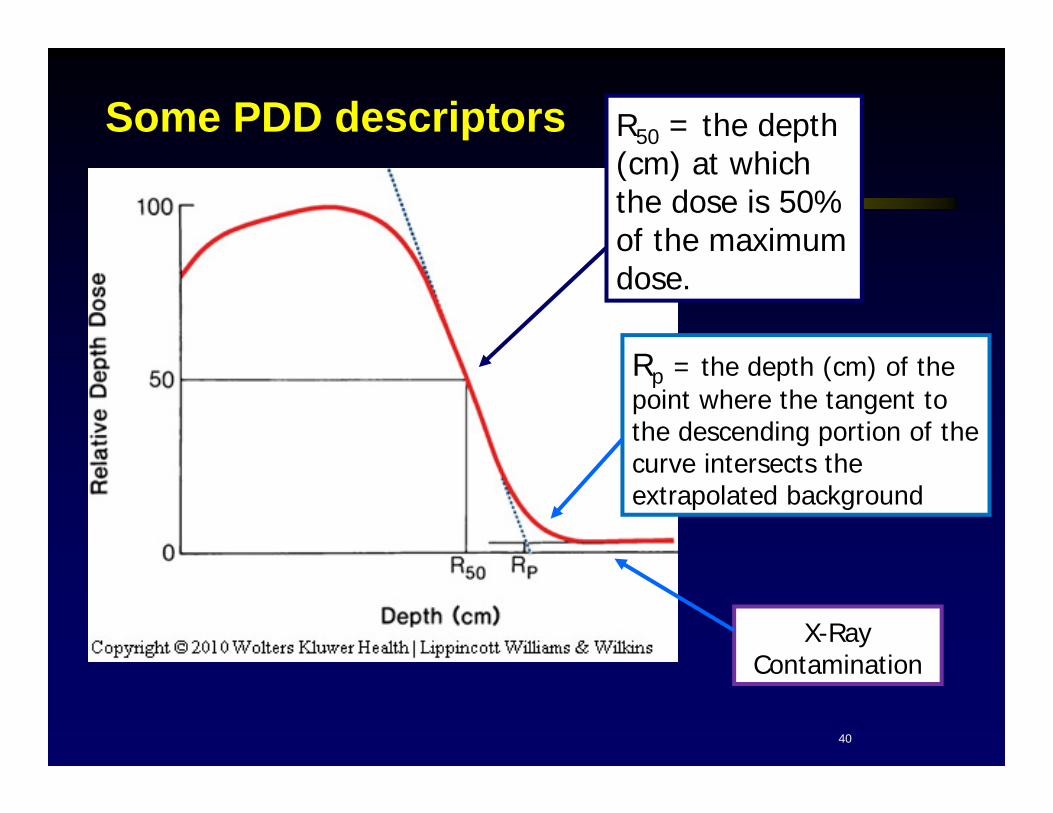
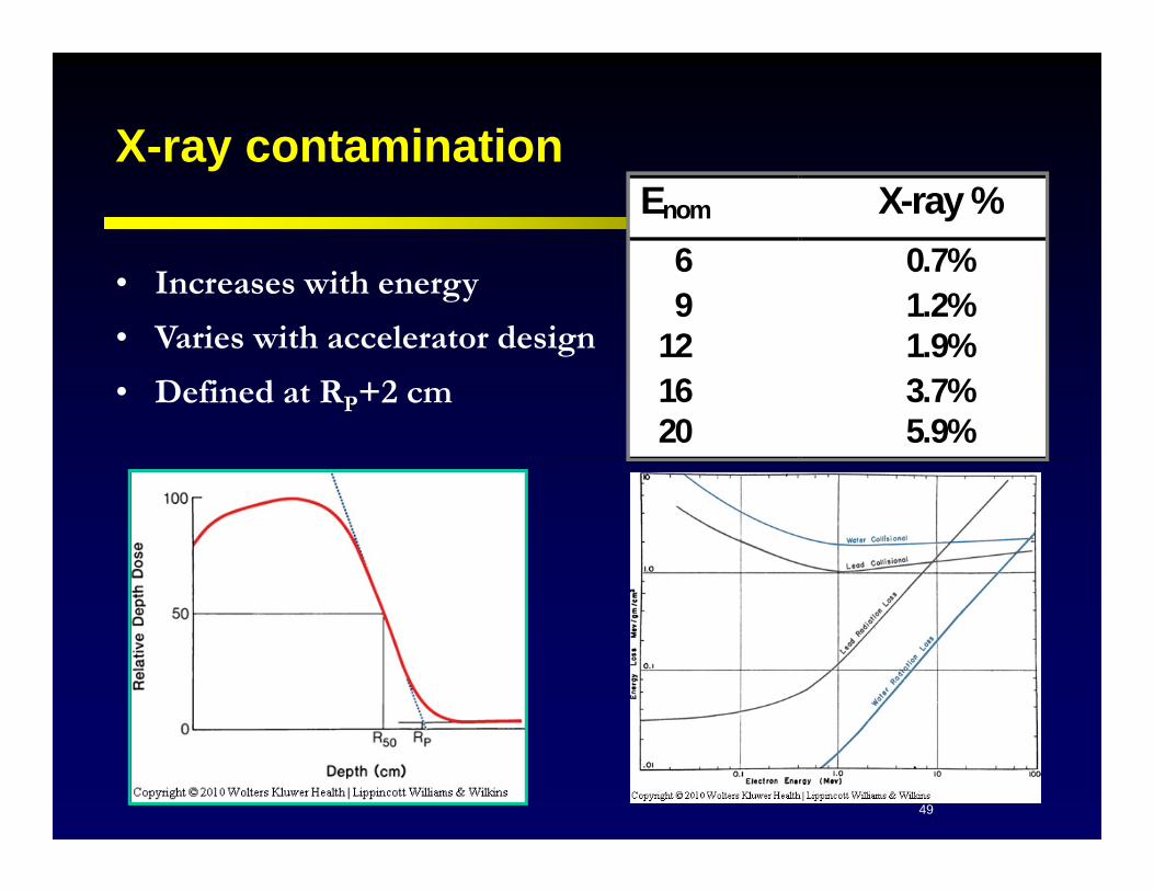
Rp = the depth (cm) of the point where the tangent to the descending portion of the curve intersects the extrapolated background
R50 = the depth (cm) at which the dose is 50% of the maximum dose.
X-Ray Contamination
Some PDD descriptors
41
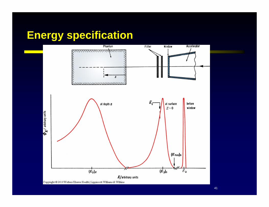
Energy specification

42
Mean Energy, E0
• The MEAN ENERGY of an electron beam, at the phantom surface is given by:
C4 as defined by TG21 is 2.33 MeV/cm
C4 according to more recent Monte-Carlo calculations is 2.4 MeV/cm
• The MEAN ENERGY of an electron beam, at the phantom surface is given by:
C4 as defined by TG21 is 2.33 MeV/cm
C4 according to more recent Monte-Carlo calculations is 2.4 MeV/cm
5040 RCE

43
Most probable energy
According to the Nordic Association of Medical Physics:
• C1=0.22 MeV
• C2=1.98 MeV cm-1
• C3=0.0025 MeV cm-2
• (in practice, OK to ignore beam divergence)
According to the Nordic Association of Medical Physics:
• C1=0.22 MeV
• C2=1.98 MeV cm-1
• C3=0.0025 MeV cm-2
• (in practice, OK to ignore beam divergence)

44
Energy at Depth, (Ep)z
pz R
zEE 10
Where:z is depth in tissue Rp is the practical range(same equation for (EP)Z
E0
Z
EZ

45
Characteristics of Clinical Electron Beams
• Depth of the 80% Dose:– Equal to approximately Enom/2.8 :
– Depth of 90% is approximately Enom/3.2
E n o m in a l E n o m / 2 .8 A c tu a l 6 2 .1 4 2 .2 0 9 3 .2 1 3 .3 0 1 2 4 .2 8 4 .3 0 1 6 5 .7 1 5 .5 0 2 0 7 .1 4 7 .0 0
MDACC 21EX
E n o m in a l E n o m / 3 .2 A c tu a l 6 1 .8 8 2 .0 0 9 2 .8 1 3 .0 0 1 2 3 .7 5 4 .0 0 1 6 5 .0 0 5 .0 0 2 0 6 .2 5 6 .1 0

46
Characteristics of clinical electron beams
• Practical Range:
– Equal to approximately 1/2 nominal energy:
– Energy loss is about 2 MeV / cm
E n o m i n a l E n o m / 2 R p 6 3 .0 3 .1 5 9 4 .5 4 .5 8 1 2 6 .0 6 .0 4 1 6 8 .0 7 .6 6 2 0 1 0 .0 1 0 . 1 3
MDACC 21EX
• Depth of maximum dose (R100):• For E<12MeV, R100 equal to approximately E/4• Remember PDD very flat for higher energy beams

47
Electron Depth Dose Curves: The approximate 4,3,2 rule of thumb
R80
80
R90 R80
90
R100 Rp
234
30
9080ER 2
0ERP 40
100ER

48
Entrance dose
• Surface dose increases with increasing energy– At lower energies electrons are
more easily scattered through larger angles.
• Surface dose increases with increasing energy– At lower energies electrons are
more easily scattered through larger angles.
Enom Surface dose (%)
6 72
9 78
12 83
15 87
18 91
49
X-ray contaminationEnom X-ray % 6 0.7% 9 1.2% 12 1.9% 16 3.7% 20 5.9%
Enom X-ray % 6 0.7% 9 1.2% 12 1.9% 16 3.7% 20 5.9%
• Increases with energy
• Varies with accelerator design
• Defined at RP+2 cm

50
Khan, figure 14.1

51
Raphex Question: T64-67, 2003
A. 6MeV
B. 9MeV
C. 12MeV
D. 16MeV
E. 20MeV
T64. Has Highest Surface Dose.
T65. Has Range of 6cm in tissue.
T66. Has 90%dd at 2.7cm.
T67. Has sharpest falloff between 80% and 20%.
Bonus: Has highest dose beyond the practical range
• Match the electron energy with the feature described below:

52
Raphex Question: T54, 1999
• An electron beam of how many MeV would be most suitable to treat a volume extending to a depth of 3cm of area 10x10cm?
A. 3B. 6C. 10D. 15E. 20
• An electron beam of how many MeV would be most suitable to treat a volume extending to a depth of 3cm of area 10x10cm?
A. 3B. 6C. 10D. 15E. 20

53
Raphex Question: T46, 2001
• Compared with 6MeV electrons, 16MeV electrons have:
a) A greater surface dose.b) A lower bremsstrahlung tail.c) A sharper fall-off between 80% and 20%
isodose levels
• Compared with 6MeV electrons, 16MeV electrons have:
a) A greater surface dose.b) A lower bremsstrahlung tail.c) A sharper fall-off between 80% and 20%
isodose levels

54
Raphex Question: T58, 2002
A. Is about the same as that of a photon beam with the same energy
B. Is lower for a beam with a scattering foil than for a scanned beam.
C. Is about the same as that of a superficial x-ray beam.
D. Increases as energy increases
A. Is about the same as that of a photon beam with the same energy
B. Is lower for a beam with a scattering foil than for a scanned beam.
C. Is about the same as that of a superficial x-ray beam.
D. Increases as energy increases
• Which of the following is true regarding electron beams? The surface dose:
55
Raphex Question: T68, 2003
• The dose beyond the practical range is primarily due to:
A. Very low energy electrons.
B. The highest energy electrons in the spectrum.
C. Characteristic x-rays generated in tissue.
D. Bremsstrahlung.
• The dose beyond the practical range is primarily due to:
A. Very low energy electrons.
B. The highest energy electrons in the spectrum.
C. Characteristic x-rays generated in tissue.
D. Bremsstrahlung.

56
What energies do you think we might use?
(a) (b)
Choice: 6, 9, 12, 15, 18MeVBolus or no bolus?

57
Electron Isodose Curves
• Isodose Curves – Scattering of electrons very important factor in SHAPE of isodose curve.
• As the beam penetrates the medium, the beam expands rapidly below the surface due to scattering!
• Spread of isodose curve depends on:1. Isodose Level2. Energy3. Field Size 4. Collimation

58
Electron Isodose Curves
Low Energy Electron Beams
• ALL isodose levels bulge out!
High Energy Electron Beams• LOW isodose levels bulge out• HIGH isodose levels show lateral
constriction, which becomes worse with decreasing field size
7 MeV 18 MeV

59
External electron shielding
2MeVEmm o
Pb
• Thickness of shielding should give < 5% transmission. – If weight or thickness no problem, can use more than
minimum required.• When placing shields directly on patient use minimum
thickness to achieve desired reduction in dose.– Eye shields– Internal shields
• Rule of Thumb: Minimum thickness of Pb for blocking electrons in mm is given by electron energy INCIDENT in the lead divided by 2.

60
Internal Shielding
• Internal shielding can be useful to protect structures beyond target volume.
• Commonly used for:– Buccal mucosa, lip, eye lid lesions.
• Electron backscatter from the lead can enhance dose near the shield.– Magnitude of the Increase: 30-70% in the range of 1 to 20
MeV, having higher value for lower energies.

61
Internal Shielding
• Electron back scatter Factor (EBF) – The quotient of dose at interface with lead in place to that with homogeneous polystyrene phantom at the same point
where,
• Electron back scatter Factor (EBF) – The quotient of dose at interface with lead in place to that with homogeneous polystyrene phantom at the same point
where,
pz R
zEE 10
)052.0(735.01 zEeEBF

62
Internal Shielding
• To dissipate the effect of elect of electron backscatter from Pb shield, place suitable amount of low Z absorber between lead shield and preceding tissue interface.
• Typically want to reduce transmission of the backscattered electron intensity to ≤10%.
• To dissipate the effect of elect of electron backscatter from Pb shield, place suitable amount of low Z absorber between lead shield and preceding tissue interface.
• Typically want to reduce transmission of the backscattered electron intensity to ≤10%.
Thickness of Low Z (=1) material required to absorb the backscattered electrons is determined using the data in the figure below:
Khan, Figure 14.40

63
Internal Shielding Example:
• A buccal mucosa lesion is treated with a 9MeV electron beam incident externally on the cheek.
• Assuming the thickness of the lesion is 2cm, calculate:
a) The thickness of lead required to shield the oral structures beyond the cheek.
b) Magnitude of electron backscatter.
c) Thickness of bolus or Al to absorb the backscattered electrons.

64
Internal Shielding Example:
a. The thickness of lead required to shield the oral structures beyond the cheek. Incident Energy = 9MeV
Need to calculate energy at depth = 2cm
Recall: Rule of Thumb: Minimum thickness of Pb for blocking electrons in mm is given by electron energy INCIDENT in the lead divided by 2.
a. The thickness of lead required to shield the oral structures beyond the cheek. Incident Energy = 9MeV
Need to calculate energy at depth = 2cm
Recall: Rule of Thumb: Minimum thickness of Pb for blocking electrons in mm is given by electron energy INCIDENT in the lead divided by 2.
MeVRzEE
pz 5
5.421910
5.225Pbmm

65
Internal Shielding Example:
b. Magnitude of electron backscatter.
The lead shield causes a 57% increase in dose at the tissue interface.
b. Magnitude of electron backscatter.
The lead shield causes a 57% increase in dose at the tissue interface.
)052.0(735.01 zEeEBF
57.1735.01 )5052.0( MeVeEBF

66
Internal Shielding Example:
c. Thickness of bolus or Al to absorb the backscattered electrons.
c. Thickness of bolus or Al to absorb the backscattered electrons.
From Figure 14.40, a 5MeV beam 10mm of polystyrene or bolusrequired to reduce the transmission of backscattered electrons to 10% transmission. Using equation
AltAl=bolustbolus, the equivalent amount of Al is 4mm (AL=2.7g/cm3)
Khan, Figure 14.40

67
Raphex Question: T70, 2003
• The thickness of lead required to shield a 6MeV electron beam is approximately___mm.
A. 0.5
B. 3
C. 6
D. 12
E. 24
• The thickness of lead required to shield a 6MeV electron beam is approximately___mm.
A. 0.5
B. 3
C. 6
D. 12
E. 24

68
Problems of Adjacent Electron Fields
• Adjacent Electron Fields– Abutting at surface – Hot spots in junction region.
– Separated at surface – Cold spots in junction region.
• Electrons are typically used to treat lesions close to skin surface.– Hot spot may be more acceptable than cold spot.
• Adjacent Electron Fields– Abutting at surface – Hot spots in junction region.
– Separated at surface – Cold spots in junction region.
• Electrons are typically used to treat lesions close to skin surface.– Hot spot may be more acceptable than cold spot.

69
Problems of Adjacent Electron Fields
• Adjacent electron Fields with different gaps at surface.
• As gap decreases from 1.5cm to 0.5cm, cold spot is reduced, but hot spot is increased.
• Adjacent electron Fields with different gaps at surface.
• As gap decreases from 1.5cm to 0.5cm, cold spot is reduced, but hot spot is increased.
Khan, Figure 14.30

70
Problems of Adjacent Electron/Photon Fields
• Adjacent Electron/Photon Fields– Hot spot on Photon side
– Cold spot on electron side
• The extent of the hot and cold spots depends on the electron beam SSD– When SSD is increased:
• Electron profile becomes less flat as a result of increased electron scattering by air.
• Hot and Cold spots spread out over larger areas without large change in magnitude.
Due to outscattering of electrons from electron field.

71
Adjacent Electron/Photon Fields
• Adjacent Electron/photon fields.A. SSD = 100
B. SSD = 120
• Adjacent Electron/photon fields.A. SSD = 100
B. SSD = 120
Hot/cold spot covers larger area when electron field at extended SSD.

72
Raphex Question: T59, 2002
• Regarding electron field junctions, which of the following is true? When the light fields of two adjacent electron fields are matched on the skin:
A. The dose variation across the junction will be within 5% if the electrons have the same energy and light fields abut.
B. There will always be hot and cold spots because of the shape of electron penumbra.
C. The formula: gap=(depth/sad)x(C1+C2)/2 gives the best match.
D. Overlapping the fields by 0.5 cm generally gives the best match.

73
Effect of Oblique Incidence on Dose Distribution
• The broad electron beam can be represented as a large number of pencil beams placed adjacent to each other.
When a beam is obliquely incident on the patient’s surface:– Points at shallow depths receive greater
side scatter from adjacent pencil beams, which have traversed a greater amount of the material.
– Points at greater depths receive less scatter.

74
Effect of Oblique Incidence on Dose Distribution
• Increased dose at shallow depths
• Decreased dose at deeper depths
• In Reality as obliquity increases, the air gap between the skin surface and the cone end increases.
• The depth dose at a point in an obliquely incident beam is effected by both “pencil scatter effect” and “beam divergence”.
• Increased dose at shallow depths
• Decreased dose at deeper depths
• In Reality as obliquity increases, the air gap between the skin surface and the cone end increases.
• The depth dose at a point in an obliquely incident beam is effected by both “pencil scatter effect” and “beam divergence”.
Expected consequence of
oblique incidence

75

76
Surface Irregularities
Hot
Spot
Hot
Spot
Khan14.23
Hot
Spot
Hot
Spot
Hot
Spot
Hot
Spot

77
Raphex Question: T59, 1999
• An electron enters a patient’s surface obliquely. If the MU are calculated for normal incidence, ALL of the following can be expected EXCEPT:
A. Surface dose increases.B. Depth of dmax decreases.C. Depth of 90% isodose decreases.D. Depth of 50% isodose increases.
• An electron enters a patient’s surface obliquely. If the MU are calculated for normal incidence, ALL of the following can be expected EXCEPT:
A. Surface dose increases.B. Depth of dmax decreases.C. Depth of 90% isodose decreases.D. Depth of 50% isodose increases.

78
Raphex Question: T61, 1999
• When treating with high energy electron beams, one of the problems with using bolus over part of the field is:
A. Calculating the thickness necessary.B. Finding an appropriate material.C. Dose inhomogeneity at the edge of the bolus.D. The production of Bremsstrahlung.
• When treating with high energy electron beams, one of the problems with using bolus over part of the field is:
A. Calculating the thickness necessary.B. Finding an appropriate material.C. Dose inhomogeneity at the edge of the bolus.D. The production of Bremsstrahlung.

79
Output – effect of field size
80
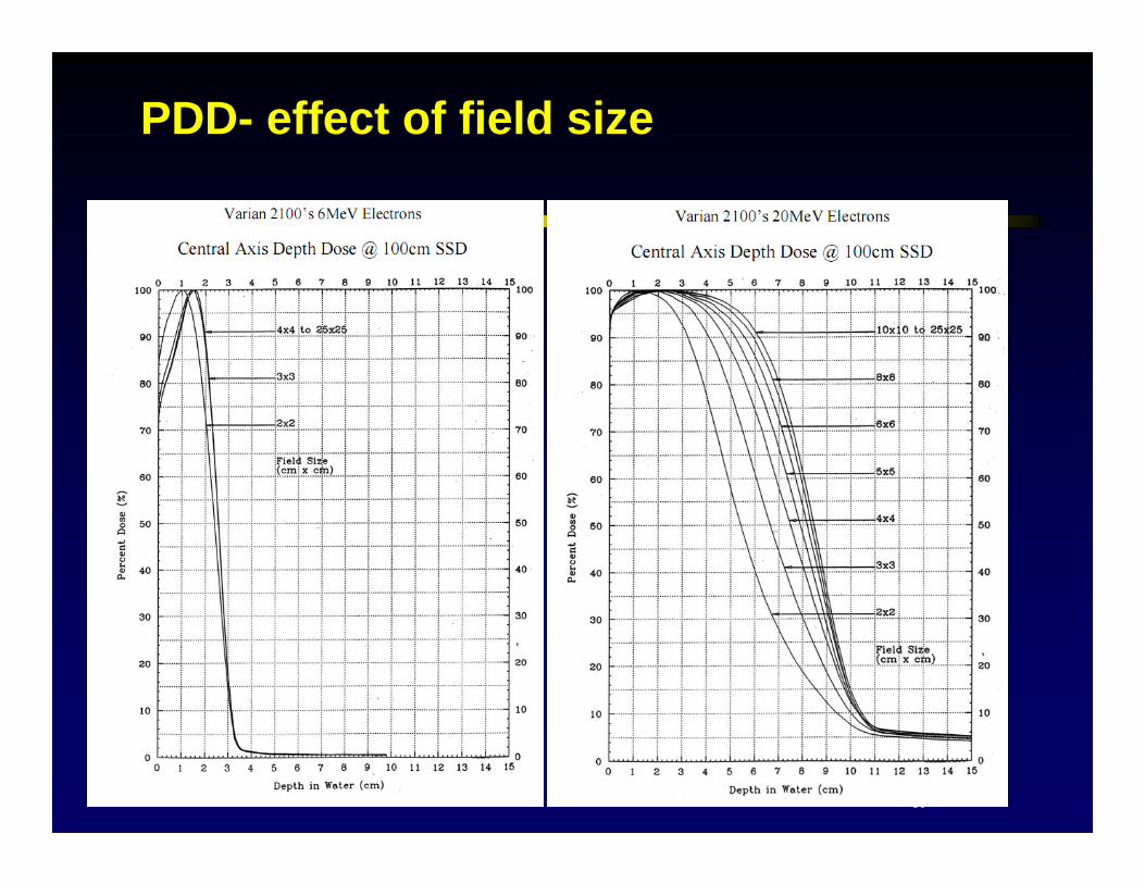
PDD- effect of field size

81
How small can I make a field?
• If a field produced by a lead cutout is smaller than the minimum size required for maximum lateral dose build-up, dose in open portion is reduced.
• The ICRU suggested Rp as the lower limit for field diameter. – Lateral scatter equilibrium is achieved if field size created by the
cutout is > Rp (E/2).• Khan showed lateral scatter equilabrium is achieved if
Req>0.88Ep,0
Should be > E/2
(will talk about square vs circle later)

82
Raphex Question: T60, 2002
• Electron output (cGy/MU) depends on all of the following EXCEPT:
A. Cone or applicator size.B. SSD.C. Size of custom insert.D. Dose Rate at dmax
• Electron output (cGy/MU) depends on all of the following EXCEPT:
A. Cone or applicator size.B. SSD.C. Size of custom insert.D. Dose Rate at dmax
83
Raphex Question: T69, 2003
• When a custom electron insert has dimensions smaller than the range of the electrons, all of the following are likely to occur except:
A. The output (cGy/MU) will be reducedB. Surface dose will decrease.C. PDD will decrease beyond dmax.D. Dmax will shift toward a shallower depth.
• When a custom electron insert has dimensions smaller than the range of the electrons, all of the following are likely to occur except:
A. The output (cGy/MU) will be reducedB. Surface dose will decrease.C. PDD will decrease beyond dmax.D. Dmax will shift toward a shallower depth.

84
Characteristics of clinical electron beams
X-Ray Contamination
Surface
DoseDepth of
80% Dose
Depth of 90% Dose
Thank you!