electron-retracts products manual
TRANSCRIPT

ELECTRON-RETRACTS PRODUCTS MANUAL

CONTENT
0 - INTRODUCTION TO ELECTRON RETRACTS
0A - GENERAL WARNINGS
0B - GLOSSARY OF TERMS
1 - CONTROLLERS Introduction and models available
1A - MANUAL CONTROLLER
1A.1 - Technical specifications and features
1A.2 - Installation and connections
1A.3 - Power supply
1A.4 – Setup
1B - RB-45 CONTROLLER
1B.1 - Technical specifications and features
1B.2 - Installation and connections
1B.3 - Power supply
1B.4 - Programming
1B.5 - Wiring diagram
1C - RS-200 CONTROLLER
1C.1 - Technical specifications and features
1C.2 - Installation and connections
1C.3 - Power supply
1C.4 - Programming
1C.5 - Wiring diagram
1D - GS-200 CONTROLLER
1D.1 - Technical specifications and features
1D.2 - Installation and connections
1D.3 - Power supply
1D.4 - Programming
1D.5 - Wiring diagram
1E - E-BRAKE
1E.1 - Technical specifications and features
1E.2 - Installation and connections
1E.3 - Power supply
1E.4 - Programming
2 – MECANISMS
2A - RETRACTS Introduction and models available
2A.1 - Technical specifications and features
2A.2 - Installation and connections
2A.3 - Power supply
2A.4 - Use and warnings
2A.5 - Maintenance and breakdown
2A.6 - Interchangeable Trunion
2B - STEERING MECANISMS

3 - STRUTS
3.1 - Technical specifications and features
3.2 - Installation and connections
4 - BRAKES Introduction and models available
4.1 - Technical specifications and features
4.2 - Installation and connections
4.3 - Problems and solutions
5 – LINEAR ACTUATOR
5.1 Technical specifications and features
5.2 Installation and connections
5.3 Power supply
5.4 Programming
6 - YOUTUBE
7 – TERMS & CONDITIONS

0 - INTRODUCTION TO ELECTRON RETRACTS
Thank you choosing to purchase Electron Retracts.
Retracts are a mechanically complex system, needing to be capable of supporting high loads while working in a dusty
environment, with little to no maintenance, all without fail.
Electron Retracts came to life to cover all of these requirements, without the usual headache caused by the previously industry
standard air systems with their constant leeks and shortcomings, while also providing our clients with the worlds most technically
advanced retract system, produced to the highest standards of manufacturing, quality and reliability.
Since 2007, Electron Retracts has been dedicated to the design, development and production of completely electric retract
systems which guarantee as much as possible the correct retraction and extension of retracts in all kinds of models.
The Electron Retracts team is comprised of leading RC pilots as well as electronics experts and top CAD/CAM operators.
Thanks to this tight collaboration, we have been able to develop a system that is highly reliable, compact, long wearing, easy to
handle and easy to maintain.
0A - GENERAL WARNINGS
- Never apply power directly to the Retracts! Always use a controller. The use of a battery direct to the Retract will destroy the
unit.
- Never join multiple wires through a single connection or pin. The negative leads from the Retracts and the Brakes are not
common and will therefore destroy the system if joined together.
- Never us Emcotec "MultiPin Connectors" for your wing connections. These connectors join multiple wires through a single pin
and will as such destroy your controller immediately when connected.
- Never apply power to the system without having previously read the instructions for your chosen Controller.
- Never connect the Retracts directly to a receiver, this will destroy your receiver irreversibly.
- Always verify that the voltage and polarity of your power supply are correct and appropriate for your chosen Controller.
- Always disconnect all batteries from your model prior to charging. Due to internal permanent connections between the
Controller and the Receiver, charging more than one battery at once without prior disconnection can cause irreversible damages.
Do not mix components from Electron Retracts with other brands
Never connect other brand components to Electron Retract components. Each Retract has a very specific motor and the Controller
needs to be programmed for its appropriate parameters. A mismatch can result in the motor, electronics or both being damaged
irreversibly.
Do not swap controllers, even within the Electron Retract brand.
Do not swap the controllers between Retract combos. As stated above, each motor has very specific parameters required to work
correctly. As such a Controller that is set up to work with say an ER-50 should not be used to operate an ER-40 or ER-30. Not
following this precaution can result in irreversible damage.
If you already own an Electron Retracts Controller and wish to use it on a different Retract set to that it came with, please contact
with your local dealer to arrange for the software parameters to be updated.

0B - GLOSSARY OF TERMS:
In this manual you will find certain terminology. To facilitate a correct understanding of the contents, please review the following
glossary of terms before starting:
Components: -Controller: The Controller refers to the small electronics box that controls the retracts, brakes, gear doors, etc... Currently available are the RB-45, RS-200, GS-200 and the E-Brake.
-Powerbox: Refers to the models receiver and power distribution unit. Not to be confused with the Electron Retract Controllers.
-Retract: We use the term Retract to refer to the entire mechanical unit comprised of motor, frame, spindle and trunnion that perform the actions of retracting or extending the landing gear. Currently available are the ER30EVo, ER40EVo & ER50EVo.
-Frame: This is the cage type structure, milled from a single block of aeronautic aluminum 7075-T6 which has been anodized black and engraved with the serial number. This part is where all other components that make up the Retract are housed.
-Trunnion: The Trunnion is the part that is still of aluminum color (natural anodizing) located at the center of the Frame. It rotates from a single pivot point and is attached directly to the retract leg. It is the component that actually performs the movement of extending or retracting the landing gear. Depending on how much rotation you require for your specific model, different Trunnions can be mounted with greater or lesser angles of rotation.
-Spindle: This is the threaded rod found at the center of the Frame. It has a special square thread which allows for increased power and speed to the entire system.
-Slider: As its name indicated, when the motor turn the spindle, the Slider is the part which actually moves along the rails of the Frame, pushing the Trunnion to extend or retract the landing gear.
-Gearbox: The Retract has a small gearbox located between the motor and the spindle.
-Strut: The Strut is the landing gear leg. It's connected to the trunnion with a steel pin. The wheel and the brake are attached at the other end of the strut.
-Simple Pull-Pull, Coupling System, Servo Plate and Inverted Steering: These are the four kinds of steering systems that are available for our nose wheel setups. For a full description, please see section 2B of this manual.
Concepts:
-Single Channel Operation: This option allows you to use a single channel to control both the retracts and the brakes, rather than one channel for each function.
This works in a similar way to a turbine, where the trim is used to start or stop the turbine, while power is controlled by the stick. For example, you can program the channel to use from -100% to -75% to control the retracted or extended position of the retracts, and then from -75% to +100% to control the power applied to the brakes.
-PWM: This is the traditional method of connecting two electronic components, by means of leads. In our case, connecting the Controller to the receiver/powerbox, using one lead per channel (one for retracts, one for brake and one for steering)
-BUS: This is the other method of connecting two electronic components, by means of a single lead. In our case, the receiver/powerbox would send all the information for the retracts, brakes, steering through a single wire.
-Offset: We use this term to describe the distance from the centerline of the strut, to the center of the wheel axel. Adjustments can be made at any time to the strut to change the offset. The nose strut doesn’t have adjustable offset.
-TxGear: We use this term to describe the channel or switch on the transmitter used to control the retracts.
-TxGearUp / TxGearDown: We use these terms to indicate the position of the transmitter switch for the gear. Be it in the Gear Up position or Gear Down position.
-TxBrake: We use this term to describe the channel or switch on the transmitter used to control the brakes.
-TxRudder: We use this term to describe the channel or stick on the transmitter used to control the nose wheel steering (can be the same as rudder channel or a separate channel).
-RxGear: Refers to the port in the receiver or powerbox from which we will take the signal for the Gear channel for our Controller.
-RxBrake: Refers to the port in the receiver or powerbox from which we will take the signal for the Brake channel for our Controller.
-RxRudder: Refers to the port in the receiver or powerbox from which we will take the signal for the nose wheel steering channel for our Controller.
-SxSteering: Refers to the servo used to control the steering of the nose wheel.
-Actuator: We will use the term Actuator to describe the mechanical component used to move any gear doors, regardless of them being Electron Retract Linear Actuators, servos or electro valves with pneumatic pistons.

1 - CONTROLLERS
Electron Retracts controllers are designed to work perfectly in conjunction with our Retracts and Brakes. Depending on the
Controller model, these offer options such door sequences or gyro assisted steering to guarantee a straight take off and braking.
Currently three versions are available, the RB-45 which includes all the basic functions required for Retracts, fully proportional
Brakes and steering, the RS-200 which adds optional ABS braking and a 3 gear door sequencer, or the GS-200 which in addition to
its large touch screen adds optional ABS, 8 gear door sequencer, internal gyro and optional independent braking linked to steering.
The Manual Controller is simple but useful support controller that allows to handle the retracts safely without having to turn on
the radio and model. This device is not intended for installation inside the model.
Also available is the small E-Brake Controller, which can be installed if your model only requires Brakes and not Retracts.
For all of the above, power should be supplied via an external battery with MPX connector, and be independent to the rest of your
models electrical system.
Each pole (+ and -) on the MPX uses all three pins from that side of the connector. A single 500mAh battery is more than enough
to last a full day flying without concern.
Pay special attention when soldering your connector that correct polarity is maintained.
Reversing the connections will cause irreversible damage to your controller.

1A - MANUAL CONTROLLER
1A.1 - Technical specifications and features
Dimensions: 47 x 36 x 15 mm
Weight: 45 g
Input voltage: See voltage accepted and required by your Retract. The controller can withstand up to 13v (3s Lipo)
Programming: Integrated buttons
Controls: Retracts
1A.2 - Installation and connections
Since you should never power a Retract unit with a direct power supply, as this will irreversibly damage the Retract, we created
the Manual Controller. This controller is not intended to be installed in a model, instead it is used when you wish to simply operate
a Retract without having to turn radio and model on.
Connecting the Retracts:
Only one Retract can be controlled at once. Simply connect the Retract to the single output on the Controller.
1A.3 – Power supply
Power should be provided from a Lipo battery with MPX type connector. Each pole (+ and -) on the MPX uses all three pins from
that side of the connector.
¡Warning!
Check for correct polarity before connecting the battery. Correct polarity is clearly marked
on the Controller with "Battery +" and "Battery - “.
Connection of a battery with reverse polarity will destroy the unit beyond repair.
The voltage to be used depends on which Retract size you will be controlling and
oscillates between a 2s and 3s Lipo. Please see the Retract Voltage table found
in section 2 of this manual as the wrong battery choice will result in an irregular
operation as well as damage to the same.
Read all warnings found in section 0A - WARNINGS before connecting a battery.

1A.4 - Setup
Firstly, confirm exactly what battery you need to use b ased on the size of Retract to be connected.
On the Controller itself there are three drawings indicating in what position the two small switches need to be in for
each Retract size, be it ER30, ER40 or ER50. The switches need to match the white indications on the drawing.
Once the correct switch positions have been chosen, the controller will cut off power to the Retract at the appropriate
amperage to assure a correct and safe operation specific to the size of Retract used.
Use:
With everything correctly connected, we can "Retract" or "Deploy" the Retract by simply pressing the according
button.
The Retract can be left at a interim position between fully retracted or fully deployed by simply releasing the button at
any point.
Once the Retract reaches one of its end positions, it will stop safely and without risk of damage to the unit. When this
happens, release the button for safety, since a wrong setup could damage the retract.
Video manual: https://www.youtube.com/watch?v=noqDhhSgBNc

1B - CONTROLLER RB-45
1B.1 - Technical specifications and features
Dimensions: 55 x 30 x 15 mm
Weight: 25 g
Input voltage: See voltage accepted and required by your Retract. The controller can withstand up to 13v (3s Lipo)
Programming: Via the integrated button
Controls: Retracts, proportional brakes and steering servo
Maximun current per output
2.5 A
1B.2 - Installation and connections
Due to its small size and light weight, the unit can be installed in any location of your model. We recommend installing in the
location that will allow for the shortest connections to the Retracts and Brakes.
The connections can be as long as required. If extensions wires are needed, use high quality wires, with similar section as the ones
provided, to avoid voltage drops.
Connecting the Radio (radio inputs):
Connect the RxGear to the Controllers "Gear in" input, the RxBrake to the "Brake in" input and the RxRudder to the
“Steering in” input
Please note! We recommend to always pass the RxSteering channel through the Controller.
This guarantees that the steering servo remains centred and blocked when the retracts are in
their retracted position and whilst the retracts are in movement; this is especially important if
using the Coupling System for steering. Additionally, this also simplifies the radio setup as it’s
not necessary to create special mixes to prevent the steering servo from moving whilst the
gear is up as everything is done by the Controller.
Connecting the Retracts:Connect the Retracts to the outputs on the Controller, marked as Nose G., Main L and Main R. The
polarity of the connector is indicated on the Controller.
Connecting the Brakes:
Connect the Brakes to the two outputs on the Controller marked "Brakes". The brakes do not have polarity, therefore the wires
can be connected both ways. Only the external pins are used for the brakes, the central pin is not used.
Connecting the Steering Servo: Connect the Steering Servo to the outputs on the Controller marked "Rudder servo”.

1B.3 – Power supply
Power should be provided from a LiPo battery with MPX type connector, separate to the rest of the models electrical system. This
battery will provide power to the Retracts and the Brakes. (be especially careful when soldering the connector to assure correct
polarity) Each pole (+ and -) on the MPX uses all three pins from that side of the connector. A 500mAh capacity battery is more
than enough for a complete flying day.
¡Warning!
Check for correct polarity before connecting the battery. Correct polarity is clearly marked
on the Controller with "Battery +" and "Battery - “.
Connection of a battery with reverse polarity will destroy the unit beyond repair.
The voltage to be used depends on which Retract size you will be controlling and
oscillates between a 2s and 3s Lipo. Please see the Retract Voltage table found
in section 2 of this manual as the wrong battery choice will result in an irregular
operation as well as damage to the same.
Read all warnings found in section 0A - WARNINGS before connecting a battery.
The Controller has an internal automatic switch on the GEAR IN input, which turns the controller off when no signal/power is
received. Thus, there is no need to disconnect the battery from the controller between flights. However, it is recommended to
disconnect the battery after the flying day as ended, as there is a small drain of power even when the retracts are not used.
Leaving the battery connected will empty them after a few weeks.
Please note! The following applies if you are using voltage regulators, power distribution board or
Retracts running from a 3s Lipo:
Regardless of the battery voltage used to power the Retracts, be it 2s or 3s, the steering servo will
receive the same power as the receiver/powerbox, via the "Gear in" input on the Controller. As
such, if the Controller is connected to the receiver and this is set to 5.9v, this is the voltage that
the steering servo will receive, regardless of what the battery that is powering the Retracts.
It is also important that the voltages that the Controller receives from "Gear in" and "Brake in"
are the same, as internally they are connected and using different voltages on these two inputs
can cause the unit not to function correctly. If you need to draw these two channels signals from
different power sources (one from a receiver at 5.9v and one from the powerbox at 7.4v)
simply remove (disconnect)the red wire (positive) from the connector which has the voltage
that you don't want to reach the steering servo.

1B.4 - Programming
We recommend performing all the programming with the battery disconnected. Just connect the three patch leads
between receiver and the controller.
Before starting, make sure that none of the channels that will be used for the Gear, Brakes and Steering are limited, and
have +100% to -100% throw, otherwise the programming may be unsuccessful.
1- With all the inputs turned off / NOT powered, press and hold the button/LED on the controller, and then turn the
model on.
Once the model is ON, wait 1-2 seconds and release the button/LED. The LED will start flashing. This indicates that the
Programming Setup has been started.
2- The first step is to program the TxGearUp position. Simply place the TxGear switch in the GearUp position and press
the button/led. The LED will do a sequence of two flashes.
3- Now to program the TxGearDown position. Like before, just place the TxGear switch in the GearDown position and
press the button/led. The led will now start a sequence of three flashes, and we can proceed to program the brakes.
If your model does not have magnetic brakes, you can skip the next two steps simply by pressing the button/led a further
two times.
4- Place the TxBrakes switch in the position with minimum brake power / where you want the brakes to start working,
and press the button/led, which will start a sequence of 4 flashes.
5- Increase the TxBrakes switch to the position where you want the brakes to have their maximum brake power, and
press the button/led, which will start a sequence of 5 flashes.
If sharing the elevator stick for Brakes, it is recommendable to use only the final third of the stick travel to work the brakes.
This will assure that the brakes are not activated in its neutral position, thus saving battery power.
6- The last step is to program the center position of the steering servo. To do this, we will use the TxRudder stick. Move
the stick until the steerring arm is in the center position and press the button/LED again. This finishes the Programming
setup and the LED will stop flashing.
Please notice! If you have the Coupling System in your retracts (Electron Steering System),
it's extremely important that the center position is accurate as possible,
to ensure a correct coupling of the steering system.

1B.5 - Wiring diagram:

1C - CONTROLLER RS-200
1C.1 - Technical specifications and features
Dimensions: 55 x 30 x 15 mm
Weight: 25g
Input voltage: See voltage accepted and required by your Retract. The controller can withstand up to 13v (3s Lipo)
Programming: Via the integrated led/button or via Data Terminal (data terminal: Electron Retracts Programmer)
Controls: Retracts, proportional brakes with optional ABS, steering servo and three gear doors (some options require the use of the Electron Retracts Programmer - see section 1C.4)
Features: -Normal mode (one channel for gear and one channel for brakes) or Single Channel operation (use of a single channel to control both retracts and brakes) -Programmable delay for the retraction and extention of each of the Retracts independantly -Programmable delay and travel of the gear doors (sequencer) -Programmable ABS braking -Easy programming via the Electron Retracts Programmer LED screen
1C.2 - Installation and connections
Due to its small size and light weight, the unit can be installed in any location of your model. We recommend installing in the
location that will allow for the shortest connections to the Retracts and Brakes.
The connections can be extended as required providing that it is extended by wires of a similar high quality and section as those
provided to assure no voltage drop occurs in the long leads.
Connecting the Radio (radio inputs):
You can choose to use the Controller in one of two ways, be it:
-Normal Mode, one channel for gear and one channel for brakes, or
-Single Channel Operation, use of a single channel to control both retracts and brakes, ideal if you are running short on channels.
-Connect the RxGear to the Controllers "Gear in" input, the RxBrake to the "Brake in" input and the RxSteering to the “Steering in”
input.
If you are going to setup using the Single Channel Operation mode, no conection is made to the "Brake in" input on the controller.
Please note! We recommend to always pass the RxSteering channel through the Controller.
This guarantees that the steering servo remains centred and blocked when the retracts are in
their retracted position and whilst the retracts are in movement; this is especially important if
using the Coupling System for steering. Additionally, this also simplifies the radio setup as it’s
not necessary to create special mixes to prevent the steering servo from moving whilst the
gear is up as everything is done by the Controller.

Connecting the Retracts:
Connect the Retracts to the outputs on the Controller, marked as Nose G., Main L and Main R. The polarity of the connector is
indicated on the Controller.
Connecting the Brakes:
Connect the Brakes to the two outputs on the Controller marked "Brakes". The brakes do not have polarity, therefore the wires
can be connected both ways. Only the external pins are used for the brakes, the central pin is not used.
Connecting the Steering Servo:
Connect the Steering Servo to the outputs on the Controller marked "Steer out”.
Connecting the Gear Doors Servos / Actuators:
Connect the servos or actuators to the outputs "Out1", "Out2" and "Out3" of the Controller. You can connect more than one
actuator per output with a “Y” Lead. Keep in mind that the adjustments made to that output will affect all actuators connected to
the “Y” Lead.
1C.3 – Power supply
Power should be provided from a Lipo battery with MPX type connector, separate to the rest of the models electrical system. This
battery will provide power to the Retracts and the Brakes. (be especially careful when soldering the connector to assure correct
polarity) Each pole (+ and -) on the MPX uses all three pins from that side of the connector. With a 500mAh size battery you will
have more than enough for a full day flying.
¡Warning!
Check for correct polarity before connecting the battery. Correct polarity is clearly marked
on the Controller with "Battery +" and "Battery - “.
Connection of a battery with reverse polarity will destroy the unit beyond repair.
The voltage to be used depends on which Retract size you will be controlling and
oscillates between a 2s and 3s Lipo. Please confirm the Retract Voltage table found
in section 2 of this manual as the wrong battery choice will result in an irregular
operation as well as damage to the same.
Read all warnings found in section 0A - WARNINGS before connecting a battery.
The Controller has an internal automatic switch controlled by the "Gear in" input, which turns the unit off when not in use. As such
there is no need to disconnect the battery from the Controller between flights. It is however advisable to disconnect the battery
once the days flying has been completed, as there is still a small amount of power drain even when not in use which following a
number of weeks can result in the battery being completely empty.
Please note! The following applies if you are using voltage regulators, power distribution board or
Retracts running from a 3s Lipo:
Regardless of the battery voltage used to power the Retracts, be it 2s or 3s, the steering servo will
receive the same power as the receiver/powerbox, via the "Gear in" input on the Controller. As
such, if the Controller is connected to the receiver and this is set to 5.9v, this is the voltage that
the steering servo will receive, regardless of the battery that is powering the Retracts.
It is also important that the voltages that the Controller receives from "Gear in" and "Brake in"
are the same, as internally they are connected and using different voltages on these two inputs
can cause the unit not to function correctly. If you need to draw these two channels from
different power sources (one from a receiver at 5.9v and one from the powerbox at 7.4v)
simply remove (disconnect)the red wire (positive) from the connector which has the voltage
that you don't want to reach the steering servo.

1C.4 - Programming
We recommend performing all the programming with the main Retract battery disconnected. Just connect the three patch leads
between receiver and Controller.
Before starting, make sure that none of the channels used for the Gear, Brakes and Steering are limited, and have +100% to -100%
throw otherwise the programming may be unsuccessful.
Programming can be done either via the led/button or using the Electron Retracts Programmer data terminal. Please note that the
gear door functions, brake limiter, brake pulse ration (ABS) and steering menus are only accessible when using the data terminal.
However, you choose to program, you must first decide if you will be using one channel (Single Channel Operation) or two
channels to control the retracts and brakes, and then start programming accordingly.
Description of Single Channel Operation:
The input “Gear in” controls the retracts and also the brakes. How this works is similar to that of a turbine, in which the trim
controls whether the turbine is on or off and the stick regulates the power. For example, from -100% to -75% controls retracting
and extending the gear, while -75% to +100% controls the power applied to the brakes.
OPTION A: Programming using the button/led:
Setup is same as for the RB-45, please see these instructions in step 1B.4 of this manual.
OPTION B: Programming using the Electron Programmer (data terminal):
If you do not have the Electron Retracts data terminal, you can also use the GSU screen from any Xicoy v10 ECU as it is perfectly
compatible.
Conect the data terminal to the input "Data T” on the controller.
You will be able to navigate through the different menus and sub-menus by using the buttons on the left (arrow up and
arrow down) and you enter and change the values by using the buttons on the right (+ and -).
If during the programming, or once programmed you wish to go back and edit any of the parameters, you can do this at any time
without having to re-do all the steps from that menu. Simply find the appropriate page inside the menu and edit the desired
parameter.
Home screen:
When turning on the controller, the first thing that we will see on the screen is the battery voltage and the Gear status,
which can be:
-Gear Up, Brake Off
-Deploy (retracts in movement) along with the power consumed by each of the three Retracts
-Gear Down, Brake % (how much brake power is being applied to the brakes)

Pressing the arrow up button once, the screen will show the numeric values of the radio channels being input into the
controller. From this screen you can verify that all connections and channels are working correctly.
Standard RC signals go from 1000 to 2000uS, (1000uS is normally shown on your radio as –100%, 1500uS as 0% and
2000uS as +100%). Due to the limited space available on the data terminal screen, all these figures are divided by a
factor of 10, so a signal of 1400uS is shown as “140”.
If you press once again the up arrow, you will enter the main menu, and each new press of the arrow moves along the
menu. Access a particular menu by pressing the + button. Once a step is completed, you will be automatically returned
to the home screen.
Manual Mode:
In this menu you can operate the gear, with the added option of being able to start and stop at any point. There is one
screen for Retracting the gear and another one for Extending the gear:
-Manual Gear Up. Off / On. Allows you to perform the full sequence from Gear down to Gear up, being able to start (ON
with button +) and stop (OFF with button -) at any point.
-Manual Gear Down. Off / On. Allows you to do the same but in the sequence from Gear up to gear Down.
Following this there are a further three screens which allow you to operate each of the three retracts individually in
either direction:
-Manual Nose Gear. Up/Down. Allows you to retract (-) or extend (+) just the nose gear.
-Manual Main Left Gear. Up/Down. Allows you to retract (-) or extend (+) just the main left gear.
-Manual Main Right Gear. Up/Down. Allows you to retract (-) or extend (+) just the main right gear.

Radio Setup:
-Set Gear Up Pos. Simply position the TxGear in TxGearUp position and press the + button to memorize and move on to
the next step. You will see that when moving the TxGear switch that the numeric value will change (servo position shown
in uS)
-A brief message will state that the position has been "Stored" and you can proceed with storing the rest of the various
radio positions in the same way.
-Set GearDown Pos. Sets the switch in TxGearDown position.
-Brake OFF Pos. Sets the switching point for brake off (where we want the brake to start actually braking)
Bear in mind that if the Controller does not detect a valid RC signal in "Brake In", the Controller will assume Single
Channel Operation mode, and the new position of the Gear switch will be detected as where the brakes should start. To
revert back to using two channels, simply repeat this step once a valid RC signal is input into the Controller.
-Brake MAX Pos. Stores the position for maximum applied brakes.
Please note! If sharing the elevator stick for brakes, it is recommendable to only use the last third of the stick movement.
This way, the Brake will be deactivated during minor elevator movements and we will save significant battery power.
Up to this point we have programmed the Gear and Brake channels; however you will see that if you continue pressing the arrow
button there are still a further two more adjustments available:
-Brake Limiter. Allows you to limit the maximum braking power if desired (in case your models brakes are too agressive, such as
may be the case with lightweight models.
-Brake Pulse Ratio. Allows braking with ABS, where the brakes activate and de-activate continuously at high speed in order to
prevent making flats on the wheels during a lockup.
If you do not want to use the ABS function, leave the configuration at its preset of 1/1
If used, Brake Pulse Ratio does not fully de-activate the brakes in ABS mode, it simply reduces the power applied to the brakes
during these pulsations. The 5 ratios available indicate what power is applied during this lower of the two pulsations.
Example, a ratio of 1/3 implicates that during braking, the ABS will provide 100% of your power input to the bakes during the
high peaks and 1/3 (33%) of that power during the low peaks.

Servo Position:
The Controller has 3 independent outputs for the gear door actuators.
It is recomendable to only conect the gear door that you are currently going to program, in order to assure no damage
can come to the other doors due to unexpected movement while being set up.
Each of the three outputs are programed in the same way. As such below we show how to program the first output, and
simply apply the same procedure to the other two outputs as required:
When entering this menu, the first screen is "Door servo position adjust, use RUDDER channel to move servo”. This is to
remind us that to program the position for the gear door, we will use the nose wheel steering signal received by the
Controller from the RxRudder to the "Steer in" input on the controller.
If you are not using the "Steer in" intput on the controller, you will need to temporarily connect a valid RC signal to this input
while programing (this can be from a receiver or even a servo tester) as the open and closed position of each of the gear
doors is set with the RC signal received.
Moving on to the next screen pressing the up arrow, we start programing the output Out1.
-Serv1 GearUp Pos. This first screen is to program the position of the gear door when the gear is retracted. Move the
gear door using the radio channel connected to “Steer in” and when in its correct position press "+" to store its position
and move on to the next screen. You will note that while moving the rudder/steering channel, the number on the screen
changes (servo position shown in uS)
-A brief message will state that the position has been "Stored" and you can proceed with storing the rest of the gear
door positions.
-Serv1 GearDown Pos. Program the position of the gear door for gear extended in the same way as above.
The position for both GearUp Pos and GearDown can be the same if you wish for the gear doors to close again once the gear
has extended (for a sequence of CLOSED-OPEN-CLOSED)
-Serv1 MotorOn Pos. Program the position of the gear door while the gear is in movement (extending or retracting).
Normally this will be the same setting as for the gear down (for a sequence of CLOSED-OPEN-OPEN). If desired, you can
allow the gear doors to open a little more than is required during this MotorOn Position, to allow a larger gap in which the
gear can retract and extend through, before returning to correct or scale angle in the GearDown Position

-Servo Switch off time. To prevent that a gear door servo is overloaded and burned out if stuck, this function allows you
to free the servo after a few seconds.
Once activated, the servo signal is turned off, allowing the servo to basically turn “off”. The servo position will be
refreshed every “x” seconds (this refresh rate can be user set) in order to compensate for any small movements should
the servo have moved. If you want to always have the servo on, simply set the value to zero.
If using servos, the mechanical setup is important, and the control rod should be installed in such a way that when the
gear doors are closed, the rod is located as per the following diagram. This will help with preventing unwanted
movement of the gear doors due to G forces caused by flight or pressurization of the fuselage or wings:
This option works well when a servo turns “off” when it doesn’t receive a signal. This applies to all analogue servos, while
digital servos may or may not. If planning to use digital servos for your gear doors, check how your servo reacts to having
the signal removed in order to assure that this feature benefits you as expected or if the servo will remain active
regardless… For example, Hitec and Multiplex digital servos don’t tend to turn off upon signal loss, while JR 8511’s do.
If you install electronic actuators, the position will be maintained regardless as they are mechanically locked in place.
Incorrect Correct

Motor Delay:
In order to imitate full size models, this option allows you to setup delays in the opening or closing of each gear
independently, controlled down to 0.1 of a second
-Gear Up Delay, Mains Left. This is the first screen and is to program the delay of the main left landing gear when
instructed to retract. You can change the delay using the + and – buttons.
-Once we have the desired delay setup for that let, we move on to the next one by pressing the up arrow and we then
proceed with the following screens in the same way.
-Gear Down Delay, Mains Left
-Gear Up Delay, Mains Right.
-Gear Down Delay, Mains Right.
-Gear Up Delay, Nose Gear.
-Gear Down Delay, Nose Gear.
Steer Servo:
This screen allows you to modify the center (subtrim), expo and servo reverse functions for the steering. Thanks to this,
it is possible to use the same channel for the rudder and the steering without limiting adjustability, all while saving the
use of a second radio channel.
Setup:
1- Connect the RxSteering or “Y” leaded RxRudder to the “Steer in” port of the controller. When using the same
cannel as the rudder, always setup the rudder servo with the radio first then proceed to setup the steering as
follows.
2- The first setup is to set the servo position with the gear retracted. Using the Rx Rudder channel, setup the
position in which you want the servo to maintain while TxGearUp on your radio and press “+” to store.
When using the “Coupling System” for steering, make sure that this position is as centered as possible to
assure correct re-engagement of the steering once extended.
3- The following setup is for the centering of the servo with the retracts extended. Make sure that the wheel is
centered and if not trim it using the + and – buttons.
4- Finally, make sure that the rotation and throw are correct. The controller allows a travel adjust from -200% to
+200%
The position +100% coincides with the same travel and direction as your transmitter has set, while +200% will
be double the radio throw (allowing as such in case of using a “Y” lead with the rudder, to have twice as much
steering as rudder if desired).
If you need to reverse the channel, simply change the travel from the plus range (+200%) to the negative range
(-200%)

1C.5 - Wiring diagram:
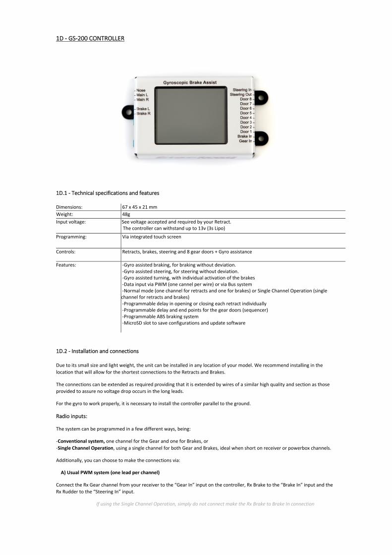
1D - GS-200 CONTROLLER
1D.1 - Technical specifications and features
Dimensions: 67 x 45 x 21 mm
Weight: 48g
Input voltage: See voltage accepted and required by your Retract. The controller can withstand up to 13v (3s Lipo)
Programming: Via integrated touch screen
Controls: Retracts, brakes, steering and 8 gear doors + Gyro assistance
Features: -Gyro assisted braking, for braking without deviation. -Gyro assisted steering, for steering without deviation. -Gyro assisted turning, with individual activation of the brakes -Data input via PWM (one cannel per wire) or via Bus system -Normal mode (one channel for retracts and one for brakes) or Single Channel Operation (single channel for retracts and brakes) -Programmable delay in opening or closing each retract individually -Programmable delay and end points for the gear doors (sequencer) -Programmable ABS braking system -MicroSD slot to save configurations and update software
1D.2 - Installation and connections
Due to its small size and light weight, the unit can be installed in any location of your model. We recommend installing in the
location that will allow for the shortest connections to the Retracts and Brakes.
The connections can be extended as required providing that it is extended by wires of a similar high quality and section as those
provided to assure no voltage drop occurs in the long leads.
For the gyro to work properly, it is necessary to install the controller parallel to the ground.
Radio inputs:
The system can be programmed in a few different ways, being:
-Conventional system, one channel for the Gear and one for Brakes, or
-Single Channel Operation, using a single channel for both Gear and Brakes, ideal when short on receiver or powerbox channels.
Additionally, you can choose to make the connections via:
A) Usual PWM system (one lead per channel)
Connect the Rx Gear channel from your receiver to the “Gear In” input on the controller, Rx Brake to the “Brake In” input and the
Rx Rudder to the “Steering In” input.
If using the Single Channel Operation, simply do not connect make the Rx Brake to Brake In connection

B) Bus system (Sbus/Xbus/Udi/Srxl/Exbus)
Connect the Bus output from your receiver to the “Gear In” input on the controller.
Please note! We recommend to always pass the RxSteering channel through the Controller.
This guarantees that the steering servo remains centred and blocked when the retracts are in
their retracted position and whilst the retracts are in movement; this is especially important if
using the Coupling System for steering. Additionally, this also simplifies the radio setup as it’s
not necessary to create special mixes to prevent the steering servo from moving whilst the
gear is up as everything is done by the Controller.
Connecting the Retracts:
Connect the three Retracts to each of the three outputs on the Controller marked Nose G, Main L & Main R. The polarity of the
connector is indicated on the Controller.
Connecting the Brakes:
Connect the Brakes to the two outputs on the Controller marked "Brakes". The polarity of the connector is not important for the
Brakes. The central pin is not used.
Connecting the Steering Servo: Connect the Steering Servo to the output on the Controller marked "Steer Out”.
Connecting the Gear doors:
Connect the actuators to the outputs “Door” marked from 1 to 8. You can connect more than one actuator to each of these
outputs using a Y lead however any adjustment made will affect everything connected to the Y lead equally.
1D.3 - Power supply
Power should be provided from a Lipo battery with MPX type connector, separate to the rest of the models electrical system. This
battery will provide power to the Retracts and the Brakes. (be especially careful when soldering the connector to assure correct
polarity) Each pole (+ and -) on the MPX uses all three pins from that side of the connector. With a 500mAh size battery you will
have more than enough for a full day flying.
¡Warning!
Check for correct polarity before connecting the battery. Correct polarity is clearly marked
on the Controller with "Battery +" and "Battery - “.
Connection of a battery with reverse polarity will destroy the unit beyond repair.
The voltage to be used depends on which Retract size you will be controlling and
oscillates between a 2s and 3s Lipo. Please confirm the Retract Voltage table found
in section 2 of this manual as the wrong battery choice will result in an irregular
operation as well as damage to the retracts.
Read all warnings found in section 0A - WARNINGS before connecting a battery.
The Controller has an internal automatic switch controlled by the "Gear in" input, which turns the unit off when not in use. As such
there is no need to disconnect the battery from the Controller between flights. It is however advisable to disconnect the battery
once the days flying has been completed, as there is still a small amount of power drain even when not in use which following a
few weeks can result in the battery being completely empty.

Please note! The following applies if you are using voltage regulators, power distribution board or
Retracts running from a 3s Lipo:
Regardless of the battery voltage used to power the Retracts, be it 2s or 3s, the steering servo will
receive the same power as the receiver/powerbox, via the "Gear in" input on the Controller. As
such, if the Controller is connected to the receiver and this is set to 5.9v, this is the voltage that
the steering servo will receive, regardless of the battery that is powering the Retracts.
Due to this, if you are going to use multiple high voltage actuators on the gear doors, make sure
that the input “Gear In” is powered from a supply with sufficient current (ideally we would
recommend pulling power from a powerbox, and not from the receiver directly)
It is also important that the voltages that the Controller receives from "Gear in" and "Brake in"
are the same, as internally they are connected and using different voltages on these two inputs
can cause the unit not to function correctly. If you need to draw these two channels from
different power sources (one from a receiver at 5.9v and one from the powerbox at 7.4v)
simply remove (disconnect)the red wire (positive) from the connector which has the voltage
that you don't want to reach the steering servo.
1D.4 - Programming
Video manual: https://www.youtube.com/watch?v=5nJzwbkBpKY
We recommend performing all the programming with the main Retract battery disconnected. Just connect the three
patch leads between receiver and Controller.
Before starting, make sure that none of the channels that are to be used for the Gear, Brakes and Steering are limited,
and all have +100% to -100% throw otherwise the programming may be unsuccessful.
First step is to decide if you will be using one channel (Single Channel Operation) or two channels to control the retracts
and brakes, and then start programming acordingly.
Description of Single Channel Operation:
The input “Gear in” controls the retracts and also the brakes. How this works is similar to that of a turbine, in which the trim
controls whether the turbine is on or off and the stick regulates the power. For example, from -100% to -75% controls retracting
and extending the gear, while -75% to +100% controls the power applied to the brakes.
Main screen:
All programming is done via the integrated touch screen. The different programming options are split between different
screens, allowing the setup to be quick and easy.
Upon powering the controller, it will briefly show the home screen and will then enter into the main page which shows
the current status (Main)
The Main screen shows the following information:
-Line 1: Battery voltage for the retracts
-Line 2: Status (Gear Up / Gear Down)
-Line 3: Status of the gear doors, 1 – 8 (green=open, red=closed)
-Bars: If the retracts are extended, it shows the power consumption of the brakes. During any other status, it shows the
power consumption of each of the three retracts.

Programming
Programming the controller can be done with or without its own auxhilary battery connected.
(using just the power received from the receiver or Powerbox)
We recommend not connecting its auxhilary battery, or the actuators, until the first steps are
completed in order to prevent unwanted unexpected movements.
To enter into the rest of the menus, you need to exit the Main page by pressing the red X in the top corner of the screen
and then selecting “Setup” on the home screen.
This will show you all the menus available, split between two screens.
Radio:
Before starting to setup this screen, decide how you are going to connect your receiver to your controller, be it by
multiple wires or a single wire Bus system. The Bus system is convenient if using a radio with many channels (example:
16ch) but are using a “small” receiver (example: 8ch)
For this example, you could setup the radio to use channels 9, 10 & 11 for retracts, brakes and steering, while leaving
channels 1 to 8 for the remaining functions.
Once decided, first go into:
RCMode (to select the input method)
In the top segment of the screen, you will see how the input signal will be received. Keep pressing “Change”
until your desired method is shown. The options available are:
-Standard Servo Input (usual system of one wire per channel)
-Futaba SBUS
-UDI, MPX, JR ModeB, SRXL
-JR XBUS ModeA
-Jeti EX Bus
If using any of the Bus systems, you need to tell the controller which of all the Bus channels are to be used for
what functions. This is done with the + / - buttons shown next to each of the three functions shown
For the above example, we would set Gear as ch9, Brake as ch10 and Steering as ch11

RCSet (Setting the gear and brake end points)
Follow the steps shown on the screen of Gear Up, Gear Down, No Brake and Maximum Brake, setting the
radio switches in the correct position of each step and pressing next to move from one to another. Check the
signal being received (in pulses) changes accordingly to assure that the channel assignment is correct.
If during this step no input signal is received for the “Brake In”, the system will adopt Single Channel
Operation mode.
Power-Up:
You can choose which of the three initialization modes is used when turning the system on. Each time you press
“Change” it will cycle through the three different modes. You can choose between:
Inmediate: The gear, brakes and doors activate inmediately, as per the position of the gear swith on the radio, regardless
of if this is in gear retracted or extended position
Check switch: The system will only activate once the gear switch is placed in the gear extended position, preventing as
such that the retracts are activated accidentally upon turning the model on if the switch is not correctly set.
Cycle Switch: The system will only activate once the gear switch performs a full cycle (gear extended, gear retracted,
gear extended)
Servos (gear doors travel):
The end points for each of the 8 gear doors is set from this menu.
Select which gear door you wish to program (1-8) using the + / - buttons at the top of the screen (Servo Output Nr.)
Press on the OPEN button, and adjust the position (end point) for that gear door fully open by using the “Position” + / -
buttons

Now do the same having pressed the CLOSE button, setting this time the end point for the fully closed position. Then
repeat as many times as necessary for as many gear doors as you have.
If this setup results in values under 60% of the travel, consider reviewing the mechanical links (servo arm, control horn, etc) in
order to be able to use a higher percentage and as such gain the maximum torque available from your servo.
Assure that the end points set are correct and do not leave the servo under load, which can result in the servo burning
out rapidly. One recommendation is the use of a polimiter to assure that there are no excessive power drains.
SV Speed (gear door speed):
In this section you can adjust the speed at which we want the gear doors to open, and close, each programmable
independently.
The process is the same as those on the previous screen for Servos, selecting the desired gear door output and then
selecting the time it takes to move from Open to Close or vice-versa.
Sequencer:
The sequencer allows up to 10 steps, each entirely programable independently, as follows:
-Step 0, called Gear Up (gear retracted, flying mode)
-Steps 1 to 8
-Step 9, called Gear down (gear extended, landing mode)
The sequence steps are the same for retracting or extending. Program one way and the controller will automatically
reverse for the other way.
On each of the 10 steps, simply set up the final position of each of the 11 outputs for that step (3 retracts and 8 doors)
Example. A first step could be to open the gear doors, a second step would be extending the retracts and then a third
step could be close the gear doors. Having up to 10 steps available allows you to add any level of complexity desired,
such as opening of gear doors individually, then one retract, then another, however you desire.
To move on to the next step, use the Step + and – buttons

In each step we will use the + and – buttons to set the time at which we want this step to start (in fractions of 0.1 of a
second). This time counts from the previous step.
To change the resulting position of a retract at the end of the current step, simply press on each one of the retract
buttons accordingly, these will go red if they are to end up retracted, or green if they are to end up extended.
To change the resulting position of a gear door at the end of the current step, we need to access them via the Doors
button, and in the same was as for the retracts, press each outputs button so that they are Red (closed) or Green
(open) as desired for the end of that step.
Note:
-From the sequencer, you set the start time for each step, however the duration of that step will depend on the time set
for that actuator in the SV Speed screen seen previously. As such, it is important that sufficient time is allowed for the
previous step to complete its full movement before the next step starts (unless the desired result is of overlapping
movements, and these can do so freely without obstructing each other’s paths)
-The last step (step 10) will not execute until all retracts are fully extended or retracted, regardless of the times and
speeds which we have set in the controller. This is done to assure that the closure of gear doors is never done while the
gear is still out and retracting, thus avoiding any possible damage to gear doors.
If you do not need to use all 10 steps, simply use as many as required, and then your duplicate your last step to all
remaining steps that follow it.
Steering:
From this screen we can adjust everything to do with the steering, be it the center, the rotation direction, the gyro, etc…
Thanks to this, if you want to use the same signal as the rudder (via a Y lead) you can, saving a radio channel while
maintaining full setup possibilities.
The first screen allows us to set up the servo subtrim (center), the travel of the servo (gain) and the gyro gain. In order to reverse
the servo or gyro, simply use negative numbers instead of positive numbers.
Brakes:
From the Brake adjust screen, we can choose between:
Proportional or Heading Hold: Proportional allows the gyro to correct using one brake or the other at the time when a
momentary external influence would normally cause the model to deviate from its path, while Heading Hold allows the
gyro to remain active for longer so that if the model has a prolonged tendency to deviate it can correct in a more
continuous manner,
We have four parameters that we can set up:
Limit: Allows you to limit, if desired, the maximum brake inputs (if the brakes brake too much, as may happen with light
models). It also allows you to adjust each one of the brakes independently.
Pulse ratio: Allows braking with ABS, in which the brakes turn on an off rapidly under braking to prevent causing flats on
the tires. You can choose between five types of ABS braking.
If used, Brake Pulse Ratio does not fully de-activate the brakes in ABS mode, it simply reduces the power applied to the brakes
during these pulsations. The 5 ratios available indicate what power is applied during this lower of the two pulsations.

Example, a ratio of 1/3 implicates that during braking, the ABS will provide 100% of your power input to the bakes during the
high peaks and 1/3 (33%) of that power during the low peaks. If you do not want to use ABS and as such have full maximum
braking, select 1/1
Steering Mix: This mixes the steering channel to the brakes, allowing to turn the model aided by the brakes as well as
the steering (often used in warbirds such as the P47)
Gyro Mix: In the same way that the Steering Mix allows the gyro to control the steering, this option allows the gyro to
control the brakes in order to help maintain a straight trajectory under braking.
Note:
When adjusting these values, always do so progressively, too higher value can result in the brakes being permanently
active, which can cause vibrations in the model due to it being forced along with the brakes on.
Screen Calibration:
If the touch screen buttons are not working correctly, perform the following to recalibrate the screen.
Press the screen and then turn the controller on, this will make it enter calibration mode. Now simply follow the instructions
shown on screen.

1D.5 - Wiring diagram:

1E - E-BRAKE
1E.1 - Technical specifications and features
Weight: 12g
Input voltage: 9v (maximum 1.5A per wheel) 7,2V (2S Lipo, 5-NiCd NiMh); Life de 2s y 3s (A123)
Controls: Proportional brakes with optional ABS
1E.2 - Installation and connections
Due to its small size and light weight, the unit can be installed in any location of your model. We recommend installing in the
location that will allow for the shortest connections to the Retracts and Brakes.
Connecting the Radio (radio inputs):
Connect the servo connector to your receiver or powerbox, to the channel that you will use to control the brakes.
Connecting the Brakes:
Connect the Brakes to the outputs on the Controller. The polarity of the connector is not important for the Brakes.
1E.3 - Power supply
Power should be provided from a battery separate to the rest of the models electrical system. This battery will provide power to
the Brakes.
The Controller has an internal automatic switch controlled by the radio input, which turns the unit off when not in use. As such
there is no need to disconnect the battery from the Controller between flights. It is however advisable to disconnect the battery
once the days flying has been completed, as there is still a small amount of power drain even when not in use which following a
number of weeks can result in the battery being completely empty.
¡Warning!
Check for correct polarity before connecting the battery.
Connection of a battery with reverse polarity will destroy the unit beyond repair.
The voltage to be used is a direct 2s Lipo.

1E.4 - Programming
Before starting, setup the required channel on your radio with the desired control input and make sure that the channel
is not limited and has +100% to -100% throw, otherwise the programming may be unsuccessful.
Hold down the button/led on the controller and turn on the receiver.
Once the receiver is on, wait 1-2 seconds and release the button/led. The button/led will then remain flashing with
single flashes. This indicates that we have entered the programming mode.
The first step is to program the minimum brake position. Simply place the TxBrake switch in the minimum brake on
position (where it should start to brake) and press the button/led. The led will now start a sequence of 2 flashes.
Now we set the TxBrake to its maximum brake position and press the button/led. The led will now start a sequence of 3
flashes.
In this last step, we can program the ABS of the brakes. These run in a loop with 5 options (1 of continuous braking, and
4 different ABS pulse rates, showed by the flickering led). Press the button as many times as required until finding the
frequency of ABS that you wish to use. As they all run in a loop, don’t be afraid to go through them all to find the one
you like the most, and then keep going round until finding it again. The different frequencies are also identifiable
through the LED.
If sharing the elevator stick for Brakes, it is recommendable to use only the final third of the stick travel to work the brakes.
This will assure that the brakes are not activated in its neutral position, thus saving battery power.

2 – MECANISMS
2A - RETRACTS
Each retract system is made up of a sophisticated main cage, milled out of a single aeronautical grade 7075-T6 aluminium block
which houses the rest of the components.
The strong cage along with the square thread spindle make up an immensely strong unit providing utmost reliability. The perfected
design can be dismantled with just 4 bolts, making maintenance or any change of parts extremely simple.
All systems made by Electron Retracts are designed to be controlled via current limitation, avoiding as such the need for encoders
or limit switches which could otherwise be susceptible to causing problems due to working in a difficult and dirty environment,
receiving heavy impacts and vibrations.
This also acts as a safety feature, due to the fact that if the strut encounters an obstacle which generates a higher current
consumption, the Controller will detect this and will cut power to that retract, being able to then restart the cycle from that point.
There are a number of different sized retracts available to choose from. Choice should be made based on the final overall weight of
the model and are then matched with our large selection of struts and trunions to find the perfect combination for your model.
2A.1 - Technical specifications and features
All our systems are in constant evolution, so for the most up to date information, please visit our website: www.electron-
retracts.com
Retract Weight Max model weight
Cicle time at 8v
Pin diameter Voltage allowed
Torque (Kgxcm)
ER-30 75 g 8 kg 2 sec. 4-8mm 3s Lipo (12,6V) 14
ER-40 140 g 17 kg 2 sec. 6-13mm
2s Lipo (8,4V) 35
ER-50 (Normal Torque)
290 g 30 kg 3 sec. 8-16mm 2s Lipo (8,4V) 55 (GS-200/GS-200Pro)
ER-50 (High Torque)
290 g 30 kg 7 sec. 8-16mm 2s Lipo (8,4V) 150 (GS-200/GS-200Pro)
ER-50 NG 290 g 30 kg 3,5 sec. 8-16mm 3s Lipo (12,6V) 200 (GS-200Pro)
The difference between the ER-50 and the ER-50 HT is the torque of the retract, with the HT being ideal for use in models with
extremely long and heavy struts or which are connected to gear doors which act a large aerodynamic brake.
2A.2 - Installation and connections
If during the installation of the retracts you need to operate them, always do so via a Controller or use our Manual Controller.
Always assure to screw the retracts to the model onto a flat surface.
The retracts come with four screw holes through which the unit will be secured. Wood screws can be used, however for the most
secure fitting the use of bolts and blind nuts is recommended.
The size of these bolts are M3 for the ER-30, M4 for the ER-40 and M5 for the ER-50.
It is vital that the surface onto which the retract is mounted is flat. Otherwise, when tightening the screws, the structure can suffer
small deformations which can affect the correct workings of the unit.
Be careful to make sure that the retract can open and close fully without any kind of obstacles or hitches at any point in
its path.
¡Warning!
Take special care to assure that the retract can reach full travel and is not stopped short.
Full mechanical block is only obtained once full travel is reached.

Often, in the last part of retraction, the wheel makes contact with the inside skin of the wing, which can cause the retract to stick
and not extend due to the slider having become jammed without reaching the end of its full travel. In this case, a solution must be
found to allow full travel to be made without the wheel touching anything at any time. A simple solution is to supplement the
mounting bracket by a few milimiters, in effect lifting the whole unit further away from the top of the wing.
If once installed you realize that the retraction angle is not correct for your model, never attempt to mechanically jam the end
points in order to modify the angles. This would be preventing the retract from mechanically locking and the entire system will be
damaged during landing. Instead, please contact your local distributor to find an appropriate solution (swapping the trunnion for
one with the appropriate retraction angle)
Each retract is provided with a lead, these connections can be shortened or extended as required providing that it is extended by
wires of a similar high quality and section as those provided and they are no longer than is truly necessary in order to assure no
voltage drop occurs in the long leads.
Even though all Electron retracts have the same wiring, the connections do vary depending on which Controller is being used. You
can find the details and wiring diagrams for each controller within this manual as follows:
RB-45: Section 1B
RS-200: Section 1C
GS-200: Section 1D
Once all the necessary connections are made, double check the entire system before turning on the first time. It is very easy to
make a mistake when soldering or crimping any one of the wires or connectors, especially if multiple connections are required.
One mistake can result in a short-circuit which will destroy the controller beyond repair.
It is not possible to share the negative lead of the retract with that of the brakes. All leads of the retract need to be completely
independent to those of the brakes.
You can reverse the polarity on the retracts and no damage will be done, the only result is that the motor will operate in reverse.
Please note that the brakes and steering are only activated when the retracts are in the controllers gear down position. As such,
reversal of the retract should only be required if the trunnion is also reversed.
2A.3 - Power supply
Despite all our controllers being able to work with up to 13v (3s Lipo) caution must be taken as the power source to be used is
based on the retracts which are to be connected to it.
2A.4 - Use and warnings
Use the Controller, never connect a battery directly to the Retracts
The Retracts must only ever be operated via the Electron Retracts Controllers. NEVER use the Retracts without a Controller or with
other brands of Controllers.
Our Controllers detect the end point of the Retract via the power consumption. Using a direct battery or other another brands
controller will not only provide inadequate current, but will also likely not cut off at the right time, resulting in damage to the
whole system.
If you wish to move the Retract without connecting it to the model, use our Manual Controller.
Allow sufficient time to fully extend before landing
Before landing, assure sufficient time is allowed for full deployment of the gear. Bare in mind that electric retracts take several
seconds to deploy, and as such this time must be taken into account before touchdown. Full mechanical lock is only gained after
the full cycle has been completed, otherwise if not in the fully locked position it will be the spindle that receives the impact of
landing instead of the cage.
The end points are detected by the increase in power consumption and all retracts have shock absorbers designed into them in
order to protect the gear boxes. It is for this reason that following the end of each cycle you can hear a second short spool up of
the retract. This is the controller unloading the shock absorbers in order to prevent unnecessary early ware.
Connect all retracts and beware of possible delays if not using all three retracts.
The controller needs to detect that all three retracts have reached their end points in order to then activate the brakes and
steering. If during the cycle the controller does not detect that all three retracts have reached their end points, it will activate the
brakes and steering following a delay of 5-10 seconds following when the cycle would normally finish. This can cause confusión
when setting up retracts if nota ll three are connected and as such a delay is observed.

2A.5 – Maintenance and breakdown
As with any mechanical system, it is recommendable to perform basic maintenance to assure a long life of the system.
Electron Retracts has designed a compact system where the most delicate components are protected by the main structure made
from aeronautical 7075-T6 grade aluminium, all of which keeps maintenance to a minimum.
Despite this, it is still recommendable to:
Keep the spindle clean and lubricated: especially if flying from non-tarmac runways. Electron Retracts has a specific special grease
for spindles which is easy to apply. After cleaning the spindle and slider, apply one drop of grease on each end of the slider and
perform several cycle’s so that the grease is well distributed along the spindle.
Keep the trunion clean: the tolerance between the trunion and the cage is very precise, so any accumulation of dirt can cause the
system to stick or not function adequately.
RETRACT, EXPLODED VIEW
Following cleaning or replacing components, always remember to reapply Electron Retracts grease to the spindle.

2A.6 – Interchangeable Trunion
The design of our mechanisms allows for the use of different trunions. In changing the trunion, it is possible to change the angle of
retraction, or to modify a main gear to a nose gear just by installing one of the steering systems available. It is also possible to use
our retracts in standard mode or reverse, just by reversing the trunion.
If necessary, contact with your local distributor regarding different trunions available and which suits your needs best.
2B – STEERING MECANISMS
At Electron Retracts, in addition to the conventional steering system, we offer a total of four systems for you to choose between,
depending on your own models requirements. These are:
Simple Pull-Pull:
This is the classic system where the servo is mounted permanently in the model and the steering is made via pull pull wires.
Coupling System:
This is a system designed by Electron Retracts, in which the servo is connected via either a rigid push rod or pull pull wires to the
retract. When retracting, the nose leg detaches itself from the steering system and then reattaches when extended.
Thanks to a new and innovative system, we have been able to do away with the centering spring which kept the wheel locked
when retracted. Simplifying the system in this way guarantees a perfectly centered retraction and deployment of the nose leg.

Servo Plate:
Is a system where the servo is screwed onto a base plate which moves with the retract in a way that the servo is always connected
to the strut via a rigid pushrod. This is probably the best of all the systems, but requires more space in the fuselage to account for
the movement of the servo along with the retract.
Inverted Steering:
Works the same as the Servo Plate, but is for when the retract is installed inverted.

3 - STRUTS
3.1 - Technical specifications and features
All of the Struts made by Electron Retracts are made from aeronautical 7075-T6 grade aluminium, milled using a 5 axis CNC to the
sizes required for each model.
Many sizes and lengths are available, with different weights for each depending on the size.
3.2 - Installation and connections
Installation is simple, just slide the strut into place, adjust the angle and tighten the grub screws to secure it in place
Offset
Electron Retracts struts offer the ability to change the offset of the wheel as required. Thus, guaranteeing that the fit of the wheel
in the wing opening is correct, regardless of the model. This makes these struts the most versatile on the market.
To adjust the offset, simply locate the grub screw on the rear of the Strut and tighten or loosen as required until obtaining the
desired angle. Prior to making the adjustment to this grub screw, extract it fully and apply a drop of the provided Loctite to prevent
it from being able to come loose due to vibration, resulting in the loss of the desired angle.
Adjusting the offset
Electron has developed a main strut with adjustable offset. It allows you to adjust the offset precisely for a perfect fit in your model (wing opening). This feature offers the leg great versatility regardless of the model. Procedure to adjust the offset: Adjusting the angle is very easy. It is adjusted by one special M4 grub screw (with a stainless steel ball on the tip) that you can find in the back of the leg, as the photo below shows. Simply turn with an allen key and adjust to the desired angle.
To prevent the screw from moving with use, it is important apply a small amount of threadlock to the screw before securing in place. We include for this a small tube of threadlock with the struts.
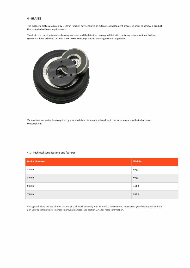
4 - BRAKES
The magnetic brakes produced by Electron Retracts have endured an extensive development process in order to achieve a product
that complied with our requirements.
Thanks to the use of automotive braking materials and the latest technology in fabrication, a strong yet proportional braking
system has been achieved. All with a low power consumption and avoiding residual magnetism.
Various sizes are available as required by your model and its wheels, all working in the same way and with similar power
consumptions.
4.1 - Technical specifications and features
Brake diameter Weight
32 mm 40 g
39 mm 60 g
50 mm 111 g
75 mm 352 g
Voltage: All allow the use of 6 to 13v and as such work perfectly with 2s and 3s, however you must select your battery voltaje base
don your specific retracts in order to prevent damage. See section 2.A1 for more information.

4.2 - Installation and connections:
The brake disk is placed inside the wheel hub, locking in place through three holes which slot into three screw heads which stick
out from the hub. The electromagnet is guided and positioned by the actual wheel axel over an aluminum sleeve which must be in
contact with the interior bearing of the wheel/hub.
¡Warning!
Due to the electromagnet needing to be correctly and precisely installed, we can only guarantee a successful
operation when used with Electron struts.
The brakes are connected to the appropriate outputs on the Electron Retracts controller. Of the three pins on the connector, only
the outer two provide power. See diagrams.
If desired, it is possible to connect two brakes using a "Y" lead connected to the "Brakes" output on the controller
Note that the system increases its braking power with use as the brake pads becomes more and more worn.
The time comes (once the brake pads are fully worn out) that the brake disk comes into contact with the electromagnet directly, in
which case, metal against metal friction occurs. When this happens, return to factory in order to recycle the system (contact your
local distributor)
To see how to program the brakes, check out the specific instructions for your controller.

5 – LINEAR ACTUATOR
The Linear Actuator by Electron Retracts was designed to provide a solution to gear doors without needing to use air pistons,
offering an entirely electric gear system.
All parts are produced from aeronautic aluminum 7075-T6 in CNC milling machines with very precise tolerances before being
anodized prior to final assembly when they receive their motor, gearbox, and electronics. The result is a very compact, robust and
slop free system. The innovative three-point adjustable mounting bracket and small size mean that the unit can be installed
practically anywhere, even in tight spaces.
Note that the Linear Actuator by Electron Retracts has been designed to be used on gear doors. It is not recommended to be used
on flying surfaces such as flaps or slats.
5.1 - Technical specifications and features
Available in three sizes:
Stroke: 20mm, 25mm or 30mm. (tolerance +- 1mm)
It is not possible to set mid points, only open, closed or shutoff due to overload are available.
Versions: High Torque: 60N at 6v, in 3,5s (50N at 5,5v in 4,5s)
High Speed: 45N at 6v, in 2,5s (35N at 5,5v in 3,5s)
Commun to all:
Weight: 35g
Voltage: 4,5 to 6v
Maximum drain: 1,1A
Cycle time: 2,5 to 4,5 seconds depending on voltage and door weight
Connector: Same as servo.
Includes: Actuator, three position mounting bracket and preinstalled ball link.

5.2 – Installation and connections
The Linear Actuator comes with a variable 3 point mounting bracket. According to the geometry of our gear door, we will use one
mounting point or another.
Maximum pivot with the provided mounting bracket
Once we are clear on the geometry, we screw the actuator into the model using its own support, attaching the door to the ball link.
To facilitate the installation in any model, the actuator includes an electronic chip which allows it to be controlled as if it was a
servo, in other words, connected directly to a receiver, powerbox or one of our controllers with sequencer outputs (this would be
the Electron Retracts RS-200 and GS-200).
It is important to note however that despite being connected in the same way as a servo, the Linear Actuator is not proportional, it
can only be stopped due to current overload. For this reason, its installation must be able to allow the actuator to open and close
fully. This is why three lengths of Linear Actuators are available, to assure that the correct and full travel can be chosen for each
application.
5.3 – Power supply
Being connected in the same way as a servo, additional power is not required as it will receive all power required directly from the
receiver, powerbox or controller to which it is connected.
Remember: If connecting the Linear Actuator to one of the Electron Retracts controllers, the design of the controllers provides
power to the sequencer outputs at the same voltage as the power received by the actual controller to its "Gear Input". As such, if
the receiver or powerbox regulates its power output to 5v, this will be the voltage received by the Actuator, and not the 7.4v or
11.1v provided by the retract battery.
5.4 - Programming
Programming is just like an all or nothing servo, as this is exactly how the Actuator works. We just need to provide it with a
negative signal (-100%) so it starts to travel in one direction, and a positive signal (+100%) so it travels in the opposite direction.
(see programming of RS200 in point 1C and GS200 in point 1D of this manual)
Assure that the Actuator has full throw in both directions with a clear path.

6 - YOUTUBE
In addition to this manual, we recommend visiting and subscribing to our YouTube channel:
https://www.youtube.com/user/ElectronRetracts
Here you will find Video Manuals of all our products, as well as tutorials, recommendations, further explanations and much more.

7 - TERMS & CONDITIONS
Electron Retracts is a registered trademark (CM 013441449) property of Turbinas y Compresores Jetsxoel SL.
In compliance with the Ley Orgánica 15/1999 of 13th of December about Personal Data Protection and the Ley 34/2002 of 11th of
July of services, information and e-commerce we hereby advise that your personal details will be treated and incorporated into a
data base property of Turbinas y Compresores Jetsxoel SL with intention to improve customer care, offer and present services
associated with our products in general and especially those in which you have shown interest.
In accordance with the above, you hereby grant express authorization for your data to be trated by Turbinas y Compresores
Jetsxoel SL to comply with the afformentioned and to send you further information regarding products and services.
We also advise that you can oppose your data being treated by writing to the postal address: Turbinas y Compresores Jetsxoel SL,
Poligono Industrial PPI-7, Parcela K, Nave B9, Lg Budiño 36475 Porriño (Pontevedra) Spain along with a copy of your identification.
Turbinas y Compresores Jetsxoel SL will accept no returns without prior agreement.
Turbinas y Compresores Jetsxoel SL, social address at Poligono Industrial PPI-7, Parcela K, Nave B9, Lg Budiño 36475 Porriño
(Pontevedra) Spain, registered in the Registro Mercantil de Pontevedra, al Tomo 3279, Libro 3279, Folio 217, Hoja PO-41899,
primera inscripción. Contact detail: [email protected]
This instruction manual is provided along with the purchase of a product by Electron Retracts and its sole purpose is to facilitate
the correct use and installation in an rc model to be used for hobby.
Electron Retracts can not supervise the correct installation and use given to its components by each client and as such can accept
no liability for personal or material damages of any kind due to misuse.
All attempts have been made to make this manual as complete and up to date as possible, however due to the ongoing
development of the described products, some products may differ from their description above. If you consider that the product
received is significantly different to its description, or have queries regarding these differences, please contact your local
distributor who sold you the product, or if unsuccessful directly with Electron Retracts.
The warranty offered by Electron Retracts covers all components against mechanical failure due to the production process or
materials used during the first 2 years since purchase. The company reserves the right to charge for any repair caused by client
misuse, which includes but is not limited to; connecting a battery with reverse polarity, connecting a battery direct to a retract
without going via a controller, joining multiple wires through a single connector pin, landing without having the retract in its fully
extended position and its use in professional applications or any other misuse not described in this manual.
Electron-Retracts reserves the right to modify this manual without prior notice.
For more information, please visit the official Electron Retracts website: www.Electron-Retracts.com
Manual v1.0 – October 2020 – English ©Electron-Retracts