electromagnetic, elastic and electro-elastic waves - philips bound... · philips tech. rev. 33,no....
TRANSCRIPT
Philips tech. Rev. 33, No. 11/12 311
Electromagnetic, elastic and electro-elastic waves
C. A. A. J. Greebe
Introduetion
Electronics is very much concerned with electro-magnetic waves - their generation, modulation, pro-pagation, reception and processing. Electromagneticwaves may be transmitted through space or they maybe guided by wires or other types of transmission line.Sometimes, especially in the microwave region,electromagnetic waves appear in the generating orprocessing equipment itself. Two important examplesare the resonant cavity - where energy can be storedin the form of standing waves - and the delay line -where information can be stored in the form of modu-lated travelling waves.
Electronics also makes use of elastic waves: thequartz-crystal resonator is a very early and well knownexample. The use of elastic waves offers in many casestwo notable advantages : the velocity of propagationis some 105 X smaller than that of electromagneticwaves - so that, in 1 cm of a solid, elastic waves aredelayed by the same amount as electromagnetic wavesin 1 km of a cable; also, in certain carefully preparedmaterials, the attenuation of elastic waves can berelatively very small.
Elastic waves in solids are almost always generatedand detected electrically. The conversion of electricsignals into mechanical signals and vice versa is usuallydone by means of piezoelectric materials such asquartz; sometimes magnetostrictive materials are used.
Attempts to generate high-frequency elastic waveswere for a long time limited to frequencies below100 MHz because the electromechanical conversionwas always done with mechanically resonant trans-ducers. Such transducers must be only one or a fewhalf wavelengths in thickness and above 100 MHz theybecame so thin as to be difficult to make or too fragilefor practical use. This difficulty was surmounted duringthe fifties [ll and progress was such that some yearslater (1966) it was possible to generate and detectcoherent waves of no less than 114 GHz [2l. One ofthe features of this breakthrough was the integrationof transducer and medium: for example, elastic wavesin a quartz crystal were generated and detected byvirtue of the piezoelectric property of the crystal it-self [2l.
Dr C. A. A. J. Greebe is with Philips Research Laboratories,Eindhoven, and Professor Extraordinary at Eindhoven UniversityoJ Technology, Prof. Greebe is now Director of the Institute forPerception Research (IPa), Eindhoven.
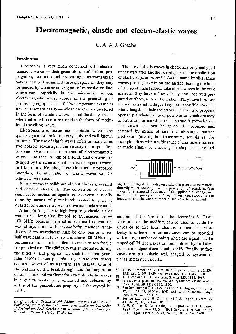
The use of elastic waves in electronics only really gotunder way after another development: the applicationof elastic surface waves rsi, As the name implies, thesewaves propagate only on the surface, leaving the bulkof the solid undisturbed. Like elastic waves in the bulkmaterial they have a low velocity and, for well pre-pared surfaces, a low attenuation. They have howevera great extra advantage: they are accessible over thewhole length of their trajectory. This unique propertyopens up a whole range of possibilities which are easyto put into practice when the substrate is piezoelectric.The waves can then be generated, processed anddetected by means of simple comb-shaped surfaceelectrodes (interdigital transducers, see fig. 1); forexample, filters with a wide range of characteristics canbe made simply by choosing the shape, spacing and
Fig.!. Interdigital electrodes on a slice of a piezoelectric material(interdigital transducer) for the generation of elastic surfacewaves. The temporal frequency of the applied a.c. voltage, andthe spatial frequency of the 'fingers' must correspond to thefrequency and the wave number of the wave to be excited.
number of the 'teeth' of the electrodes [4l. Layerstructures on the medium can be used to guide thewaves or to give local changes in their dispersion.Delay lines based on surface waves can be providedwith a large number of points where the signal may betapped off [5l. The waves can be amplified by drift elec-trons in an adjacent semiconductor rei, Finally, surfacewaves are particularly well adapted to systems ofplanar integrated circuits.
[1) H. E. Bömmel and K. Dransfeld, Phys, Rev. Letters 1, 234,1958 and 2, 298, 1959, and Phys. Rev. 117, 1245, 1960.
[2) J. I1ukor and E. H. Jacobsen, Science 153, I I I 3, 1966.[3) A survey is given in: R. M. White, Surface elastic waves,
Proc. IEEE 58, 1238-1276, 1970.[4) See for example J. H. Collins and P. J. Hagon, Electronics
42, No. 23, 97, 10 Nov. 1969, and R. F. MitcheIl, Philipstech. Rev. 32,179, 1971.
[5] See for example J. H. Collins and P. J. Hagon, Electronics43, No. 2, 110, 19 Jan. 1970.
[6) J. H. Collins, K. M. Lakin, C. F. Quate and H. J. Shaw,Appl. Phys. Letters 13,314,1968. See also J. H. Collins andP. J. Hagon, Electronics 42, No. 25, 102, 8 Dec. 1969.

312 C. A. A. J. GREEBE Philips tech. Rev. 33, No. 11/12
In recent years there has therefore been a growinginterest in all sorts of wave phenomena - bulk wavesand surface waves, electromagnetic waves and elasticwaves and combinations of these in piezoelectricmaterials. It seemed to be useful to attempt a systematicreview of these various forms against a background ofconventional, well known forms of wave propagation.,This article, therefore, is meant as a sort of 'introduc-tion to waves, and is of a tutorial nature; it gives noscientific 'news' but presents known material andpoints out relationships. The opportunity will also betaken of discussing certain perhaps in practice lessimportant but nevertheless remarkable wave phenom-ena such as helicon waves.In the first part of the article we shall consider wave
propagation in unbounded media - for example in freespace, in optically anisotropic media and in conductorswith and without a magnetic field - starting from thedifferential equations for the appropriate variables ofthe medium. The travelling waves that we find arecharacterized by an angular frequency w (2n X thefrequency) and a wave vector k (whose componentskz, ky and kz are respectively 2n divided by thewavelengths in the X-, y- and z-directions). The wavesmay grow or diminish in both space and time (seefig. 3, p .... ), which is indicated by k or w having animaginary part. A very important aspect of a wavephenomenon is the dispersion relation which is therelation between wand k. Among the subjects dealtwith in this first part of the article are the familiarwaves of light and sound; the strongly attenuatedpropagation in metals resulting in the skin effect; avariant of this in a strong magnetic field, the 'helicon'waves, and some longitudinal electric waves. We shallalso consider a situation where the wave does not pro-pagate in the direction ofthe wavevector k, a matter tobe borne in mind when considering anisotropic mate-rials, such as crystals, whether carrying bulk or surfacewaves.The second part of the article deals with the coup-
ling of waves in unbounded media. Wave propagationin piezoelectric materials can be very complicatedbecause the electric and elastic variables are not inde-pendent of each other. If, however, the coupling isweak, the problem can be considerably simplified byregarding the waves as coupled electric and elasticwaves, each of which would propagate independentlyif the coupling were in fact zero. This method of attackcan also be useful in other cases where there are manycoupled variables. Among the examples discussed hereis the amplification of acoustic waves ('acoustic ampli-fier').
In the third part of the article combinations of wavesthat can exist in two adjacent media are discussed.
These include combinations of incident, refracted andreflected waves and also - our particular concernhere - surface waves. A surface wave occurs in thewell known phenomenon of total internal reflection,but in this case it occurs only in combination with theincident wave and the reflected wave. Modern devel-opments in electronics, however, are concerned withtrue surface waves that are independent of any bulkwaves. A simple example - the Bleustein-Gulyaevwave - will be discussed at length.
In concluding this introduetion attention should bedirected to a problem that will not be dealt with in thisarticle but is of the greatest importance to inves-tigations of wave behaviour in unusual, novel media.In general a travelling wave transports energy ofwhich,usually, a fraction is dissipated in the medium. For agiven real frequency the wave amplitude then dimin-ishes in the direction of propagation (k is partlyimaginary); the medium is passive. There are, how-ever, media which can be activated in one way oranother; in such media waves are possible that becomelarger in the direction of propagation. In the acousticamplifier, for example, the medium is a piezoelectricsemiconductor which is fed with energy by means ofa d.c. current; this energy is partly taken up by theacoustic wave. In a well designed device, the inputsignal re-appears, after traversing the medium, ampli-fied at the output. It is, however, not at all certain thata medium in which such 'amplifying' waves aretheoretically possible will necessarily be potentiallyuseful as an amplifier. It is possible, for example, thatthe medium will exhibit 'absolute instabilities' andreacts to an input signal with an explosive increase ofthe variables. In this case the output signal is no longerrelated in any way to the input signal. A. Bers andR. J. Briggs have given a theoretical approach to theproblem ofhow to decide, on the basis ofthe dispersionrelation, whether a new medium will have absoluteinstabilities or whether it can be used for amplifica-tion [71. The investigation of how the medium reacts toan excitation (input signal, source) is inherent to thisanalysis. We shallleave this question completely asideand consider only freely propagating waves, withoutenquiring how they are generated.
[7] See R. J. Briggs, Electron-stream interaction with plasmas,M.LT. Press, Cambridge (Mass.) 1964, chapter 2.

Philips tech. Rev. 33, No. 11/12 WAVES 313
Waves in unbounded homogeneous media
Main features of the analysis
The method of analysis of wave phenomena inunbounded media will be illustrated by means of asimple one-dimensional example: an infinitely longuniform transmission line with a capacitance ofC(F/m) per unit length and an inductance of L(H/m)per unit length; see fig. 2. Changes in current in thistransmission line give rise to voltage differences acrossthe inductances. The capacitances are charged by thedifference in the currents before and after them, sothat the voltages across the capacitances also change.
L1/
T T T-z
Fig.2. Transmission line with a shunt capacitance Càl and aseries inductance LM per section M. When M ~ 0, with C andL remaining constant, we get a uniform continuous line as dis-cussed in the text.
These qualitative relations between the two wavevariables of this problem, the voltage Vand the currentI can be quantified in two homogeneous linear dif-ferential equations in the spatial coordinate z and thetime t:
OV st-+L-=O,öz èt
oVC-+otOl-=0.oz
The solutions of these equations are exponential func-tions of zand t:
V = Vo exp j(wt - kz),
I = 10 exp j(wt - kz).
All the waves discussed in this article can be describedas functions of this form. The real parts of such com-plex expressions represent the actual physical quanti-ties. If wand k are real, as we shall provisionally as-sume, we have waves in their simplest form: sinusoidalfunctions of position which propagate at the velocitywik, the phase velocity. The amplitudes Vo and 10 canbe complex; the modulus of the complex amplitudeis what we normally call the amplitude whilst its
. argument gives the phase of the disturbance.
Substituting (2) in (I) yields two homogeneouslinear equations for the complex amplitudes:
kVo - wLIo = 0,(3)
wCVo - klo = 0.
There are solutions to (1) only when the determinantof the coefficients of (3) is zero and this condition givesthe dispersion relation
k2-w2LC = 0. (4)
From this we derive the phase velocity
v = wik = ± I/VLC,
which, combined with (3), gives the following ratio ofthe complex amplitudes:
Vo//o = ± VL/C. (5)
(1)
The positive root is called the characteristic impedanceof the transmission line.
The steps outlined above are typical of many prob-lems of wave motion. We shall always express theproperties of the medium or the physical system interms of differential equations in the wave variables. Weshall restrict ourselves, as above, to homogeneouslinear differential equations, whose coefficients areindependent of time and place: this expresses the factthat the properties of the medium remain constant andare spatially homogeneous. Substitution of harmonicwaves leads to homogeneous linear algebraic equationsfor the complex amplitudes. In a well formulatedproblem, the number of these equations is equal to thenumber of variables. Putting the determinant of theseequations equal to zero yields the dispersion relation.Subsequently, we can in general calculate all the com-plex amplitudes in terms of one of them and so findthe ratios of all the real amplitudes as well as all thephase differences - that is tb say, the 'structure' of thewave.
If there are several harmonic solutions these can bequite freely superposed. Superposition implies, by itsnature, that the behaviour of each component wave isentirely independent of the presence of the others:there is no interaction between the components. Thesituation is quite different when the differential equa-tions contain nonlinear terms. If such terms are suf-ficiently small, it is often possible to consider a solutionas the sum of several approximately harmonic com-ponents, but the behaviour of each component willnow depend on the presence of the other components:the components interact, some becoming stronger,others weaker. .
(2)

314 C. A. A. J. GREEBE -Philips tech. Rev. 33, No. 11/12
The dispersion equation; dispersion
The left-hand side of the dispersion relation (4), i.e.the determinant of (3), can be. factorized into twofactors. If one of these is set equal to zero we get thedispersion relation for one type of wave, e.g. a wavetravelling to the left (v < 0). The other factor setequal to zero gives a wave travelling to the right(v> 0).This is a trivial example of what one always tries to
do: to resolve the determinant ofthe wave problem intofactors - setting each factor equal to zero gives adispersion relation for one type of wave. A less trivialexample is found in the problem of sound waves in anisotropic solid: when the equations are set up suf-ficiently generally, two factors are found in the deter-minant, one corresponding to longitudinal waves andthe other to transverse waves. It is also possible toreverse this whole approach. For example, in thisarticle we shall assume - to stay with sound waves insolids - a longitudinal wave in the z-direction andfind out for which combinations of wand k this ispossible. What we then find is the dispersion relationfor longitudinal waves in the z-direction in the givenmedium, and the structure of these waves. In the caseof an isotropic substance, the characteristics of longi-tudinal waves in any direction would then also beknown. However, whether other waves could exist inthe medium then remains an open question.
In the transmission line all harmonic waves travel-ling to the right have the same velocity v. If a disturb-ance consists only of waves travelling in this direction,therefore, these all continue to proceed together alongthe line, i.e. they do not disperse from one another, sothat the disturbance or signal retains its form whilepropagating at a velocity v to the right. The trans-mission line is then called a dispersionless system. Weshall encounter many other dispersionless systems butalso systems with dispersion in which v is a function ofk and where the shape of a disturbance in generalchanges as it is propagated.
Complex wave number and complex frequency
If the transmission line of fig. 2 has not only seriesinductance but also series resistance (R per unit length,in nim), a term IR must be added to the left-hand sideof the first equation (1). Repeating the procedure out-lined above, we arrive at the dispersion relation
k2 + jwRC - w2LC = O.
Expressions (2) are thus no longer solutions for real wand k. This is obvious physically: the line is no longerlossless so that the waves are attenuated as they arepropagated. Our whole scheme can however still be
retained and the attenuation included if wand k areallowed to be complex.When wand k are written as the sums of real and
imaginary parts:
w = Wr + jWI,k = kr + jkI,
the waveform (2) can be expressed as the product of anexponential and a harmonic factor: .
expj(wt-kz) = exp (-Wit + kiZ) expj(wrt-krz). (6)
This represents a sinusoidal wave (the second factor)whose amplitude diminishes (or grows) both with timeand from place to place. The general case is illustratedin the central curve of jig. 3. The other curves showthe nature and behaviour of the excitation if w or kis purely realor purely imaginary. All these and theintermediate cases can be regarded as kinds of wave.Among them are phenomena which. in ordinaryexperience would not be called waves, for example thealternating field in a waveguide when this is excited ata (real) frequency below the cut-offfrequency; k is thenpurely imaginary. Such a cut-off wave (or evanescentmode) is shown in fig. 3c.
Waves in three dimensions
For wave phenomena in three dimensions, the termkz in equation (2) must be replaced by k· r, wherer is the radius vector of a point in space defined bycoordinates x, y, z, and k is the wave vector havingthe components kz, kv, k« along these coordinates:k-r = kzx + kyy + kzz. If k is complex it can be re-presented by the two real vectors kr and kv:
k (kz,ky,kz) = kr(krz,kry,krz) + jki(kiz,kiy,kiz),k« = krz + jkiz,ky = kry + jkiy,k« = krz + jkiz.
If kr and ki are parallel to one another, in other words,if the ratios krzlkiz, krylkiy, krzlkiz are equal, then theproblem can be reduced once more to a one-dimen-sionalone. We only have to rotate the coordinatesystem until the new z-axis coincides with the com-mon direction of kr and kv; then k· r = ksz. Thewaves are in this case essentially one-dimensional andplane waves: the wave variables are independent of the(new) x- andy-coordinates. The (new) x,y-planes (per-pendicular to kr and ki) are wavefronts.When kr and k, are not parallel, the wave is essen-
tially not one-dimensional. This is the case, for example,for surface waves, which are propagated parallel to thesurface (kr II surface) but usually fall off exponentiallyin the perpendicular direction (ki 1 surface).

Philips tech. Rev. 33, No. 11/12
With more than one dimension there is still only onedispersion relation. This implies that a great variety ofwaves is possible since, of the four complex quantitiesk-, kv, k« and cv, three are in general independent.
Notation
In order to avoid more indices than are really neces-sary, we shall usually make no distinction between a
;j:_,--------------,
real
WAVES 315
The differential operators %t, %x, .... will beabbreviated to Ot, Ox, .... The algebraic equations ofthe type (3) are obtained from the differential equationsof the type (1) by replacing the operator Ot by thefactor jee, Ox by the factor -jkx, etc.We shall also be concerned below with curls and
divergences of the vectorial wave variables. In termsof Cartesian coordinates the curl and divergence of anarbitrary vector a are defined as follows:
complex imaginary
b ca
d
g
------,,,'"'"
---.",... ... ----,
e f
h j
Fig. 3. The character of the various waves represented by the expression exp j(cot - kz),classified according to whether coand k are real, imaginary or complex (see eq. 6). Solid curves:the waveform at a given instant. Dotted lines: a fraction of a period later. Dashed lines (c and[only): half a period later. Only cases (a), (b), (d) and (e) represent travelling waves in the con-ventional sense. It is assumed that COr and kr have the same sign: the waves travel from left toright (+z-direction). It is assumed that CO! is positive and k! is negative, where they arise: theamplitudes decrease with time and from left to right. The opposite sign for CO! or k! wouldimply waves of increasing amplitude.
complex variable, its real part (i.e. the actual physicalquantity) and the complex amplitude. In equations ofthe type (3) and (5)we shall therefore omit the indices O.This should give no difficulties: where the distinctionis important it is usually clear from the context what ismeant. Some care may be necessary with nonlinearcombinations and relations; an expression such as IVfor power, for example, is correct only if I and V arethe actual instantaneous current and voltage [8].
(curl ah = oyaZ - OZay,(curl a)y = ozaa; - oxaz,(curl a)z = Oa;ay - oyaa;,div a = oa;aa; + oyay + ozaz.
[8] The power is thus (ReI)(Re V) in terms of complex variablesI and V. Usually only the time average of such a product.(ReI)(ReV), is of interest; this is given by tRe(IV*), wherethe asterisk denotes a complex conjugate.
316 C. A. A. J. GREEBE Philips tech. Rev. 33, No. 11/12
Electromagnetic wavesMaxwell's equations
Many natural phenomena are wholly or partly elec-tromagnetic. The set of differential equations describ-ing a wave phenomenon often, therefore, involvesMaxwell's equations in one way or another. In theirmost general form these are, in SI units:
curl H = D + J, (7) div B = 0, (9)
curlE = -B, (8) div D = (le, (10)
where H is the magnetic field, E the electric field, B themagnetic flux density, D the dielectric displacement, Jthe current density and (le the charge density.'Divergence' can be interpreted as 'strength of
source'. Thus (10)states that charge is the source ofthe. D field and (9) states that the B field has no sources.Similarly we can say that 'curl' is equivalent to 'vortexstrength' [9].
If we take the divergence of (7), remembering thatthe div curl of any vector is zero, and combine theresult with (10), we find the continuity equation for thecharge:
div J= -ilc.This equation states that the charge decreases at loca-tions where there is a source of current.Finally, there is an important energy equation:. .
-div [ExB] = E· J + E·D + H·B, (12)
which is found by combining (7) and (8) with the vectoridentity -div [aX b] = a curl b - b curl a. Equation(12) may be interpreted as follows: energy is transport-ed by the electromagnetic field with an energy-jlowdensity given by the Poynting vector [10]
s= ExH.
The three terms on the right-hand side of (12) thusrepresent sinks (negative sources) for the energy flow.The first term represents the development of ohmicheat, the second the storage of electrical energy anddielectric losses, and the third the storage of magneticenergy and magnetic losses. We shall encounter thesecond term E· D again in our considerations below.Maxwell's equations are 'laws of nature' in the sense
that they are always and everywhere valid. However,they leave a considerable freedom in the behaviour ofthe electromagnetic variables: they give only 8 scalarrelations as against 16 scalar variables. The propertiesof the wave are further deterrnined by the properties ofthe medium. Therefore one can expect new andunusual electromagnetic phenomena if new andunusual media become available. An example is
furnished by the remarkable helicon waves, first discov-ered on paper, which can be generated in very puresodium at very low temperatures (4 K) in a strongmagnetic field (104 Oe). These electromagnetic waves,which will be discussed in more detail below, propagatewith almost no attenuation at the unusually lowvelocity (for electromagnetic waves) of, say, 10 cm persecond.In simple cases the properties of the medium can be
specified by three constants of the material: the per-mittivity e, the magnetic permeability /h and the con-ductivity a. The following three equations then de-scribe the medium:
D = eE, B = /hH, J = aE. (14)
In the special case where the medium is free space,
D = eoE, B = /hoB, J = 0, (le = O. (15)
When D and eoE differ, as they do for a physical me-dium, this is a consequence of the electric polarizationof the medium. Equally, any difference between Band/hoH is a consequence of the magnetization of themedium.
(11)If we introduce the electric polarization P via the definition
D = l!aE + P, the expression EdD for the electrical energydelivered by the electromagnetic field in time dt (see the textreferring to eq. (12) and (13» becomes clearer physically: EdD= Ed(êoE + P) = d(têoE2) + EdP. The first term is the in-crease in the free-space field energy and the second term is thework done on the medium by the field (force Xdisplacement).
Taking the equations (14) together with (7), (8), (9) and (10),the medium seems to be 'overdetermined': we have five vectorsD, J, E, Band H and one scalar pc and also five vector equationsin (7), (8) and (14) but two scalar equations (9) and (10). How-ever, the derivative of (9) with respect to time, div ÏJ = 0, is adirect consequence of (8) (because div curl = 0). For our time-dependent waves, with ÏJ = jwB and w =1= 0, this means that (8)implies (9). In a more general situation, the independent inforrna-tion given by (9) is concerned only with the constant (time-inde-pendent) part of B.
(13)
In what follows we shall first derive the velocity andthe structure of electromagnetic waves in free space.Then we shall consider other non-conducting media(a = 0). If in such media e and /h are truly constants ofthe material, i.e. wholly determined by the mediumand not at all by the wave, then we should find wavesthat are qualitatively the same as in free space. Aninteresting phenomenon that does not occur in freespace, double refraction, can be related to anisotropyof the medium; to describe the medium in such a case,instead of the constant e, sixconstants are necessary (inthe worst case) combined in the permittivity tensor B.
Other phenomena that do not occur in free space,dispersion and absorption, can be described by a for-mal extension of the concept of permittivity to a
Philips tech. Rev. 33, No. 11/12
frequency-dependent complex permittivity (which thusalso depends on the wave). Of course, this does notexplain dispersion and absorption; to do this the re-quired sew) has to be related to the structure of themedium. Faraday rotation, as we shall see, can also bedescribed formally in the same way, using a particularcomplex permittivity tensor.
The same methods can be used to describe wavepropagation in conducting media, because the con-ductivity can be represented by an imaginary part ofthe permittivity. In this case we shall proceed less for-mally and derive for example an effective s-tensor thatdescribes the propagation of helicon waves on the basisof the behaviour of the conduction electrons in astrong magnetic field. We shall also encounter longi-tudinal electric waves which are not possible in freespace because So is not zero, but which may occur inconductors under certain conditions when the effectivepermittivity is zero.
Electromagnetic waves in non-conducting media
Free space
For the analysis of electromagnetic waves in freespace we start with Maxwell's equations, combinedwith the equations (15). (We omit here the suffix 0from sand u; some of the results can then be usedlater.)
When we substitute jw for Ot and assume non-zerow, the equations become considerably simpler. In viewof the identity div curl _ 0, not only does (9) followfrom (8) but also (IO) follows from (7) because J and(Je are both zero. Two vector equations are thus leftover for the two vectors E and H:
curl H = jwsE,curl E = -jw{hH.
For plane waves propagating in the z-direction we havetherefore (with Oz = -jk, Ox = Oy = 0):
wsEx- kHykEx-w{hHy ~~ (a)
~~ (b)
wsEz = 0 (c)
w{hHz = 0 (d)(17)
wsEy + kHxkEy + wf1Hx
The determinant of these equations can be seen tofactorize into four factors, and by putting each factorseparately equal to zero we find in principle (seep. 314) four dispersion relations, each representing awave. In each of the four waves, given by (a), (b), (c)and (d) the wave variables are different.'
WAVES 317
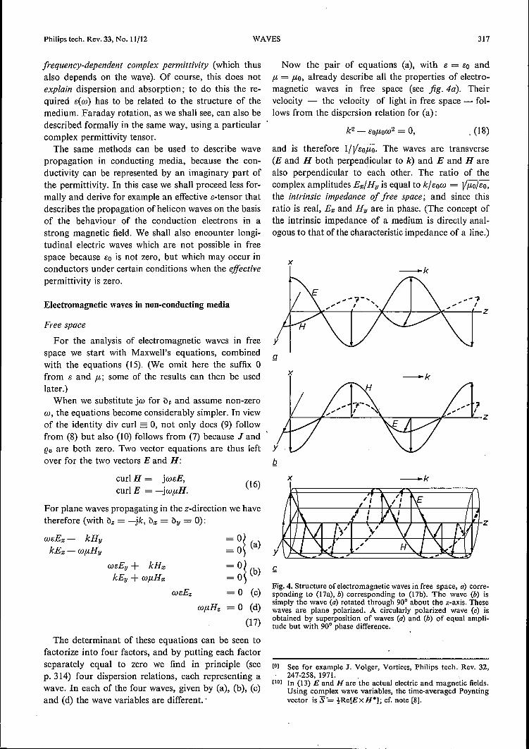
Now the pair of equations (a), with e = So and{h= {hO,already describe all the properties of electro-magnetic waves in free space (see jig.4a). Theirvelocity - the velocity of light in free space - fol-lows from the dispersion relation for (a):
. (18)
and is therefore I/Vso{ho. The waves are transverse(E and H both perpendicular to k) and E and Harealso perpendicular to each other. The ratio of thecomplex amplitudes Ex/Hy is equal to k/sow = V{ho/so,the intrinsic impedance of free space; and since thisratio is real, Ex and Hy are in phase. (The concept ofthe intrinsic impedance of a medium is directly anal-ogous to that of the characteristic impedance of a line.)
x-k
ax -k
(16)
Fig. 4. Structure of electromagnetic waves in free space, a) corre-sponding to (17a), b) corresponding to (17b). The wave (b) issimply the wave (a) rotated through 90° about the z-axis. Thesewaves are plane polarized. A circularly polarized wave (c) isobtained by superposition of waves (a) and (b) of equal ampli-tude but with 90° phase difference.
[D] See for example J. Volger, Vortices, Philips tech. Rev. 32,247-258, 1971. .
[10] In (13) E and H are the actual electric and magnetic fields.Using complex wave variables, the time-averaged Poyntingvector is S-= !Re[ExH*]; cf. note (8].

318 C. A. A. J. GREEBE Philips tech. Rev. 33, No. 11/12
The practical significance of the expression ItV Eoflo for thevelocity of light in free space is that, in the construction of asystem of units such as SI, although there is some freedom ofchoice with respect to EO and flo the combination I/VEo/ta mustalways be equal to the velocity of light.
Other solutions are obtained by applying a rotationto that of fig. 4a; k (or w) and E (or H) can be freelychosen. The solution of the equations (17b) is simplythe wave of (17a) rotated through 90° about the z-axis(fig. 4b). Any wave in free space can be described by asuperposition of such waves.One 'rather special case of superposition is the super-
position of (a) and (b) where Ex in (a) and Ey in (b) areof the same amplitude but differ by 90° in phase:
Ex = ±jEy. (19)
This is a circularly polarized wave (fig. 4c). The uppersign (+) represents a vector rotating clockwise, andthe lower sign (-) represents a vector rotating anti-clockwise, as seen by an observer looking in the +z-direction, and assuming w to be positive [111.
The end points of the vectors lie on a helix. The re-lation between the sense of this helix, the sense of rota-tion of the vectors and the direction of wave propaga-tion can best be formulated by adopting the conven-tion used in optics. In this convention a sense of rota-tion is defined as that seen by an observer receiving thewaves. Then the sense of the helix is the same as thatof the rotation of the vectors (in whatever direction thewave propagates), and this is by definition the sense ofthe circular polarization. According to this definitionthe upper sign in (19) represents left-handed circularpolarization for a wave travelling in the -l-z-directionand right-handed circular polarization for a wavetravelling in the -z-direction.The equations (17c) and (17d)would represent longi-
tudinal electric waves and longitudinal magnetic waves
Fig. 5. If a material has a different polarizability in two directions~ and C (see eq. 20), the ratios DI;/EI; and DI;/EI; are not equal.Hence D and E are no longer parallel to one another, unless theyhappen to be along the ~-axis or the C-axis.
respectively, but their dispersion relations, W8 = 0,wp. = 0, are not satisfied in free space (for co =1= 0). Forthis reason longitudinal electromagnetic waves cannotexist in free space.
For a medium whose electric and magnetic propertiesare described by (14), where 8 and p. are true constantsof the material and where a is zero, electromagneticwaves entirely analogous to those in free-space wavesare possible; their velocity is l/V8p. and the intrinsicimpedance ElH is JIïi!ë. Such media do not reallyexist but in certain cases - for example that of low-frequency waves in an isotropic lossless insulator - thewave propagation is well described in this way.
We shall now examine what happens when themedium is not isotropic.
Anisotropy; double refraction
Let us consider a crystal that is not equally polariz-able in all directions. The relation between D and Ecan now no longer be characterized by a single scalarquantity. We shall assume that an orthogonal coordi-nate system g, 'rj, 1;exists in which
DI; = 8lEI;' Dil = 8lE", D, = 83E" (20)
where es > 81; the polarizability is thus larger in the1;-direction than in the g,'rj-plane. We are then con-cerned with a uniaxial crystal in which the 1;-axisis theoptical axis. From (20) we can immediately conclude- see jig. 5 - that D and E are no longer parallel toeach other, unless they happen to be parallel or perpen-dicular to the 1;-axis.
For light propagated along the optical axis, the cal-culation of p. 317 can again be used, with 8 = 81. Forpropagation perpendicular to the optical axis, the cal-culation is also entirely analogous, except that in (17a),8 = 83 and in (l7b), 8= 81: we therefore get two waves,one polarized along the optical axis and the otherperpendicular to it, with different velocities.The situation becomes really interesting when we
consider plane waves whose k vector makes an angleother than 90° with the 1;-axis.Going back to Maxwell'sequations (7) and (8) we find, taking a coordinatesystem x,y,z in which k is parallel to the z-axis, andtaking B = p.H, J = 0, p. =1= 0 and w =1= 0:
kHy = wDx, wftHx = -kEy,kHx = -wDy, wftHy = kEx, (21)
0= De, Hz = O.
It follows that D, Hand k are perpendicular to oneanother. D and H are still transverse: the wavefrontsare D,H-planes. If D is taken perpendicular to the1;-axis (jig.6a) the situation is still quite unremark-able: E is again parallel to D and the wavehas the samenature as we have already encountered. If, however, D

Philips tech. Rev. 33, No. 11/12
is taken to be in the k,C-plane (fig. 6b) then D is neitherparallel nor perpendicular to the C-axis, so that E isno longer parallel to D (see fig. 5). The Poynting vectorS= Ex H is therefore no longer parallel to the wavevector k. Since Sgives the direction of the energy flowand therefore, in the case of a parallel beam, the direc-tion of the beam, the wavefronts lie obliquely to thisdirection (fig. 7). An unpolarized beam falling perpen-dicularly on the x,y-plane in fig. 6a and b (this beingthe surface of the crystal) is therefore split into a'straight-through' beam (fig. 6a) and an 'oblique' beam(fig. 6b): this is double refraction.
The permittivity tensor
We have seen that in an anisotropic material D andE are in general not parallel to one another (see fig. 5).It follows that, in a coordinate system x,y,z not paral-lel to the coordinate system !;,'Y/,C, used above, each
x
y
x
Hy
Fig. 6. Double refraction. In a uniaxial crystal, a plane wavewhose k vector makes an angle with the optical axis C, the vectorsD, Hand k (see eq. 21) are still perpendicular to one another, asin an isotropic medium. If D is perpendicular to the optical axisas in (0), then E is parallel to D and the Poynting vector S isparallel to k; if, however, D lies in the plane defined by k and Cas in (b), then E is not parallel to D and so S is not parallel to k,
WAVES 319
Fig. 7. A beam, i.e. a wave with boundedwavefronts, is propagated in the directionof the Poynting vector S. If k is not parallelto S (fig. 6b), the wavefronts are not per-pendicular to the beam.
k
component of D may depend on all the components 01
E. In general we must write:
D» = ~ SkiEl. (k,l = x,y,z) (22)
This applies also to a biaxial crystal for which threedifferent s's occur in (20). The two or three s's in (20)andthe nine ski's in (22) give the same linear relationship be-tween the physical vector fieldsD and E; ifyet anothercoordinate system is chosen, the nine quantities de-scribing this relationship will have other values. Such atensor relation between D and E is written:
D=sE, (23)
where s, thepermittivity tensor, is thus a property of thecrystal which, for each coordinate system x,y,z, is de-fined by another array
(
'SXX
Syx
Szx
sxz)SyzSzz
Sxy
Syy
Szy(24)
of nine scalar quantities.In such a crystal the electric state and therefore the
electric energy per unit volume UE are determined bythe values of Ex, Ey and Ez. In a change of state inwhich D increases by dD, the crystal takes up anenergy of E· dD per unit volume from the field (seep. 316) and UE thus changes by this amount so that
dUE = E· dD = L.SkIEkdEI'k.l
It follows thatvUErDEI = L.SkIEk,
k
and
[11] A right-handed coordinate system is assumed here as infig. 4. It is further assumed that all the wave variables areproportional to exp (+ jwt) and not to exp (- jwt), as issometimes done. We shall continue to use these conventions.
320 C. A. Á. J. GREEBE Philips tech. Rev. 33, No. 11/12
From this it can be seen that e is symmetrical:
Hence there are at most six different quantities in (24).The proofs that symmetries of the same nature mustexist for elasticity and piezoelectricity run along thesame lines.The description of a crystal by means of six constants
of the material en is satisfactory for static and forslowly varying fields. Losses and dispersion whichbecome important at higher frequencies are not en-compassed by this description. They can however beincluded in the formal framework of the permittivity,if the latter concept is extended in the followingmanner.
Complex and frequency-dependent permittivity
If, for an isotropic material, 13 is regarded strictly asa constant of the material, then D is everywhere and atevery instant (independently of the situation elsewhereand of previous events or states) given by the value ofE at the same place and the same instant. In otherwords, D = eE is a local, instantaneous relation. Inreality such a rigorous relation between D and E existsonly in free space. For example, when E varies veryrapidly, the polarization and therefore D in mostmaterials also usually varies at the same frequency butthe ratio of the amplitudes of D and E may well dependon the frequency and D often lags behind E. At a givenmoment D may thus depend not only on the value ofE at that moment but also on previous values. Such anon-instantaneous relationship will be accounted for,as usual, by regarding the expression D = eE as arelationship between the complex quantities D and E,where 13 is then a quantity that may be complex andfrequency-dependent:
13 = s'(ro) - je"(w).
Since a minus sign is conventionally used here, apositive value of e" indicates a lag of D behind E andthis implies losses, as can be seen by calculating themean energy dissipated by the dielectric per second andper unit volume, (ReE)(ReD), which is found to be1-we"EE*.
At zero frequency we must recover the original rela-tion between D and E: this means that 13"(0) must bezero and 13'(0) must be the permittivity for static fields.The complex representation and method of calcula-
tion thus allows us to take account of non-instanta-neous relations betweenD and E and so to describe los-ses (13" =1= 0) and dispersion (13' is a function of w). Non-local relations between D and E will not be consideredhere. Later on, the conductivity a in (14) will some-times also be taken as complex and frequency-depend-
(25)
ent. The permeability ft, on the other hand, will beconsidered here always as a real constant (and notcomplex as for example in problems related to electronand nuclear spin resonance).Analogously we shall hereafter consider that e in
(23) may be a complex and frequency-dependent tensor.Instead of (25) we must then have the symmetry rela-tion
(26)
if the material is lossless. This follows since the time-average of (ReE)' (ReD) can be shown to be
t jw ~ (ek I - elk*)EkEI*,kl
and in a lossless crystal this must be zero for all E. Atzero frequency the real part of e must again reduce tothe original tensor for static fields and the imaginarypart must again vanish. The relation (26) then reducesagain to (25).
The Onsager relations
The conclusion that the permittivity tensor e mustsatisfy the relation (26) is based on the assumption thatthe medium is lossless. It can be shown in quite adifferent way that certain relations must in any caseexist between the elements of e, whether there arelosses or not. However, other factors then have to betaken into account, e.g. whether or not the medium issubjected to a magnetic fieldHo. If this is the case (andif this is the only other factor involved), then
ekl(- Ho) = elk(Ho). (27)
These are the well known Onsager relations [12] appliedto e. Thus, if there is no magnetic field, e is symmetric,whether there are losses or not. Only if ekl is real does(27) reduce to (26) when Ho = O.The Onsager relations are applicable to the coef-
ficients of many kinds of linear relationships in physicsand engineering and are of a fundamental nature. Theyare based on the reversibility (in time) of micro-processes. They are valid only for coefficients relatingvariables that are conjugated in a prescribed manner.The derivation of the Onsager relations cannot bedealt with here.
Reversibility in a system of particles implies that all theparticles would retrace their paths exactly if at a given momentall the velocities were reversed. All external influences that areantisymmetrie in time must then also be reversed, for exampleelectric currents and magnetic fields (which can always beconsidered as deriving from currents). The only influence of thiskind mentioned in the foregoing was an applied magnetic field.
[12] See H. B. G. Casimir, Rev. mod. Phys. 17, 343, 1945.

Philips tech. Rev. 33, No. 11/12
Faraday rotationOn the basis of the symmetry relations we shall now
set up a very simple s-tensor with which the rotation ofthe plane of polarization in a constant magnetic field(Faraday rotation) can be formally described. Thequestion of how the form of the tensor depends on thestructure of the medium will not be discussed.Restricting ourselves to lossless media, we resolve e,
element for element, into real and imaginary parts.From (26) the real part is symmetric, the imaginarypart antisymmetric. We can therefore write:
where es is symmetric, ea is antisymmetric, and bothare real.Next, by a suitable rotation of coordinates, we re-
duce the s-tensor to diagonal form. It can be shownthat this is always possible for a real and symmetricmatrix. ea then remains antisymmetrie and real so thate takes the form:
(
BsIe s= 0
o
o 0) (0 Ba3 Ba2)o + j -Ba3 0 Bal.
BS3 -Ba2 -Bal 0Bs2o
In our previously considered isotropic case (free space)all the Bs'Swould be equal and all the Ba'Swould be zero.One of the simplest deviations from isotropy - all theBa'S zero but one of the Bs'S different from the othertwo - has also been discussed: this was the case ofthe uniaxial crystal (see 20) and it leads, as we haveseen, to double refraction. If we now take all the Bs'Sequal but make one of the Ba'S not zero:
(
BS
e = r jBa
Bso
~),Bs
wehave the tensor with which the Faraday rotation canbe described. We note, first of all, that according to theOnsager relations, Ba in (28) can be non-zero only if aconstant magnetic field Ho is present: for we must haveBa(Ho) = -Ba(-Ho). In the coordinate system x,y,z inwhich (28) is valid, the z-axis differs from the x- andy-axes: this must therefore be the direction of the mag-netic field. The simplest case in which (27) is satisfied isthat with Baproportional to Hz, so that its sign reversesif the field Hz is reversed. If the frequency goes to zero(25) must again be satisfied and so Ba must becomezero.Next we show that (28) leads to a rotation of the
plane of polarization. For a wave propagating alongthe z-axis, Maxwell's equations, with B = p.H, J = 0,ft =1= 0 and W =1= 0, lead again to the equations (21). Thewaves are thus purely transverse; from (21),D« and Hzare zero and (28) then shows that this is also the case
WAVES 321
for Ez. Combining (21) and (28) we find for the trans-verse components of E and H:
wBsEa; - kHy +jwBaEykEa;-wftHy
- 0 ~. - 0: ) (a)
(29)+ wBsEy + in; = 0, ~ (b)
kEy +wftHx = O. ~
The terms are arranged in the same way as in (l7a, b).The Ba term now, however, couples the pair of equa-tions (a) and (b), so that independent linearly polarizedEx,Hy-waves and Ey,Hx-waves are no longer possible.From (29) we find as dispersion relation:
(30)
We see here again what we already knew: propagationof undamped waves is possible only for real Bs andreal Ba. Eliminating Hy from (29) and using (30) leadsto:
Ex = ±jEy. (31)
We thus find a left-handed and a right-handed cir-cularly polarized wave with different velocities. For asmall difference in velocity (IBal « Bs), these waves, ifof equal amplitude, can be combined to give a plane-polarized wavewith a slowly rotating plane of polari-zation.The plane of polarization forms a helix whose sense
is the same as that of the circularly polarized wavewiththe smallest pitch, i.e. the slower ofthe two waves, thathaving the shorter wavelength. If the magnetic fieldhas a polarity such that Ba is positive, then the slowerwave corresponds to the upper sign in (30) and in (31)
(28)_ and is thus left-handed if it travels in the -l-z-directionand right-handed if it travels in the -z-direction(optical convention, ~ee (19) and the accompanyingtext); for negative Ba (reversed polarity of magneticfield) the reverse is true. For a given polarity of themagnetic field, the sense of polarization of the slowerwave, and consequently the sense of rotation of theplane of polarization (optical convention) is thusopposite for waves propagated in opposite directions;also, for both cases, the rotation reverses its sensewhenthe magnetic field is reversed.The situation is thus essentially different from that
with natural optical activity, e.g. in quartz or in sugarsolutions, where the sense of rotation. (optical con-vention) is the same in both directions. The above de-scription is therefore not applicable to natural opticalactivity. This follows, too, from the Onsager relationfor the field-free case: Bkl = BIk, which is inconsistentwith (28).
Returning to the magnetic rotation, the situation is

322 C. A. A. J. GREEBE Philips tech. Rev. 33, No. 11/12
drastically changed if I8a I becomes larger than 8s·
From (30) it then follows that for real W there is onereal k and one imaginary k. Only one wave is thereforepropagated; the other is cut off. Both are still circularlypolarized. This is the situation that obtains for heliconwaves as we shall see presently.
Electromagnetic waves in conducting media
Conductors obviously cannot support undampedwaves; the field E and the consequent currents J giverise to losses. However, the losses may be small if Jdiffers in phase from E by about 90°. Some examplesof both strongly attenuated waves and almost un-attenuated waves in conductors will now be discussed.
We assume that the current is carried by free elec-trons in a crystallattice, and also that the material hasno pronounced magnetic or dielectric properties; forconvenience we put B = /-HB and D = 81E, and as-sume that the f-ll'S and the 81'S are little different fromf-l0 and 80. The cardinal question is now: what is therelation between J and E? In 'normal' circumstancesin conductors we have:
J=aE,
where a is a constant of the material, the conductivity.Equation (32) can also be used under less normal cir-cumstances, for example at very high frequencies, butthen a is a complex quantity, possibly frequency-de-pendent. Provided (32) is applicable, in one way or theother, a simple procedure enables us to make use ofthe results of previous calculations. Substitution off-l1B, 8lE and aE for B, D and J respectively in (7)and (8) yields:
curl H = (jW81 + a)E,curl E = -jwf-l1H,
and these equations are equivalent to (16) if wereplace 8 in (16) by Beff, an effective dielectric constant:
Beff = 81 + a/jw.
We note here that Beff could assume the value zero ifthe two terms should compensate each other, In thatcase the dispersion relation W8 = 0 for longitudinalelectric waves would be satisfied (see 17c); we shall seelater, that such waves are indeed possible. First, how-ever, we shall give some examples in which 8eff is stillnon-zero and the waves still transverse (17 a,b).
In metals, the term 81 in (33) can be neglected up tovery high frequencies, so that 8eff is given by
8eff = afjw.
This can be seen from the fact that, while the permit-tivity of the material 81 is at most a few orders of
magnitude larger than 80 (8.855 X 10⁻¹² F/m), the valueof a/wat room temperature in copper (for example)has even at microwave frequencies a value of 10-2 Firn(a ~ 108Q-1m-l, W ~ 1010S-l),
The skin effect
Let us consider a metal of conductivity ao. Followingthe simple procedure mentioned above, we replace 80
in (18) by the 8cft of (34), putting a = ao, and we putf-lO= f-ll. We then get the dispersion relation for trans-verse waves in a metal:
(35)
or
k = ±(l - j)Vwf-llao/2. (36)
(32)
For real w, (36) represents strongly attenuated travellingwaves of the type shown in fig. 3b; in particular thereal and imaginary parts of k are equal in magnitude.This implies a wave of the type shown in fig. 8. Suchwaves can exist only in the neighbourhood of thesurface of a metal. They propagate inwards from thesurface and die out within a small distance, thepenetration depth or skin depth. At high frequencies theskin depth is very small.
The above is a description of the skin effect at highfrequencies (or in very thick wires). An a.c. currentthrough a conducting wire is not distributed uni-formly over the whole cross-section of the wire as isa direct current: the amplitude and phase of thecurrent density are functions of distance from thesurface and at high frequencies the current is confinedto a thin layer under the surface. To discover thedistribution of the current and its magnetic field (seeinset, fig. 8) it is only necessary to consider a layer ofthickness equal to a few times the penetration depth.If the penetration depth is small compared to the wirediameter, the surface can be considered as flat and inthis case the current and field distribution can be cal-culated from (36), and the result is that shown in fig. 8.
For the values used above, ao = 108 Q-lm-I,W = 1010 s-1, and f-ll = f-lO= 4nX 10-7 Hjrn, the clas-sical skin depth Ók == kl-l = V2/Wf-lLaO is only 1 fLm.
The intrinsic impedance Ex/Hy of the metal for atransverse wave is found from (17a) and (36):
Ex/Hy = wf-ll/k = ± (I + j) VWf-ll/2aO.
Because the value of ao/w is so very much larger than80, the modulus of Ex/Hy is many orders of magnitudeless than Vf-lo/8o, the intrinsic impedance of freespace. This implies a virtually complete mismatch be-tween free space and metal. For this reason an electro-magnetic wave in space incident on a metal surface isalmost completely reflected (see p. 341/42).
(33)
(34)

Philips tech. Rev. 33, No. 11/12
1.------------------------------,
0.6
O.I._-t-_
",' : .....,1II
-z
Fig. 8. Electromagnetic wave in a metal according to the disper-sion relation (36) for real w: the waveform at a given instant(solid curve), a quarter of a period later (dashed curve) and theamplitude of the wave as a function of z (dotted curve). Thecurves represent the functions exp( - O() cos 0(, exp( - O() sin 0( andexp( - O() respectively, where 0( = Z/Ok and Ok = V(2/WftlaO) is theclassical skin depth. The vertical scale represents a wave variablein arbitrary units, e.g. the current density Jo; or the magnetic field,Hy• (The field Hy has a quarter of a period phase lag with respectto Je, as follows from (7) with D = 0 and k = (1 - j)/Ok') Theinset diagram gives the relative directions of J, Hand k in acylindrical wire carrying a high-frequency current. The plane-wave solution discussed is of course only valid here if Ok is muchsmaller than the wire diameter.
Helicon waves
In a conductor with a high concentration of high-mobility electrons (e.g. a pure metal at low tempera-ture) situated in a strong magnetic field, circularlypolarized waves can propagate in the direction of themagnetic field. Under certain circumstances, thesewaves are practically unattenuated and propagate atan extremely low velocity. These waves are the heliconwaves noted earlier. Their existence was predictedtheoretically [13] in 1960and in 1961 theywere demon-strated experimentally [14]. There is a certain kinshipwith the Hall effect: as in that case, the current andelectric field are not parallel - indeed, if the magneticfield and the mobility of the charge carriers are largeenough, current and field may be almost perpendicularto one another.
WAVES 323
It follows from this that J and E are no longer linkedby a scalar relation such as (32), but by a tensorrelation. Table I shows how in the normal situation, inthe absence of a magnetic field, the usual scalar relationJ = (joE is obtained. The equation (1.1) in the tableexpresses the fact that the conduction electrons (charge-q, mass m, concentration n) are accelerated by thefield but also - because of collisions - are subject toan averaged frictional force; Vd is the resulting meandrift velocity of the electrons. The 'coefficient of fric-tion' is the reciprocal of the relaxation time -r approx-imately equal to the mean time between collisions.When the left-hand side is neglected - justifiable if thefrequency is not too high - then making use of (1.3),(1.4) and (1.6) we find the usual relation (1.5); /he isthe 'mobility' of the electrons.In order to include the effect of a static magnetic
Table J. Summary of the theory of conduction in metals (Drude)at low frequencies ('w = 0') and in the absence of a magneticfield. III mass of charge carriers, 11 their concentration, Vd driftvelocity, 7: relaxation time. The formulae are written for negativecharge carriers (electrons) of charge -q. For positive chargecarriers of charge +q, the signs in 1.2 and 1.4 and thesign of qEin 1.1 would be reversed; with this convention, q, ft and ao arethus always positive. For further explanation, see text.
mVd = - qE - mVd/-r (1.1)w=o
+Vd = -!-leE (1.2)
J= -nqvd (1.4)/he = + qtlm (1.3)0.
I Jt
J = (joE (1.5)ao = + nq/he = nq2ï/m (1.6)
field, a term representing the Lorentz force has to beadded to the right-hand side of (1.1):
m;'d = -qE - qVd X Bo - mna]», (37)
Bo is the static magnetic flux density. We shall presentlystudy waves that propagate in the direction of Bo, orin the opposite direction, and we therefore choose acoordinate system with the z-axis in this direction(Boz = Bov = 0, Boz = ± Bo). If the vector equation(37) is written out as three equations for the com-ponents of E and Vd, we find (because Boz = Bov = 0)
[13) O. V. Konstantinov and V. I. Perel', Sov. Phys. JETP U,117,1960.P. Aigrain, Proc. Int. Conf. on Semiconductor Physics,Prague 1960, p. 224. ,
[14) R. Bowers, C. Legendy and F. Rose, Phys. Rev. Letters 7,339, 1961.

324 C. A. A. J. GREEBE Philips tech. Rev. 33, No. 11/12
two équations in the transverse components Vdx', Vdy,Ex and Ey in which the magnetic field appears, andone equation in Vdz and Ez which is independent of theother two and in which the magnetic field does notoccur. The equation in Vdz and Ez is of no interest to usand will not be treated further. Neglecting the left-hand side again and making use of (I.3) then for thetransverse components, instead of (1.2) we find:
Vdx = -{leEx - f3VdY,(38)
wheref3 = {leBoz. (39)
Equations (38) and (1.4) and Maxwell's equations leadto the wave phenomena called helicon waves. Beforegoing further we should note that the quantity f3- which for electrons is the opposite of the Hall ratio(see fig. 9) - is a kind of quality factor: only for1f31» 1 are the electric field and the drift velocity (i.e.current) nearly perpendicular to one another, thecondition for virtually unattenuated helicon waves. Itcan be seen that this condition is only satisfied inquite extreme circumstances: for example, in a fieldBo = 1T = 1Vs/m2 = 10000 gauss, we must have{le» 1m2/Vs, whereas in copper at room temperature{le is only about 6 X 10⁻³ m2/Vs. Indeed, the first heliconexperiment [14] was done with exceptionally pure so-dium at 4 K: f3 was ~ 40 for Bo = IT, so that{le ~ 40 m2/Vs.
Solving (38) for Vdx and Vdy and using (1.4) yields atensor relation between J and E instead of (1.5):
J= C1E,
where the tensor C1is given by:
C10 (1 -f3)C1= 1+ f32 +f3 1 ;
x
E~ _ Ex ®Bo
~ -arcfan (-(3)_L__ ~ y
Ey
Fig. 9. Hall effect. The quantity f3 (eq. 39) for electrons is equalbut opposite to the tangent of'the Hall angle, i.e. the angle be-tween the direction of the electric field and the current. This canbe seen directly by putting Vdy = 0 in (38), i.e, by choosing thex-axis in the direction of the current. Equation (38) then givesEy/Ea: = -p. In the diagram Bo is directed along the positivez-axis (into the paper); Bo. and f3 are thus positive, while Ey/ Ea:is negative.
C10is the conductivity (1.6) when there is no static mag-netic field.
The dispersion relation for helicon waves propagatingalong the z-axis can now be easily derived because ofthe following. '1) We consider good conductors for which we maywrite Seff = C1/jW.2) The s-tensor that then follows from (40):
(
Serf seeff = .
-JSeff a
jSeff a) C10 (1eeff s = jw(1 + f32) +f3
-f3)1 '
(41)
has the same form as the transverse part of (28),although eeff S = C1o/jw(1 + f32) is no longer real forreal w (whereas eeff a = f3ao/w(1 + f32) is still real).3) The calculation based on (28) and using (29) whichleads to (30) and (31) is straightforward and is there-fore also applicable for Ss and ea not real.
Application of (30), with {l = {l1, therefore yieldsthe required dispersion relation. The result is:
w = ± f3 + j k2.{llaO
(42)
The tensor (41) satisfies the Onsager relations (f3changes sign with Boz) but no longer represents losslesspropagation, as was to be expected, because Seff s is nolonger real. The medium is however virtually losslesswhen 1f31» 1 because the real quantity Seff a in (41)then dominates the imaginary quantity Seff s- In thissituation (1f31 » 1) the properties of helicon waves aremost clearly manifested. The term j in (42) can then beneglected and we find, using (I.6) and (39):
(40)(43)
For real w we find a real k, which means travellingwaves, for the upper sign (+) if Boz is positive. Thiscorresponds to the upper sign in (31), i.e. to waves inwhich thevectors rotate clockwise as seen by an observ-er looking in the -l-z-direction. This is true for wavespropagating in both directions along the z-axis (k > 0and k < 0); seefig. 10. The sense of rotation using theoptical convention (see p. 318) is thus, as in Faradayrotation, opposite for waves in the two directions, andreverses if the magnetic field is reversed. For positiveBoz the waves in which the vectors rotate anticlockwise(for an observer looking in the +z direction) haveimaginary k and are thus cut off. The whole of thediscussion above has been based on the assumptionthat the charge carriers are elèctrons; ifthe conductionwere to take place via holes, the senses of rotationwould all be reversed.

The fact that ao/w is so many orders of magnitudelarger than EO implies that the intrinsic impedance of ametal for helicon waves - as for the classical skineffect 'waves' - is many orders of magnitude less thanthat of free space for conventional electromagneticwaves. From (29a) and (42), neglecting losses:
Ex/Hy = Wftl/k = V/3ftl/(ao/w)« Vfto/Eo. (44)
(Although 1/31 » I, it is negligible compared to thevery high value of the ratio of ao/w to fa.) We thereforeagain have a complete mismatch between the mediumand free space, so that both normal electromagneticwaves in free space and helicon waves in the medium
H /, are almost completely reflected at the interface.- - - - - - - - - L -l- As a result, in a configuration like that shown in
"A Ih,..-\- =r: -r--If-+--I''----¥----1L__-\--.------.-+-F-+-z fig, IJ, stan din g waves can be se t up whose atten ua ti0nis
)1.~~/~~~~~--~~~~ny
Philips tech. Rev. 33, No. 11/12
xH -k-Bo
#-~~_L-t_-+-~-.~~-.~-L-J_-4~~+z
J~~----_4+-~+-~------~Ijly
x k- -Ba
H
Fig. 10. Helicon waves moving in the direction of the magneticfield (upper diagram, k parallel to Bo), and opposite to the magnet-ic fjeld (lower diagram, k in opposite sense to Bo). The blackcurves represent the current-density wave (1) at a given instantand the red curves the J wave a quarter period later. In the upperdiagram, the wave moving to the right, H is in phase with J; inthe lower diagram, the wave moving to the left, H is in antiphasewith J. The electric field E is many orders of magnitude smallerthan in free space for the sarne H (see eq. 44), and is of littleimportance. The diagrams refer to conduction with negativecharge carriers (electrons); for hole conduction the vectors rotatein the opposite direction. Helicon vectors rotate in the samedirection as the corresponding charge carriers in cyclotron reso-nance in the same magnetic field.
Helicon waves exhibit a strong dispersion: the phasevelocity v = wik, which from (43) is proportional to kor Vw, can have widely differing values, depending onthe frequency. In particular the velocity can beexceedingly low. For example, in a metal withn = 6x 1028 m-3 in a field of I T (10000 gauss), ahelicon wave of frequency 17 Hz (w = 100 S -1) has awavelength of 6 mm and hence a velocity of 10 cm/so
The term j in (42) represents the attenuation. Fromthe form of (42) it can be seen, once more, that 1/31 is akind of quality factor. For a given medium (here thisincludes the value of Ba), 1/31 is independent of W. If themedium satisfies 1/31» I, the attenuation per wave-length (or per period) is just as small for low-frequency(slow) waves as for high-frequency fast waves.
At very high frequencies the left-hand side of (37)can no longer be neglected. It is found that the fre-quency at which this term begins to play a significantrole lies in the neighbourhood of Wc = qBo/m, thecyclotron resonance frequency. This is the angular fre-quency at which electrons in a magnetic field executea circular or helical motion. For w « Wc, the heliconwaves behave as described above.
WAVES 325
Fig. 11. Schematic diagram of an arrangement for a heliconexperiment. A sample plate in a magnetic field perpendicular tothe plate is provided with crossed coils. As a result of their cir-cular polarization, standing helicon waves excited by one of thecoils can be detected by the other coil. (In practice the primarycoil is wound uniformly over the whole length of the plate.)
determined entirely by /3. For example under the sameconditions as above (n = 6x 1028 m-3, Ba = I T) in aplate of thickness 3 mm (= À/2), standing waves of17 Hz can be expected.
In helicon experiments the sample is usually arrangedwith a primary coil and a secondary coil as in fig. l l .If a d.c. current is switched on or off in the primary, aseries of standing helicon waves are excited and thecorresponding damped oscillations induced in thesecondary can be observed (fig. J 2). Crossed coils areparticularly well adapted for the experiment: the onlycoupling between them is via the (circularly polarized)helicon waves.
By means of such experiments, the elements of thea-tensor and hence the Hall constant and the magneto-resistance [15] can be determined relatively easily andvery accurately as functions of Ba [16]. The deterrnina-
(15] These are (lxy(Bo)1 Bo and (lxx(Bo) respectively, where (lxx and(lxy are the elements of e (the inverse of the tensor a) whichexpresses E in terms of J through the relation E = eJ.
[16] R. G. Chambers and B. K. lanes, Proc. Ray. Soc. A 270,417,1962.M. T. Taylor, J. R. Merrill and R. Bowers, Phys. Rev. 129,2525, 1963.See also E. Fawcett, Adv. Phys. 13, 139, 1964.

326 C. A. A. J. GREEBE Philips tech. Rev. 33, No. 11/12
tion of these quantities by conventional methodsusually requires difficult precision measurements ofvery small resistances and voltages between accuratelylocated contacts. Helicon measurements are madewithout contacts on the sample.
1------0.5 5-------+-1
Fig.12. Voltages induced by helicon waves, after R. Bowers,C. Legendy and F. Rose [141. The diagrams show the voltagesacross the secondary coil (see fig. 11) as a function of time, afterinterruption ofthe primary current, with the sample in a magneticfield of strength (from top to bottom) 0 Oe, 3600 Oe, 7200 Oeand 10800 Oe. (In this first helicon experiment, the sample wasnot of plate form as in fig. 11 but a cylinder of diameter 4 mm,and the coils were not crossed.)
Two complications that can arise with helicon waves shouldbe mentioned. These do not come within the framework ofpurely local relations, characterized by effective e's and e's towhich we have previously confined ourselves (see p. 320).
Firstly, there is the absorption arising from Doppler-shiftedcyclotron resonance. The electrons responsible for conductionmove in all directions through the metal at a high velocity, theFermi velocity VF (not to be confused with the drift velocity Vd).An electron with a Fermi velocity in the direction of the heliconwave runs through the wavefronts and is thus subject to analternating field of frequency kVF (the velocity of the slow heliconwave is neglected here). If kVF is equal to Wc, the electron under-goes cyclotron resonance and so absorbs energy from the waveand attenuates it. If kVF is greater than Wc then there are someelectrons moving obliquely to the wave which come into reso-nance. For a given BD, there is thus an absorption edge atk = Wc/VF. Measurement of this absorption edge in single crys-tals for various direction of BD with respect to the crystal axesyields data on the anisotropy of the Fermi velocity and henceinformation about the shape of the Fermi surface [171.
Secondly, there is the question of 'open cyclotron orbits'. Ina metal with a simple Fermi surface (e.g, an alkali metal) in amagnetic field, the momentum vector of an electron describes aclosed orbit on the Fermi surface. In metals such as copper, silverand gold, however, the Fermi surface is so anisotropic that incertain directions the cyclotron orbits are 'open'. Because of thisthe helicon waves may be plane-polarized and strongly attenuat-ed. This effect is also used for the study of the Fermi surface [181.
Reflection and transmission of optical waves in metals
We shall now leave situations involving magneticfields to enquire what happens when the frequency ofan electromagnetic wave is raised to the optical region.Important changes occur in the skin effect, primarilybecause the term m~d in (1.1) can no longer be neglected.Instead of (1.5), with ~d = jWVd we find:
1 = aoE/(l + jorr).
Neglecting m~d in (1.1) is clearly justified only whenon« 1. Let us now assume that the frequency is sohigh that w-r» 1; there is then an effective conductivity
aeff = ao/jw-r = -jnq2/mw, (45)
which is purely imaginary so that there are no losses(1 and E differ in phase by 90°). Substituting (45) forao in (35) gives the dispersion relation:
(46)
Since k is imaginary, the waves are evanescent (fig. 3c,for real w). As with the classical skin effect, these'waves' are restricted to a thin layer at the surface ofthe metal. When electromagnetic waves are incidenton such a surface, it follows that no power can betransmitted through the metal and there are also nolosses; the waves are reflected completely. The shinyappearance of most metals is explained in this manner.At still higher frequencies the term cl in (33) can no
longer be neglected. This means that we have anadditional term cl/.t1W2 in (46):
k2 = clf.HW2 - f.tlnq2/m = clf.tl(W2 - wp2),
where(47)
is called the plasma frequency. This is a critical fre-quency: for W < Wp, k is imaginary so that the wavesare evanescent; for w > Wp, k is real so that the wavesare propagated through the metal. In the first casethere is complete reflection at the surface; in the secondcase there is partial reflection and partial transmission,dependent on the ratio of the intrinsic impedances ofmetal and free space (see Part III of this article). Thisimpedance ratio passes through the value unity in thetransition region, around the plasma frequency, andthis implies zero reflection and 100% transmission.
Philips tech. Rev. 33, No. 11/12
For most metals Wp lies in the ultraviolet. Withn = 6x 1028 m-3, BI = BO, and the usual values forthe electronic charge q and mass m, we findWp ~ l.4x 1016 S-l which corresponds to a free-spacewavelength of 140 nm. In this way the transparency ofalkali metals in the ultraviolet region can be under-stood [191.
Longitudinal electric waves in conducting media
Introduetion of an effective dielectric constantBelf = BI+ a/jw allowed us to make use of (16) forthe problem of electromagnetic waves in conductors.For plane waves propagated in the z-direction wearrived at (17) and it was noted that longitudinal elec-tric waves would be possible if Belf were to be zero. Itcan in fact be seen from (17) that if
Berr = BI + a/jw = 0,
then all components of E and H in (17) must be zeroexcept Ez. (It follows directly from (8) that all magneticcomponents must be absent in a wave with a longi-tudinal electric field, since longitudinal vectors all havezero curl). Now BI and a themselves are not zero in(48), so that not only E but also D and J have lon-gitudinal components. Since we also have ()z =1= 0 itfollows that the divergences of D and J (()zDz and()zJz), and hence (!e and £le (see (10) and (11)), areneither ofthem zero. These waves are thus characterizedby fluctuations in charge density: the electrons bunchtogether and disperse again. This is different from thecase of purely transverse waves, where the charge den-sity is everywhere zero (local electroneutrality): thedivergence of a transverse vector is zero.
In what circumstances is the dispersion relation (48)satisfied? For real conductivity, a = ao, we have forthe first time the situation that W cannot be real; W
must be purely imaginary, W = jaO/B1, and k is com-pletely arbitrary. Any charge distribution (!e(Z) withits corresponding field therefore dies away exponent-ially (see fig. 3g, h, j). The characteristic time for thisprocess is Oe = W1-1 = Bl/aO, the dielectric relaxationtime. For metals Ot has no physical significance:Bl/aO ~ 10-11/108 = 10-19S and, for processes takingplace in such a short time, the assumption that a equalsao is certainly incorrect. Certainly at radio frequencieswe can conclude that there is always local electro-neutrality in metals. In semiconductors, however,local space-charge variations do play a-role and Ot isan important quantity as we shall see presently.
In media and under circumstances where Wo» 1(e.g. in metals at optical frequencies) the conductivity ispurely imaginary, as we sawearlier (see 45). Lon-gitudinal waves 0f._ie~Ifreqyency are then possible, forsubstitution of (45) in (48) gives:
.WAVES 327
BI - nq2/mw2 = 0,so that
(48)
We see that the plasma frequency (47) is not only thecritical frequency for the propagation of transversewaves but it is also the frequency at which longitudinalwaves can exist, if Wo » 1. As with dielectric relaxation,k is arbitrary. Such waves do not transfer energy: thePoynting vector S= Ex H is zero because there are nomagnetic fields.The plasma frequency is a quantity continually encountered
in 'plasma physics', which is the basic discipline for a number ofquite diverse subjects such as travelling-wave amplifiers, astro-physics and controlled nuclear fusion. A plasma is a mediumwhose behaviour depends primarily on the charge and mass ofthe charge carriers and in which collisions play only a minor role.(Helicon waves are thus waves in a plasma.) The term was in-troduced in the twenties by Irving Langmuir, in connection withhis investigations into gas discharges, to describe a dilute,strongly ionized but electrically neutral gas [20]. In this workLangmuir discovered that, surprisingly, electrons injected intothe plasma rapidly came into thermal equilibrium with theplasma in spite of the very long mean free path. High frequencyoscillations of the plasma would explain this. Such plasmaoscillations had in fact been observed earlier by F. M. Pen-ning [21J. The frequency found by Penning was 108 to 109 Hz,corresponding to wavelengths of several decimetres. From (47)this would imply an electron density of the order of 1017 m-3,which is indeed typical for low-pressure gas discharges such asthose used by Penning.
Summarizing we can say that local space-chargefluctuations die away exponentially in a time r, ifelectron collisions play the dominant role (a = ao), oroscillate at the frequency Wp if collisions can be neglect-ed (wo» 1). For charge variations that are very steep(large k) it is necessary to take into account a phenom-enon that has not yet been discussed in this article,and which is of a non-electromagnetic nature: thediffusion of the electrons from regions of high concen-tration to regions of low concentration. We shall nowlook into this, but only for the case of low frequencies.The extra electron current due to diffusion is+D« grad n (Dn = diffusion constant). The concentra-tion n has a gradient only because of deviations fromthe equilibrium concentration no and the net localcharge density corresponds exactly to these deviations(!e = -q (n - no), so that grad n = grad (n - no) =
[17] E. A. Stern, Phys, Rev. Letters 10, 91, 1963.M. T. Taylor, Phys, Rev. 137, A 1145, 1965.
[18J S. J. Buchsbaum and P. A. Wolff, Phys, Rev. Letters 15,406, 1965.C. C. Grimes, G. Adams and P. H. Schrnidt, Phys, Rev.Letters 15, 409, 1965.See also the article by Fawcett [16].
[19] R. W. Wood, Phys. Rev. 44, 353, 1933.C. Zener, Nature 132, 968, 1933.
(20] I. Langmuir, Proc. Nat. Acad. Sci. 14, 627, 1928.(21J F. M. Penning, Nature 118, 301, 1926, and Physica 6, 241,
1926.
328 c. A. A. J. GREEBE Philips tech. Rev. 33, No. 11/12
=-e:' grad ee.The total electric current density there-fore becomes:
J = aoE - D« grad ee. (49)
For plane longitudinal waves this caneasily be reducedto the form (32). With (grad ee)z = -jkee andee = ()zDz = -jks1Ez, we find:
Jz = (oo + k2 SlDn)Ez.
The factor in the bracket is again an effective conduc-tivity. Together with (48) it leads to the followingimproved dispersion relation for longitudinal waves:
Forwaves of infinite wavelength (k -+ 0), we find againthe relaxation behaviour discussed above; from (50)we find - as was to be expected - that for shorter,steeper waves (steeper charge variations) the relaxationis more rapid.We now consider infinitely slow waves (w -+ 0)
instead of infinitely long wavelengths. From (50) wefind that these are exponential charge distributionshaving the characteristic length kj-
1 = VS1Dn/ao == VDn-C•. This is the Debye-Hückellength An. Asurfaceinside a conductor covered with a uniform charge isscreened by a layer in which the charge density at thedistance An has fallen off by a factor e.
In the Debye and Hückel theory [221 of the conduction ofelectrolytes the quantities 1:. and J'D both play a role. Generallyspeaking, a positive ion is surrounded by a cloud of negative ionsof radius ÀD; the positive ion experiences a frictional force,because relaxation causes the cloud to lag behind the positiveion when this moves.
In (50) we first neglected the third term and then we neglectedthe first term. Suppose we now neglect the second term (ao _,. 0):el then also disappears from the equation and all purely electricvariables have vanished. With wel = 1:D, and kcl = LD,(50) reduces to the familiar relation common to diffusionproblems, LD = VD1:D.
Elastic waves
Elastic waves in solids can be of a very complexnature. We shall introduce only a few elementaryelastic waves here, but in passing we shall see howcomplications can easily arise. Later on we shall con-sider coupling between the waves introduced here andelectromagnetic waves, and we shall then see that thiscan give rise to some remarkable effects in piezo-electrics.We shall find in this section the well known result
that the wave velocity (the velocity of sound) is highestin rigid and light substances. More specifically, in sub-stances with a high resistance to pressure and tensionbut not to shear, longitudinal waves are fast but trans-
verse waves are slow; in those with a high resistance toshear as well, transverse waves are also fast. In mostsubstances the velocities of longitudinal and transversewaves do not differ greatly. Gelatine is an example inwhich transverse waves are much slower than longitu-dinal waves.In elastic waves we are concerned with non-uniform
displacements of volume elements, i.e. deformation of' :the material; this implies internal mechanical stressesin the material which, in turn, react on the displace-ments. The linear equations (algebraic and differential)between these quantities again define the waveproblem.
(50)Displacements, strains and stresses
Starting with the displacement II of each point of thematerial from its equilibrium position x,y,z, in which11 is thus a function of x, y and z, the six strain com-ponents SI, S2, ... S6 are defined as follows:
SI = Sa;a;= Oa;Ua;,S2 = Svv = OyUy,S3 = Szz = OzUz,
S4 = SyZ = ()yUZ + OzUy,S5 = Sza; = ()zUa; + oa;uz, (51)S6 = Sa;y = Oa;Uy+ OyUa;.
There is deformation of the medium only if the dis-placement 11 is a function ofthe coordinates; ifit is not,either there has been no displacement (11 = 0) or themedium has been displaced as a whole (11 i= 0). Thestrain components are therefore derivatives of 11. SI,S2 and S3 give the extensions in the x-, y- and z-direc-tions (fig. J3a) and S4, S5 and S6 give the shear(fig. l3b); the latter consist of combinations of thederivatives such as ()yUZ + OZUy because OyUZ =1= 0 alonedoes not necessarily imply deformation as is explainedin fig. 13.
The internal stress is the force per unit area exertedby materialon one side of a given internal plane onmaterialon the other side. In tension or compressionthe force is directed normally to the plane, in sheartangentially (fig. 14). We can therefore expect ninestress components Te», Ta;y, ... Ta; the first suffixindicates the direction of the force and the second thenormal to the plane considered. The net couple oneach volume element must be zero, which reduces thenumber of components to six (because Tyz = Tzy,Te» = Ta;z, Ta;y = Tya;); this is explained in fig. 15.There remain the six stress components:
Tl = Ta;a;,T2 = Tyy,T3 = Tee,
T4 = Tyz = Tzy,T5 = Tza; = Ta;z,T6 = Ta;y = Tya;.
In equilibrium the net force on each volume elementmust also be zero which means that the stress field is[221 P. Debye and E. Hückel, Phys. Z. 24, 305, 1923.
L. Onsager, Phys. Z. 27, 388, 1926.

Philips tech. Rev. 33, No. 11/12
homogeneous (fig. 15). We shall return to this later(p.330).Provided the strains are small, they are linearly
related to the stresses (Hooke's law):
(k,t = 1,2, ... 6).I
The 36 coefficients Ckl are called the elastic moduli (orstiffness constants). As in the derivation of (25) (andassuming that any changes in Sand T are so slow thatthe Ckl remain real) it can be shown that the elasticmoduli are symmetric (Ckl = Clk) if no mechanicalenergy is transformed into other forms of energy. (Thework done on the medium per unit volume in theelastic case is ~TkdSk. This is explained in fig. 16).In the case of greatest anistropy (triclinic crystal) westill need however 6 + t X (36 - 6) = 21 differentconstants to describe the elastic properties of the ma-
y
r- -,I II II V(XI
O/XII
I II IL _J
WAVES 329
(52)
terial. Clearly complications can arise all too easily.Crystal symmetries, however, restrict the number ofindependent constants and with a favourable choice ofcoordinate system this restrietion becomes apparentthrough the appearance ofmany zeros and many equal-valued constants. In particular, isotropic material hasonly two independent constants; the array of constantsthen has the following form:
SI S2 S3 S4 Ss Sa
Cll CI2 C12 0 0 0CI2 Cll C12 0 0 0CI2 CI2 Cll 0 0 0 (53a)0 0 0 C44 0 00 0 0 0 C44 00 0 0 0 0 C44
Zz
Uy,.,--f-!l':', '--,-7, ,
I 'I '
,I,
I .... Uy, T',Uz, I ..,.... , ,........I ,,
I.... ....I ., U~
I... I........t. II
,uy ""'J
y-~/-~,r--7---YI I II I I, , IL.L..._-;':o+~'--'
uy
Fig:13. Various types of deformation: a) extension, b) shear. In (a) a volume element isextended in the x-direction; Ï)",11", is positive. A negative Ï)",11", means a compression in thex-direction. By definition Ï)",11", is the first deformation component S"'''' = SI. In (b) layersperpendicular to the z-axis are displaced with respect to each other in the y-direction; Ï).uv ispositive. A positive or a negative value of Ï).lIv does not always imply deformation, however:in (c), where a volume element has been rotated without deformation, Ï).lIv is also positive.But Ï)vll. is equally large and of opposite sign. If the sum Ï)vll. + Ï).lIv is not zero, the elementdoes undergo deformation. This is the deformation component Sv. = S4. Analogously,S2 = Svv, S3 = S zz and Ss = S''''' SG = S"'v.
x
.Q
y
z
Fig. 14. Tensile stress and shear stress. The materialon the +xside of an elementary area perpendicular to the x-axis exercisesa force on the materialon the -x side. The stress componentsT",,,,, Tv", and T.", are by definition the X-, y- and z-componentsrespectively of that force per unit area of the elementary area.T",,,,is a tensile stress (T",,,, > 0) or a compression stress (T",,,, < 0).Tv", and T.", are shear stresses. The stress components T",v, Tvu.T.v, Tee, Tv. and Te« are defined analogously. See also fig. 15.
y y
Tyx{x)
!Xix,) !xxfx2)
x, X2
T..x!xy
7;y
TYx
xx
Fig. 15. a) In equilibrium the net force on a volume element iszero. Since the force per unit area exerted on the volume elementon its face that faces left (or down or backwards) is equal butopposite to the stress there, we have T",,,,(x2) is equal to T",,,,(xl),Tv",(x2), to Ty",(Xl), etc; in other words the stress field is uniform.b) The uniform stress field Tv", exerts a couple on the volumeelement. In equilibrium, this must be balanced by the oppositecouple resulting from T"'v.1t follows that T",v = Tv"" and equally,Tv. = Tzv, Tee = Te z- There are thus six independent .stresscomponents: Tl = T",z, T2 = Tvv, T3 = Tee, T4 = Tvz, Ts = Tee,TG = Tzv.

330 C. À. A. J. GREEBE
where cu. CI2 and C44 are related as follows:
(53b)
One or two comments will serve to illustrate thesignificanee of the constants en, CI2 and C44 in the
~y~z IQ
7iLlyLlz
o 1 2--~""'!
I :
---+----.'-.;.-! ---- __ - X
fxxLlyLlz__L...!
01 2 012--j .....:
I :, :,IIIIII II ,
! ::,L..l.__;__-} __.J •••••• i
i J+Llx
7iLlyLlz
Fig. 16. Tensile stress and strain are assumed to be present hereonly in the x-direction. a) The work done on the material to theleft of the element of area ûyûz, when it is deformed from thestate 1 (dashed) to the state 2 (dotted) is:
T",,,,ûyûz(II,,,(2) - 11",(1» = TldllxD.yD.z.
Solid line: the undeformed state (0).b) The work performed on the volume element .ó.x.ó.yûz is:
Tl(dll",(x + .ó.x) - dll",(x».ó.y.ó.z == Tl d(II",(x + .ó.x) - 1I",(x».ó.y.ó.z == Tl d(SlÛX).ó.y.ó.z = Tl dSl(ÛX.ó.y.ó.z).
The work done per unit volume is thus TldSl. For the generalcase it can be shown that the work per unit volume is "ET"dS".
y
--f--+---f--X
y Y'
I II II
I II I
L'-_-,_-==_..Aoof-..:-::.:-=-J_,
Fig. 17. A stress field (above) and the resulting strain (below) aredescribed as shear stresses T6 and shears S6 in the x,y coordinatesystem. In the x',y' system the same stresses and strains are de-scribed as a tension Tl and a compression T2 resulting in anextension SI and a contraction S2.
Philips tech. Rev. 33, No. 11/12
isotropic case. If en and ëI2 are non-zero and positive,a tensile stress Tl implies not only an extension in thex-direction but also a lateral contraction: whenT2 = T3 = 0, and SI is positive, it follows from (53a)that S2 = S3 < 0. That the shear modulus (or modulusof rigidity) C44 must be closely related to en and CI2 isillustrated infig. 17. It is shown there that the shear re-sulting from a shear stress (C44) in one coordinate sys-tem is equivalent to an extension and a lateral contrac-tion resulting from the combiriation of a tension and alateral pressure (en, Cl2) in an other coordinate sys-tem; and because of the isotropy, the constants mustbe independent of the coordinate system chosen.Finally, if C44 is zero (zero rigidity), cu = CI2 so thatTl = T2 = T3 = Cll(Sl + S2 + S3). It is easily shownthat for any deformation, the relative change in volume/).V/V is given by SI + S2 + S3. Thus C44 = ° impliesthat when a deformation takes place involving nochange of volume no stresses are set up. This is thesituation with fluids (gases and liquids). In this sensegelatine and rubber are 'near-liquids' because C44 issmall, and very much smaller than en and CI2.
Finally we must consider the dynamic influence ofthe stresses T on the displacements u. If the stress fieldis non-uniform, the volume elements undergo a netforce which accelerates them. The net force in the x-direction on a volume element dxdydz is (seefig. 18):(oxTxxdx)dydz + (oyTxydy)dzdx + (ozTxzdz)dxdy. Thisforce is equal to the product of the mass erndxdydzand the acceleration Ot2ux in the x-direction (em is thedensity). In this way we find the equations of motion:
x'dx
'::__';;:;;';:;;"'''-t ----. (l"xy+8yl"xydy)dxdz
~ dy (l"xx/8xl"xxdx)dydzfxy·d-X....:d=z=-~
Txxdydz•
Fig. 18. Forces in the x-direction on a volume element in a non-uniform stress field. Besides the forces acting on the faces per-pendicular to the x- and y-axes there are analogous forces on thea-faces.
x'
ernOt2Uk = ~ ()lTklI
(k,l = x, y, z). (54)
The six defining equations for the strain (51), the sixHooke equations (52) and the three equations of mo-tion (54) give altogether 15 linear homogeneous equa-tions for the 15variables UI, l/2, U3, SI, ... S6, Tl, ...T6, thus describing fully the wave phenomena. Of thepossible solutions of these equations, we shall consideronly two simple cases.

Coupling of waves in an unbounded homogeneous medium
Philips tech. Rev. 33, No. 11/12
Transverse waves in isotropic materials
For transverse waves in an isotropic medium (see53), propagating in the +z-direction (ox = Oy = 0,Oz = -jk, Ut = jw) and with displacements only in thex-direction (Uy = u« = 0), many ofthe 15 variables arezero. There remain:
(51) -+ Ss . = -jkux,(52) -+ Ts = C44SS, (55)(54) -+ -emw2ux = -jkTs,
from which the dispersion relation follows immediately:
The waves are thus dispersionless; at all frequencies thevelocity of propagation is Vst = VC44/em.
Longitudinal waves in isotropic materials
For longitudinal waves in an isotropic medium prop-agating in the -l-z-direction (ux = Uy= 0, Ox= Oy= 0,Uz = -jk, Ut = jw), (51), (52) and (54) reduce to:
Up to now we have studied separately two classes ofwaves, electromagnetic and elastic waves. We shallnow go on to consider coupled waves, in particularcoupling between these two classes of waves, as foundfor example in piezoelectric materials. To give anillustration of what is involved in the coupling ofwaves, we shall take as example the longitudinal andtransverse elastic waves in an isotropic medium whichwe have just treated separately. We shall now considerthem together: we assume a wave propagated in thez-direction in which displacements are allowed both inthe z- and the x-directions (but not in the y-direction).We then find again equations (55) and (57), nowtogether. These are written symbolically as follows:
Ux Ss "& Uz 53 Tjf----
X X
X X •X X
X X
• X X
X X
}55!
}157!(59)
Each row represents an equation and the crosses in-
WAVES 331
(51) -+ S3 = -jkuz,(52) -+ Tl = T2 = C12S3,T3 = cnS3, (57)(54) -+ -emw2uz = -jkT3.
Combination of the three equations in uZ, S3 and T3yields the dispersion relation:
(58)
(56)
(This is the condition for the existence of solutionswith uZ, S3 and T3 non-zero; in each solution Tl andT2 follow directly from S3.)
The velocity of longitudinal sound waves,Vsl = Vcn/em, is therefore always higher than .that oftransverse sound waves, Vst = VC44/em. In solids Vstis often of the order of 2 X 10³ mis and, as cu is aboutthree times C44, Vsl is about JI3 times Vst. In leadvsl/vst is about Vs, in 'near-liquid' materials such asgelatine and rubber VSl/Vst is one or more orders ofmagnitude larger. In liquids there are no transversewaves, at least no transverse waves with a real wavevector.
dicate which variables are involved. (The equations forTl and T2, here omitted, are of no importance at themoment.) The 6 X 6 determinant of the equations is theproduct of two 3 X 3 determinants, f(w,k) and g(w,k).The dispersion relation is thus
f(w,k)g(w,k) = 0. (60)
There are therefore two independent solutions, re-presenting two types of wave:f = 0, variables Ux, Ss, Ts (uz = S3 = T3 = 0): trans-verse waves;g = 0, variables uZ, S3, T3 (ux = Ss = Ts = 0):longitudinal waves.
Let us now suppose that the medium loses its iso-tropy in such a way that a tension T3 results not only inan extension (S3) but also in a shear (Ss). The purelylongitudinal wave can then no longer exist: the tensilestress associated with it would cause transverse dis-placements Ux via the term Ss. This is expressed in (59)by terms at the black dots (C3Sand thus CS3no longerzero). The 6 X 6 determinant then no longer factorizes:longitudinal and transverse waves are coupled.
In this way the Ex,Hy waves and the Ey,Hx waves of(l7a,b) are mixed in (29) by the Ba term. Similarly,electromagnetic and elastic waves in piezoelectricmaterials are coupled because the electric fields giverise to mechanical stresses.

332 C. A. A. J. GREEBE Philips tech. Rev. 33, No. 11/12
Weak coupling
. In the above we found pure longitudinal waves andpure transverse waves for C35 = 0. If C35 is not zero butstill very small - weak coupling - we may expect'nearly-pure' longitudinal and transverse waves. Insuch à case we can start from the dispersion relationsf = 0, g = °as a zero-order approximation to find therelation between wand k for the new waves. If, forexample, the terms at the dots in (59) are small,although not zero, the dispersion relation becomes,instead of (60):
f(w,k)g(w,k) = ~(w,k), (61)
where 15is a measure ofthe coupling. More complicatedsituations can arise giving, for example, a dispersionrelation of the form fg2 = ~; however, the simplerform (61) is usually found and we shall restrict ourdiscussion to this form.
For a given frequency Wo, the new waves will havewave numbers in the neighbourhood of those of theoldf-wave and g-wave (fig. 19). Suppose that the wavenumber of the oldf-wave is ko, so that.f (wo,ko) = 0,and let the new wave number closest to ko be ko + tsk.For w = Wo, it follows from (61) that
(Jo'+J;,~b.k)(go + g;ob.k) = 15, (62)
wherefo, gO,J;,~,g;o are the values of f, g, of/ok, og/okat Wo, k«. According to our assumption,fo = 0; on theother hand, go will in general differ substantially fromzero, so that g;ob.k can be neglected. To a first approx-imation, therefore,
(w = wo).
Similarly, for a given wave number ko, the difference infrequency b.w between the new 'near-f-wave' and theoldf-wave is
(k = ko).
In a similar way we can find the difference in wavenumber or the difference in frequency between the new'near-g-wave' and the old g-wave. These expressionswill be usefullater on.
Resonant coupling
Suppose that the curves f = 0, g = ° interseet atsome point with real k and w. Such an intersection canoccur, apart from the trivial case of k = 0, to = 0,only if at least one of the waves is dispersive. Anexample is the combination helicon wave/sound wave;see fig. 20. At the point of intersection ko,wo the twowaves are 'resonant' : their phase relation is constant inboth space and time. Even a weak coupling can thengive a strong effect. In particular, for a given ~, k andw will exhibit larger changes than in the non-resonant
case. This can be seen directly by applying (62) to thepoint of intersection. Because fo = 0, go = ° we find(seefig·21):
b.k = ± Vc5/fk~g;o at co= Wo, (65)
and
,b.w = ± Vc5/f~og~o at k = ko. (66)
,,/'1"" 1
"" I"" I
"" I"" I
-k
Fig. 19. The dispersion relations f = 0 and g = 0 (solid curves)for two independent types of waves. The dashed curves representthe dispersion relations of waves that can result from the coup-ling of the f and g waves.
(63)W
1
(64)
Wo -------------
ko -k
Fig. 20. The dispersion relation for helicon waves (43) is a squarelaw in k, that for acousticwaves is linear. They therefore interseetnot only at the origin but also at another point (ko, wo). At thisintersection even a weak interaction gives rise to strong effects(resonance). For a given magnetic field, the intersection takesplace at lower frequencies as the concentration ofthe electrons islower (see eq. 43). For Bo = 1T, the resonant frequency in metalslies in the gigacycle region. In semiconductors the resonance liesin the megacycle region or lower.

Philips tech. Rev. 33, No. 11/12
As <5 approaches zero, ~ approaches zero less rapidlyand, at sufficiently small <5, the resonant effects (65)and (66) are much larger than the non-resonant effects(63) and (64). Owing to the coupling, the intersectiondisappears; in its neighbourhood the curves f = 0,g = °become two hyperbolae asymptotic to the originalintersecting lines. If, in (65) and (66), Sk, Óow or bothhappen to be imaginary, the curves shown respectively
Fig. 21. The effect of weak coupling on the dispersion curves oftwo waves in the neighbourhood of resonance.
oIIw
1-k
Fig. 22. The various situations that can occur with resonantcoupling, depending on whether Sk or !:J.w in (65) and (66) arerealor imaginary.
w
1
IIIIII
near-he/iconII
ko -k
Fig. 23. The effect of coupling between helicon waves and soundon the combined dispersion relation.
WAVES. 333
in the second, third, and fourth diagrams of jig. 22 arerelevant. One of the main results of the analysis givenin [7] is, that in the fourth situation we have travelling-wave amplification while the third gives rise to the'absolute instability' which was briefly mentioned inthe introduction. The second situation was alreadyreferred to as 'cut-off' on page 314.For the combination helicon wave/sound wave there
is a weak electric coupling between the electron motionof the helicon wave and the ion motion of the soundwave [23]. The combined dispersion relation of fig. 20thus splits into two branches which nowhere interseetexcept at the origin (fig. 23); along each branch, thecorresponding wave gradually changes from 'near-sound' to 'near-helicon wave' or vice versa.The coupling of helicon waves with sound was first
demonstrated experimentally in potassium [24]. How-ever, the point of intersection of the uncoupled dis-persion curves for metals in 'convenient' magneticfields (up to 1 T = 10 kilogauss) lies in the none tooeasily accessible gigacycle region. In this respect, semi-conductors are more convenient: owing to the lowerelectron concentration the helicon curve in fig. 20· issteeper so that the point of intersectiön is displaced tolower frequencies. W. Schilz [25] has demonstrated thecoupling in N-PbTe with n ee 1024 m-3. He used aplate of PbTe fitted with two quartz transducers(jig. 24). The three elements were all acoustically a halfwavelength long at the same frequency (i':::! 800 kHz)and thus resonant. The acoustic transmission of thesystem peaked sharply at this frequency (curve a,fig. 24). The PbTe plate was also fitted with crossedcoils (as in fig. 11) by means of which a Al2 heliconresonance could be set up and detected at this same fre-quency when the magnetic field was about 0.4 T(= 4 kG). This field and this frequency correspond tothe point of intersection shown in fig. 20. If, at thisfield, a signalof varying frequency was applied to oneof the helicon coils, then the transducers gave a sharplypeaked output close to the resonant frequency (curveb, fig. 24). The height of this peak varied with themagnetic field in approximately the same way as thehelicon resonance itself. The high electron mobilitynecessary for this experiment was obtained by using asingle crystal of PbTe at a temperature of 4 K(ft ~ 100 m2/Vs).
[23] See for example D. N. Langenberg and J. Bok, Phys, Rev.Letters 11, 549, 1963, and J. J. Quinn and S. Rodriguez,Phys. Rev. Letters 11,552, 1963 and Phys. Rev. 133, A 1589,1964.
[24] C. C. Grimes and S. J. Buchsbaum, Phys. Rev. Letters 12,357, 1964.' '
[~5] W. Schilz, Phys. Rev. Letters 20, 104, 1968. '

334 C. A. A. J. GREEBE Philips tech. Rev. 33, No. 11/12
Fig. 24. Demonstration of the coupling be-tween sound waves and helicon waves in asemiconductor (lead telluride) by W.Schilz [261. The PbTe plate P is wound withcrossed coils C (see also fig. 11) for thegeneration and detection of helicon waves,and fitted with electro-acoustic transducersfor the generation and detection of elasticwaves. The plate and the transducers forma single acoustic unit with a certain resonantfrequency (I'>J 800 kHz). The magnetic fieldis adjusted to a value such that heliconresonance occurs at this same frequency.The output signal A of one of the electro-acoustic transducers is shown on the rightas a function of the frequency J, a) whenthe other transducer is excited, b) whenone of the helicon coils is excited.
Fortunately, a drastically simplified form of (67) is(67b) sufficient for the discussion of a number of typical
cases. This is because, in certain materials possessing asufficient symmetry, waves in certain directions are
Piezoelectric coupling
In piezoelectric materials mechanical variables suchas stress and displacement are coupled with electricalvariables such as field and polarization. Since thetwenties piezoelectric materials have been used exten-sively for the conversion of acoustic or mechanicalsignals into electrical signals and vice versa: in micro-phones, loudspeakers, pick-ups, crystal oscillators,filters, transducers, etc. For a long time the well knownmaterials tourmaline, Rochelle salt and quartz havebeen of practical importance and indeed quartz still is.Since the fifties, however, a large number of syntheticpiezoelectric materials have entered the field.Materials exhibiting piezoelectricity all have a crystal
structure without a centre of symmetry. It can easily beseen that a centro-symrnetric crystal cannot be piezo-electric: for instance, a uniform deformation cannotcause any separation of the centres of positive andnegative charges, i.e. a polarization, in such a crystal.Conduction can mask the piezoelectricity of a crystal,
for the motion of free charges tends to destroy an elec-tric field if there is sufficient time available. All thepiezoelectric materials widely used in practice areconsequently insulators. Nevertheless, it is in fact theinteraction of a piezoelectric crystal 'lattice with freecharge carriers - in piezoelectric semiconductors -that can offer so many interesting effects. Such possi-bilities form the main theme of the next section. Cad-mium sulphide and tellurium are examples of suchpiezoelectric semiconductors.The piezoelectric coupling is expressed through
electric terms in the elastic equations (52) and mechan-ical terms in the electric equations (22):
(67a)n
n
(k,! = 1, ... 6; m,n = x,y,z)
b
î700 750 800 850 900 kHz
-f
The nine linear equations (67) with their 81 coefficientsexpress the nine variables Tl, . . . T6, Dx, Dy, De interms ofthe nine variables SI, ... S6, Ex, Ey, E«. Apartfrom the minus signs in (67a), the 9 X 9 array of coef-ficients is again symmetric if the electrical and mechan-ical energy is not transformed into other forms such asheat. With regard to the coefficients e, this symmetryhas already been incorporated in the notation of (67),whereas for the c's and s's we must have, as before:
es: = ei», Smn = Snm· (68)
This can be shown by reasoning analogous to that onp. 319/320. Again we assume that the coefficients arereal constants; this means that the variables may notvary too rapidly.
If we assume that the electromechanical state of the material iscompletely determined by the six quantities Tor S and the threequantities D or E, the expression
dU = ~TkdSk + LEmdDm,
i.e. the mechanical and the electrical work done when the stateof the material changes must again be a total differential; in otherwords the 'internal energy' U is again a variable of state. It followsin the same way as before, that the 9 X 9 array of coefficients willbe completely symmetric if Tand E are expressed in terms of Sand D. In (67), however, as in the literature on acoustic ampli-fication and electro-acoustic surface waves, we have expressed Tand D in terms of Sand E. A difference in sign for the e thenoccurs between (67a) and (67b); this can be seen as follows.Under the above assumption, not only U but also the quantityHE = U - ~EmDm is a variable of state (i.e. it is fully deter-mined by the nine quantities Tor Sand D or E), so that
dHE = ~TkdSk - ~DmdEm
is a total differential. From this follows, in the usual manner, thesymmetry of the array of coefficients in (67), including the minussigns. HE is called the electric enthalpy,

Philips tech. Rev. 33, No. 11/12 WAVES 335
possible in which only one component of each of T, S, the 6 X 6 determinant of (70a ... f) equal to zero or by11, D, and E is of importance. We shall restrict the successive elimination of the wave variables. The resultdiscussion to such situatjons. We then have: can be written as:
T = cS-eE,D = eS + sE.
(69a)(69b)
Strictly speaking, in each actual case we should indicatewhich component of T, S, D and E is involved. Weshall do this for D and E - we shall discuss wavesfor which D and E are either transverse or longitudinal- but we shall not specify which cornponents of T, Sand 11 are involved.
The positive dimensionless constant eZ/sc will befound to be a convenient measure of the relativestrength of the piezoelectric coupling. In most piezo-electric materials, eZ/sc is much less than 1, i.e. thecoupling is weak. In certain specially prepared ceram-ics, e.g. certain lead zirconium titanates, eZ/sc mayapproach the value unity.
As for the purely electromagnetic waves, we shallfirst discuss insulators here and then examine whatcomplications and possibilities arise as a result of con-duction. These considerations follow, somewhat freely,the analysis of A. R. Hutson and D. L. White [Z6l.
Near-light and near-sound
We shall first consider electric transverse waves inweakly piezoelectric insulators. As might be expected,these are near-electromagnetic waves or near-acousticwaves. The deviations in velocity from 'pure light' and'pure sound' respectively will be calculated from theweak-coupling relation (63).
We take the direction of propagation as the z-axisand the direction of D and E as the x-axis. Maxwell'sequations reduce to the first two, (7) and (8), withJ = 0. Because Ox and Oy are zero and, according toour assumptions, only one component of each of S, Tand 11 are involved, only one of the defining equations(51) remains (S = ozu). Similarly, only one of theequations of motion (54) remains (emOtZU= ozT).Using (69) as well we thus obtain six equations with sixvariables. With Ox= 0, Oy = 0, Oz = -jle and Ot = jco,these equations become:
leHy = wDx, wf-tHy = leEx; (Maxwell) (a,b)
Dx = eS + sEx, T = cS - eEx; (mixed) (c,d) (70)-jleu = S, emwzu = jleT; (elastic) (e,f)
Equations (a,b) are purely electromagnetic, (c) iselectric with some elastic admixture, (d) is elastic withsome electrical admixture and (e,f) are purely elastic.We can find the dispersion equation by putting
[26] A. R. Hutson and D. L. White, J. appl. Phys. 33, 40, 1962.D. L. White, J. appl. Phys, 33, 2547, 1962.
In this equation VI and Vs are the velocities of lightand ound respectively in the 'unperturbed' me-dium (VI = live;;"~ Vs = Vc/em). As anticipated,equation (71) is of the form (61), fg =~. For zerocoupling (e = 0) we return to the two independentwaves: light waves of velocity VI and sound waves ofvelocity vs. With (weak) coupling (ez/sc «1) we findnear-light and near-sound. To find the velocity of thenear-light wave we put Wo = vik». Using (63), togetherwith
we obtain:
!lie eZ vsz-=-t- -.leo ec VIZ
For the near-sound wave, putting Wo = vsleo, we findanalogously:
(72)
Sk: eZ vsz-=+i--·leo ec VIZ(73)
(In (72) and (73), vsz in the denominator has beenneglected in comparison with VIZ.) Since !lv/v is equalto -!lie/le, the velocity of the near-light wave is a frac-tion t(ez/sc)vszJVIz greater than that of light in a non-piezoelectric medium with the same sand f-t. Similarly,the velocity of the near-sound wave is the same frac-tion smaller than the velocity of sound in a non-piezo-electric medium of the same em and c. The effect isextremely small (<< 10-10), not primarily because thecoupling factor eZ/sc is small but because the velocitiesof light and sound differ by so large a factor (l05). Thisis a matter of some generality: between waves of greatlydiffering velocities there is little interaction.
Piezoelectric stiffening
We now consider electric longitudinal waves inpiezoelectric insulators. Since in non-piezoelectricmaterials, as in free space, electromagnetic waves ofthis type do not exist, there is no question of near-light in this case; we can expect only an acoustic wavewith some admixture of an electric-longitudinal charac-ter. lts velocity is easily found. Since E is longitudinal,so that curl E is zero, it follows from the Maxwellequation (8) (with f-t =F 0, t» =F 0), that H = 0; alsofrom (7) (with J = 0, to =F 0), that D = 0. (For lon-gitudinal D, this also follows from the fact that
336 C. A. A. J. GREEBE Philips tech. Rev. 33, No. 11/12
div D = 0 for an insulator.) From the mixed equa-tions
. 0 = eS + sE,
T = cS-eE~
it follows by elimination of E that
T = c(1 + e2/sc) S.
We see that only elastic wave variables remain forwhich the conventional elastic equations are valid -with this difference that c is replaced by c(1 + e2/sc).The material has thus become effectively stiffer. Thisphenomenon [27] is known as piezoelectric stiffening.The velocity of the near-sound wave is thus equal toVc(1 + e2/sc)/em ~ (1 + te2/scWc/f!m, so that therelative effect on the velocity is a factor V12/Vs2 (~ 1010)larger than above.
For the elastic wave, the distinction between electric-longitudinal and electric-transverse admixture is es-sentially the distinction between electrostatic andelectrodynamic phenomena. This explains the relativelysmall effect of the electric-transverse admixture:electrodynamic effects are small for slow processes andan elastic wave is slow compared with a light wave. Letus now elaborate on this a little further. In the neutralinsulator with which we are concerned, the divergenceof D must be zero. For the longitudinal wave, this alsoimplies that D = 0 and that therefore the polarizationwave eS gives rise to a field wave E of significant ampli-tude: sE = -eS. According to (75) this results in aconsiderable change in the elastic stiffness of the me-dium. In the transverse case there is no electrostaticreason for D to be zero: all transverse vectors havezero divergence. The (transverse) polarization eS nowexcites a field E only by induction. This however is verysmall. From (70a,b) we find (with wik = vs):sEx = sf-lvs2Dx = (Vs2/V12)Dx. The terms in Ex in(70c,d) can therefore be neglected so that Dx is virtuallyequal .. to eS and, from (70d), the stiffness is hardlyaffected. Summarizing, the electric field is significantin the longitudinal case (E = -eS/s) but not in thetransverse case. For this reason we may restrict our-selves to longitudinal fields and currents in our discus-sion ofpiezoelectric semiconductors, which nowfollows.
Acoustic waves in piezoelectric semiconductors
Mobile charge carriers in a piezoelectric materialcause attenuation of an acoustic wave: the electricfields associated with the wave cause currents and thusohmic losses. On the other hand, however, there is theinteresting possibility of negative attenuation, i.e.amplification of an acoustic wave, through activation ofthe medium by a constant electric drift field [28]. A
(74)
simple criterion decides whether amplification is pos-sible or not: the drift velocity VdO must be higher thanthe wave velocity-ss, As noted above, we are exclusivelyconcerned here with longitudinal fields and currents.
We shall treat the attenuation and amplification ofacoustic waves in two stages. First we shall establishformally the relation between attenuation or ampli-fication and the complex conductivity (J= (Jr+ j(J!,which is the ratio of the wave variables J and E. It willbe found that a negative (Jrimplies amplification. Afterthis we shall show that with a constant applied electricfield, a negative (Jr can be obtained.
For the first stage we write, as usual (eq. 32):
(75)
J= (JE. (76)
As in the case of piezoelectric stiffening, we shall derivea new effective stiffness of the material by eliminationof the electric wave variables. From Maxwell's equa-tions (using curl E = 0 for longitudinal E, whenceH = 0 and therefore J + D = 0), and (76):
D = -(JE/jw.
Substituting this in (69) now leads not to (74) and (75)but to:
T = cS - eE, (77a)
o = eS + (s + (Jfjw)E, (77b)
and hence to:
T= c (1 + e2
1 ) S.ec 1+ (J/jws
We now have an effective elastic stiffness of
(e2 1 )
c' = c 1+- .ec 1 + (J/jws
There is thus stiffening of the medium again but it isnow a complex stiffening. (Comparing this with thestiffening in insulators, we see that, as before, the con-duction could have been taken into account by intro-ducing an effective dielectric constant e + (J/jw.)
We assume that àc = c' - c is small compared withc. This is certainly the case for weak piezoelectriccoupling, provided 11 + (J/jwsl is not too much lessthan unity. We then obtain directly from the dispersionrelation k2/W2 = f!m/C for sound waves, the relativechange !J.k/k occurring at a given w as a result of therelative complex stiffening tsc]«:
!J.k !J.c e2 Ik = -t -;= -t sc 1+ (J/jws
We are interested only in the imaginary part tsk, of tsk:Negative !J.ki/k implies attenuation, positive !J.ki/kamplification of tne sound wave. (See (6) and the cap-tion to fig. 3. If Sk, is sufficiently small, the relative

Philips tech. Rev. 33, No.. 11/12
change in amplitude per unit length is equal to /:ik! andthe relative change per wavelength is 2n/:ikl/k.) Remem-bering that (J can be complex, we find:
/:ikl = -t e2 (Jr/we ' (78)k ec (1 + (J1/we)2 + «(Jr/We)2
This shows that amplification occurs if (Jr is negative.The small change in the real part of k, i.e. in the wave
velocity, can be neglected in the calculation of theattenuation or amplification. In the following, there-fore, we put wik = vs.In the simple cases where (J merely represents the
static conductivity «(Jr= (Jo, (Ji = 0), the attenuation isgiven by
/:ik! e2 w./w-=-!- ,k ec 1 + w.z;w2
where w. is called the relaxation frequency, w. = (Jo/e.This is the reciprocal of the dielectric relaxation time0. discussed on p. 327. The attenuation is a maximumfor co = w., and has a significant value only when wand Wc are of the same order of magnitude. It can beshown from this that, even for frequencies in the GHzregion, attenuation of this nature is found only insemiconductors with a very low concentration ofcharge carriers. In photoconductors (JO,and hence w.,is dependent on the intensity of the incident light. Thelight-sensitive acoustic attenuation found in CdS [29)
can be explained in this way [30).
Amplification of acoustic waves
We now come to the second stage: to show that (Jrcan become negative by the application of an electricfield Eo that gives the electrons a constant drift velocityVdO, thus enabling acoustic waves to be amplified.The acoustic wave in a piezoelectric semiconductor
produces variations in three directly related quantitiesvia the lattice polarization. These are the longitudinalelectric field, the charge density (electron conceI?tra-tion) and the current. There are now two factors in theexpression for the current density that vary: the driftvelocity and the electron concentration. We are thusconcerned with the product of two varying quantitiesand we can therefore no longer use complex quantities.We now denote the actual field by Eo + El, the actualdrift velocity by VdO + Vdl and the actual electronconcentration by no + nI, where Eo, VdO and no areconstant and El, Vdl and m are real quantities withfrequency wand wave number k. We then haveVdl = -f.leEl. The current density is
-q(no + n!)( VdO + Vd!) == -qnOVdO - qnOVdl - qnwo» - qnlVdl.
There is thus a d.c. component -qnOVdO and a wave
WAVES 337
component -qnOVdl ~ qnivo» of frequency wand wavenumber k. The last term -qmVdl is of second order andcan be neglected. This term does contain a d.c. com-ponent -q (mvdl) to which we shall return in the nextsection. At the moment, however, we are only con-cerned with the wave component. Using complex wavevariables J, nand E again (nI = Re n, El = Re E) wefind, with noqf.le= (Jo (see Table I, p. 323, eq. 1.6) and-qn = (le:
J = (JoE + VdOee. (79)
The current in the wave thus consists of a direct reac-tion (JoE on the field and a current VdO(lewhich is auto-matically present in each charge fluctuation ee becausethe electron gas as a whole has the drift velocity VdO.Equation (79) is not quite complete. Because there
are charge fluctuations there is also diffusion, so thatbesides the current (79) there is also a diffusion current.We shall neglect this diffusion current for the moment,but will return to it presently.Apart from (79) there is a further relation between
the wave variables J and (le: the continuity equation(11). Because J is longitudinal, this assumes the form-jkJ = -jwee or, with wik = Vs:
J = vsee. .(80)
Elimination of ee from (79) and (80) gives the ratiobetween J and E and hence the complex conductivitythat we require. The result is:
and thus
(Ji = o. (81)
This shows that by giving the electrons a drift velocityVdO greater than the wave velocity Vs, (Jr can indeed bemade negative and amplification of the wave can beachieved.The operation ofthe acoustic amplifier is therefore as
follows. Let us assume that the acoustic wave prop-agates at a velocity Vs to the right. The associatedlongitudinal alternating electric field causes chargefluctuations that propagate with the wave. Now apositive net space charge only moves to the right be-
, cause it is continually built up at the front and con-tinually dispersed at the back by an a.c. current moving[27] See for example W. Voigt, Lehrbuch der Kristallphysik,
Teubner, Leipzig 1910.[28] A. R. Hutson, J. H. McFee and D. L. White, Phys, Rev. Let-
ters 7, 237, 1961. ' '[20], H. Gobrecht and A. Bartschat, Z. -Physik 153, 529, 1959.
H. D. Nine, Phys. Rev. Letters 4, 359, 1960.H. D. Nine and R. Truell, Phys. Rev. 123, 799, 1961.H. J. McSkimin, T. B. Bateman and A. R. Hutson, J. Acoust.Soc. Amer.33, 856, 1961. , ,
[30] A. R. Hutson, Phys. Rev. Letters 4, 505, 1960. See alsothearticle by Hutson and White [26].

338 C. A. A. J. GREEBE Philips tech. Rev. 33, No. 11/12
in the direction of the wave. This current must thus bedirected to the right in a positive space charge and tothe left in 'a negative space charge (see fig. 25). This isexpressed by the continuity equation (80) for lon-gitudinal waves.If the mean drift velocity is zero, this current is
directly caused by the alternating field, which thusmaintains the charge wave. Alternating field and cur-rent are in phase, so that there are losses. When, how-ever, the electron gas as a whole has a velocity VdO tothe right, each net positive space charge now implies acurrent to the right (and each negative space charge acurrent to the left) so thata weaker alternating field isnecessary to maintain the charge wave. Alternativelywe see that, with the same alternating field, largercharge fluctuations will arise. If VdO is equal to Vs, thenno field. at all is necessary to maintain the chargewave - it propagates 'by i~self' ~ and, for a givenalternating field, infinitely large.space charges wouldarise (in the absence of diffusion). Finally, if VdO islarger than Vs, then a positive space charge must nowbe dispersed at the front and built up at the back tomaintain the stationary state, and this has to be done bythe alternating field (fig. 26). Field and current aretherefore in antiphase, so that the field, and hence thewave, take up energy from the charge carriers.By ignoring the diffusion we have been able to give a
fairly simple description ofthe essentials ofthe acousticamplifier. To discuss the practical possibilities, how-ever, it is necessary to take the diffusion into account.This can be done by adding a diffusion term=D« grad ç« = jkDnf2e to the right-hand side of (79),see also (49). It is then easy to show that (81) becomes:
r wlwD0'00'0
where y = 1- vdolvs and WD = vs2lDn.To find the amplification given by the negative con-
ductivity, we must combine (82) with (78). The resultfor the amplification per unit length is found, aftersome manipulation, to take the form:
e2 W y/j.ki = -t - ___.!: • (83)
. ec Vs y2 + (w,lw + wlwD)2
In (83) wik is again written as Vs. From this equationit can be seen that two restrictions are imposed on thefrequency: there is substantially no amplification whenw is much smaller than co; or much greater than WD.
The physical reason is as follows. When w is muchsmaller than w., the charge fluctuations relax so rapidlythat they completely screen off the piezoelectric field.If, on the other hand, w is much larger than WD, thenthe waves are so short and the wave flanks so steepthat diffusion erases the charge fluctuations. Ampli-
fication is thus possible only in materials for whichw. < WD. Now in most materials WD is no larger than10GHz. With e ~ eo Rj 10-11Firn, it then followsthat to make an acoustic amplifier, the piezoelectricsemiconductor must have a conductivity 0'0 = sco,smaller than 10-11X 1010= 10-1 Q-l m+.The acoustic amplifier is an example of the general
phenomenon in which a stream of particles can interactin some way with a travelling wave, and give up energyto that wave when their velocity is larger than the wavevelocity. Another well known example is the travelling-wave tube, in which electrons are injected into anelectromagnetic wave of relatively low velocity.
Acoustic amplification was first demonstrated exper-imentally by A. R. Hutson, J. H. McFee and D. L.White [28] in a photoconducting CdS crystal.' Theacoustic transmission they measured is plotted as afunction of the applied field infig. 27. Free charge car-riers were produced by illumination of the crystal. In
---z
-J --
(82)
Fig. 25. Illustration of the continuity equation for clouds ofspace charge moving from left to right. Clouds of positive spacecharge move to the right because on their right there is a netaccumulation and on their left a net removal of positive charge.There must therefore be an a.c. current directed towards thefront and away from the back of a moving cloud of positivecharge, i.e. to the right in the clouds of positive charge and to theleft in the clouds of negative charge, in accordance with (80).
- -Fig. 26. Clouds of space charge consisting of surpluses and de-ficiencies in the concentration of an electron gas that moves as awhole with a drift velocity VdO that is larger than the wave velocityVs. These clouds would move faster than the wave (VdO > vs)were it not for the alternating field set up by the wave. In orderto get clouds of space charge moving with the required velocity Vseach cloud must be dispersed at the front and concentrated atthe rear. This means that in clouds of positive charge the fieldmust be directed to the left, and in the clouds of negative chargeit must be to the right. The positive clouds, however, still representcurrent to the right and the negative clouds a current to the left(fig. 25). Field and current are therefore in anti ph ase.

Philips tech. Rev. 33, No. 11/12
the dark the crystal was a good insulator; the concen-tration of charge carriers, and hence We> Was adjustedby the incident light intensity. The zero level in fig. 27refers to acoustic transmission through the crystal inthe dark (the attenuation at 45 MHz was less than7 dB and at 15MHz less than 2 dB); positive dBs•mean attenuation, negative dBs amplification. Theresults are qualitatively in good agreement with equa-tion (83). In particular, the charge mobility can bederived from the zero intersection at ~ 700 V/cm, byputting the drift velocity corresponding to this fieldequal to the velocity of the transverse acoustic waveused, Vs = 2 X 105 cm/so The mobility of 285 cm2/Vsfound in this way agrees well with values found byother method (~ 300 cm2/Vs).The acoustic amplifier we have dealt with can be
regarded as the precursor of the amplifier of acousticsurface waves (p. 347-348) which has attracted atten-tion in recent years.
(B,C) (A)75dBr------------------.~~.~~.-~--,25dB
60 I ~.45 i30
15
Or------------+----------~O
-5
-10
-15
-20-60
1200 400 o V/cm1600 800
Fig.27. Acoustic amplification as shown by A. R. Hutson,J. H. McFee and D. L. White [281. The vertical axis represents theacoustic attenuation in dB in a photoconducting CdS crystal oflength 7 mm as a function of the applied drift field Eo for variousfrequencies and various levels of illumination. The conductivityGo and hence the relaxation frequency WB = GO/s were adjustedby means of the illumination of the crystal. Curve A, 15 MHz,00./00 = 1.2; B,45 MHz, 00./00 = 0.24; C,45 MHz, WB/W = 0.21.The attenuation is given relative to that of the crystal in the dark(0 dB). At 45 MHz the 'dark' attenuation was less than 7 dB, at15 MHz less than 2 dB. Positive dBs mean attenuation, negativedBs mean amplification.
Acoustic amplification considered as weak coupling of two types ofwave
We have considered the acoustic attenuation and amplificationas a result of the 'complex stiffening' of the material. In thisconnection we came across the phenomena of dielectric relaxationand diffusion; these are 'longitudinal-electrical' wave phenomena(p. 327). Acoustic attenuation and amplification can also be
WAVES 339
considered as the 'result of weak piezoelectric coupling betweenan acoustic wave and a longitudinal electrical 'wave' [311. Toshow this, we shall start with a complete set of equations in thevariables J, D, E (all longitudinal), ee; T, S and u in, for example,the following form: '
J + iJ = 0, T = cS - eE, S = (lzU,
div J = -!?e, D = eS + sE, (lzT = em(lt2U,
J = GoE + VdOee - Dngrad ee.The dispersion relation that follows from these equations caneasily be written in the form fg = ij (eq. 61), remembering thateZ/sc is small. The result is:
(w2/v: - k2) [00. + j(w - vdok) + k2Dn] =~f g
= (eZ/sc)k2 [j(w - vdok) + k2Dn]. (84)-- ';5 -
By putting f = 0, we have once more the unperturbed soundwave, while g = 0 yields an unperturbed longitudinal electricwave - another version of (50) somewhat cornplicated by theoccurrence of VdO. Applying (63), with Wo = vsko, to (84) weobtain after some amnipulation a complex expression for /:"k/k,the imaginary part of which is indeed given by (83).
The acousto-electric effect; Weinreich's relation
We have seen that a d.c. current in a piezoelectricsemiconductor can affect an acoustic wave in thatmaterial. Conversely, an acoustic wave in the materialcan give rise to a d.c. current or to a static electric field(depending on whether the semiconductor is short-circuited or open-circuited). The charge carriers are'carried along' by the wave. This is known as theacousto-electric effect. It also occurs, to a less extent; inother materials. When R.H. Parmenter predicted theeffect [32] in 1952, he remarked on the correspondencewith two other quite different phenomena - the linearaccelerator, in which electrons are accelerated by oscil-lating fields that are synchronized to form an (accele-rating) travelling wave, and the thermoelectric effectwhere charge carriers are borne along by the streamof phonons (acoustic quanta) caused by a temperaturegradient.The effect can be attributed to the d.c. component
that is present in the current density because both theelectron concentration and the drift velocityaremodulated when the material carries an acousticwave. On p. 337 we saw that this component is equalto -q (m Vdl), where m and Vdl are actual physicalmodulations; using complex wave variables n and Vd,the d.c. component is -iqRe(nvd*)' We thus have anacousto-electric d.c. current source
Jae = - -tqRe(nvd*) = tRe((!eVd*).
This is equivalent to a 'field source'
Eae = Jeelo» = tRe((!eVd*)/aO. , (85)
[311 See for example K. Blötekjeer and C. F. Quate, 'Proc. IEEE52, 360, 1964.
[321 R. H. Parmenter, Phys. Rev. 89, 990, 1953.

340 C. A. A. J. GREEBE Philips tech. Rev. 33, No. 11/12
This is the field that is equivalent to the acoustic wavein its effect on the charge carriers. This acousto-electric fiel~ is directly related to the attenuation of anacoustic wave. The quantity Re(eevd*) is proportionalto tRe(JE*), the ohmic heat developed (ee ex: J from(80) and Vd ex: E) which must be supplied by theacoustic wave which is thus attenuated. If this ohmicheat is the only cause of attenuation, then
aP = tRe(JE*) = -t(vs/,ue)Re(eevd*), (86)
where a is the acoustic attenuation coefficient and Pthe energy flow density of the sound wave. (By defini-tion, a'= - (l/P)bP/bz; since P is proportional to thesquare of the wave variables, a = -2Ó.ki.) In (86) wemade use of J = vsee (eq. 80) and Vd= -p,eE (eq. 1.2in Table I).
From (85) and (86) the very simple relation betweenIX and Ee« first given by G. Weinreich [33] followsdirectly:
IX = - nqvsEae/P.
The very general reasoning used by Weinreich was asfollows. A travelling acoustic wave represents not onlya flow of energy but also a flow of momentum. At-tenuation of the wave therefore implies a diminishingmomentum flow: momentum is transferred to the'cause of the attenuation' and hence a force acts onthis 'cause', i.e. the charge carriers. The field equivalentto this force is the acousto-electric field. This reasoningshows that we are concerned here with a kind ofradiation pressure exerted by the acoustic wave on thecharge carriers.
Let us now make one or two further comments about Wein-reich's relation.
Assuming that charge carriers of only one kind, of mobilityfl-e, are responsible for the attenuation, the relation is verygenerally valid, even when the charge carriers have a non-zeroconstant drift velocity VdO. This means that, as VdO increases, Eaechanges its sign exactly at the instant when attenuation changesto amplification.
If the charge carriers do have a non-zero drift velocity, severalfield and current components come into play, as discussed onp. 337. It is not perhaps immediately clear whether only the partt Re(JE*) of the ohmic heat is due to the acoustic wave (J and Eare the wave variables) as is assumed in (86) (and not, forexample, JaeEo). If this is not the case, then the derivation of (87)would no longer be valid. However, (86) can also be provedexplicitly starting from the expression (78) for the attenuationand from the fact (not proved here) that the acoustic-energy flowdensity P can be represented by tvscSS*. Since Re(JE*) isequal to GrEE*, (86) gives
Gr EE·oe = vscSS*'
(87)Substituting here the value for EIS from (77b), we arrive, usingl:>.kl = - toe, directly at (78). This is an indirect proof of (86).
Much experimental work has been done on the acousto-electric effect, acoustic attenuation and the relationship betweenthem, especially in CdS. In spite of what has been said above,Weinreich's relation is often not satisfied. For one thing, as VdO
increases, Ea. and oe often do not go through zero at the samepoint. The reason for this is that some of the charge carriers aretrapped and thus are not mobile although they still contribute tothe space charge. These charge carriers cause absorption but theydo not contribute to the acousto-electric current. From thisreasoning [34] a generalization of Weinreich's relation can bederived by taking the mobile charge for (!e in (85) and the totalcharge for (!e in (86). Further analysis shows that measurementof the frequency dependence of Eae gives information about thetrapping mechanism.
Waves in two media with a common boundary
In bounded media, the bulk waves studied abovecan, in general, no longer occur by themselves be-cause alone they do not satisfy the conditions imposedby the boundaries. At the free surface of a solid, forexample, the shear stress tangential to the surface andthe tensile stress normal to it are of course zero, where-as almost every simple sound wave involves suchstresses. Superposed simple sound waves are howeverpossible if when taken together they cause the surfacestress to be zero. This indicates the way to tackle thepresent problem - the problem of two adjacent media:we should try to combine the bulk waves in such a waythat the boundary conditions at the interface are alwayssatisfied at all points of the interface. In this way wecan describe phenomena such as refraction and reflec-tion of waves and - our special interest here - surface
waves. We shall first illustrate this approach by somesimple examples.
Transmission, reflection, refraction
The junction of two transmission lines
In the transmission line of fig. 2 waves can be prop-agated with a voltage-current ratio V/I given by± VL/ C. Or, more precisely, in the waves travelling tothe right (v > 0), V/lis equal to + VL/ C, the charac-teristic impedance Z of the line; in the waves travellingto the left (v < 0), V/I is negative, V/I = -Zo Thisfollows directly from (3), (4) and (5). Let us nowconsider the reflection at the junction between twotransmission lines of different characteristic impe-dances Zl and Z2 (fig. 28), and consider what com-

Philips tech. Rev. 33, No. 11/12
---z
Ia--- c---b--
Fig.28. Reflection and transmission at the junction of two trans-mission lines of characteristic impedances 2, = VL,/C, and22 = VL2/C2; a incident wave, b reflected wave, c transmittedwave.
x
y
Fig. 29. Reflection and transmission of normally incident linearlypolarized light at the interface between two media with intrinsicimpedances 2, = V{ll/ël and 22 = V"2/ë2; a incident wave, breflected wave, c transmitted wave.
x
I
E E
________ L- z
Fig. 30. Integration contour for E along the surface, for the proofthat E is continuous at an interface (see text).
WAVES 341
binations of incident (a), reflected (b), and transmitted(c) waves are possible. In this one-dimensionalexample the interface has degenerated to a junction.The boundary conditions require continuity of thecurrent and voltage at the junction. If we take the junc-tion to be at z = 0, then we must have (see eq. 2):
Va exp jWal + Vb exp jWbt = Vc exp jWet,la exp jWat + Ib exp jWbt = Ic exp jWet.
Since these equations must always be satisfied it follows,first that Wa= Wb= Wc and secondly that
Va + Vb= Vc,Va/Z1 - V!)/Zl = Vc/Z2.
(88)
From (88), the voltage reflection coefficient KR (theratio Vb/Va) and the voltage transmission coefficientKT (the ratio Ve/ Va) are, respectively:
(89)
When the two lines are matched, i.e. Zl = Z2, there isno reflection and complete transmission (KR = 0,KT = I). When the first transmission line is open-circuited (Z2 = ex) or short-circuited (Z2 = 0) thereis complete reflection (KR = ± I).
Normally incident light
When light falls normally on the interface betweentwo isotropic transparent media (fig. 29) we againhave the three waves incident (a), reflected (b) andtransmitted (c). Suppose the light is linearly polarized.The boundary conditions in this case are that E and Hare continuous at the interface. This can be shown forE by integrating E along an extended contour as in.fig. 30. The result is curl E integrated over the enclosedarea. If the loop of the contour is made infinitely thin,this surface integral is zero (curl E does not becomeinfinite, see eq. 16) and therefore the contour integralis also zero, so that E must be the same on either sideof the interface. The continuity of H is shown in asimilar way.
The ratio Ex/ Hy in each of the waves bas an abso-lute value equal to the value of Vfl/E in the correspon-ding medium (see p. 317); the sign is positive for wavestravelling to the right (k > 0), negative for waves
[33] G. Weinreich, Phys. Rev. 107, 317, 1957.[34] C. A. A. J. Greebe, Physics Letters 4, 45, 1963.
l. Uchida, T. lshiguro, Y. Sasaki and T. Suzuki, J. Pbys.Soc. Jap. 19, 674, 1964.P. D. Southgate and H. N. Spector, J. app!. Phys. 36,3728,1965.C. A. A. J. Greebe, IEEE Trans. SU-13, 54, 1966 andPhilips Res. Repts. 21, I, 1966.Y. Kikuchi, N. Chubachi and K. Iinurna, Jap. J. app!. Phys.6, 1251, 1967.C. A. A. J. Greebe, 1968 Sendai Symp. on Acoustoelec-tronies, Sendai, Japan, p. 67.

342 C. A. A. J. GREEBE Philips tech. Rev. 33, No. 11/12
travelling to the left (k < 0); see (17a). ThereforeEa + Eb = Ee,
Ea!Vfkl/el- Eb!Vfkl/el = Ee/Vfk2/e2.
These equations have exactly the same form as (88).With the definition of the intrinsic impedance of amedium given on p. 317, Z = {iiïë, the reflection andtransmission are given again by (89).
Normally incident sound
For sound in two adjoining elastic isotropic media(fig.31) the situation is analogous to the foregoing.It is clear that, at the interface, Tee, Tvz, Tee and uz, uv,üz must be continuous (interface perpendicular to thez-axis). Let us assume that in each medium only onecomponent of T and u is involved. For waves travellingto the right we have (with wik = VC/(!m):
T = cS = C{}zU= - jkcu = - jwuVC(!m,
and for waves travelling to the left:
T = + jwuj/C(!m.
Therefore
Ta + Tb = Te,
Ta/VCI(!ml- Tb!VCI(!ml = Te!Vc2(!m2.
The quantity ~ is called the mechanical impedance.The reflection and the transmission are again given by(89). The reasoning is valid for both transverse andlongitudinal waves. Which component of T and of uand which constant c are relevant depends on the typeof wave considered.
The close analogy between the above three cases might suggestthat for normal incidence (89) is of very general validity. This isnot the case. To obtain a result such as (89) with alle transmittedand alle reflected wave, these waves and their polarizations haveto be matched to the incident wave. An example of a simplesituation where this is no longer possible is the case of a linearlypolarized beam of light that is normally incident on the interfacebetween free space and an optically anisotropic uniaxial crystalwhen the optical axis lies ill the interface but is not parallel orperpendicular to the plane of polarization of the light beam. Twobeams of different velocities and different ratios E/H then arisein the crystal (see p. 318) so that (89) is no longer applicable. Ofcourse, in this simple case, that incident beam can be resolvedinto two components with polarizations parallel and perpen-dicular to the optical axis, and (89) can then be applied to eachof the two problems thus obtained.
Obliquely incident waves
In the three foregoing cases, the wave variablesdepended on zand t and thus, in the interface, only on t.Because the boundary conditions have to be satisfiedat all times the wavesmust all have the same frequency.This virtually self-evident requirement was mentioned
Fig. 31. Reflection and transmis-sion of normally incident soundat the interface between twoelastic media 1 and 2. It isassumed that for these waveseach medium is sufficientlycharacterized by a density emand a single elastic modulus c.
x
a- c-b-------~----------z
explicitly only in the first example. With obliquelyincident waves, the wave variables also depend on thecoordinates in the interface. Since the boundary condi-tions must be satisfied at all times everywhere in theinterface, all waves combining at an interface musthave the same periodicity both in time and in placealong the interface. In the following we shall take they-axis to be normal to the interface. Then all the wavesof a combination must have the same w, kz and kz.Once these three quantities are given, e.g. by the inci-dent wave, then kv is determined for each other waveof the combination by its dispersion relation (which isa relation between w, kz, kv and kz for that wave), andthus its direction of propagation is also determined.This is illustrated by the following example.
The laws of optical reflection and refraction
At the interface of two optically isotropic media,incident light is reflected and refracted (fig. 32). Thevelocity of light in medium 1 will be denoted by VI,
that in medium 2 by V2. As stated above, the y-axis istaken to be perpendicular to the interface; the x,y-plane is taken as the plane of incidence (the plane
y
Fig. 32. Refraction and reflection of a light beam falling obliquelyfrom medium 1 on to the interface y = 0 with a second medium2; ka, kb and kc wave vectors of the incident, reflected andrefracted beams respectively. •

Philips tech. Rev. 33, No. 11/12
containing ka and the y-axis). Then kza =O. As aresult kzb and kzc are also zero: the reflected beam (b)and the refracted beam (c) lie in the plane of incidence.The law of reflection, X = e, follows from fig. 32 byobserving that not only are kxb and ke« equal, but kband ka also, because the waves a and b are in the sameisotropic medium and have the same frequency.Finally, Snell's law of refraction follows from thedispersion relations ka2 = W2/Vl2 and kc2 = W2/V22 forthe waves a and c and from the fact that kxc = kxa:
sin v kxc/kc V2--=--=-sin e kxa/ka vi
These laws are thus a direct consequence ofthe require-ment for equal frequencies and equal wave-vector com-ponents along the interface. They do not of courserepresent all the information contained in the boundaryconditions: as in the previous three cases, it is also pos-sible to calculate how much light is reflected and howmuch refracted. This leads to Fresnel's laws, but weshall not consider these here.In fig. 32 we assumed that the boundary conditions
can be satisfied by one incident wave, one reflectedwave and one refracted wave. For light waves in op-tically isotropic media, further investigation shows thatthis is indeed the case, but it is by no means a generalrule. For longitudinal sound waves, for example, in-cident at a certain oblique angle, one reflected and onerefracted longitudinal wave are not sufficient - it isalso necessary to introduce transverse waves withdifferent velocities and directions: mode conversiontakes place at the interface. However, the wave vectorof each of the waves is always completely determinedby its dispersion relation and by the 'interface com-ponent' of the wave vector of the incident wave.
Total reflection; surface waves
Whatever the value of the angle of incidence e(fig. 32), the number of variables and the number ofboundary conditions remains the same, so that thenumber of waves necessary to satisfy the boundary con-ditions remains unchanged. In particular, when theangle of incidence is increased so far that total reflectionoccurs, three waves are still present. What then hap-pens to the refracted wave can be seen by calculatingkyc from
kZC2 + kYC2 = kc2,
in which kc is given by the dispersion relation for wavesin medium 2:
and kxc is given by kxa:
kxc2 = kxa2 = (W2/Vl2) sin2 e.
WAVES 343
If sin e becomes larger than Vl/V2 - only possible forV2 > vi - then kxc2 becomes larger than kc2• Hencekyc is imaginary. The wave that was previously refractednow propagates along the surface (kxc is real) but itsamplitude in medium 2 decays exponentially at rightangles to the surface. This means that the refractedwave has become a surface wave. This is why the re-flection is total: no energy is carried away from theinterface in medium 2. Total reflection thus implies asurface wave in medium 2.
It is clear that an imaginary kyc (positive imaginary in fig. 32)implies that wave c transports no energy away from the bound-ary: no power is transmitted downwards through medium 2because at large distances from the interface the wave has zeroamplitude, and no energy is dissipated ill the medium because ourassumption was that it is lossless. We can calculate the situationexplicitly as follows. The mean energy flow in the y-direction(see note [IOJ) is
Sy = tRe(EzH",* - EzHz*).From Maxwell's equations
curl H = IJ, curl E = -iJ,with
bz = 0, by = -jky, bt = jco, B = p,H, D = eE,it follows that
Hz = kyEz/oop, and Ex = - kyHz/ooe.Substituting these values in the expression for Sy gives:
Sy = tRe [ky*EzEz*/oop, + kyHzHz*/ooe] == (kyr/ooep,) {teEzE? + t p,HzHz*}.
Since the expression inside the curly brackets is real, ky wouldhave to have a non-zero real part if there is to be a mean energyflow in the y-direction.
In this demonstration it is assumed that the material is iso-tropic (D = eE), that there are no losses (s and p, real) and that00 is real. Under these conditions, the same is true for every otherdirection. For anisotropic media, on the other hand, it cannotbe concluded that S has no component in a given direction if khas no real component in that direction. In fig. 6b, for example,S does have a component in the x-direction even though kz iszero.
With an 'ordinary' wave, with real wave-vector com-ponents, the phase velocity w/kx in any direction (x)other than the direction of propagation is greater thanthe velocity of propagation wik, since kx ~ k. For asurface wave, on the other hand, as follows from theforegoing, kx > k: the surface wave is propagatedmore slowly than the corresponding bulk wave. Sur-face waves are therefore said to be 'slow'.The phenomenon of total reflection can thus be
summarized as follows. As the angle of incidence e isincreased, the phase velocity along the surface of allthe waves involved decreases. When this velocitybecomes smaller than the velocity of bulk waves inmedium 2, the wave in medium 2 becomes a surfacewave.
The surface wave is excited by the incident wave. Incertain circumstances, however, independent freely

344 C. A. A. J. GREEBE Philips tech. Rev. 33, No. lljl2
propagating surface waves are possible. This is the casewhen all the waves necessary to satisfy the boundaryconditions are surface waves, i.e. waves that have a realwave-vector component along the surface (the samefor all of them) and for which the wave variables decayexponentially with distance from the surface. Suchwaves form the subject of the next section.
Surface waves
As was mentioned in the introduction, acousticsurface waves on the free surface of a piezoelectricmaterialoffer interesting possibilities in certain fieldsof electronics. Such waves carry an electric field thatextends beyond the boundary of the medium so thatthey can be generated, detected, amplified or other-wise processed electrically anywhere on the surface.
Q
type of surface wave is possible, the Love wave(fig. 33c). The particle movement is confined here tothe z-direction. In this case, however, if medium 1 ismade less dense, the penetration depth of the waves inmedium 2 becomes greater, and in the limit the Lovewave does not remain a surface wave but degeneratesto a bulk wave, propagating parailel to the surfacewithout being perturbed by it.
In piezoelectric media the situation differs from theforegoing only in this last respect. Rayleigh-like,Stoneley-like and Love-like waves are all possible,now carrying electric polarizations and fields. TheRayleigh waves can again be regarded as a special caseof the Stoneley waves. But the Love wave no longerreduces to a bulk wave when the density of one mediumbecomes zero as it does in the case of a non-piezoelectricmedium. Instead, it remains a surface wave - at least
z
Fig. 33. Elastic interface waves. al The Rayleigh wave propagates along the free surface of anisotropic elastic medium 2 (J is free space); in the coordinate system used (y-axis normal tosurface, x-axis in propagation direction of wave) the particle movement is in the x,y-plane.Waves are also possible along the interface between two bonded isotropic elastic media(J and 2), e.g. Stoneley waves (b) with particle movement in the x,y-plane and Love waves(c) with particle movement in the z-direction. Jf the density of medium J tends to zero, wefind the Rayleigh wave as a special case of the Stoneley wave; the Love wave, however, be-comes a bulk wave (the penetration depth in the medium 2 becomes infinite). If, however,medium 2 is piezoelectric (and some other conditions are satisfied, see text), the Love waveremains a surface wave if the density of medium J becomes infinitely small; this limitingcase is the Bleustein-Gulyaev wave.
Let us for a moment consider isotropic solid mediathat are not piezoelectric. The well known Rayleighwave can be propagated on the free surface of sucha medium (fig. 33a). In a coordinate system in whichthe surface is perpendicular to the y-axis, and the sur-face wave propagates in the x-direction, the particlesmove in ellipses in the x,y-plane for a Rayleigh wave.The Rayleigh wave is a special case of the Stone/eywave (fig. 33b). This can occur at the common boun-dary of two elastically different solid media bondedto each other - at least, when the elastic moduli andthe densities satisfy certain conditions. Here again theparticle movement is in the x,y-plane. If the densityof medium 1 tends to zero, the Stoneley wave reducesto the Rayleigh wave.
At the interface of two bonded media yet another
in the case of a piezoelectric medium with an axis ofrotation or a six-fold axis of symmetry lying in thesurface and direction of propagation along the surfaceperpendicular to this axis. This is the Bleustein-Gulyaevwave [35] discovered theoretically in 1969. This wave isa surface wave only because of the piezoelectric natureof the medi urn: if the piezoelectric coupling were zero,the penetration depth would become infinite. The exis-tence of the Bleustein-Gulyaev wave has been con-firmed by many experiments [36], made, however, inconfigurations of a complexity far beyond that sug-gested by the simple situation of fig. 33c.
Rayleigh, Stoneley and Love waves are rather com-plicated and are not easily treated mathematically,especially in piezoelectric materials. The Bleustein-Gulyaev wave, on the other hand, with its particle
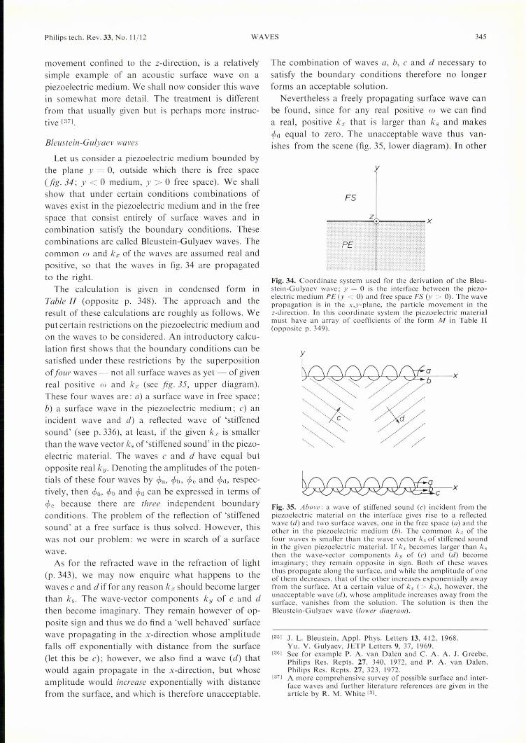
Philips tech. Rev. 33, No. 11/12
movement confined to the z-direction, is a relativelysimple example of an acoustic surface wave on apiezoelectric medium. We shall now consider this wavein somewhat more detail. The treatment is differentfrom that usually given but is perhaps more instruc-tive [371.
Bleustein-Gulyaev waves
Let us consider a piezoelectric medium bounded bythe plane y = 0, outside which there is free space(fig. 34; y < ° medium, y > ° free space). We shallshow that under certain conditions combinations ofwaves exist in the piezoelectric medium and in the freespace that consist entirely of surface waves and incombination satisfy the boundary conditions. Thesecombinations are called B1eustein-Gulyaev waves. Thecommon wand kx of the waves are assumed real andpositive, so that the waves in fig. 34 are propagatedto the right.
The calculation is given in condensed form inTable If (opposite p. 348). The approach and theresult of these calculations are roughly as follows. Weput certain restrictions on the piezoelectric medium andon the waves to be considered. An introductory calcu-lation first shows that the boundary conditions can besatisfied under these restrictions by the superpositionoî four waves - not all surface waves as yet - of givenreal positive wand kx (see fig. 35, upper diagram).These four waves are: a) a surface wave in free space;b) a surface wave in the piezoelectric medium; c) anincident wave and d) a reflected wave of 'stiffenedsound' (see p. 336), at least, if the given k.x is smallerthan the wave vector ks of'stiffened sound' in the piezo-electric material. The waves c and d have equal butopposite real ky. Denoting the amplitudes of the poten-tials of these four waves by CPa, CPb, CPc and CPd, respec-tively, then CPa, CPb and CPd can be expressed in terms ofCPc because there are three independent boundaryconditions. The problem of the reflection of 'stiffenedsound' at a free surface is thus solved. However, thiswas not our problem: we were in search of a surfacewave.
As for the refracted wave in the refraction of light(p. 343), we may now enquire what happens to thewaves c and d if for any reason kx should become largerthan kso The wave-vector components ky of c and dthen become imaginary. They remain however of op-posite sign and thus we do find a 'well behaved' surfacewave propagating in the x-direction whose amplitudefalls off exponentially with distance from the surface(let this be c); however, we also find a wave (d) thatwould again propagate in the x-direction, but whoseamplitude would increase exponentially with distancefrom the surface, and which is therefore unacceptable.
WAVES 345
The combination of waves a, b, c and d necessary tosatisfy the boundary conditions therefore no longerforms an acceptable solution.
Nevertheless a freely propagating surface wave canbe found, since for any real positive w we can finda real, positive kx that is larger than kS and makesCPd equal to zero. The unacceptable wave thus van-ishes from the scene (fig. 35, lower diagram). In other
x
Fig.34. Coordinate system used for the derivation of the Bleu-stein-Gulyaev wave; y = 0 is the interface between the piezo-electric medium PE (y < 0) and free space FS (y > 0). The wavepropagation is in the x,y-plane, the particle movement in thez-direction. In this coordinate system the piezoelectric materialmust have an array of coefficients of the form M in Table 1I(opposite p. 349).
Fig.35. Above: a wave of stiffened sound (c) incident from thepiezoelectric materialon the interface gives rise to a reflectedwave (d) and two surface waves, one in the free space (a) and theother in the piezoelectric medium (b). The common k" of thefour waves is smaller than the wave vector k.; of stiffened soundin the given piezoelectric material. If kx becomes larger than ksthen the wave-vector components ky of (c) and (d) becomeimaginary; they remain opposite in sign. Both of these wavesthus propagate along the surface, and while the amplitude of oneof them decreases, that of the other increases exponentially awayfrom the surface. At a certain value of kx (> ks), however, theunacceptable wave (d), whose amplitude increases away from thesurface, vanishes from the solution. The solution is then theBleustein-Gulyaev wave (lower diagram).
[35J J. L. Bleustein, Appl, Phys. Letters l3, 412, 1968.Yu. V. Gulyaev, JETP Letters 9,37, 1969.
[36J See for example P. A. van Dalen and C. A. A. J. Greebe,Philips Res. Repts. 27, 340, 1972, and P. A. van Dalen,Philips Res. Repts. 27, 323, 1972.
[37J A more cornprehensive survey of possible surface and inter-face waves and further literature references are given in thearticle by R. M. White [3J.

346 c. A. A. J. GREEBE Philips tech. Rev. 33, No. 11/12
words, when we attempt to satisfy the boundaryconditions ~or a given cowith the three waves a, bandc, we find that this is possible with one value of ka; thatis larger than ks, so that c is also a surface wave. Thiscombination of three surface waves is the Bleustein-Gulyaev wave, and the relation found between ka; andw is its dispersion relation.In our description of the Bleustein-Gulyaev wave we
thus allowan incident wave and a reflected wave (realkv) to change into two surface waves (imaginary kv),one decreasing and the other increasing exponentiallyin amplitude with distance from the surface. We thencause the unacceptable increasing wave to vanish bychoosing a suitable value ka;(w) for ka;. We note thatthis approach is of general application to surfacewaves: the Bleustein-Gulyaev wave merely serves hereas an example.We shall now look into one or two details of the
calculation. We impose the following restrictions (seeRl- R4 in Table 11): the piezoelectric material musthave a certain symmetry and a certain orientation (R4);the waves must be 'slow' (R2), must propagate in thex,y-plane (RI) and must involve particle displacementin the piezoelectric medium in the z-direction only (R3).The waves must be slow in the sense that only electro-static effects and no electrodynamic effects arise (seealso p. 336); this means that the electric field can bederived from a potential cp (E = -grad cp).For the waves indicated in Table H as FSL, which
can occur in free space under the restrictions RI and R2,k2 = 0 for all w. The wave variables thus satisfy thetwo-dimensional Laplace equation, for k2 = ka;2 ++ ky2 = -(0a;2 + Oy2) = _\12. These are in factstatic field distributions which can propagate at anarbitrary (but not too high) velocity, provided that theboundary conditions at the surface are satisfied. For ka;real, ky is evidently imaginary: ky = ± jka;. The waveto be used for combination (wavea in list L, Table H)must decrease exponentially with distance from thesurface (i.e. upwards in fig. 34) so that for the given ka;,the ky of the wave must be equal to -jka;. Lines offorce and equipotential surfaces of this Lap/ace waveare given in fig. 36.Restrictions on the symmetry and orientation (R4) of
the piezoelectric medium are imposed in the arraymarked M in Table H, which gives the coefficients bymeans of which the variables Tl, T2, ... Da;, Dy, D; areexpressed in terms of the variables SI, S2, ... Ea;, Ey,Ez. The many zeros imply a high symmetry and asimple orientation; the coefficients indicated by pointsare not relevant to the present discussion. Materialswith a six-fold or rotational axis of symmetry areexamples in which the array of coefficients can take theform M. The restrictions RI, R2 and R3 have already
limited the components of Sand E to be taken intoaccount here to S4, Ss, Ea; and Ey and now because ofthe form of the array the components of Tand Darelimited to T4, Ts, D« and Dy.
As a result of the foregoing, there only remain twodifferential equations for the waves in the piezoelectricmaterial: a mechanical equation of motion and one ofMaxwell's equations. The resultant dispersion relationrepresents two waves - again, Laplace waves (PL),with k2 = 0 and further 'stiffened sound' (PS), with thedispersion relation (DS). This reduction of the possiblewaves to two simple types is of course a consequenceof the simplifications introduced by (M). The Laplacewave to be used for combination (wave b in list L,Table H) must decrease with distance from the surface,i.e. downwards in fig. 34, and thus has ky = jka;. Forthe incident sound wave (c in list L), ky > 0; the re-flected wave (d) has a negative kv. In the list L ofpossible waves, only wave variables are included thatenter into the boundary conditions.The boundary conditions BI, B2, B3 express, firstly,
that the boundary y = 0 is a mechanically free surface.The shear stresses (Ta;y = T6 and Tyz = T4) along thesurface and the tensile stress (Tyy = T2) normal to itare thus zero. Two of the boundary conditions (T2 = 0,T6 = 0) are automatically satisfied in all the wavesconsidered, and therefore only one mechanical bound-ary condition remains (BI): T4 = O. The electricalboundary conditions (B2, B3) stating that cp and Dymust be continuous at the surface, follow becauseat the surface the field must be derivable from a poten-tial and there is no source of D, i.e. no charge. We notethat before the introduetion of the boundary condi-tions, the factor exp j(wt - ka;x - kyy) in each waveplays no part - it cancels out in all equations. How-ever, when various waves are combined, different fac-tors exp (-jkyY) are involved. At the boundary thesefactors again vanish since y = 0 there.
Substitution of the wave variables from list L in theboundary conditions (B) yields, after eliminating CPa andCPb, the relation (A) between cpcand CPd. Therefore wearrive at the two conclusions mentioned earlier:
y
Fig. 36. Lines of force (solid curves) and cross-sections of equi-potentials (dashed) of the Laplace wave which decays exponen-tially for y ~ + 00.

Philips tech. Rev. 33, No. 11/12
I. A wave of 'stiffened sound' incident at a certainangle imposes a kx and thus determines indirectly allthe ky's; since k« is smaller than ks, kye and kyd turn outto be real. Using (A) in Table 11,all the wave variablescan be expressed in terms of epe. The angle of reflectionis equal to the angle of incidence (kyd = - kye).The reflected wave has the same amplitude as the in-cident wave (Iepdl = lepel, because the coefficients ofepe and epd in (A) are the complex conjugates of oneanother).11. From (A) we can produce a pure surface wave,
the Bleustein-Gulyaev wave, because wave d vanishes(epd = 0) for the value of kye given in (K) (Table11); thisvalue of kye is positive imaginary and thus c becomesa 'well behaved' surface wave. Substituting this value ofkye in the identity kx2 + ky2 _ ks2 yields expression(DBG) in Table 11, the dispersion relation for theBleustein-Gulyaev wave. The velocity w/kx is independ-ent of w: the Bleustein-Gulyaev wave is therefore dis-persionless.
Notes on the Bleustein-Gulyaev wave
In the foregoing derivation of the Bleustein-Gulyaevwave it was not necessary - as it was in other prob-lems discussed in this article - to assume that e2/ ecwas much less than unity. This underlines once morethe relative simplicity of the Bleustein-Gulyaev wave.We assumed only that the.wave was 'slow' and the dis-persion relation (DBG) shows that this is always thecase except when e2/ ec» I, a situation that in factnever arises.From (K) it can be seen that the penetration depth
increases as e2/ec decreases and becomes infinite, asmentioned earlier, in the limit e2/ec ~ 0; the surfacewave has then degenerated to a bulk wave. In contrastto this, the penetration depth of a Rayleigh-like wavealways remains of the same order as the wavelengthalong the surface. Bearing in mind that, in practicalapplications, the great attraction of surface waves liesin their small penetration depth, it can be seen that theBleustein-Gulyaev wave bas its limitations; only whene2/ec is approximately unity can it match the Rayleighwave in this respect.The factor eo/(eo + e) in (K) also tends to make Ikycl
small and hence the penetration depth large because eis often much larger than eo in piezoelectric materials.In the above the empty space behaves only as a mediumof permittivity eo with no mechanical effect on thesurface. If the empty space is replaced by anothermedium with a large permittivity but still with nomechanical effect on the surface, then the penetrationdepth can be reduced. For this reason the surface issometimes coated with a thin film of metal (e R:! co).Further analysis shows that the wave a then vanishes
WAVES 347
(epa = 0); there is virtually no penetration in the metalso that the metal filmcan be so thin that its mechanicaleffect is negligible. Strictly speaking, we are then deal-ing with a wave problem in a single bounded medium,the piezoelectric material, but with different electricalboundary conditions.
Amplification of surface waves; the effect of a transversemagnetic field
An acoustic surface wave on a piezoelectric materialis accompanied by an electric field that extends beyondthe surface and propagates there as a Laplace wave.The wave can be excited, detected, directed, amplifiedand its dispersion relation changed by means of thiselectric field. Here we shall only examine the ampli-fication of such waves and we shall show that with atransverse magnetic field the amplification can beenhanced.From the foregoing it is fairly evident how to set
about amplifying a surface wave on a piezoelectricmaterial: a semiconductor is placed against the piezo-electric material and a current is passed through it ofsuch .a value that the drift velocity of the electrons ishigher than the wave velocity. We shall see presentlythat this should work; that it does work was first shownexperimentally by J. H. Collins et al. [6l. Comparedwith the bulk-wave acoustic amplifier (see p. 337) thepresent configuration has the advantage that the piezo-electric material and the semiconductor can be selectedindependently, so that an optimum choice can be made.This is one of the reasons why the surface-wave ampli-fier seems to be a step nearer to practical applicationsthan the bulk-wave amplifier. Nevertheless, there arestill great difficulties associated with the surface-waveamplifier. In the first place, the required drift field isvery high (this point is illustrated in fig. 27); this meansthat it is generally necessary to dissipate undesirablelarge amounts of power unless certain precautions aretaken that present practical difficulties.Secondly there is the problem ofthe electric coupling
between the piezoelectric material and the semi-conductor. In a Rayleigh wave, the surface particlesmove primarily in the y-direction (see fig. 33). Thiswave is therefore very sensitive to mechanical contactwith the surface. To avoid this difficulty it can bearranged, for example, to have a gap between the sur-faces of the piezoelectric material and the semiconduc-tor. This gap, however, must be very small (a smallfraction of the wavelength), for otherwise there will beno electric coupling. The Bleustein-Gulyáev wave, inwhich there is particle movement in the z-directiononly, is better in this respect: it is very little affected bythe presence of a substance such as a liquid (whichattenuates a Rayleigh wave strongly), and a dielectric

348 c. A. A. J. GREEBE Philips tech. Rev. 33, No. 11/12
liquid of high permittivity in the gap results in a strongelectric coupling. This, however, may give rise to newdifficulties, such as corrosion of the surfaces by theliquid.
We shall now indicate briefly how acoustic surfacewaves are amplified and how this effect can be enhancedby a transverse field [38]. In fig. 37a, 1 denotes thesemiconductor and 2 the piezoelectric material. In thesemiconductor the slow wave consists of a Laplacewave (see fig. 36); associated with the field E, there isthe bulk current Jb = aoE. In a Laplace wave therecan be no charge fluctuations in the material since inthe Laplace wave div D = - 13\724> = o. The currentthat flows towards and away from the surface gives,however, an alternating surface charge. In fig. 37a it isassumed that the d.c. drift velocity of the electrons iszero and that the Laplace wave, including the surface-charge pattern, travels to the right at velocity vs. Themaxima of positive and negative surface charge mustassume, with respect to the field pattern, the phases asshown: on the right (front) of the positive chargemaxima, the charge must increase, so the current mustbe directed towards these points. In fig. 37a the fieldand the current are in phase: energy is therefore dis-sipated.If the electron gas as a whole is now made to move
through the semiconductor at a drift velocity VelO, thepattern of alternate surface charges itself represents- quite independently of the alternating field E - ana.c. surface current Js (fig. 37b). A smaller bulk currentwill nowmaintain the same surface charge; or the samealternating field E and bulk current Jb will now giverise to a surface-charge wave of larger amplitude.When VelO is equal to Vs no bulk a.c. current will berequired to maintain a surface-charge wave. (Diffusionand trapping of charge carriers are neglected here.) If,finally, VelO becomes larger than Vs, charge has to beremoved from the front of each positive charge maxi-mum by the bulk a.c. current (fig. 37c). Field and cur-rent now have opposite phase and hence energy issupplied to the wave.Itwill be clear that the operation of the surface-wave
amplifier is rather similar to that of the bulk-waveamplifier. In the surface-wave amplifier, however,advantage can be taken of a transverse magnetic fieldin a way that has no parallel in the case of bulk acousticwaves. We shall attempt to explain this by means ofthe equation
tsk, e2 13 (13 + a;fw) a-ko ,(90)k =-t ec 13+ ai/w (13 + ai/w)2 + (ar/W)2
which is simply (78) in a slightly different form. Thisrelation derived for phenomena in the bulk, is not ofcourse exactly valid in this form for surface waves, but
a very similar relation is valid and we use (90) toindicate qualitatively the effect of a transverse magneticfield [39]. The last factor in (90) is of the formpq/(P2 + q2) and it therefore has values between +tand ---{. The 'best' value, ---{, can always be achieved,for arbitrary values of 13 and ai, by giving ar, via thedrift velocity VelO, a suitable (negative) value. From theother factors in (90) it can be seen that the maximumamplification obtainable in this way could be increasedif ei could be made negative, i.e. if the phase differencebetween J and E could be changed in a certain way. Inthe bulk-wave amplifier there is no way of doing this.In the surface-wave amplifier, however, it can be doneby means of a transverse magnetic field. To make thisclear, fig. 37d shows the extreme case of a magneticfield so large that there is a Hall angle of 90° betweenJ and E. The figure shows that for a travelling Laplace
g2
£
Fig. 37. Operation of the acoustic surface-wave amplifier and theeffect of a transverse magnetic field. I semiconductor, 2 piezo-electric material. In the semiconductor, the field E of the Laplacewave (velocity vs) carries with it a bulk a.c. current JIJ and analternating surface charge. For a given alternating field, theamplitude and phase of the surface-charge wave are dependenton the mean drift velocity VdO of the electrons in the semiconduc-tor (see text). a) VdO = 0; b) 0 < VdO < vs; c) VdO > vs. In case(c) amplification occurs. Js is the surface a.c. current directlyassociated with the movement ofthe surface charges with the elec-tron gas as a whole at velocity VdO. d) When a large magnetic field ispresent E and Jb are at right angles to one another which means,for the travelling Laplace wave, a phase difference of 90° betweenJ and E. Such a phase difference can lead to greater amplification.

Philips tech. Rev. 33, No. 11/12
wave this corresponds to a phase difference of 90° be-tween J and E. It is also clear that smaller phase dif-ferences are introduced by smaller fields and that thesign of the phase difference is determined by thepolarity of the magnetic field.
The effect of a transverse field on the amplificationhas been experimentally confirmed for Rayleigh wavesby J. Wolter [40]. Some particulars concerning thisexperiment are given in fig. 38.
Summary. A survey is given of freely propagating electro-magnetic, elastic and electro-elastic waves, the accent fallingon certain types of wave that have attracted attention in elec-tronies and solid-state physics during the last decade or so. Theseinclude helicon waves, amplifying acoustic waves and electro-acoustic surface waves; several more conventional waves are alsodiscussed by way of introduetion.The dispersion relation and structure of a travelling wave in
an unbounded homogeneous medium follow from the differentialequations (assumed to be linear and homogeneous) for theappropriate variables. By allowing the frequency w or the wavevector k to be complex, the attenuation or amplification of thewave in time or space can be represented.
Starting with Maxwell's equations, electromagnetic waves(light) are discussed, first in free space and then in other non-conducting media, whose particular properties can be formallyexpressed in terms of a permittivity which may be complex andmay be a tensor. In this way double refraction and rotation oftheplane of polarization, as in Faraday rotation, are described.Application of the results to conductors (with a permittivity thatformally includes the conductivity) leads to wave phenomena inmetals such as the skin effect and, for very high conductivitiesand very high magnetic fields, helicon waves. The latter arevirtually unattenuated circularly polarized waves (simplest case)with a very strong dispersion so that, for low frequencies, theirvelocity is extremely low (e.g. 10 cm/s at about 20 Hz).
At the plasma frequency of a conductor, transverse EM waveschange from cut-off waves (k imaginary) into travellingwaves and longitudinal waves of arbitrary wavelength are pos-sible. Examples of other longitudinal EM wave phenomena aredielectric relaxation (w imaginary) and Debye-Hückel screening(k imaginary, to zero).
Of the purely elastic waves, in which only mechanical variablesare involved (displacements, deformations and stresses) onlythose in isotropic media are discussed.
In media where one set of variables is weakly coupled withanother set, the possible waves can often be considered as if theywere two separate coupled waves. The coupling between elasticand EM variables in piezoelectric materials leads to 'near-light'and 'near-sound' (electric transverse waves) and to 'stiffenedsound' (electric longitudinal waves). In piezoelectric semi-conductors the stiffening is complex. This leads, for real co,to an 'amplifying' wave (amplification) if the real part of thecomplex conductivity becomes negative. This can be achievedby means of a constant electric field that gives the electrons acertain drift velocity in the semiconductor (acoustic amplifier).The acoustic attenuation or amplification coefficient is directlyrelated to the acousto-electric field (Weinreich's relation).
In two media with a common boundary the possible wave con-figurations are found by superposition of simple waves with dueregard to the boundary conditions. In this way the reflection andtransmission coefficients can be found for waves at the junctionof two transmission lines or for light or sound incident on aninterface. All component waves must have the same frequencyand the same wave-vector component along the common bound-ary. The laws of reflection and refraction are a direct conse-quence of these requirements. When total reflection occurs oneof the component waves becomes a surface wave.
WAVES 349
Q.
4dB321O~----------~----------~-1-2-3
4
----B=-20kGso
+20
3 2 o -1 -2 -3 -4kV/cm
---- /1B=-O.2o
+0.2
-4 -3 -2 -1 o 2 3 4cm/s_.'1:to
Fig. 38. Effect of a transverse magnetic field on the arnplificationand attenuation of Rayleigh waves, a) experimental b) theoretical,after J. Wol ter [40]. The amplification in dB is plotted in (a) as afunction of the applied drift field Ee, for various values of thetransverse magnetic flux density B; in (b) the amplification isplotted as a function of the drift velocity VdO for various valuesof p,B (J1, = mobility of the electrons in the semiconductor). TheRayleigh waves have a frequency of 50 MHz and are propagatedon the surface of a plate of the piezoelectric material Li~b03.They are amplified or attenuated by the electrons moving in asilicon plate (type N, 150 ncm, 2 mm longx200 [Lm thick) onthat surface. The values of p,B and VdO in (b) are matched (i.e.chosen so that (b) fits (a) as well as possible). The silicon waspressed against the LiNb03 so that the two media were inintimate mechanical contact at one or two places (the Rayleighwave is therefore somewhat attenuated). It was established op-tically that the gap was less than 0.1 [Lm over a length of about0.4 mm. Only over this length was the silicon effective. Thecalculated amplification and attenuation were in reasonableagreement with experiment.
In a freely propagating surface wave, each component wave isa surface wave. As an example, the Bleustein-Gulyaev wave,known since 1968, is described. This is a surface wave by virtueof the piezoelectric property of the medium. This wave is closelyrelated to the reflection of 'stiffened sound' at the surface of apiezoelectric medium. Acoustic surface waves on a piezoelectricmedium can be amplified by a drift current in an adjacent semi-conductor. A transverse magnetic field can enhance this ampli-fication in an interesting way.
[38] A fuller discussion of these and related subjects and furtherreferences are given in: C. A. A. J. Greebe, P. A. van Dalen,T. J. B. Swanenburg and J. Wolter, Electric coupling prop-erties of acoustic and electric surface waves, PhysicsReports lC, 235-268, 1971.
[39] In many problems the description can be made in terms ofeither a complex a or a complex e (see for example eq. 33).Here we use a complex a. In the article ofnote [38] a complexs was used.
[40] J. Wolter, Physics Letters 34A, 87, 1971.

350 Philips tech. Rev. 33, No. 11/12
Recent scientific. publications
These publications are contributed by staff of laboratories and plants which form part ofor co-operate with enterprises of the Philips group of companies, particularly by staff ofthe following research laboratories:
Philips Research Laboratories, Eindhoven, Netherlands EMullard Research Laboratories, RedhilI (Surrey), England MLaboratoires d'Electronique et de Physique Appliquée, 3 avenue Descartes,94450 Limeil-Brévannes, France L
Philips Forschungslaboratorium Aachen GmbH, WeiJ3hausstraJ3e,51 Aachen,Germany A
Philips Forschungslaboratorium Hamburg GmbH, Vogt-Kölln-Straûe 30,2000 Hamburg 54, Germany H
MBLE Laboratoire de Recherches, 2 avenue Van Becelaere, 1170 Brussels(Boitsfort), Belgium B
Philips Laboratories, 345 Scarborough Road, Briarcliff Manor, N.Y. 10510,U.S.A. (by contract with the North American Philips Corp.) N
Reprints of most of these publications will be available in the near future. Requests forreprints should be addressed to the respective laboratories (see the code letter) or to PhilipsResearch Laboratories, Eindhoven, Netherlands.
v. Belevitch: On the realizability of non-rational posi-tive real functions.Int. J. Circuit Theory &Appl. 1, 17-30, 1973(No. I). B
H. J. van den Berg & A. J. Luitingh: Reproducibilityand irreproducibility of etching time in freeze-etchr.expenments.Cytobiologie 7, 101-104, 1973 (No. I). E
I
J. Blbem (Philips Semiconductor Development Labo-ratory, Nijmegen): High chemical vapour depositionrates of epitaxial silicon layers.J. Crystal Growth 18, 70-76, 1973 (No. I).
iP. W. J. M. Boumans: Spektralanalysen. OptischeAtomspektroskopie.Techn, Rdsch. 63, No. 37,49-53 & No. 43, 33-37,1971.
E
K. Hl J. Buschow, A. M. van Diepen & H. W. de Wijn(State University of Utrecht): Evidence for RKKY-type interaction in intermetallics, as derived frommagnetic dilution of GdPdln with Y or Th.Solid State Comm. 12,417-420, 1973 (No. 5). E
M. O. W. van Buul & L. J. van de Polder: Standardsconversion of a TV signal with 625 lines into a video-phone signal with 313 lines.Philips Res. Repts. 28, 377-390, 1973 (No. 4). E
~K. L.' Bye, P. W. Whipps & E. T. Keve: High internalbias fields in TGS (i.-alanine).Ferroelectrics 4, 253-256, 1972/73 (No. 4). M
i ' .F. M;.A. Carpay: Theory of and experiments on alignedlamellar eutectoid transformation.Reactivity of solids, Proc. 7th Int. Symp., BristoI1972,pp. 6~2-622. E
F. M~A. Carpay: Aligned composite materials obtainedby solid state decomposition.J. Crystal Growth 18,-124-128, 1973 (No. 2). E
V. Chalmeton: Neutron radiography.Acta Electronica 16, 73-84, 1973 (No. I). (Also inl'rench.) L
J. W. Chamberlayne & B. Gibson: Magnetic materialsfor integrated cores.IEEE Trans. MAG-8, 759-764, 1972(No. 4). M
T. A. C. M. CIaasen, W. F. G. Mecklenbräuker &J. B. H. Peek: Some remarks on the classification oflimit cycles in digital filters.Philips Res. Repts. 28, 297-305, 1973 (No. 4). E
J. A. Clarke & E. C. Yeadon (Mullard Ltd, Mitcham,Surrey): Measurement of the modulation transferfunction of channel image intensifiers.Acta Electronica 16, 33-41, 1973 (No. I). (Also inl'rench.) M
G. Clément & C. Loty: The use of channel plate elec-tron multipliers in cathode-ray tubes.Acta Electronica 16, 101-111, 1973 (No. I). (Also inFrench.) L
J. Cornet & D. Rossier: Phase diagram and out-of-equilibrium properties of melts in the As-Te system.Mat. Res. Bull. 8, 9-20, 1973 (No. I). L
C. Z. van Doorn: On the magnetic threshold for thealignment of a twisted nematic crystal.Physics Letters 42A, 537-539, 1973 (No. 7). E
H. Dormont: Modèle théorique de système à avalancheconduisant à une étude du bruit.Le bruit de fond des composants actifs semi-conduc-teurs, Collo Int. C.N.R.S. No. 204, Toulouse 1971,pp. 189-192; 1972. L
D. L. Emberson (Mullard Ltd, Mitcham, Surrey) &R. T. Holmshaw: The design and performance of aninverting channel image intensifier.Acta Electronica 16, 23-32, 1973 (No. I). (Also inFrench.) . , M

~IS4 = - jkyuz~u'"=0 ->- Ss =- jk",uz? Uu= 0 other S are
zero
Table II. Derivation of the Bleustcin-Gulyaev wave
RI. Restrietion to waves propagating in the x,y-plane: ()z = 0
~
E", =jk",e/>R2. Restrietion to slow waves: E = - grad e/>->- E,u = jkye/>
Ez =0
Waves in free space
D= lioE
Maxwell's equation:
div D = 0 ->- k2<p= 0t
Dispersion relationk2 = 0
Laplace waves
k2 = 0
D» =jk",lioe/>Du = jkulio<PDz =0
(FSL)
R3. Restrietion to displacementin the z-direction:
Waves in piezoelectric medium
R4. Piezoelectric coefficients:
(M)
Tl 1 0 0 0 0T2 : 0 0 0 0T3 0 0 0 0 t.~-jk,(ro, +'.JT4 0 0 0 c 0 0 o -e 0 Ts = - jk",(cuz + e<p)Ts 0 0 0 0 c o -e 0 0 D", =- jk",(euz - lie/»TG I 0 0 0 0 Du =- jku(euz - ee/»D", Ö 0 0 0 e 0 e 0 0 other Tand D are zero
Dy 0 0 0 e 0 0 0 s 0
1Dz 0 0 0 0
Mech. eq. of motion: em()t211z= ()",Ts+ ()yT4 ~->- ~ c(k2-emW2)lIz + ek2e/>= 0
Maxwell's equation: div D = 0 ~? ek2uz - ek2e/>= 0
Dispersion relation k2 [ (se + e2)k2 - liemW2J = 0 ...--JLaplace waves 'Stiffened sound'
k2 = 0
l{z = 0
Ts = -jkzee/>
D", =jkzlie/>Du ~jkuee/>
W2 e2 c-= (1 +-)-ks2 se em
(DS)with
ee/>u» =-
ee2 se
T4 =-jky(I+-)-c/>se ee2 se
Ts =- jk",(1 + -)- e/>se e
D",=ODu=O
(PL) (PS)
(L)
Waves with real positive wand k", to be used for superposition
a) The Laplace wave b) The Laplace wave c) 'Stiffened sound', d) 'Stiffened sound',in free space in thepiezoelectric incident wave: reflected wave:which decays medium which de-exponentially cays exponentiallyfor y ->- + 00: for y ->--00:
kuil. = -jk", kUb = + jk", kyc = + Vks2_k",2 kyd = -kyc
e/>a e/>b e/>c e/>d
T4b = k",e<pbe2 ec e2 se
T4c = -jkyc(l + -) - e/>c T4d = + jkuc(1 +-) - e/>dse e lie e
Dull. = k",lioe/>a DYb = -k"'lie/>b Duc =0 Dyd = 0
Boundary conditionsT4b + T4c + T4d = 0
DUb =Duae/>b+ <pc+ e/>d= e/>a
:.
(BI)(B2)
(B3)
(A)[
eec ] [ eec ]k", + j(1 +-) (- + I)kyc e/>c+ k",-j(1 + -) (- + l)kyc e/>d= 0• eo e2 eo e2
Solutlous
, ,,1. Reflection of 'stiffened sound' at surface:
k",2 < ks2 ->- kvc real.
<Pd, rpn, <Pb to be calculated from <Pc.
îe/>dl == Ie/>cl·kVd =-kyc.
n. Bleustein-Gulyaev waveeo . e2/lie .
k~~ ~+ ,i+ "I",k. I (KJ
e/>d=Ok",2+ kvc2 = ks2w2 e e2 [ eo e2/ lie ]-=-(1 +-) 1_(__ .__ )2 (DBG)k",2 em lie so + s 1+ e2/lie

Philips tech. Rev. 33, No. 11/12 RECENT SCIENTIFIC PUBLICATIONS 351
F. C. Eversteyn & B. H. Put: Influence of AsH3, PH3,and B2H6 on the growth rate and resistivity of poly-crystalline silicon films deposited from a SiH4-H2mix-ture.J. Electrochem. Soc. 120, 106-110, 1973 (No. I). E
C. Foster, W. H. Kool (both with F.O.M.-Instituutvoor Atoom- en Molecuulfysica, Amsterdam), W. F.van der Weg (Philips Research Labs., Dept. Amster-dam) & H. E. Roosendaal (F.O.M.-Inst. A. & M.,Amsterdam): Random stopping power for protons insilicon.Radiation Effects 16, 139-140, 1972 (No. 1/2).
A. J. Fox: Plane-wave theory for the optical gratingguide.Philips Res. Repts. 28, 306-346, 1973 (No. 4). M
R. G. Gossink: Glasfibers voor optische communicatie.Klei en Keramiek 23, 22-28, 1973. E
J. Graf & R. Polaert: Channel image intensifier tubeswith proximity focussing. Application to low-lightlevel observation.Acta Electronica 16, 11-22, 1973 (No. I). (Also inFrench.) L
D. Hennings: A study of the incorporation of niobiumpentoxide into the perovskite lattice of lead titanate.Reactivity of solids, Proc. 7th Int. Symp., Bristol 1972,pp. 149-159. A
B. Hill & K. P. Schmidt: New page-composer for holo-graphic data storage.Appl. Optics 12, 1193-1198, 1973 (No. 6). H
M. H. H. Höfelt: 'Elastic' constants and wave phenom-ena in bubble lattices.J. appl. Phys. 44, 414-418, 1973 (No. I). E
H. Hörster, E. Kauer, F. Kettel & A. Rabenau (Max-Planck-Institut für Festkörperforschung, Stuttgart):Analyses de diagrammes et de transformations dephase à hautes températures par mesures électriques.Etude des transformations cristallines à haute tempéra-ture au-dessus de 2000 K, ColI. Int. C.N.R.S. No. 205,Odeillo 1971, pp. 39-46; 1972. A
B. B. van Iperen & H. Tjassens: An accurate bridgemethod for impedance measurements of IMPATTdiodes.Microwave J. 15, No. 11, 29-33, 1972. E
G. A. M. Janssen, J. M. Robertson &M. L. Verheijke:Determination of the composition of thin garnet filmsby use of radioactive tracer techniques.Mat. Res. Bull. 8, 59-64, 1973 (No. I). E
W. H. de Jeu, J. van der Veen & W. J. A. Goossens:Dependence of the clearing temperature on alkyl chainlength in nematic homologous series.Solid State Comm. 12,405-407, 1973 (No. 5). E
N. Kaplan, E. Dormann (both with Technische Hoch-schule, Darmstadt), K. H. J. Buschow& D. Lebenbaum(Hebrew University, Jerusalem): Magnetic anisotropyand conduction-electron exchange polarization inferromagnetic (rare-earth)Ah compounds.Phys. Rev. B 7, 40-49, 1973 (No. I). EI
Ili:
F. M. Klaassem.Investigation of low level flicker noisein MOS transistors.Le bruit de fond des composants actifs semi-conduc-teurs, ColI. Int. C.,N.R.S. No. 204, Toulouse 1971,pp. 111-113; 1972. E
W.F. Knippenberg, G. Verspui& G.A. Bootsma: Phasesof silicon carbide.Etude des transformations cristallines à haute tempé-rature au-dessus de 2000 K, ColI. Int. C.N.R.S. No.205, Odeillo 1971, pp. 163-170; 1972. E
R. Koppe: Automatische Abbildung eines planarenGraphen in einen ebenen Streckengraphen.Computing 10, 317-333, 1972 (No. 4). H
J. Krüger & W. Jasmer: Ein neues elektrooptischesVerfahren zur Erzeugung von Mikromustern.Mikroelektronik 5 (KongreI3 INEA, München 1972),202-213, 1973. . H
J.-P. Krumme, G. Bartels & W. Tolksdorf: Mag-netic properties. of liquid-phase epitaxial films ofy3-xGdxFe5-yGay012 for optical memory applications.Phys. Stat. sol. (a) 17, 175~179,1973 (No. I). H
P. K. Larsen & A. B. Voermans: Origin of the con-ductivity minimum and the negative magnetoresistancein n-type sulpho-spinels.J. Phys. Chem. Solids 34, 645-650, 1973 (No. 4). E
P. R. Locher: Nuclear magnetic resonance of 59COonA and B sites in C03S4.Physics Letters 42A, 490, 1973 (No. 7). 1 E
H. H. van Mal: A La'Nis-hydride thermal absorptioncompressor for a hydrogen refrigerator.Chemie-Ing.-Technik 45, 80-83, 1973 (No. 2). . E
J. R. ManselI: A study of an experimental TV pick-uptube incorporating a channel plate. :Acta Electronica 16, 113-122, 1973 (No. I). (Also in
IFrench.) M
J. C. P. Millar, D. Washington & D. L. Lamport:Channel electron multiplier plates in X-ray image inten-sification.Adv. in Electronics & Electron Phys. 33A', 153-165,1972. M
A. Mircea, J. Magarshack & A. Roussel: Etude dubruit basse fréquence des diodes Gunn au GaAs et desa corrélation avec le bruit de modulation de fréquencedes oscillateurs à diode Gunn. ~Le bruit de fond des composants actifs semi-conduc-teurs, ColI. Int. ,C.N.R.S. No. 204, Toulouse 1971,pp.217-223;1972. : L
•D. Muilwijk (Philips' Telecommunicatie Industrie B.V.,Hilversum): Comparison and optimization of multi-plexing and modulation methods for a group of radionetworks. . iPhilips Res. Repts. 28, 347-376, 1973 (No. 4).
A. G. van Nier An operator treatment of modulatedcarriers.Proc. IEEE 61, 131-132, 1973 (No.~I). ! E

.--------c~ ---~----. ~- ~-.-----
352 RECENT SCIENTIFIC PUBLICATIONS Philips tech. Rev. 33, No. 11/12
S. G. Nooteboom & I. H. Slis (Institute for PerceptionResearch, Eindhoven): The phonetic feature of vowellength in Dutch.Language and Speech 15, 301-316, 1972 (No. 4).
I
A. van Oostrom : Field ion microscopy.Acta Electronica 16, 59-71, 1973 (No. I). (Also inFrench.) E
R. A. Ormerod & R. W. A. Gill: Electroforming forelectronics.Trans. Inst. Met. Finish. ?1, 23-26, 1973 (No. I). M
J. A. Pals: Measurements of the surface quantizationin silicon n- and p-type inversion layers at temperaturesabove 25 K.Phys. Rev. B 7, 754-760, 1973 (No. 2). E
R. I. Pedroso & G. A. Domoto (Columbia University,New York): Inward spherical solidification - solutionby the method of strained coordinates.Int. J. Heat & Mass Transfer 16, 1037-1043, 1973(No.5). N
A. Rabenau (Max-Planck-Institut für Festkörper-forschung, Stuttgart) & H. Rau: Über die SystemeTe-TeCl4 und Te-TeBr4. ,z. anorg. allg. Chemie 395,273-279, 1973 (No. 2/3). A
H. Rau & J. F. R. Guedes de Carvalho: Equilibria ofthe reduction ofNiO and CoO with hydrogen measuredwith a palladium membrane.J. chem. Thermodyn. 5, 387-391, 1973 (No. 3). A
W. Rey, R. Bernard (Hopital St. Pierre, Bruxelles) &H. Vainsel (Hop. St. Pierre, Br.): Adaptivité en sur-veillance de l'ECG et détection par ordinateur desarythmies.J. Inform. méd. IRIA, mars 1973, 1, 185-191. B
J. M. Robertson, M. J. G. van Hout, M. M. Janssen&W. T. Stacy: Garnet substrate preparation by homo-epitaxy.J. Crystal Growth 18, 294-296, 1973 (No. 3). E
C. J. M. Rooymans: Growth and applications of singlecrystals of magnetic oxides.Etude des transformations cristallines à haute tempé-rature au-dessus de 2000 K, Collo Int. C.N.R.S. No.205, Odeillo i971, pp. 151-162; 1972. EA. Roussel & A. Mircea: Identification of a bivalentflaw in n-GaAs from noise measurements.Solid State Comm. 12, 39-42, 1973 (No. I).
G. Salmer, J. Pribetich (both with Université desSciences et Techniques de Lille), A. Farrayre & B.Kramer: Theoretical and experimental study of GaAsIMPATT oscillator efficiency.J. appl. Phys. 44, 314-324, 1973 (No. I).J. Schramm & K.Witter: Gas discharges in very smallgaps in relation to electrography.Appl. Phys. 1, 331-337, 1973 (No. 6).L. A. IE. Sluyterman & J. Wijdenes: Benzoylamido-acetonitrile as an inhibitor of papain.Biochim. biophys. Acta 302, 95-101, 1973 (No. I). E
M. J. Sparnaay: Surface analysis with the aid of low-energy electrons. The case of semiconductor surfacescompared with other methods.J. radioanal. Chem. 12, 101-114, 1972 (No. I). E
P. J. Strijkert, R. Loppes (University of Liège) & J. S.Sussenbach: The actual biochemical block in the arg-2mutant of Chlamydomonas reinhardi.Biochem. Genet. 8, 239-248, 1973 (No. 3). E
A. L. Stuijts: Sintering theories and industrial practice.Materials Science Research 6: Sintering and relatedphenomena, editor G. C. Kuczynski, pp. 331-350, 1973.
E
J. L. Teszner (Ecole Normale Supérieure, Paris) &D. Boccon-Gibod: Dependence of Gunn threshold ontransverse magnetic field in ·coplanar epitaxial devices.Phys. Stat. sol. (a) 15, K 11-14, 1973 (No. I). L
A. Thayse & M. Davio: Boolean differential calculusand its application to switching theory.IEEE Trans. C-22, 409-420, 1973 (No. 4). 'IJJ. B. Theeten, L. Dobrzynski (Institut Supérieur d'Elec-tronique du Nord, Lille) & J. L. Domange (E.N.S.C.P.,Paris): Vibrational properties of the adsorbed mono-layer on face-centered cubic crystals.Surface Sci. 34, 145-155, 1973 (No. I). L
J. F. Verwey, J. H. Aalberts & B. J. de Maagt: Driftof the breakdown voltage in highly doped planar junc-tions.Microelectronics and Reliability 12, 51-56, 1973(No. I). EJ. Visser: The gas composition in r.f. sputtering sys-tems and its dependency on the pumping method.Journées de Technologie du Vide, Versailles 1972(Suppl. Le Vide No. 157), pp. 51-66. E
M. T. Vlaardingerbroek & Th. G. van de Roer (Eind-hoven University of Technology): On the theory ofpunch-through diodes.Appl. Phys. Letters 22, 146-148, 1973 (No. 4). E
J. A. Weaver: Optical character recognition.Physics Bull. 24, 277-278, 1973 (May). M
L
J. S. C. Wessels, O. van Alphen-van Waveren &G. Voorn: Isolation and properties of particles con-taining the reaction-center complex of Photosystem 11from spinach chloroplasts.Biochim. biophys. Acta 292, 741-752, 1973 (No. 3). EM. V. Whelan: Resistive MOS-gated diode light sen-sor.Solid-State Electronics 16, 161-171, 1973 (No. 2). E
L
H. W. de Wijn (State University of Utrecht), A. M. vanDiepen & K. H. J. Buschow: Effect of crystal fields onthe magnetic properties of samarium intermetallic com-pounds.Phys. Rev. B 7, 524-533, 1973 (No. I). E
H A. W. Woodhead & G. Eschard: Introduetion (toChannel electron multipliers issue of Acta Electronica).Acta Electronica 16, 8 (in English), 9 (in French), 1973(No. I). M,L
Volume 33, 1973, No. 11/12 Published 5th April 1974pages 309-352