electromagnetic analysis of flux barrier u-shaped
TRANSCRIPT
Electromagnetic Analysis of Flux Barrier U-Shaped Permanent Magnet Vernier Motor
Nima Arish*, Maarten J. Kamper, Rong-Jie Wang
Department of Electrical and Electronic Engineering Stellenbosch University
Stellenbosch, South Africa Email: [email protected]*, [email protected], [email protected]
Abstract—Permanent magnet Vernier machines are well suited for direct-drive industrial applications such as ship propulsion drives, because of their ability to generate high torque at low speeds. In this paper, a flux-barrier tapered-U-shaped permanent magnet Vernier (FBU-PMV) machine topology is proposed. This topology is compared with the spoke-array permanent magnet Vernier (SA-PMV) and the flux-barrier spoke-array permanent magnet (FBSA-PMV) machine topologies. The comparison is done in terms of back-EMF, PM flux, air-gap flux density, synchronous inductance, torque, and power factor, by employing finite element (FE) analysis for the same machine dimensions. It is shown that the proposed FBU-PMV machine topology competes reasonably well with the existing ones even with 25% less PM usage. In addition, the mechanical construction of this new topology also possesses certain advantages.
Keywords— finite element analysis, flux barrier, magnetic orientation, permanent magnet, spoke array, vernier motor.
I. INTRODUCTION The history of the Vernier machine is less than six decades.
The first concept of a permanent magnet Vernier (PMV) machine was introduced 25 years ago [1, 2]. There are many industrial applications where electrical machines with high torque capability at low speeds are required. One of these applications is the ship propulsion drive, which operates at the range of kilowatt to megawatt power range [3, 4]. The PMV-machine is well suited for these applications because it can afford high torque at low speeds due to the “so-called” magnetic gearing effect [5, 6]. Because of this unique feature, the PMV machine is inherently a good candidate for direct-drive applications, which leads to the reduction of maintenance time and cost associated with geared drives [7-9]. Over the years, various types of Vernier machines have been proposed. The first PMV machine was designed with a surface-mounted PM structure [10, 11]. Early PMV machine designs suffer from high leakage flux and low power factor. In recent years, some new Vernier machine topologies have been introduced to alleviate the weakness of this machine. For improving the low power factor, high-temperature superconductor and non-magnetic material have been used to reduce the leakage flux [12-14]. In addition, various types of dual-stator and dual-excitation Vernier machines with spoke-type PM array have been proposed [15, 16]. Although the existence of both internal and external stator windings can increase power factor and torque density, it also brings thermal and manufacturing problems. To tackle this problem, an alternative structure for a dual-excitation
PMV machine, which does not contain an inner stator winding [17], has been proposed. The authors in [18, 19] show that the magnetic orientation has a considerable impact on the performance of the Vernier machine; by changing the magnetic orientation for the same PM volume, the performance such as leakage flux, power factor, torque density and induced voltage of the proposed machines is improved. In [20], by exploiting the flux concentration feature of a Halbach array with a nonmagnetic rotor instead of a simple PM arrangement, the electromagnetic performance of the proposed machine is improved. Also, in [21], by changing the profile of a simple PM array in a five-phase interior Vernier machine to a spoke-type PM array, a design with high torque density and low torque ripple can be realized. In [22, 23], by converting the magnet pole of a consequent pole Vernier machine to a Halbach array, the leakage flux is significantly minimized resulting in better electromagnetic performance. The authors in [24] show the importance of rotor PM configurations and analyze the effect of four different PM configurations by keeping the same geometry of the machine. In [25, 26], it has shown that using flux barriers in the Vernier rotor structure at the ends of the spoke-array-PMs can reduce ripple torque and increase torque density. However, by introducing these flux barriers, the rotor mechanical strength is somewhat compromised.
In this paper, a novel single-side PMV machine with a tapered-U-shaped PM-rotor arrangement is proposed to reduce leakage flux while keeping a reasonable rotor mechanical construction. The performance of the proposed machine is compared with some existing PMV machine topologies in terms of main electromagnetic characteristics such as back-EMF, PM flux, airgap flux density, inductance and torque. All analyses have been conducted with 2-D finite element using ANSYS Maxwell software with identical machine geometry. The remainder of the paper is organized as follows: The configuration and operation of the selected PMV-machine topologies are described in Section II. The performance analyses and comparison are presented in Section III. Relevant conclusions are drawn in Section IV.
II. CONFIGURATION AND OPERATION
The configurations of the conventional spoke array PMV (SA-PMV), flux barrier spoke array PMV (FBSA-PMV) and the proposed flux barrier tapered-U-shaped PMV (FBU-PMV) motor are shown in Fig. 1(a), Fig. 1(b), and Fig. 1(c), respectively. All the motor models have one laminated stator core and one laminated rotor core.
This work was supported by ABB Corporate Research in Sweden and Stellenbosch University in South Africa.

(a)
(b)
(c)
Fig. 1. Vernier motor 2D FEA models of (a) SA-PMV motor, (b) FBSA-PMV motor [27], and (c) FBU-PMV motor.
It is evident that all the motors have interior PM rotors, 4 poles and 12 open slots. Note that the volumes of the PMs of the rotors for SA-PMV and FBSA-PMV models are the same while the FBU-PMV model has 25% less PM material. The key difference of all the models is the arrangement of the PMs and the flux barriers. The proposed FBU-PMV motor is designed based on the SA-PMV motor. The FBU-rotor has three magnet segments per pole magnetized in three directions, whereas the FBSA-rotor and SA-rotor have two magnet segments per pole magnetized in two directions. The cross-sections of the rotor lamination cuts of the different machines can be seen in Fig. 2. All the laminations have 1-mm thin iron bridges that closes the interior magnet slots.
(a)
(b)
(c)
Fig. 2. Cross sections of rotor lamination cuts of (a) SA-PMV motor, (b) FBSA-PMV motor and (c) FBU-PMV motor.
Since the mechanical strength of the rotor is an important consideration, the practicality of the flux barrier rotor lamination of Fig. 2(b) may raise questions. As for the proposed FBU-rotor of Fig. 2(c), the slightly tapered spoke magnets and their placement (shown in Fig. 3) together with the thin iron bridges make the assembled FBU-rotor mechanically very strong. To investigate the effect of the new rotor pole profile of Fig. 3 on the performance of the PMV motor, its performance is compared in this paper with that of the SA- and the FBSA-PMV motors. The specification details of the PMV motors investigated are given in Table I, with the specific dimension details of the proposed FBU-PMV motor also given.

Fig. 3. Details of design parameters of the proposed FBU-PMV motor.
A. Operation
The ability of the Vernier motor to generate high torque at a low speed is due to the magnetic gear effect. By small rotation of the rotor, the magnetic field changes remarkably, as shown in Fig. 4 for the FBU-PMV motor. It demonstrates the difference in the flux distribution at two different rotor positions, namely, at θ = 0° and θ = 4.5°, where the latter is a quarter of the pole pitch. The relation between the winding pole-pairs (p), stator teeth (Zs) and rotor pole-pairs (Zr) in Vernier machines is governed by:
r sp Z Z± = − (1)
The rotor speed, nr, and gear ratio, Gr, of the PMV motor are respectively given by:
1202r
r
fnZ
= (2)
,rr
ZGp
= (3)
where f is the stator frequency. For all the models in Fig. 1, p = 2, Zr = 10 and Zs = 12 resulting in a gear ratio of Gr = 5. Of course, many combinations of p, Zr and Zs can be selected according to (1) – (3), but the combination with a gear ratio of Gr = 5 is chosen in this work to realize a good power factor [9]. From (2), the rotor speeds of the PMV motor models of Fig. 1 are all nr = 400 r/min at a supply stator frequency of f = 66 Hz, as also given in Table I.
III. PERFORMANCE ANALYSIS The electromagnetic performance analyses of all the PMV
motor models for this study include the back-EMF, PM flux, synchronous inductance, torque, cogging torque, power factor and airgap flux density.
TABLE I. SPECIFICATIONS OF PMV MOTORS INVESTIGATED
Value Parameters 400 r/min 66 Hz
Rated speed Frequency
366 mm Outer stator diameter 262 mm Inner stator diameter 259 mm Outer rotor diameter 134 mm Inner rotor diameter 311 mm Stack length 1 mm Airgap 30 Number of coil-turns
FBU-PMV motor details (see Fig. 3) 27 mm Dcr 24 mm Dsc 28 mm Tst 28 mm Ts 30° τs 17 mm db 22 mm Wpm 10 mm dpm1 11 mm dpm2
(a)
(b)
Fig. 4. Flux distribution of the FBU-PMV motor at θ = 0° and θ = 4.5° mechanical rotor positions.

The performance analyses was done by 2D FE analyses using the ANSYS Maxwell software. In the analyses all the PMV motors (specifications are given in Table I) were at the same loading current and frequency.
A. Magnetic Field Analysis
The magnetic flux distributions of the three machine topologies models under open circuit state are shown in Fig. 5. It can be observed that there is excessive leakage flux through the rotor back yoke of the SA-PMV topology. Owing to the presence of flux barriers in the FBSA-PMV topology, the leakage flux can be effectively reduced. In the proposed FBU motor topology the leakage flux reduces considerably and the rotor back yoke forms part of the main flux path due to the unique U-shaped PM arrangement. Fig. 6 depicts the magnetic vector plots of the three machines under full load state, respectively, where the direction of magnetic flux lines in the machine cross sections can be clearly seen. The magnetic flux density distribution of all models under full load conditions are displayed in Fig. 7, where the maximum flux density is less than 2.5 T. According to the B-H curve of silicon steel in Fig. 8, the flux density level in all the three machine cross-sections are within reasonable range and not heavily saturated. Using flux barriers the leakage flux and saturation effect can be effectively mitigated.
In electrical machine design the airgap flux density is one of the most important parameters. Arranging the PMs in a U-shape can increase the average of the air-gap magnetic flux density. Fig. 9 shows the waveform of the airgap flux density of all three PMV motor topologies under no-load conditions. As can be seen, the airgap flux density of the proposed FBU-PMV motor is higher than that of the other two topologies. The RMS values of the airgap flux density of the SA-PMV, FBSA-PMV and FBU-PMV models are 1.05 T, 1.23 T and 1.26 T.
B. PM Flux and Back-EMF
The PM flux and back-EMF are two important electromagnetic parameters of electrical machines, which are obtained when current excitation is zero. These parameters have considerable effect on the performance of the Vernier machine. Since the back-EMF is a derivation of the PM flux, they are related to each other so that by increasing the PM flux, the back-EMF will also increase. The waveforms of the PM flux and back-EMF for all three motor topologies are depicted in Figs. 10 and 11, respectively.
It is evident that the PM flux and back-EMF of the proposed FBU-PMV motor are higher than those of the other two motor topologies. This improvement is attributed to the much-reduced leakage flux in the proposed FBU-PMV topology. The RMS values of the PM flux and peak values of the back-EMF of the SA-PMV, FBSA-PMV and FBU-PMV models are 0.24 Wb, 130 V and 0.34 Wb, 219 V and 0.4 Wb, 239 V, respectively.
(a)
(b)
(c)
Fig. 5. Flux line distribution of (a) SA-PMV motor, (b) FBSA-PMV motor and (c) FBU-PMV motor.

(a)
(b)
(c)
Fig. 6. Magnetic vector plots of (a) SA-PMV motor, (b) FBSA-PMV motor and (c) FBU-PMV motor.
C. Inductance and Power factor
The value of synchronous inductance relates to the number of poles and the magnetic circuit that has an impact on the electromagnetic parameters. Fig. 12 depicts the synchronous inductance of all the PMV motor models. The proposed FBU-PMV has a higher inductance compared to the other models. This difference is due to the magnet shaping that creates varied magnetic leakage circuits. The average of the synchronous inductances of the SA-PMV, FBSA-PMV and FBU-PMV motor models are 3.6 mH, 2.8 mH and 4 mH, respectively.
Low power factor is the biggest drawback of Vernier motors which appears because of many pole pairs and leakage flux. There are several methods for calculating the power factor. By neglecting the stator resistance, the power factor can be calculated by [15]:
12
1sL IPF
ψ
−
= +
(4)
According to (4), the synchronous inductance, current and PM flux linkage play a prominent role in the value of the power factor, so that by reducing the synchronous inductance and increasing the PM flux linkage, the power factor will improve. The values of the power factors at full-load for the SA-PMV, FBSA-PMV and FBU-PMV motor models are 0.63, 0.73 and 0.71, respectively. In fact, the existence of the flux barriers reduces the leakage flux and associated leakage inductance, which in turn improves the power factor.
(a)
(b)
(c)
Fig. 7. Magnetic flux density distribution plots of (a) SA-PMV motor, (b) FBSA-PMV motor and (c) FBU-PMV motor.

Fig. 8. B-H curve of silicon steel used in the study.
Fig. 9. Airgap flux density comparison of the three PMV motor models.
Fig. 10. Phase PM flux linkage comparison of the three PMV motors.
Fig. 11. Phase back-EMF comparison of the three PMV motors.
D. Torque
The interaction between the PM flux of the rotor and the stator teeth at the open circuit state creates cogging torque. The cogging torque is generated periodically and is dependent on the position of the rotor, the number of the rotor poles and the number of the stator slots. A large amount of cogging torque plays an adverse role as it generates noise and vibration. Cogging torque has been depicted for all the PMV motor models in Fig. 13. As can be seen, the FBSA-PMV motor has a lower cogging torque compared to the other models. The cogging torques of the SA-PMV, FBSA-PMV and FBU-PMV motor models are 63 Nm, 35 Nm, and 70 Nm, respectively. The torque of the PMV motor can be expressed using a simplified equation below [5]:
11 0 ( )
2PM
stk ph ph g PM rBT K L N I D B Gω
= + (5)
Fig. 12. Synchronous inductance comparison of the three PMV motors.
Fig. 13. Cogging torque comparison of the three PMV motors.
Fig. 14. Torque comparison of the three PMV motors.
( , ) ( , ) ( )B t F tPM PMθ θ θ= × Λ (6)
,0 1 0 1 1 1B F B FPM PM PM PM= Λ = Λ (7)
where Dg, Lstk, kω1, Nph, BPM, Λ and FPM are respectively the air gap diameter, stack length, fundamental winding factor, number of turns in series per phase, air gap flux density distribution, the air gap permeance function and PMs magneto-motive force (MMF) distribution. The first term of (5) represents the torque component of a typical synchronous machine while the additional torque component relates to the magnetic gearing effect of a Vernier machine. However, there are also other permeance harmonics that are omitted from (5) and can contribute to the ripple torque of the machine. The ripple torque is usually expressed as a percentage of the average torque. A low torque ripple has a significant impact on the performance and longevity of the machine in the long run. Fig. 14 shows the full load torque waveforms of the PMV motors. It is evident that the torque of the proposed FBU-PMV motor model is higher than the other motor models. The average torque and ripple torque of the SA-PMV, FBSA-PMV and FBU-PMV motor models are respectively 403 Nm, 11%, and 603 Nm, 7%, and 663 Nm, 15%. For a better comparison, the electromagnetic characteristics of the three PMV motor models are summarized in Table II.
2.74E+003 2.00E+005 4.00E+005 6.00E+005 7.41E+005H (A_per_meter)
1.14
1.50
2.00
2.50
3.00
3.45B
(tes
la)
0 100 200 300 400 500 600 700 800 900 1000Time[ms]
0
1
2
3
Air
gap
flux
dens
ity[T
]
SA-PMV FBSA-PMV FBU-PMV
50 100 150 200 250Time[ms]
-1
-0.5
0
0.5
1
PM F
lux[
Wb]
Phase-B FBU-PMV Phase-B SA-PMV Phase-B FBSA-PMV
0 50 100 150 200 250Time[ms]
-300
-200
-100
0
100
200
300
Bac
k-E
MF[
V]
Phase-B FBU-PMV Phase-B FBSA-PMV Phase-B SA-PMV
50 100 150 200 250Time[ms]
2.5
3
3.5
4
4.5
Sync
hron
ous-
Indu
ctan
ce[m
H]
10 -3FBU-PMV SA-PMV FBSA-PMV
0 50 100 150 200 250Time[ms]
-40
-20
0
20
40
Cog
ging
Tor
que[
N.m
]
SA-PMV SA-PMV FBU-PMV
50 100 150 200 250Time[ms]
300
400
500
600
700
800
900
Tor
que[
N.m
]FBU-PMV SA-PMV FBSA-PMV
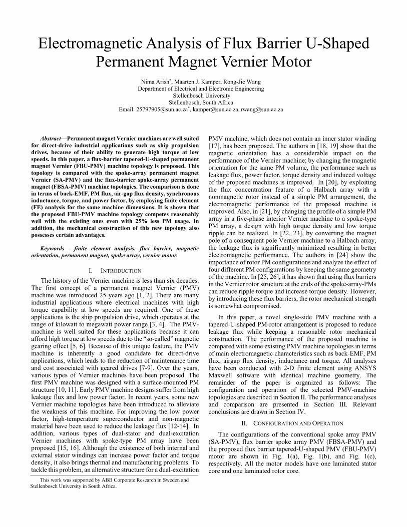
TABLE. II COMPARISON OF ELECTROMAGNETIC CHARACTERISTICS
Parameters FBU-PMV FBSA-PMV SA-PMV PM volume (cm3) 2100 2800 2800 Airgap flux density (T) 1.26 1.23 1.05
PM flux (Wb) 0.4 0.34 0.24 Back EMF (V) 239 219 130 Inductance (mH) 4 2.8 3.6 Power factor 0.71 0.73 0.63 Torque (Nm) 663 603 403 Cogging torque (Nm) 70 35 63
Percentage load torque ripple (%) 15 7 11
IV. CONCLUSION
This paper proposes a new structure of flux barrier tapered-U-shaped PMV motor. The proposed PMV motor have been compared to two existing PMV motor models in terms of airgap flux density, PM flux, back-EMF, synchronous inductance, power factor, cogging torque, average torque and ripple torque. The comparison was done with the PMV motors at the same current loading condition and 25% less PM material in proposed model. From the results the following conclusions are drawn. By changing the structure of the PMs from a spoke array to the proposed U-shape and adding flux barriers, the leakage flux is significantly decreased, leading to a significant increase in PM flux, airgap flux density and back-EMF. The average torque of the proposed FBU-PMV is increased by a significant 9.9% compared to the FB-PMV motor, with a slightly lower power factor. The cogging and load ripple torques, however, are somewhat higher, which must be further investigated. The mechanical strength of the assembled FBU rotor is improved by the proposed tapered-U-shaped pole layout, which is clearly an advantage. With less leakage flux and improved mechanical integrity, the newly proposed FBU rotor offers a significant advantage over the conventional FB rotor.
REFERENCES [1] C. H. Lee, "Vernier Motor and Its Design" IEEE Trans. Power Appar.
Syst., vol. 82, no.66, pp. 343-349,1963. [2] A. Ishizaki, T. Tanaka, K. Takasaki, and S. Nishikata, “Theory and
Optimum Design of PM Vernier Motor,” in 7th International Conference on Electrical Machines and Drives (Conf. Publ. No. 412), 1995, pp. 208-212.
[3] W. Li, T. W. Ching, K. T. Chau and C. H. T. Lee, "A Superconducting Vernier Motor for Electric Ship Propulsion," in IEEE Transactions on Applied Superconductivity, vol. 28, no. 3, pp. 1-6, April 2018, Art no. 5201706, doi: 10.1109/TASC.2017.2787136.
[4] J. Li and K. T. Chau, "A Novel HTS PM Vernier Motor for Direct-Drive Propulsion," in IEEE Transactions on Applied Superconductivity, vol. 21, no. 3, pp. 1175-1179, June 2011, doi: 10.1109/TASC.2010.2085412
[5] P. M. Tlali, R. J. Wang, S. Gerber, C. D. Botha, and M. J. Kamper, “Design and Performance Comparison of Vernier and Conventional PM Synchronous Wind Generators,” IEEE Transactions on Industry Applications, vol. 56, no. 3, pp. 2570-2579, May/Jun 2020.
[6] C. D. Botha, M. J. Kamper, R. J. Wang, and A. Chama, “Analytical Modeling of Surface-Mounted and Consequent-Pole Linear Vernier Hybrid Machines,”IEEE Access, vol. 9, pp. 26251-26259, Feb. 2021.
[7] C. J. J. Labuschagne and M. J. Kamper, "Permanent Magnet Vernier Generator Design for a Small-scale Passive Wind Generator System," in
IEEE International Electric Machines and Drives Conference (IEMDC), Hartford, CT, USA, 2021,
[8] N. Arish and V. Teymoori, “Development of Linear Vernier Hybrid Permanent Magnet Machine for Wave Energy Converter,” Int. J. Eng., 2020.
[9] P. M. Tlali and R. J. Wang, “PM Vernier Machine for Utility Scale Wind Generator Applications: Design and Evaluation,” in Proc. of XXIV International Conference on Electrical Machines (ICEM), pp. 2637-2643, 23-26 Aug. 2020, Gothenburg, Sweden.
[10] A. Toba and T. A. Lipo, “Novel Dual-Excitation Permanent Magnet Vernier Machine,” Conf. Rec. 1999 IEEE Ind. Appl. Conf. Thirty-Forth IAS Annu. Meet. (Cat. No.99CH36370), vol. 4, pp. 2539–2544, 1999.
[11] S. Niu, S. L. Ho, W. N. Fu, and L. L. Wang, “Quantitative Comparison of Novel Vernier Permanent Magnet Machines,” in IEEE Transactions on Magnetics, 2010, vol. 46, no. 6, pp. 2032–2035.
[12] N. Arish, “Electromagnetic Performance Analysis of Linear Vernier Machine with PM and HTS-Bulk,” Phys. C Supercond. its Appl., vol. 579, 2020.
[13] M. Ardestani, N. Arish, and H. Yaghobi, “A New HTS Dual Stator Linear Permanent Magnet Vernier Machine with Halbach Array for Wave Energy Conversion,” Phys. C Supercond. its Appl., 2020.
[14] N. Arish, F. Marignetti, and M. Yazdani-Asrami, “Comparative Study of a New Structure of HTS-Bulk Axial Flux-Switching Machine,” Phys. C Supercond. its Appl., 2021.
[15] D. Li, R. Qu, and T. A. Lipo, “High-Power-Factor Vernier Permanent-Magnet Machines,” in IEEE Transactions on Industry Applications, 2014, vol. 50, no. 6, pp. 3664–3674.
[16] F. Zhao, T. A. Lipo, and B. I. Kwon, “Magnet Flux Focusing Design of Double Stator Permanent Magnet Vernier Machine,” in Proc. Conf. Comput. Electromagn. Fields (COMPUMAG), Budapest, Hungary, Jul. 2013, pp. 1–2.
[17] D. Li, R. Qu, and J. Li, “Development and Experimental Evaluation of a Single-Winding, Dual-Stator, Spoke-Array Vernier Permanent Magnet Machines,” in Proc. IEEE Energy Convers. Congr. Expo. (ECCE), Sep. 2015, pp. 1885–1889.
[18] Q. Wang, X. Qin, and P. D. Pfister, “A Vernier Pseudo- Direct-Drive Permanent-Magnet Machine,” in Proc. of XXIII International Conference on Electrical Machines (ICEM), 2018, pp. 2023-2029.
[19] A. Allahyari, A. Mahmoudi, and S. Kahourzade, “High Power Factor Dual-Rotor Halbach Array Permanent-Magnet Vernier Machine,” in 9th IEEE International Conference on Power Electronics, Drives and Energy Systems (PEDES), 2020, pp. 1-6.
[20] L. Xu, G. Liu, W. Zhao, J. Ji, and X. Fan, “High-Performance Fault Tolerant Halbach Permanent Magnet Vernier Machines for Safety-Critical Applications,” IEEE Trans. Magn., 2016 vo. 52, no. 7, pp. 1-4, July 2016..
[21] G. Liu, M. Chen, W. Zhao, Q. Chen, and W. Zhao, “Design and Analysis of Five-Phase Fault-Tolerant Interior Permanent-Magnet Vernier Machine,” IEEE Trans. Appl. Supercond., 2016.
[22] K. Adnani, S. Shafiei, J. Millimonfared, and J. S. Moghani, “Modified Unipolar Hybrid Permanent Magnet Vernier Machine Using Halbach Array Configuration,” in 10th International Power Electronics, Drive Systems and Technologies Conference (PEDSTC), 2019, pp. 40-43.
[23] W. Tao, H. Zhou, and G. Liu, “A Novel Stator-PM Vernier Fault-Tolerant Machine with Consequent Pole Structure,” 22nd International Conference on Electrical Machines and Systems (ICEMS), 2019, pp. 1-4
[24] G. Liu, Y. Sui, J. Liu, M. Wang, L. Yang, and P. Zheng, “Comparison of Vernier Machines with Different Rotor PM Configurations,” 22nd International Conference on Electrical Machines and Systems (ICEMS), 2019, pp. 1-4.
[25] Y. Pei, Y. Yu, F. Chai and Y. Yu, "Design and Comparative Analysis of a Novel PM Vernier Motor With Trapezoidal Magnets and Flux Barriers for In-wheel Traction Application," 2019 22nd International Conference on Electrical Machines and Systems (ICEMS), 2019, pp. 1-6, doi: 10.1109/ICEMS.2019.8922330.
[26] X. Ren, D. Li, R. Qu, Z. Yu and Y. Gao, "Investigation of Spoke Array Permanent Magnet Vernier Machine With Alternate Flux Bridges," in IEEE Transactions on Energy Conversion, vol. 33, no. 4, pp. 2112-2121, Dec. 2018, doi: 10.1109/TEC.2018.2846259.
[27] W. Liu and T. A. Lipo, "Analysis of Consequent Pole Spoke Type Vernier Permanent Magnet Machine With Alternating Flux Barrier Design," in IEEE Transactions on Industry Applications, vol. 54, no. 6, pp. 5918-5929, Nov.-Dec. 2018, doi: 10.1109/TIA.2018.2856579.