electrochemical methods for electrocatalysis · 2018-01-23 · i – current due to electrochemical...
TRANSCRIPT

ECS
Electrochemical methods for electrocatalysis
Aliaksandr Bandarenka
Physik-Department,Technische Universität München,
James-Franck-Str. 1,D-85748 Garching, Germany1

ECS
Introduction
Potentiostatic
Potentiodynamic
RDE
Impedance
Summary
- Introduction
- Potentiostatic techniques (DC)
- Potentiodynamic techniques (DC)
- Methods involving forced convection
- Electrochemical impedance spectroscopy
- Summary
Outline
2
Outline

ECS
Probing signal 1
Response
ModelingProperties
of the “black box”
Probing signal 2
Probing signal 3
3
System investigation
„Classical“ electrochemical techniques:
Change the electrode potential / apply a bias measure current
Change / apply the current measure the electrode potential
Introduction •
Potentiostatic
Potentiodynamic
RDE
Impedance
Summary
Introduction

ECS
Ele
ctro
de (
an e
lect
ron
cond
ucto
r)
Electrode (an electron conductor)
An electrochemical system
Electrolyte (an ionic conductor)
ē ē
4
Introduction •
Potentiostatic
Potentiodynamic
RDE
Impedance
Summary
- +
Introduction

ECS
4H+
+4ē
2H2
2OH-
-4ē
O2 + 2H+
H2O ↔ H+ + OH-
5
Response of the interface 1
Introduction
Response of the electrolyte
Response of the interface 2
Introduction •
Potentiostatic
Potentiodynamic
RDE
Impedance
Summary

ECS
Ele
ctro
de (
an e
lect
ron
cond
ucto
r)
Electrode (an electron conductor)
A reference electrode
Electrolyte (an ionic conductor)
ē ē
4
Introduction •
Potentiostatic
Potentiodynamic
RDE
Impedance
Summary
- +
Introduction
iV

ECS
Wor
king
Ele
ctro
de
Counter E
lectrode
A reference electrode
Reference Electrode
ē ē
4
Introduction •
Potentiostatic
Potentiodynamic
RDE
Impedance
Summary
- +
Introduction
iV
Potentiostat (invented by Hickling, 1941)

ECS
Working electrodeInterface
ElectrolyteCounter
electrodeInterface
Working electrode
WE CERE
Counter electrode
Modelling of the system in case of a 3-electrode se tup
8
Reference electrode
Introduction
Introduction •
Potentiostatic
Potentiodynamic
RDE
Impedance
Summary
ECS
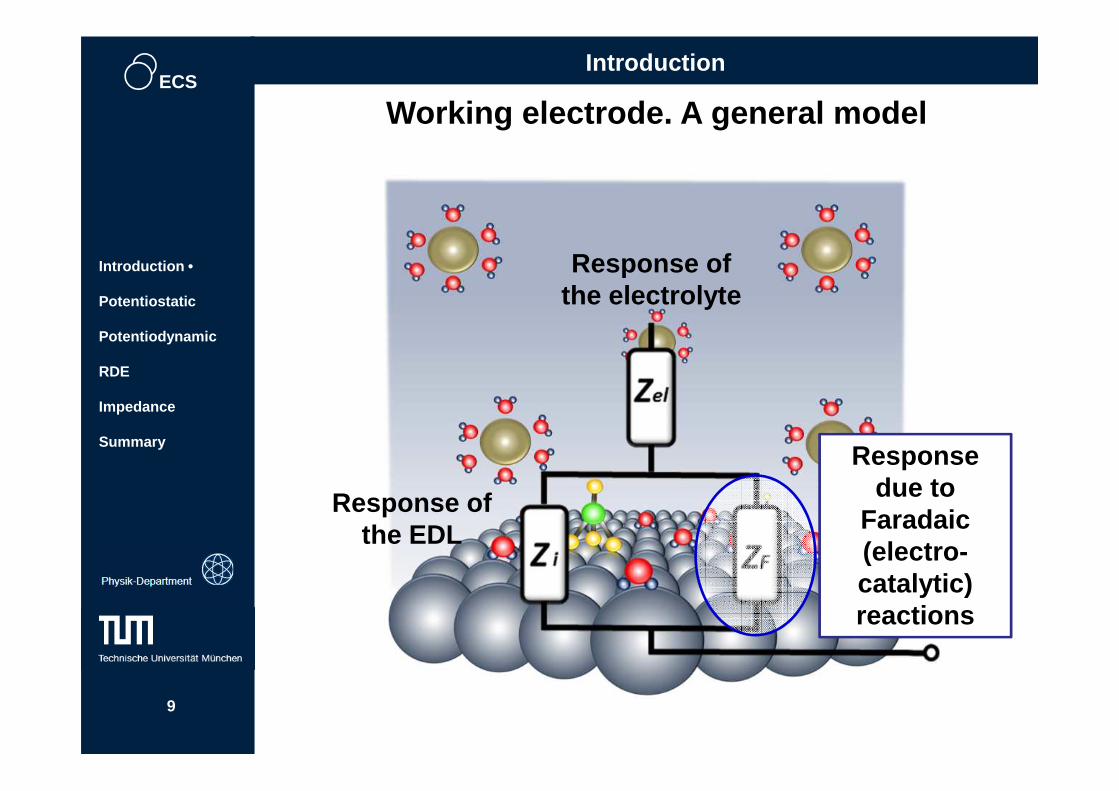
Working electrode. A general model
9
Introduction
Introduction •
Potentiostatic
Potentiodynamic
RDE
Impedance
Summary
Response of the electrolyte
Response of the EDL
Response due to
Faradaic (electro-catalytic) reactions

ECS
Potentiostatic techniquesIntroduction
Potentiostatic •
Potentiodynamic
RDE
Impedance
Summary
10
Potentiostatic techniques (DC)
Stationary electrodes
In these kind of techniques the electrode potential is often kept constant for relatively long time while the current is measured

ECS
0
1.23C
urre
nt /
A
-0.1
0.1
Overpotential ( η)Overpotential ( η)
Electrode potential / V vs RHE
Historically probably the firsttechniques to investigate one of thesimplest electrocatalytic reaction, theHydrogen Evolution Reaction
11
Introduction
Potentiostatic •
Potentiodynamic
RDE
Impedance
Summary
Potentiostatic techniques (DC)

ECS
0 Icapacitive = 0
IFaradaic = const
pote
ntia
l
time
Introduction
Potentiostatic •
Potentiodynamic
RDE
Impedance
Summary
12
Measurement scheme
Potentiostatic techniques (DC)
Chronoamperometry
„Activity“

ECS
time
Pot
entia
lC
urre
nt
Staircase “scan” (slow!)
Current response
time
More complicated measurement scheme
Potential
Cur
rent
(qu
asi-s
tatio
nary
)
Introduction
Potentiostatic •
Potentiodynamic
RDE
Impedance
Summary
13
Potentiostatic techniques (DC)

ECS
Ele
ctro
de p
oten
tial (
MM
S)
Stationary DC current
Introduction
Potentiostatic •
Potentiodynamic
RDE
Impedance
Summary
14
Results for HER obtained by J. Tafel for different metal
electrodes in H 2SO4in 1905
(Zeitschrift fur physikalische Chemie", Vol. 50, pp 641-
712, 1905)
Potentiostatic techniques (DC)

ECSPotentiostatic techniques (DC)
Introduction
Potentiostatic •
Potentiodynamic
RDE
Impedance
Summary
Perovskitesample
Electrochemistry Communications 38 (2014) 142
Oxygen Evolution at RuO 2 and a Perovskite Sample
RuO2 sample
15

ECS
Introduction
Potentiostatic •
Potentiodynamic
RDE
Impedance
Summary
Potentiostatic techniques (DC)
Potential vs RHE
Cur
rent
(qu
asi-s
tatio
nary
)
Possible comparison of different catalysts.Particular case of the oxygen evolution
Catalyst 1
Catalyst 2Some reference current
Reference potentials (overpotentials)
The lower the overpotentialthe better is the catalyst16

ECS
Main advantages and disadvantages
Potentiostatic techniques (DC)
Introduction
Potentiostatic •
Potentiodynamic
RDE
Impedance
Summary
17
Advantages:
Probably the most straightforward techniques insense of the response interpretation, which isimportant for the comparison of different catalysts
Disadvantages:
Do not distinguish different Faradaic processes,which occur simultaneously
Relatively slow, rather stationary systems arerequired
A lot of a priori known information should be takeninto account: e.g. oxide growth on the surface of ametal

ECS
Potentiodynamic techniques
Introduction
Potentiostatic
Potentiodynamic •
RDE
Impedance
Summary
Potentiodynamic techniques (DC)
Stationary electrodes
18
In these kind of techniques the electrode potential is constantly changed while the current is measured

ECSPotentiodynamic techniques (DC)
Introduction
Potentiostatic
Potentiodynamic •
RDE
Impedance
Summary
19
(Cyclic) voltammetry
The most widely used technique for acquiringqualitative and quantitative information aboutelectrochemical (electrocatalytic) reactions
Provides information on redox processes, i.e.interfacial electron transfer including adsorptionprocesses
Gives a quick overview on electrode potentialswhere electrochemical processes take place

ECSPotentiodynamic techniques (DC)
Ele
ctro
de p
oten
tial
Time
Einitial
EMAX
EMIN
Efinal
Cyclic voltammetry. Measurement scheme
- Sweep direction- Sweep rate
Introduction
Potentiostatic
Potentiodynamic •
RDE
Impedance
Summary
20

ECS
Cyclic voltammetry. Measurement schemePt(111) in 0.1M HClO4, Ar-saturated
Introduction
Potentiostatic
Potentiodynamic •
RDE
Impedance
Summary
21
Potentiodynamic techniques (DC)

ECS
Pt(111) in 0.1M HClO 4, Ar-saturated
Cyclic voltammogram
j = F(E)
Potentiodynamic techniques (DC)
Introduction
Potentiostatic
Potentiodynamic •
RDE
Impedance
Summary
22
H-UPD OHads
„EDL-region“

ECS
A voltammogram of CO -monolayer oxidation
0.1M HClO4
Potentiodynamic techniques (DC)
Introduction
Potentiostatic
Potentiodynamic •
RDE
Impedance
Summary
CO-monolayer adsorption
CO-monolayer oxidation
OHads
23

ECS
Voltammograms of CO -monolayer oxidation
Potentiodynamic techniques (DC)
Introduction
Potentiostatic
Potentiodynamic •
RDE
Impedance
Summary
More active surfaces
ACS Catalysis 7 (2017) 435524
Scan rate = 50 mV/s

ECS
Main advantages and disadvantages
25
Advantages:
Non-stationary electrocatalytic systems can beinvestigated
Disadvantages:
Does not distinguish different Faradaic processes,which occur simultaneously
Relatively fast and robust technique
Introduction
Potentiostatic
Potentiodynamic •
RDE
Impedance
Summary
Potentiodynamic techniques (DC)
Often difficult to separate Faradaic and the doublelayer currents

ECS
Methods involving forced convection
Introduction
Potentiostatic
Potentiodynamic
RDE •
Impedance
Summary
Forced Convection
26

ECS
There are three typical modes of ion transport in ionic conductors
Diffusion - Movement of a speciesunder the influence of a gradient ofchemical potential (practically, aconcentration gradient).
Migration - charged particles move toequalize potential gradients in theelectrolyte.
Convection - material is moved by anexternal force such as flow, or rotationof the electrode.
Electrode
Electrolyte
Electrode
27
Introduction
Potentiostatic
Potentiodynamic
RDE •
Impedance
Summary
Forced Convection

ECSForced Convection
Introduction
Potentiostatic
Potentiodynamic
RDE •
Impedance
Summary
Mass transfer rates are larger than just by diffusionalone, therefore the relative contribution of masstransfer to electron transfer kinetics is relatively small
Rather quick steady-state can be reached; the double-layer charging can be excluded at steady-state
Why hydrodynamic methods?
Rotating disk electrode
One of few convectiveelectrode systems for whichthe hydrodynamic equationsand the convective-diffusionproblem have been solvedanalytically
28
Disk electrodes
Insulating parts

ECS
Why hydrodynamic methods?Forced Convection
Introduction
Potentiostatic
Potentiodynamic
RDE •
Impedance
Summary
29

ECS
Electrode
Electrolyte
Rotating disk electrodes
Forced Convection
Introduction
Potentiostatic
Potentiodynamic
RDE •
Impedance
Summary
30
Potentiostatic experiments
Potentiodynamic experiments Examples:
Oxygen reductionHydrogen oxidation
Oxygen evolutionHydrogen evolution

ECS
Phys. Chem. Chem. Phys., 2013, 15, 12998
Rotating disk electrodes
Forced Convection
Introduction
Potentiostatic
Potentiodynamic
RDE •
Impedance
Summary
j/ m
A c
m-2
Ar-saturated HClO 4
O2-saturated HClO 4
Oxygen reduction “signature”
jlim
31

ECS
Rotating disk electrodes
Forced Convection
Introduction
Potentiostatic
Potentiodynamic
RDE •
Impedance
Summary
jlim = BSelectrode C0ω1/2
1j
=1jkinetic
1jlim
+
32

ECS
Rotating disk electrodes. O 2 reduction
Chemical Science 8 (2017) 2283
Forced Convection
Introduction
Potentiostatic
Potentiodynamic
RDE •
Impedance
Summary
Often important for fuel cell research reference point
33

ECS
Chemical Science 8 (2017) 2283
Rotating disk electrodes. O2 reduction activity ranking
Forced Convection
Introduction
Potentiostatic
Potentiodynamic
RDE •
Impedance
Summary
34

ECSForced Convection
Introduction
Potentiostatic
Potentiodynamic
RDE •
Impedance
Summary
Main advantages and disadvantages
Advantage:
Disadvantages:
Fast. Powerful tool to investigate kinetics ofelectrochemical reactions and test catalyticactivities when mass transport plays an importantrole
Acquisition of the integral response. Difficult todistinguish between different Faradaicconstituents
Problems with fast accumulation of impurities atthe electrode surface during the experiments
35

ECSElectrochemical Impedance Spectroscopy
Electrochemical Impedance Spectroscopy
Introduction
Potentiostatic
Potentiodynamic
RDE
Impedance •
Summary
36

ECS
Basics of EIS: data acquisition
probing signal
E = Ebias+ Eacsin(ωit)
at different ac frequencies ωi
Electrochemical system
response
I = I0+Iacsin(ωit+θ)
The “output” is:
1. Modulus of impedance |Z ω|, i.e. the ratio Eac/ Iac
2. A value of the phase shift θω between the probing signal E and the current response I
10mV
WE
RECE
37
Electrochemical Impedance Spectroscopy
Introduction
Potentiostatic
Potentiodynamic
RDE
Impedance •
Summary

ECS
Typical impedance spectra
ImZ =|Z|sin( θ) ReZ = |Z|cos( θ)38
Electrochemical Impedance Spectroscopy
Introduction
Potentiostatic
Potentiodynamic
RDE
Impedance •
Summary

ECS
i
E
i
E
a resistor an electrochemical system
„ Linear“
The amplitude of the ac probing signal in EISexperiments should be small in order to consider oursystem (quasi) linear.
Depending on the system, the amplitude of 1-10 mV isacceptably small
Linearity ( determines probing signal amplitude)
39
Introduction
Potentiostatic
Potentiodynamic
RDE
Impedance •
Summary
Electrochemical Impedance Spectroscopy

ECS
Quasi-stationarity
time
Complications:
≠ ≠ ≠
Possible solution is to minimize the time for the me asurements
40
Electrochemical Impedance Spectroscopy
Introduction
Potentiostatic
Potentiodynamic
RDE
Impedance •
Summary

ECS
Dolin-Erschler-Randles approximation (1940-1947)
Electrolyte
Electrochemical reactions
The double layer
Data analysis
41
Electrochemical Impedance Spectroscopy
Introduction
Potentiostatic
Potentiodynamic
RDE
Impedance •
Summary

ECS
Rel
Rct
RelRct
Cdl
CdlRct
Rct Cdl CdlRct
qM – excess surface charge density on the metal; f(E, v i….)
i – current due to electrochemical reaction f(E, Cs, vi….)
ρ – specific resistance of the electrolyte
l – distance between electrodes
sel – electrode surface area
g – empirical constant depending on the cell geometry, positions of the electrodes etc.
Equivalent electric circuit is a schematic representation of equations describing the
electrochemical system
42
Electrochemical Impedance Spectroscopy
Introduction
Potentiostatic
Potentiodynamic
RDE
Impedance •
Summary

ECS
Solving the inverse problem: Randles circuit
Rel=10ΩRct=100Ω
Cdl=20µF
Rel=10Ω
Rct=100Ω
Cdl= (ωRct)-1
EIS spectrum
n- number of electrons; F = 96485 C/mol; Ci –surface concentrations of electroactive species, ki- het. react. rate constants; Fi(θ)- some functions of the surface coverage (e.g. θ or 1- θ in case of Langmuir adsorption isotherm)
43
Electrochemical Impedance Spectroscopy
Introduction
Potentiostatic
Potentiodynamic
RDE
Impedance •
Summary
ECS
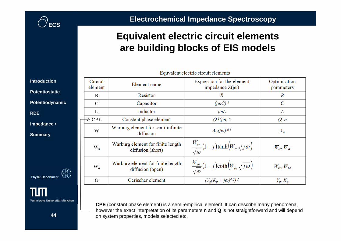
Equivalent electric circuit elements are building blocks of EIS models
CPE (constant phase element) is a semi-empirical element. It can describe many phenomena, however the exact interpretation of its parameters n and Q is not straightforward and will depend on system properties, models selected etc.44
Electrochemical Impedance Spectroscopy
Introduction
Potentiostatic
Potentiodynamic
RDE
Impedance •
Summary

ECS
- Bad news about physical impedance models:
- However the good news are:
ZW
1. It is quite difficult to derive analytical equations for t he physicalEIS models.
2. Many of the parameters in these equations are complexfunctions of the electrode potential, e.g.
kf = k0exp[-αnF(E-E0)/RT]
kb = k0exp[(1-α)nF(E-E0)/RT]
Surface concentrations CO and CR are normallynot equal to the respective bulk concentrationscO and cR. Both CO and CR are complex functionsof the electrode potential
1. For many of typical electrochemical reactions the analyt icalequations for the Faradaic impedance are known (someone els edid this work for us). We only need to assemble the model(equivalent circuit) from the known components using somerelatively simple rules.
2. There are many ways how to simplify the EIS analysis to extr actvaluable physico-chemical parameters.
45
Electrochemical Impedance Spectroscopy
Introduction
Potentiostatic
Potentiodynamic
RDE
Impedance •
Summary

ECS
Picture from the past: “graphical analysis”
- Model postulation, e.g.
- Model verification: just semi-quantitative or visual inspection!46
Electrochemical Impedance Spectroscopy
Introduction
Potentiostatic
Potentiodynamic
RDE
Impedance •
Summary

ECS
The first software for the impedance data fitting using CNLS (1986): a new era of EIS
By James R. MacDonald
Software: LEVM
By Bernard A. Boukamp
Software: EQUIVCRT
Solid State lonics, 18-19 (1986) 136
Solid State Ionics, 24(1) (1987) 61
- Powerful algorithms for the check of data quality- Careful and more objective model verification- More accurate estimation of parameters of the model s
Optimisation algorithm: Levenberg–Marquardt (iterat ive)
47
Electrochemical Impedance Spectroscopy
Introduction
Potentiostatic
Potentiodynamic
RDE
Impedance •
Summary

ECS
Accurate analysis of EIS data is the key
48
Electrochemical Impedance Spectroscopy
Introduction
Potentiostatic
Potentiodynamic
RDE
Impedance •
Summary

ECS
Zi = C′DL−1(jω)−φ,
where C′DL is the parameter, which is proportional to the double layer capacitance,φ ≤ 1 is the CPE-exponent, which is directly related to the
Revealing phase transitions in adsorbate layers
49
Electrochemical Impedance Spectroscopy
Introduction
Potentiostatic
Potentiodynamic
RDE
Impedance •
Summary

ECS
1/3ML OH* with H 2O
1/4ML O*
1/3ML O*
O2-free 0.1M HClO 4
O2-sat 0.1M HClO 4
Langmuir 2011, 27(5), 2058
Revealing phase transitions in adsorbate layers
50
Electrochemical Impedance Spectroscopy
Introduction
Potentiostatic
Potentiodynamic
RDE
Impedance •
Summary

ECS
Comparison between techniques Each technique provides information about only one or several aspects of interfacial processes
Techniques
Voltammetries, static
electrodes
Voltammetries, rotating disc
(ring) electrodes
Impedance spectroscopy
Target aspects Advantages Disadvantages
Averaged information about electrochemical processes at the
interface
Averaged information about electrochemical reactions under
controllable mass transport of
electroactive species
Information about different
constituents of simultaneously
running electrochemical
processes. Averaged for the electrode surface
Fast. Creates first understanding of the
system under investigation.
Investigation of non-stationary systems
Acquisition of the integral response.
Does not “distinguish”
contributions from different processes
Fast. Powerful tool to investigate kinetics of
electrochemical reactions, test
catalytic activities and detect reaction intermediates
Acquisition of the integral response.
Problems with accumulation of impurities at the
electrode surface during the experiments
Powerful tool to reveal physical models of the
interface. Separates contributions from different processes
which occur simultaneously
Relatively slow. Frequent ambiguity
in the model selection: one should
use a priori knowledge or
additional information from other techniques
51

ECS
Where are the most active electrocatalytic centers?
52

ECS
Paul Sabatier(1854-1941)
The interactions between the catalyst and thereaction intermediates should be just right.
The catalyst surface should not bind themneither too strong nor too weak.
The Sabatier principle ( a qualitative concept) (1911)
53
Imagination of a catalyst surface?

ECS
“Most finely divided catalysts musthave structures of great complexity.<…..> In general, we should look uponthe surface as consisting of acheckerboard.” (1922)
Irving Langmuir (1881 –1957)
The catalyst surface is not uniform?
54

ECS
Hugh Stott Taylor(1890-1974)
The concept of active sites
“A catalyzed chemical reaction is e.g. notcatalyzed over the entire solid surface ofthe catalyst but only at certain ‘activesites’ or centers” (1925)
55
Namely the active sites at the surface should bind the intermediates “just right”

ECS
Key initial procedures in (heterogeneous) electro-catalysis
Identification of the nature of the most
active sites
? ?
?
Optimization of the electronic (adsorption)
properties of those active sites
56
Maximisation of the density of those sites
at the surface

ECS
57
A big problem in heterogeneous catalysis: thenature of active sites is known only for fewreactions and only few types of materials
I. Chorkendorff, J. W. Niemantsverdriet, Concepts of Modern Catalysis and Kinetics

ECS
Identification of active sites using EC -STM?
58 J. Pfisterer, Y. Liang, O. Schneider, A.S. Bandarenka // Nature 549 (2017) 74

ECS
Identification of active sites using electrochemical STM?
Oxygen reduction reaction at a Pt(111) terrace
59J. Pfisterer, Y. Liang, O. Schneider, A.S. Bandarenka // Nature 549 (2017) 74
pH=1

ECS
60
J. Pfisterer, Y. Liang, O. Schneider, A.S. Bandarenka // Nature 549 (2017) 74
pH=1
Hydrogen evolution at a Pt(111) terrace

ECS
61
J. Pfisterer, Y. Liang, O. Schneider, A.S. Bandarenka // Nature 549 (2017) 74
pH=1
Oxygen reduction at a Pt(111)

ECS
62J. Pfisterer, Y. Liang, O. Schneider, A.S. Bandarenka // Nature 549 (2017) 74
pH=1
Hydrogen evolution at Au(111)/Pd (ML)

ECS
„ON“Hydrogen evolution at Au(111)/Pt(ML)
Y. Liang, C. Csoklich, A.S. Bandarenka // in preparation
„OFF“
Pt
Au
Au
Pt
Au
Au
63

ECS
64
Oxygen electroreduction at Pt(111) in 0.1M LiOH
ORR ON
ORR OFF
ORR ON
ORR OFF
Y. Liang, D. McLaughlin, A.S. Bandarenka // in preparation

ECS
Oxygen electroreduction at Pt(111) in 0.1M LiOH
OFF
ON
Y. Liang, D. McLaughlin, A.S. Bandarenka // in preparation
65

ECS
Oxygen electroreduction at Pt(111) in 0.1M LiOH
Y. Liang, D. McLaughlin, A.S. Bandarenka // in preparation
66

ECS
Oxygen electroreduction at Pt(111) in 0.1M KOH
Y. Liang, D. McLaughlin, A.S. Bandarenka // in preparation
ORR ON
ORR ON
ORR OFF
67

ECS
Oxygen electroreduction at Pt(111) in 0.1M KOH
Y. Liang, D. McLaughlin, A.S. Bandarenka // in preparation68

ECS
Y. Liang, D. McLaughlin, A.S. Bandarenka // in preparation
Oxygen electroreduction at Pt(111) in 0.1M CsOH
69
Compare with:

ECS
Forward vs inverse problems
The inverse problem consists of using the actual result of somemeasurements to infer the model and get the parameters thatcharacterize the system.
While the forward problem has (in deterministic physics) aunique solution, the inverse problem does not
Learn more : Albert Tarantola. Inverse problem theory and methods for model parameter estimation. Siam 2005, ISBN 0-89871-572-5
Forward problem:
We know the model We calculate the response
We measure the response
Inverse problem: …
y = a0+a1x+a2x2+a3x3+…???
???
70
Summary
Introduction
Potentiostatic
Potentiodynamic
RDE
Impedance
Summary •

ECS
Thank you for your attention!
71