electricity networks asset strategy and performance functional scope - functional... · electricity...
TRANSCRIPT
ELECTRICITY NETWORKS
Asset Strategy and Performance
Functional Scope
Functional Scope Created 05.04.2016 By James Osborne
Ex: 2140
Project RO Dene Ward Ex: 4747
Project Title
REFCLS_CDN
Network No. and F/C 5102399
Last Update 06.01.2017 By James Osborne Version 1.2
Related Scopes
Project Engineer James Osborne
System Planning Engineer
Protection and Control Engineer James Osborne
Plant and Stations Engineer
Asset Strategy Engineer
Required Quote Date
System Requirement Date 2018
Revision History:
Version Date Changes Responsible Officer
1.0 05.04.2016 Original J. Osborne
1.1 24.06.2016 Updated Vee Connected VT, SEL451 Relay J. Osborne
1.2 06.01.2017 Updated based on GSB and WND installations J. Osborne
REFCL.01 - Functional design scope (CDN).docx Page 1 of 22
ELECTRICITY NETWORKS
Asset Strategy and Performance
Functional Scope
1 Project overview This project scope covers the migration of the Camperdown zone substation (CDN) system to a resonant earthed network. Migration to a resonant network requires the installation and operation of a ground fault neutraliser (GFN). This changes the electrical operating characteristics of a zone substation and its distribution network as follows:
• full voltage displacement occurs on the system for operation of the GFN;
• this significantly stresses equipment on the system and may lead to failure;
• this equipment has been identified and included in this scope for replacement as part of the GFN installation; and
• other limitations will dictate part of the operational protocols that will be developed by Electricity Networks.
The GFN provides potential benefits to single-phase-to-ground faults on the 22kV three phase system. It provides no benefit on the following:
• the 12.7kV Single Wire Return System (SWER);
• the 66kV sub-transmission system; and
• the low voltage (LV) system.
1.1 Background The Victorian Government has introduced changes to the Bushfire Mitigation Regulations that require distribution businesses with high voltage (HV) overhead assets in high bushfire consequence areas to meet new performance standards for detection and limiting of arc fault energy. These standards can only be achieved using rapid earth fault current limiters (REFCLs).
A REFCL is a network protection device, normally installed in zone substations that significantly reduce the arc fault energy generated during a phase to ground fault. The reduction in arc fault energy can be so effective that earth fault fire ignition on 22kV three phase networks is almost eliminated.
The Bushfire Mitigation Regulations mandate that REFCLs must provide the required capacity—required capacity means, in the event of a phase-to-ground fault on a polyphase electric line, the ability:
• to reduce the voltage on the faulted conductor in relation to the station earth when measured at the corresponding zone substation for high impedance faults to 250 volts within 2 seconds; and
• to reduce the voltage on the faulted conductor in relation to the station earth when measured at the corresponding zone substation for low impedance faults to:
– 1900 volts within 85 milliseconds; and
– 750 volts within 500 milliseconds; and
– 250 volts within 2 seconds; and
• during diagnostic tests for high impedance faults, to limit:
– fault current to 0.5 amps or less; and
– the thermal energy on the electric line to a maximum I2t value of 0.10;
where:
• high impedance faults means a resistance value in ohms that is equal to twice the nominal phase-to-ground network voltage in volts;
• I2t means a measure of the thermal energy associated with the current flow, where I is the current flow in amps and t is the duration of current flow in seconds;
REFCL.01 - Functional design scope (CDN).docx Page 2 of 22
ELECTRICITY NETWORKS
Asset Strategy and Performance
Functional Scope
• low impedance faults means a resistance value in ohms that is equal to the nominal phase-to-ground network voltage in volts divided by 31.75; and
• polyphase electric line means an electric line comprised of more than one phase of electricity with a nominal voltage between 1 kV and 22 kV.
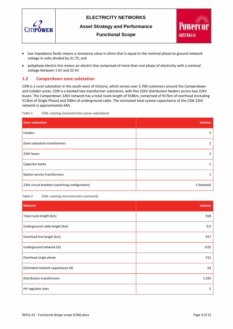
1.2 Camperdown zone substation CDN is a rural substation in the south-west of Victoria, which serves over 5,700 customers around the Camperdown and Cobden areas. CDN is a banked two transformer substation, with five 22kV distribution feeders across two 22kV buses. The Camperdown 22kV network has a total route length of 918km, comprised of 917km of overhead (including 512km of Single Phase) and 500m of underground cable. The estimated total system capacitance of the CDN 22kV network is approximately 64A.
Table 1 CDN: existing characteristics (zone substation)
Zone substation Volume
Feeders 5
Zone substation transformers 2
22kV buses 2
Capacitor banks 1
Station service transformers 1
22kV circuit breakers (switching configuration) 5 (banked)
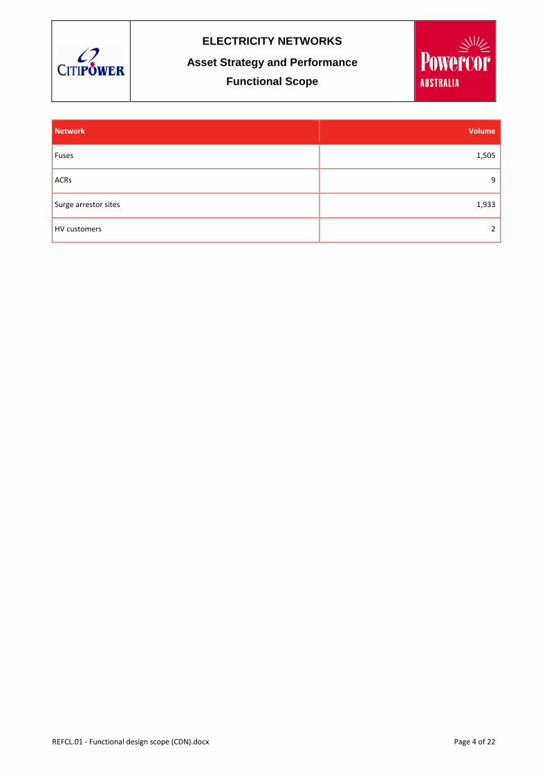
Table 2 CDN: existing characteristics (network)
Network Volume
Total route length (km) 918
Underground cable length (km) 0.5
Overhead line length (km) 917
Underground network (%) 0.05
Overhead single phase 512
Estimated network capacitance (A) 64
Distribution transformers 1,342
HV regulator sites 5
REFCL.01 - Functional design scope (CDN).docx Page 3 of 22
ELECTRICITY NETWORKS
Asset Strategy and Performance
Functional Scope
Network Volume
Fuses 1,505
ACRs 9
Surge arrestor sites 1,933
HV customers 2
REFCL.01 - Functional design scope (CDN).docx Page 4 of 22
ELECTRICITY NETWORKS
Asset Strategy and Performance
Functional Scope
2 ZSS requirements This functional scope sets out the CDN zone substation requirements, including the following:
• establish ASC bunds;
• installation of one (1) Swedish Neutral GFN Arc Suppression Coil;
• modification of the 66/22kV transformer earthing arrangement;
– installation of Neutral Bus System;
– bus CB’s;
– NER terminations;
– ASC Terminations;
– neutral VT Installation;
• upgrade station service supply transformer to (1) new 500kVA kiosk transformer;
• upgrade of the station service supply cabling and installation of new AC distribution board;
• replace ALL substation surge arrestors with new 22kV continuous voltage units for resonant network compatibility and 10hr 24kV TOV capability;
• installation of Station Earth Fault Management control relay (SEL451);
– adoption of existing MEF function;
– neutral Voltage supervision;
– neutral Bus CB Management functions;
– NER Bypass CB Management functions;
– GFN Interface control and management;
• installation of MEF and Neutral Bus Management relay (F35);
– adoption of existing MEF function;
– neutral Voltage supervision;
– neutral Bus CB Management functions;
– NER Bypass CB Management functions;
• install new 22kV feeder CBM relays (5);
• install and Commission one (1) GFN control and one (1) RCC inverter cubicles;
• modification of existing Capacitor Bank;
– remove HV earth from star point;
– install new CB Management relay incorporating overcurrent and earth fault functions;
– Install new station VAR controller;
• install new Elspec Power Quality Meter; and
• replacement of 22kV bus VT (Vee Connected) with a three phase VT.
REFCL.01 - Functional design scope (CDN).docx Page 5 of 22
ELECTRICITY NETWORKS
Asset Strategy and Performance
Functional Scope
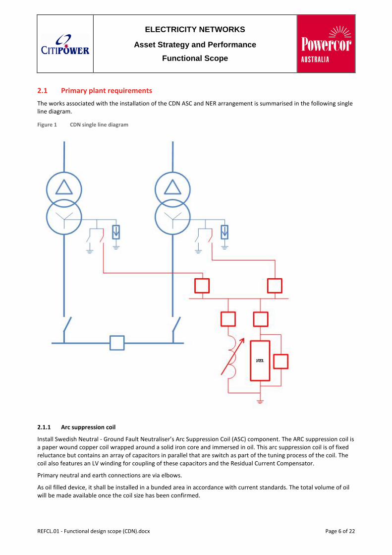
2.1 Primary plant requirements The works associated with the installation of the CDN ASC and NER arrangement is summarised in the following single line diagram.
Figure 1 CDN single line diagram
2.1.1 Arc suppression coil
Install Swedish Neutral - Ground Fault Neutraliser’s Arc Suppression Coil (ASC) component. The ARC suppression coil is a paper wound copper coil wrapped around a solid iron core and immersed in oil. This arc suppression coil is of fixed reluctance but contains an array of capacitors in parallel that are switch as part of the tuning process of the coil. The coil also features an LV winding for coupling of these capacitors and the Residual Current Compensator.
Primary neutral and earth connections are via elbows.
As oil filled device, it shall be installed in a bunded area in accordance with current standards. The total volume of oil will be made available once the coil size has been confirmed.
REFCL.01 - Functional design scope (CDN).docx Page 6 of 22
ELECTRICITY NETWORKS
Asset Strategy and Performance
Functional Scope
The GFN ASC shall be installed in the location of the existing capacitor bank.
• install Ground Fault Neutraliser comprising of 1x 200A ASC and residual current compensation module with maximum available tuning steps onto the provided pad mount within a newly established bunded area;
• the footing of the ASC shall reside on the installed 150mm steel beams fixed to the concrete pad; and
• install cable connections to and from the Neutral System.
2.1.2 Zone substation surge arrestors
The operating principle of the GFN uses a tuned reactance to choke fault current in the event of a single-phase-to-ground fault. As a result, displacement of the line-to-ground voltage occurs in the healthy phases. Whilst line-to-line voltages remain at 22kV, the line-to-ground voltage rises to 22kV, phase-to-ground, on the two healthy phase’s subsequently stressing substation and distribution equipment. In the case of surge diverters, this displacement cannot be tolerated and as such the diverters require replacement.
To accommodate the GFN installation:
• replace all sub-standard zone substation surge arresters with a station class 22kV continuous voltage arrestor
• install station class 19kV surge arresters across the transformer neutrals
2.1.3 Zone substation capacitor bank
The existing No.3 22kV Capacitor Bank is connected in grounded star. The bottom modules of the stack reside on a 22kV insulated structure.
To facilitate GFN installation, the existing cap bank must be removed to allow space for the arc suppression coil, neutral bus module and inverter hut.
A new 22kV, 12MVAr (4x3MVAr steps) capacitor bank is to be installed.
2.1.4 Neutral system arrangement
A new kiosk type ground mounted Neutral Bus system shall be installed with the ASC. The neutral bus system allows for integration of the ASC and NER onto the transformer neutral.
The purpose of this arrangement is to provide a simple switching configuration that offers the following combinations within one kit:
• NER only in service (ASC CB’s open, bus tie closed);
• solid grounding;
• ASC in service (NER CB open) on a common bus; and
• ASC in service (NER CB open) on a split bus (bus tie open).
Neutral Bus
The connection to the Neutral Bus module shall be via elbow connections. Four (4) elbows are required per module for:
• transformer neutral connection;
• ASC connection;
• NER connection; and
• bus tie connection.
REFCL.01 - Functional design scope (CDN).docx Page 7 of 22
ELECTRICITY NETWORKS
Asset Strategy and Performance
Functional Scope
Neutral Voltage Transformer
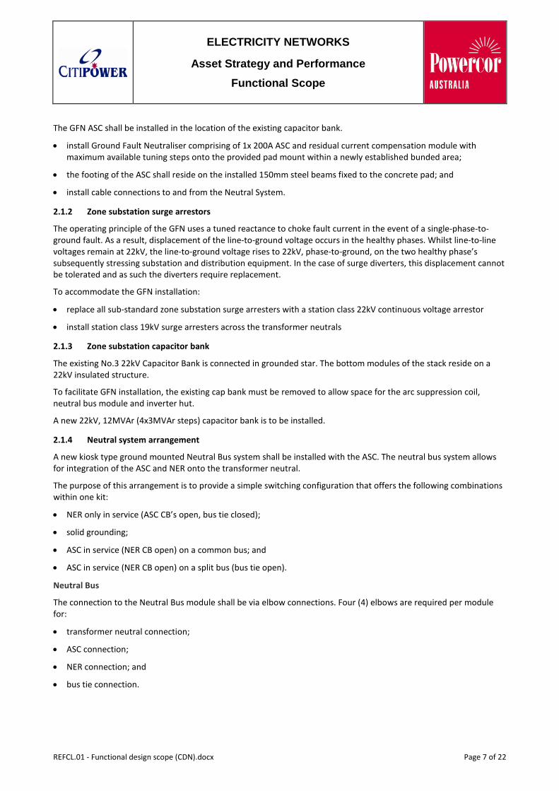
A neutral VT shall be included in the Neutral Bus module. The neutral VT shall be 0.5M 1P at 15VA.
Figure 2 Proposed CDN neutral system single line diagram
2.1.5 Transformer Earthing
The two 66/22kV, 10/12.5 MVA transformers in service at CDN are star/zig-zag connected with the neutral of the zig-zag winding earthed via an 8Ω resistor.
The neutral earthing arrangement shall be modified to incorporate the new NER arrangement (refer SLD) with connection to the ASC. The transformer neutral shall have a new HV insulated single phase cable installed underground from the existing NER isolator (enclosed in a lockable cage) through to HV elbow connections on the Neutral Bus modules.
External earth receptacles are required if any air cable boxes are used.
2.1.6 Neutral surge diverter
As the 66/22kV transformers at CDN are outdoors, neutral surge diverters are to be installed.
Install and connect a Station Class 19kV surge diverter between the transformer neutral bus and the substation earth grid. The surge diverters should be connected as close to the transformer neutrals as possible.
8Ω NER
Trans No.1 ASC
To No.1 TX Neutral Isolator
NER Bypass CB
3 4 VT
To No.2 TX Neutral Isolator
1 2
REFCL.01 - Functional design scope (CDN).docx Page 8 of 22
ELECTRICITY NETWORKS
Asset Strategy and Performance
Functional Scope
2.1.7 22kV Bus VT
Existing 22kV bus VT is a Vee connected VT (phase to phase voltages from VT red and blue windings). Replace existing VT with a VT with the following specification (SAP ID – 381684):
• 3-Phase 5 Limb construction;
• frequency – 50Hz;
• ratio - 22,000/110/110V;
• connection - STAR/STAR/STAR;
• vector group - YNyn0yn0;
• output - 100VA per phase per secondary winding; and
• accuracy class - CLASS 0.5M1P per secondary winding.
2.2 Civil works requirement For neutral system:
• install concrete foundation pad for neutral system module;
• install neutral cable conduit, control cable conduit and provision for solid earth grid connections;
• install neutral cable conduits from transformers to neutral bus;
• install conduits to GFN and NER system; and
• install conduits for secondary circuits.
For ASC:
• install neutral cable conduit, control cable conduits and solid earth grid connections;
• pour concrete foundation;
• install steel beam, 150mm high at a width designed to accommodate the placement of the GFN Arc Suppression coil; and
• install bunding to EPA requirements.
For station service supplies:
• review station service transformer foundations and enclosure for upgrade to 500kVA.
2.3 Secondary works The following outlines the Protection and Control requirements.
All secondary drawings shall be in the wiring schematic format consistent with the existing suite of drawings for the station.
2.3.1 Protection Schemes
Cub 7 – No.1 Capacitor Bank CB Management Relay
• Install new SEL-351S relay to provide Overcurrent, Earth Fault and CB Management function for the No.1 22kV Capacitor Bank
• Retire existing Cap bank overcurrent relay
REFCL.01 - Functional design scope (CDN).docx Page 9 of 22
ELECTRICITY NETWORKS
Asset Strategy and Performance
Functional Scope
• SEL-351s to be connected via dual ethernet point to point links between the two RSG2100 switches located in Cubicle No 17 and Cubicle No 18
Cub 14– Station Earth Fault Management (SEFM) relay
The existing Group – 2650 MEF relay shall be replaced with a modern IED relay to allow flexible control of feeder earth protection and GFN integration. A GE F35 relay shall be installed and configured as the Station Earth Fault management relay. The relay will execute and manage the following functions;
• Master Earth Fault relay for NER in service applications
• Neutral Voltage Supervision
• Neutral CB Management
A GE F35 relay shall be installed and configured as the X MEF and Neutral Bus Management relay. The relay will execute and manage the following functions;
• Master Earth Fault relay for NER/direct earth in service applications
• Neutral Voltage Supervision
• Neutral CB Management
Install a SEL-451 Station Earth Fault Management relay in Cubicle (30) in order to perform the automated control of the GFN’s installed at the substation.
The relay will manage the following functions
• Operating mode selection
• GFN remote controls
• Automate fault detection handling
• Request fault confirmations consistent with operating mode
• Trip faulted zones consistent with operating mode
• Bypass ASC
• Provide local controls and indications
All bypass CB control fuses and MCB’s can be located at the bottom of this cubicle
22 kV Feeder Protections
SEL-351S Feeder Protection Configuration :
• Replace existing feeder SEL-351S relays with new SEL-351S relays with dual Ethernet and 61850 capability.
• Relays shall be reconfigured to provide external protection trip initiations via IEC61850 GOOSE
– These GOOSE initiations shall drive auto reclose functionality direct to lockout through the internal 79DTL function
22kV Feeder CT contributions are required by the GFN zero sequence bus admittance calculations.
To facilitate the GFN connection, install an extra set of neutral links on feeder link rack to permit the installation of the I0 connection off to the GFN controller
2.3.2 Ground Fault Neutraliser
Control Unit
The GFN control unit is a single cubicle comprising of:
REFCL.01 - Functional design scope (CDN).docx Page 10 of 22
ELECTRICITY NETWORKS
Asset Strategy and Performance
Functional Scope
• GFN Master Control module
• GFN Slave Control Module
• Windows Based PC utilising proprietary NM Term software
• All VT and feeder I0 CT terminations
• All trip link outputs
• RCC Inverter and ASC Interface
• Panel Meters
CDN zone substation will require one (1) of these controllers.
Powercor will request through their specification process that the control unit be constructed within a 600mm wide cubicle. The cubicle will contain an interface controller in the form of a SEL-2440 DPAC control unit in the top 2U of this cabinet. This control unit will be used to interface controls to the Station Earth Fault Management relay.
The location of the GFN cubicle shall be in the vacant cubicle 19 position.
VT Supplies (R,W,B and VN ) are required from the bus into the GFN controller along with Feeder, Bus Tie and Transformer neutral summation (IN) circuits.
Inverter
The Residual Current Compensation technique used by the GFN requires an Inverter to inject current into the ASC via an auxiliary winding. The inverter must be sized to displace the full capacitive current drawn by the system and as a result requires significant power.
The performance specification discussed earlier calls for a 0.5A fault current sensitivity. GFN sensitivity is determined by two main factors;
• System Damping
• Capacitive Dissymmetry
The inverter requirement is also quite large as it must have the power to counter balance the system damping and capacitance when in operation. Inverters of size 320kVA is expected.
The inverters must be installed with appropriate cooling, and shall be housed within an air-conditioned enclosure alongside the two Arc Suppression Coils, as indicated in the proposed general arrangement.
2.3.3 VT supplies
Existing VT supplies from the No.2 Bus VT are required to the GFN control unit. For earth fault detection, an open delta (UN) input is required from the 22kV bus VT at 110V secondary. To achieve this, Swedish Neutral has provided an auxiliary transformer in their GFN control cubicle.
2.3.4 Protection settings
A protection review shall be undertaken by Network Protection and Control of all schemes within CDN zone substation with particular reference to earth fault schemes on the 22kV network.
SEL-351S relays will have configuration changes to introduce;
• Directional SEF functionality
• GOOSE (via GFN) tripping capability
• Auto Reclose integration of GFN initiated trips
• GOOSE message isolation function
REFCL.01 - Functional design scope (CDN).docx Page 11 of 22
ELECTRICITY NETWORKS
Asset Strategy and Performance
Functional Scope
The station REF configuration shall be reviewed for GFN integration.
The station MEF and BUEF schemes shall be reviewed for GFN integration.
An application for backup Voltage Displacement shall be considered.
2.3.5 Protection relay configurations
Powercor Network Protection and Control will make standard relay configuration files available to the Service Provider where appropriate. Given the nature of this project, the service provider must expect that this project will have non-standard requirements.
2.3.6 Metering requirements
Power Quality Meter
The existing ION 7600 Power Quality Meter is to be connected to the new CDN-RSG2100-11 Switch located in Cubicle No.17.
Existing 3G modem is to be retired.
An ELSPEC Power Quality and Data recorder shall be installed in Cubicle 7.
This recorder is capable of recording 16 analogue and 32 digital channels of data at a sampling rate of 1000 samples per cycle. 12 months of data can be captured and stored internally using a patented algorithm.
The ELSPEC shall be installed to capture bus voltage, neutral voltage and bus incomer currents (i.e. transformer and bus tie contribution currents). The purpose of this recorder is to aid with GFN commissioning and long term monitoring.
Cubicle 7 contains the existing ION 7600 Power Quality Meter, use of these CT circuits is suggested for the ELSPEC Power Quality meter.
Connectivity to the ELSPEC meter to be fibre 100BASE-FX Ethernet to a new switch in Cubicle No.18
2.3.7 Control and monitoring requirements
Remote Control and Monitoring of new;
• Modified SEL-351S Feeder Protection Relay Configurations
• X MEF, Neutral Voltage and Neutral System CB Management Relay UR F35
• SEL451 Station Earth Fault Management Relay
• GFN Controller
• ELSPEC Power Quality recorder
• Cap Bank CB Management Relay
Shall be via DNP 3.0 with DNP Maps provided to the SCADA group and produced by the service provider in conjunction with Network Protection and Control.
Powercor SCADA group are responsible for developing a suite of ENMAC control pages in conjunction with the Network Operations group and Network Protection and Control.
2.3.8 Communications Requirements
Cubicle No. 16 – RTU Cubicle
• Install new 3G modem and two firewalls in a cluster arrangement.
• RTU is to be connected below the firewalls on one of the new RSG2100 sublan switches into a 10 BASE FL port.
REFCL.01 - Functional design scope (CDN).docx Page 12 of 22
ELECTRICITY NETWORKS
Asset Strategy and Performance
Functional Scope
Ethernet Connectivity
All communications shall be over 100 BASE-FX (optic fibre) Ethernet back to the zone substation Sub-LAN RSG-2100 Ethernet switches. Preferably, devices maintain duplicated Ethernet connectivity either through an internally “switched” architecture or a preferred and failover arrangement.
Tripping from the GFN to the feeder CB’s will be over IEC 61850 via an interface module built into the GFN control cubicle.
Install a new RuggedCom RSG-2100 (CDN-RSG2100-11) switch at the top of the No.1 Bus Feeder Protection cubicle No.17.
Install a new RuggedCom RSG-2100 (CDN-RSG2100-12) switch at the top of the No.2 Bus Feeder Protection cubicle No.18.
• Install Gigabit backbone connection between CDN-RSG2100-11 and CDN-RSG2100-12
• Install fibre Ethernet links from the 5 off SEL-351S Feeder Protection relays to each Ethernet switch
• Install fibre Ethernet links from the SEL-351S cap bank management relay to each Ethernet switch
• Install fibre connections from GFN Interface controller (SEL-2440)
– All Port 5A connections to CDN-RSG2100-11
– All Port 5B connections to CDN-RSG2100-12
– Ensure relay configurations modified to Port Failover configuration
– Ensure Sub-LAN switch architecture configured to support fail over scenario’s
Engineering Access
Powercor SCADA shall ensure remote engineering access is available to select members of the Network Protection and Control group. Remote access is required to all sub-LAN connected devices including protection relays, data recorders and GFN controller.
Time Stamping
Install new Tekron TCG-01 GPS clock, antenna and ensure that earthing is performed carefully using the standard enclosure. This is to be used for time stamping all equipment. All SNTP capable equipment shall synchronise with the CDN GPS SNTP server.
All non SNTP capable equipment is to be connected to the CDN GPS IRIG-b loop.
2.3.9 415/240 AC Supplies
The existing 50 KVA station service supply transformer is located off 22kV bus.
The sizing of the station service transformer is an inadequate capacity for the RCC inverters used to drive faulted phase voltage to zero via the Arc Suppression Coil.
Install new 500 KVA kiosk type station service transformers in place of the existing transformer (subject to space constraints)
Upgrade existing station AC board, incoming mains and change over schemes such that they are compliant with existing standards.
Install AC supplies for the GFN inverter to meet its specifications.
2.3.10 DC Supplies
The battery capacities shall be verified as being of adequate capacity to supply the station standing load and any CB operations that could occur within a 10 hour period following loss of AC Station Service supplies.
REFCL.01 - Functional design scope (CDN).docx Page 13 of 22
ELECTRICITY NETWORKS
Asset Strategy and Performance
Functional Scope
Documentation must be provided that demonstrates the battery amp-hour rating chosen has been sized for the load and the duty of the load. Calculations and appropriate documentation must be provided to demonstrate compliance with IEEE – 485 “IEEE Recommended Practices for Sizing Lead Acid Batteries for Stationary Applications”.
2.3.11 Station Design
As a minimum the secondary design documentation shall include;
• 22kV Station Schematic Diagram
• Protection, Control, Instrumentation and Alarm data schedules
• Control room layout and elevation of cubicles
• Cubicle Layouts
• Wiring schematics/diagrams for individual protection, control and metering schemes
• DC supply schematics
• Remote control equipment and associated data schedules
• Labelling for cubicles and all slide link terminals
• Manufacturer and interface drawings for the Ground Fault Neutraliser equipment
The latest modular design concepts shall be used as far as practical for this project.
2.3.12 Powercor control centre SCADA works
A new series of Control System Pages shall be created for the GFN interface. Consultation between SCADA, Operations and Network Protection and Control is required to establish these pages.
2.3.13 Fibre Optic Cable
Fibre optic patch leads are required for Zone Substation Sub-LAN Ethernet communications.
These optic fibres shall be of OM1 62.5/125um type.
2.3.14 Radio
No radio communications are required.
2.3.15 Building and Property Considerations
Yard Lighting
Switch yard lighting shall be reviewed to ensure adequate coverage of the ASC, Neutral System.
Fire Suppression
The ASC winding is immersed in oil. A review of its design and the amount of contained oil is required to determine if any fire suppression assets are required.
REFCL.01 - Functional design scope (CDN).docx Page 14 of 22
ELECTRICITY NETWORKS
Asset Strategy and Performance
Functional Scope
3 22 kV distribution feeder requirements
3.1 Surge diverters and insulation limitations The operating principle of the GFN uses a tuned reactance to choke fault current in the event of a single-phase-to-ground fault. As a result, displacement of the line-to-ground voltage occurs in the healthy phases. Whilst line-to-line voltages remain at 22kV, the line-to-ground voltage rises to 22kV, phase-to-ground, on the two healthy phase's subsequently stressing substation and distribution equipment. In the case of surge diverters, this displacement cannot be tolerated and as such the diverters require replacement.
To accommodate the GFN installation, replace approximately 1,818 surge diverters across the 22kV three phase and single phase system.
This covers all feeders ex CDN ZSS as well as surge arrestors beyond inter-station open points shall also be upgraded to permit transfer of loads with the GFN in service.
The replacement diverters should be of 22kV continuous rating with a 10 hour 24kV TOV rating.
CitiPower and Powercor standard surge diverters are the ABB MWK 20 and POLIM D 20 arresters.
These do not meet the overvoltage requirement needed for use with a GFN and therefore the higher rated arresters are required.
These surge diverters will be a new standard, applicable to distribution systems with a GFN installed.
3.2 Distribution transformers Operation of the GFN displaces the neutral voltage of the entire 22kV system from the bus to the outer extremities of the feeders. This is different from an NER arrangement, when displacement is at its highest for a fault on the 22kV bus, and decreases for faults occurring down the feeders.
During GFN commissioning, voltage offset testing will simulate the voltage displacement that will occur for a single-phase-to-ground fault (22kV phase-to-ground).
1. Some distribution transformers may not be in a condition to withstand the overvoltage and will subsequently fail during the voltage offset testing
2. Some distribution transformers may fail following repeated subjection to sustained over-voltages caused post commissioning due to normal operation of the GFN
At this time, experience from network resilience (voltage stress) testing at GSB and WND does not support a proactive replacement of any distribution transformers.
3.3 Line insulators As is the case above for distribution transformers, line insulators are also susceptible to premature failure caused by the repetitive over-voltage stresses.
At this time, experience from the network resilience testing does not support a proactive replacement of any line insulators.
3.4 Line regulators Single phase open-delta-connected Cooper regulators displace the system neutral voltage by regulating line-line voltages on two phases as opposed to three.
Closed-delta independent regulator control schemes tap each regulator independently, a similar displacement to the neutral voltage occurs, as per the open-delta mode.
All regulator works shall be compliant with current CitiPower and Powercor standards for 22kV regulators.
REFCL.01 - Functional design scope (CDN).docx Page 15 of 22
ELECTRICITY NETWORKS
Asset Strategy and Performance
Functional Scope
The CDN distribution network contains five 22kV regulating systems:
Table 3 CDN regulating systems
Feeder Name Manufacturer Phasing Issue
CDN1 Cobden P76 Reg Cooper 3 phase Independent controls
CDN6 Pura Pura P32 Reg Cooper 1 phase None
CDN1 Heytesbery P91 Reg Unknown 3 phase None
CDN4 Skipton Rd P87 Reg Cooper 1 phase None
CDN1 Heyblue P22 Reg Cooper 3 Phase Independent Controls
3.4.1 Cobden P76 regulator
Cobden P76 is a three phase 300A regulator connected in close delta. The existing CL6 control schemes are installed on each phase and as such are controlled separately.
This regulator control scheme shall be upgraded to a CL7 Three Phase control unit such that:
• All units regulate and tap together in a master follower style scheme
• Each tank tap position is monitored and fed back into an out-of-step control circuit
• Out-of-step logic shall lock out automatic control within 90 seconds of detection
• All alarms and controls shall be integrated into SCADA
3.4.2 Pura Pura P32
Pura Pura P32 is installed in an acceptable configuration. A condition assessment is required to satisfy the three minute 22kV TOV requirement.
3.4.3 Heytesbury P91
Heytesbury P91 22kV Regulator is a ground type three phase regulator. As it is a common tank unit, it is in an acceptable confirgation.
3.4.4 Skipton Rd P87
Skipton Rd P87 is installed in an acceptable configuration. A condition assessment is required to satisfy the three minute 22kV TOV requirement.
3.4.5 Heyblue P22
Heyblue P22 Reg is a three phase 300A regulator connected in close delta. The existing CL6 control schemes are installed on each phase and as such are controlled separately.
This regulator control scheme shall be upgraded to a CL7 Three Phase control unit such that:
• All units regulate and tap together in a master follower style scheme
• Each tank tap position is monitored and fed back into an out-of-step control circuit
• Out-of-step logic shall lock out automatic control within 90 seconds of detection
• All alarms and controls shall be integrated into SCADA
REFCL.01 - Functional design scope (CDN).docx Page 16 of 22

ELECTRICITY NETWORKS
Asset Strategy and Performance
Functional Scope
3.5 Admittance balancing The ground fault neutraliser uses a tuned inductance (Petersen Coil / Arc Suppression Coil) matched to the capacitance of the distribution system. The 3 phase 22kV distribution system ex CDN zone substation contains approximately 917km of overhead conductor length (excluding SWER). Of this, 514km (56 per cent) is single phase. Whilst planning philosophies have always attempted to balance the single phase system, inevitably this is difficult to achieve. In order to balance the capacitance of the three phase system such that the ASC can be correctly tuned, balancing substations will be placed at nodes on the system that utilise low voltage capacitors to inject the missing capacitance onto the system.
Note: Balance does not refer to the balancing of load. System balance is required from a capacitance-to-ground perspective and affected by route length and single phase connected distribution equipment.
A reconciliation of all 22kV overhead and underground lines routes shall be conducted to assess the scope of the network balancing requirements.
The following steps shall be outworked prior to GFN installation;
1. Consolidate all “Single Phase” and “unknown” conductor into the “BR”, “RW” or “WB” categories
(i) validate “Single Phase” and “unknown” conductor where required
(ii) spot check the validity of current phasing information
2. Consolidate all single phase transformers on the 22kV system and assign to one of the “BR”, “RW” or “WB” categories
3. Ascertain the construction types for all sections
(i) Indicate whether LV subsidiary exists
4. Consolidate all “1 Phase” and “unknown phase” 22kV cable and assign phase information
5. If single phase circuits are used underground, ascertain the design principles behind the single phase underground sections
(i) Conductor type, two or three core?
(ii) Treatment of the unused core (earthed or phase bonded)—if bonded, to what phase?
The course balance shall look at sections of the system in 'switchable blocks' and for any re-phasing and finite admittance balancing opportunities in order to balance out the single phase route lengths and large single phase spurs where the capacitance is fairly easy to approximate.
A tuneable balancing approach shall then look at the system again in switchable blocks for the application of 3-phase admittance balancing substations.
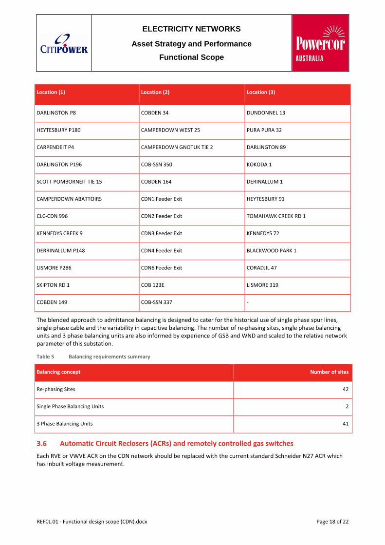
The use of 3-phase admittance balancing substations will provide accurate capacitive balancing in each section. Admittance balancing substations shall be placed at the following locations to enable switching of balanced blocks of the system. These locations are listed below:
Table 4 3-phase balancing unit locations
Location (1) Location (2) Location (3)
LISMORE P113 COBDEN 123 HEYBLUE P22
HEYTESBURY P18 PURRUMBETE SOUTH 2 LWR HEYTESBURY 226
REFCL.01 - Functional design scope (CDN).docx Page 17 of 22
ELECTRICITY NETWORKS
Asset Strategy and Performance
Functional Scope
Location (1) Location (2) Location (3)
DARLINGTON P8 COBDEN 34 DUNDONNEL 13
HEYTESBURY P180 CAMPERDOWN WEST 25 PURA PURA 32
CARPENDEIT P4 CAMPERDOWN GNOTUK TIE 2 DARLINGTON 89
DARLINGTON P196 COB-SSN 350 KOKODA 1
SCOTT POMBORNEIT TIE 15 COBDEN 164 DERINALLUM 1
CAMPERDOWN ABATTOIRS CDN1 Feeder Exit HEYTESBURY 91
CLC-CDN 996 CDN2 Feeder Exit TOMAHAWK CREEK RD 1
KENNEDYS CREEK 9 CDN3 Feeder Exit KENNEDYS 72
DERRINALLUM P148 CDN4 Feeder Exit BLACKWOOD PARK 1
LISMORE P286 CDN6 Feeder Exit CORADJIL 47
SKIPTON RD 1 COB 123E LISMORE 319
COBDEN 149 COB-SSN 337 -
The blended approach to admittance balancing is designed to cater for the historical use of single phase spur lines, single phase cable and the variability in capacitive balancing. The number of re-phasing sites, single phase balancing units and 3 phase balancing units are also informed by experience of GSB and WND and scaled to the relative network parameter of this substation.
Table 5 Balancing requirements summary
Balancing concept Number of sites
Re-phasing Sites 42
Single Phase Balancing Units 2
3 Phase Balancing Units 41
3.6 Automatic Circuit Reclosers (ACRs) and remotely controlled gas switches Each RVE or VWVE ACR on the CDN network should be replaced with the current standard Schneider N27 ACR which has inbuilt voltage measurement.
REFCL.01 - Functional design scope (CDN).docx Page 18 of 22
ELECTRICITY NETWORKS
Asset Strategy and Performance
Functional Scope
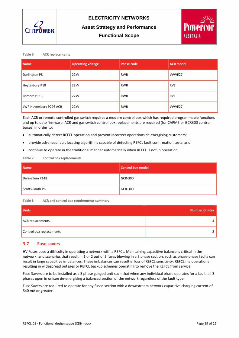
Table 6 ACR replacements
Name Operating voltage Phase code ACR model
Darlington P8 22kV RWB VWVE27
Heytesbury P18 22kV RWB RVE
Lismore P113 22kV RWB RVE
LWR Heytesbury P226 ACR 22kV RWB VWVE27
Each ACR or remote controlled gas switch requires a modern control box which has required programmable functions and up to date firmware. ACR and gas switch control box replacements are required (for CAPM5 or GCR300 control boxes) in order to:
• automatically detect REFCL operation and prevent incorrect operations de-energising customers;
• provide advanced fault locating algorithms capable of detecting REFCL fault confirmation tests; and
• continue to operate in the traditional manner automatically when REFCL is not in operation.
Table 7 Control box replacements
Name Control box model
Derinallum P148 GCR-300
Scotts South P6 GCR-300
Table 8 ACR and control box requirements summary
Units Number of sites
ACR replacements 4
Control box replacements 2
3.7 Fuse savers HV Fuses pose a difficulty in operating a network with a REFCL. Maintaining capacitive balance is critical in the network, and scenarios that result in 1 or 2 out of 3 fuses blowing in a 3 phase section, such as phase-phase faults can result in large capacitive imbalances. These imbalances can result in loss of REFCL sensitivity, REFCL maloperations resulting in widespread outages or REFCL backup schemes operating to remove the REFCL from service.
Fuse Savers are to be installed as a 3 phase ganged unit such that when any individual phase operates for a fault, all 3 phases open in unison de-energising a balanced section of the network regardless of the fault type.
Fuse Savers are required to operate for any fused section with a downstream network capacitive charging current of 540 mA or greater.
REFCL.01 - Functional design scope (CDN).docx Page 19 of 22
ELECTRICITY NETWORKS
Asset Strategy and Performance
Functional Scope
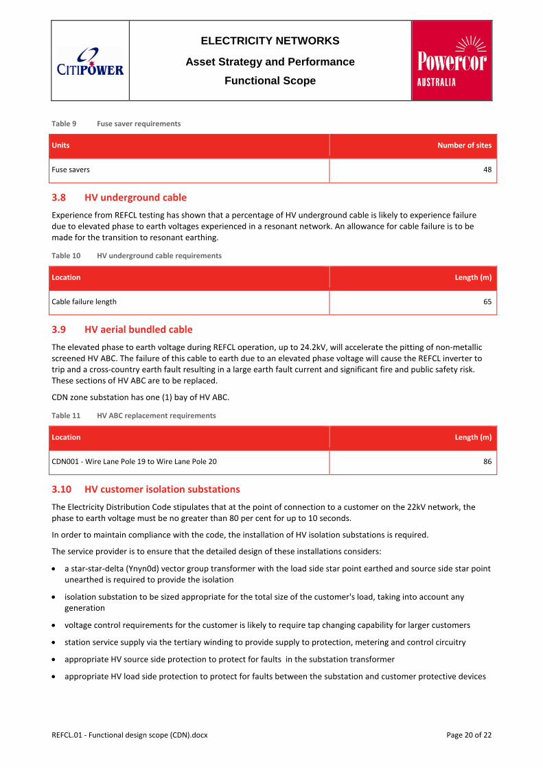
Table 9 Fuse saver requirements
Units Number of sites
Fuse savers 48
3.8 HV underground cable Experience from REFCL testing has shown that a percentage of HV underground cable is likely to experience failure due to elevated phase to earth voltages experienced in a resonant network. An allowance for cable failure is to be made for the transition to resonant earthing.
Table 10 HV underground cable requirements
Location Length (m)
Cable failure length 65
3.9 HV aerial bundled cable The elevated phase to earth voltage during REFCL operation, up to 24.2kV, will accelerate the pitting of non-metallic screened HV ABC. The failure of this cable to earth due to an elevated phase voltage will cause the REFCL inverter to trip and a cross-country earth fault resulting in a large earth fault current and significant fire and public safety risk. These sections of HV ABC are to be replaced.
CDN zone substation has one (1) bay of HV ABC.
Table 11 HV ABC replacement requirements
Location Length (m)
CDN001 - Wire Lane Pole 19 to Wire Lane Pole 20 86
3.10 HV customer isolation substations The Electricity Distribution Code stipulates that at the point of connection to a customer on the 22kV network, the phase to earth voltage must be no greater than 80 per cent for up to 10 seconds.
In order to maintain compliance with the code, the installation of HV isolation substations is required.
The service provider is to ensure that the detailed design of these installations considers:
• a star-star-delta (Ynyn0d) vector group transformer with the load side star point earthed and source side star point unearthed is required to provide the isolation
• isolation substation to be sized appropriate for the total size of the customer's load, taking into account any generation
• voltage control requirements for the customer is likely to require tap changing capability for larger customers
• station service supply via the tertiary winding to provide supply to protection, metering and control circuitry
• appropriate HV source side protection to protect for faults in the substation transformer
• appropriate HV load side protection to protect for faults between the substation and customer protective devices
REFCL.01 - Functional design scope (CDN).docx Page 20 of 22
ELECTRICITY NETWORKS
Asset Strategy and Performance
Functional Scope
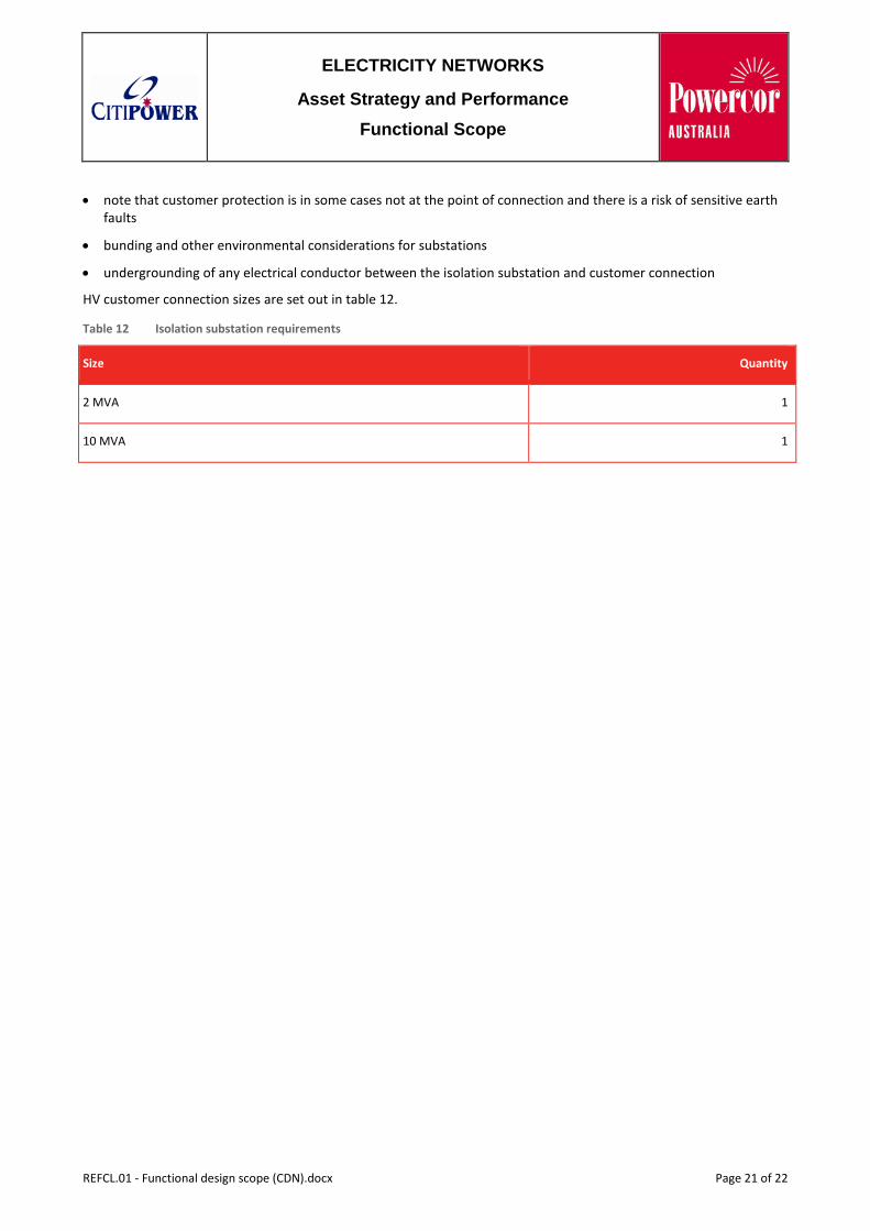
• note that customer protection is in some cases not at the point of connection and there is a risk of sensitive earth faults
• bunding and other environmental considerations for substations
• undergrounding of any electrical conductor between the isolation substation and customer connection
HV customer connection sizes are set out in table 12.
Table 12 Isolation substation requirements
Size Quantity
2 MVA 1
10 MVA 1
REFCL.01 - Functional design scope (CDN).docx Page 21 of 22
ELECTRICITY NETWORKS
Asset Strategy and Performance
Functional Scope
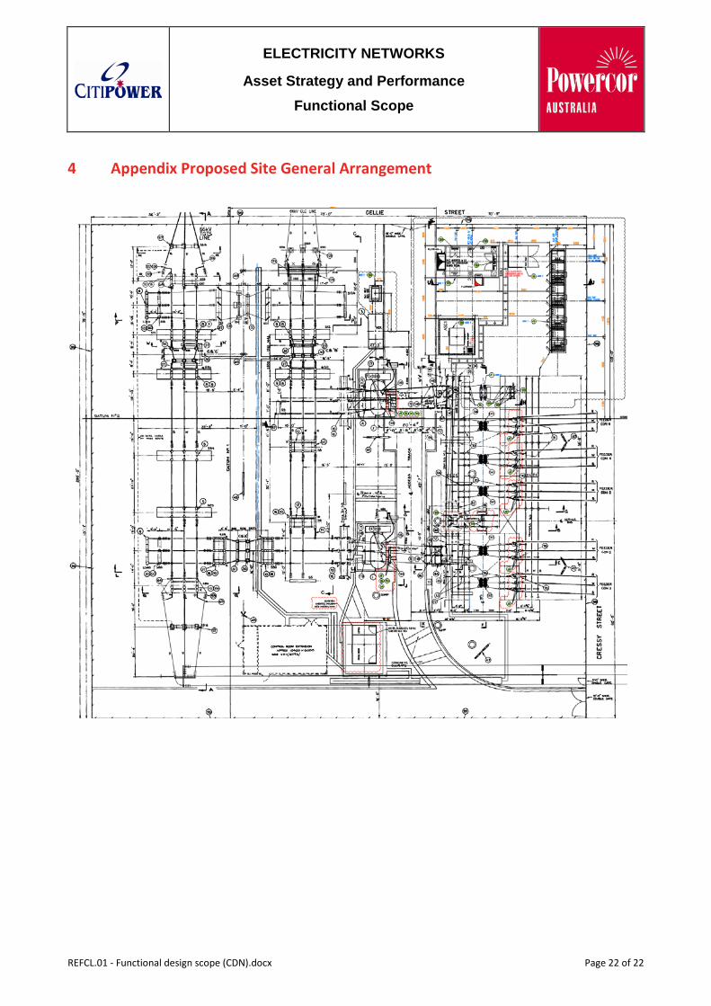
4 Appendix Proposed Site General Arrangement
REFCL.01 - Functional design scope (CDN).docx Page 22 of 22