electrical protection module 4 · system protection logic protection output electrical devices...
TRANSCRIPT

Electrical Protection


Electrical Faults
� Phase to phase� Phase to ground� Phase to phase to phase� Phase to phase to phase to ground

Purpose of Protection System
� Minimize damage� Leave unaffected equipment in-service� Maintain equipment operating limits� Maintain electrical system stability

Requirements of a Protection System
� Speed� Reliability� Security� Sensitivity

Some terms
� Over-current� Overload� Inverse time

Protection Zones

Simple Zone


Double Protection
"A" Bus Protection
"B" Bus Protection
CircuitBreaker
X
Bus
CircuitBreaker
Y
CT2
CT3
CT3
CT1
Bus Zone
CT4
CT2
CT4
CT1

ProtectionZones
xBusH2
Y
Bus Zone H2
Bus H1
Bus Zone H1
Bus Zone H3
BusH3
TransformerT1
ZoneT1
ZoneG1G1
TransformerSST1
ZoneSST1
SST1LV Bus
Bus Zone L1Bus L1

Breaker Failure
� Minimizes the amount of equipment removed from service in event of a failure
� Failure Determination� Not started opening in a certain time� Not open in a certain time� Current not broken in a certain time

Duplicate Protection Schemes
A Protection B Protection
Breaker X Breaker Y Device ZAction Q
Initiate InitiateTrip TripClose Close
PT
CT2
CT1 Electrical bus Electrical
System
ProtectionLogic
ProtectionOutput
ElectricalDevices
SystemInput

Bus Protection

Bus Protection
� Over-current� Differential � Back-up� Under voltage

Over-current Relay
I 1P
I 1S
CT 2000/5 A

Differential Protection
I 1P
I 1S
CT1 2000/5 A
I 2P
I 2S
CT2 2000/5 ABusH1
X Y
I = I1S = I2S
I = I1S = I2S
I = I1P = I2P
I 2SI 1S

Fault Conditions
I 1P
I 1S
CT1 2000/5 A
I 2P
I 2S
CT2 2000/5 ABusH1
X Y
I 1SI 2S
Fault

I 1P
CT 2000/5 A
I 2P
CT 2000/5 ABusH1
X Y
I 1S I 2S
I 1S
I 3S CT 2000/5 A
I 3P
T1
I 2S
I3S

Bus Protection Scheme
X
YLoadL2
LoadL1
T1
S Bus
Bus Differential Backup
Zone L1
Zone L2

Back-up relay
X
YLoad
L2
LoadL1
T1
S Bus
Over CurrentBackup Relay Differential
Relay

Bus Under Voltage Protection
Armature shown in the non-energized (trip) position
NormallyOpenContacts
To PotentialTransformer


Bus Protection
� Over-current� Differential � Back-up� Under voltage

Transformer Protection

Transformer Protection
� Instantaneous� Differential� Gas� Thermal Overload� Ground

Transformer Characteristics
� High magnetizing inrush currents� Ratio mismatch with CTs aggravated by
tap-changers� Phase shifts� Transformers are affected by over-fluxing� Affected by over-temperature

Transformer Zone
T1
CT2
CT3
CT4
CT1
T1 Zone
CT3
CT1
CT4
CT2
"A" Transformer Protection
"B" Transformer Protection

Differential
I 1P
I 1S
CT1
I 2P
I 2S
CT2
I = I1S = I2S
T1
Operate Coil
Restraint Coil
Restraint Coil
I 1S I 2S


Gas Relay

Winding Temperature

Ground Fault Protection
CT1
T1
GroundBackup
DifferentialRelay
CT2
TransformerStar Point
GroundCT
IN
IN
CT3IF

Transformer Protection
� Instantaneous� Differential� Gas� Thermal Overload� Ground

Motor Protection
Service Factor
� Continuous allowable overload� Many motors some with a power rating and a
service factor� A 10 HP motor with a service factor of 1.15
has a maximum continuous output of 11.5 HP

Motor Protection Summary
� Instantaneous Over-current� Stall� Thermal Overload� Phase Unbalance� Ground

Inverse Time Relay


Overload

Ground Fault Protection
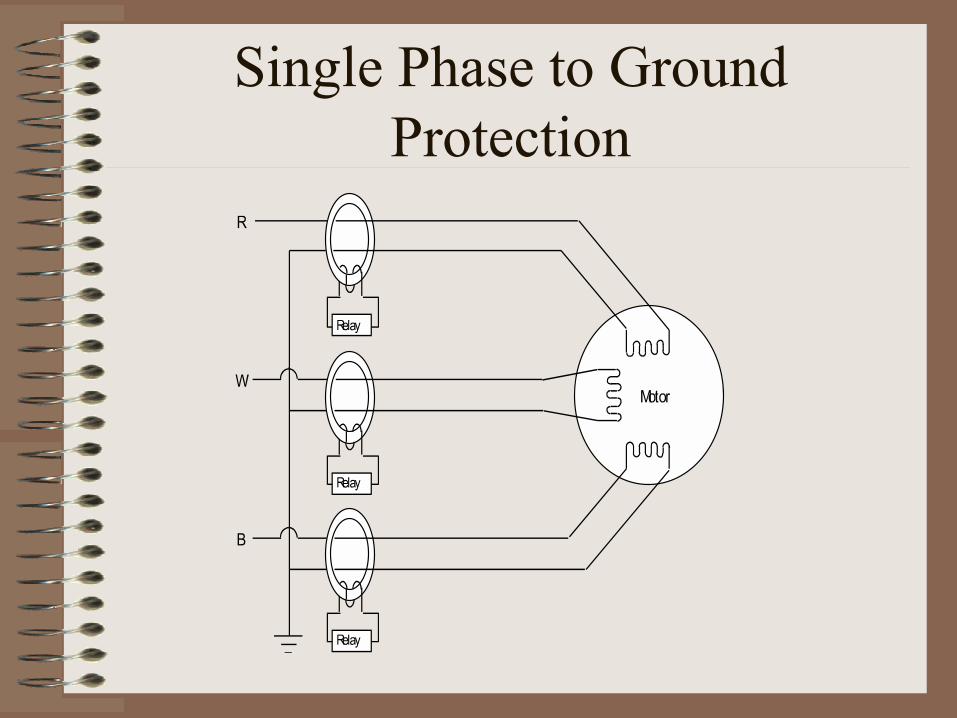
Single Phase to Ground Protection

Stalls

Thermal Overload & Phase Unbalance

Diagram of the Unit
Rotation as Ele me nts He at/Co ol
Phase Unbalance Contac tsLoad Indicating Po inte r
Adjus table Ove rload Contac t
Ove rloadSettingPo inte r
Shaft
He ater(e le c trical
c onnec tio ns no ts ho wn)
Ac tuating Bime tal
Ambie nt Co mpensating Bime tal
He at Shie ld


Motor Protection Summary
� Instantaneous Over-current� Stall� Thermal Overload� Phase Unbalance� Ground

Generator Protection
Classes of TG trips
� Class A� Trip generator breaker, field breaker and
turbine� Electrical trips before the output breakers
� Class B� Trip generator output but leave it supplying
station service� Electrical faults in the switchyard

Classes of TG trips
� Class C� Over excitation high V/Hz� Only used when generator is isolated from grid
� Class D� Trip turbine � Trip Generator after motoring is detected� Mechanical type turbine trips high condenser pressure

Generator Protection
� Over-current� Overload� Differential � Split phase differential � Ground� Rotor ground� Phase Unbalance� Low field� Under frequency� Out of Step� Reverse power

R
Prote ctionZo ne s
W B
Diffe re ntialRelay
Ne utral Co nne c tionto Gro und
a) He althy Phas e b) Faulted Phas e c ) Ope n Circ uit in the Phas e
Ge ne rator Terminals

Differential
G1
Operate Coil
Restraint Coil
Restraint Coil
I 1S I 2S
I 2P
I 2S
CT2
I 1S
CT1I 1P
GeneratorStar Point
Is = I1S = I2S
IP = I1P = I2P
To MainTransformer

Ground Fault Protection
T1
G1
GT1
Stator GroundRelay
IF

Rotor Ground Fault
Other Protections
� Phase Unbalance� Loss of field� Under frequency� Out of Step

Reverse Power
G
Re ve rsePowe rRe aly
V.T.

Generator Protection
� Over-current� Overload� Differential � Split phase differential � Ground� Rotor ground� Phase Unbalance� Low field� Under frequency� Out of Step� Reverse power

For You To Do