electrical and electronic - vasa · pdf fileprepared for wire & gas 2013 training...
TRANSCRIPT

Electrical and Electronic Diagnostics
For Vehicle Air Conditioning
Prepared for
WIRE & GAS 2013 Training Convention
Sam Nazarian
Jack Stepanian
Long Reef Garage
Circuit Diagrams Supplied with Courtesy of
All recorded measurements are believed to be true representation of and are based on unproblematic motor vehicle management. ALL rights are reserved to make changes without prior notice. ALL conditions prescribed under the copyright act are reserved. No
part of this document may be reproduced or transmitted in any form or by any means, electronic or mechanical without prior expressed written notice, it is an offence
For Circuit diagrams, connector Location/end views and pin configurations please see
TAT, Rellim Bookworks, Repco Auto Tech Encyclopedia, Auto Data, and Automotive Service Solution

Prepared for WIRE & GAS 2013 Training Convention Electrical & Electronic Diagnostics for Vehicle Air conditioning Authors: Sam Nazarian & Jack Stepanian
All Rights Reserved Long Reef Garage PTY LTD All recorded measurements are believed to be true representation of and are based on unproblematic motor vehicle management. ALL rights are reserved to make changes without prior
notice. ALL conditions prescribed under the copyright act are reserved. No part of this document may be reproduced or transmitted in any form or by any means, electronic or mechanical without prior expressed written notice, it is an offence – All intelectuall materials are the property of the authors.
For Circuit diagrams, connector Location/end views and pin configurations please see TAT, Relim Bookworks, Repco Auto Tech Encyclopedia, Auto Data, Automotive Service Solution
2 of 54
Acknowledgement and references Authors wish to acknowledge that information gathered and collated for the purpose of research and development of this is training manual was based on actual measurements from a BA Ford Falcon vehicle
For Circuit diagrams, connector Location/end views and pin configurations please see TAT, Rellim, Bookworks, Repco Auto Tech Encyclopedia, Auto Data and Automotive Service Solution
Information contained herewith is limited to Engine management and CAN BUS. For more information regarding Pin configuration, Circuit Diagrams and location of connectors please kindly contact above mentioned organizations. Information contained within is NOT intended to be used as a ‘stand alone’ training manual and or a reference material– rather as a reference material (an adjunct) to be used during training session. Websites accessed to gain information regarding Engine management and CAN BUS Operation, Configuration and Topology please, see ‘References’ at end of this training manual. Special thanks to Jeff Smit (Technical editor TAT) and Ken Newton (TAT) for their implausible editorial assistance, encouragement and moral support.
Authors would also like to thank the following organization for their unparalleled support and assistance in providing information, access to data and use of their scan tools (herewith contained in this training manual);
The Automotive Technician
(TAT)
Repco
Auto Tech Encyclopedia
Auto Data PC Based
DATA Base
Hanatech G-Scan
Mount Auto EQ
Autel
MaxDas InterEquip
Automotive
Service Solution
Relim
Bookworks Wiring Diagrams
Pico-Scope
PC USB Mount Auto EQ

Prepared for WIRE & GAS 2013 Training Convention Electrical & Electronic Diagnostics for Vehicle Air conditioning Authors: Sam Nazarian & Jack Stepanian
All Rights Reserved Long Reef Garage PTY LTD All recorded measurements are believed to be true representation of and are based on unproblematic motor vehicle management. ALL rights are reserved to make changes without prior
notice. ALL conditions prescribed under the copyright act are reserved. No part of this document may be reproduced or transmitted in any form or by any means, electronic or mechanical without prior expressed written notice, it is an offence – All intelectuall materials are the property of the authors.
For Circuit diagrams, connector Location/end views and pin configurations please see TAT, Relim Bookworks, Repco Auto Tech Encyclopedia, Auto Data, Automotive Service Solution
3 of 54
Technician A
Technician B
Starting point
Pool of Knowledge
Gained Knowledge
Gained Knowledge
The essence of diagnostics is to apply gathered knowledge to maximize honing-in skills and minimize guess-work, thus avoiding unnecessary replacement of components.
After all, it isn’t what you know but rather it is the application of knowledge that makes the difference in diagnosing symptomatic vehicles

Prepared for WIRE & GAS 2013 Training Convention Electrical & Electronic Diagnostics for Vehicle Air conditioning Authors: Sam Nazarian & Jack Stepanian
All Rights Reserved Long Reef Garage PTY LTD All recorded measurements are believed to be true representation of and are based on unproblematic motor vehicle management. ALL rights are reserved to make changes without prior
notice. ALL conditions prescribed under the copyright act are reserved. No part of this document may be reproduced or transmitted in any form or by any means, electronic or mechanical without prior expressed written notice, it is an offence – All intelectuall materials are the property of the authors.
For Circuit diagrams, connector Location/end views and pin configurations please see TAT, Relim Bookworks, Repco Auto Tech Encyclopedia, Auto Data, Automotive Service Solution
4 of 54
Basic steps of Diagnosis Initial BASIC checks
1. Listen to customer’s complaint 2. Listen to car’s complaint 3. Carry out basic checks 4. Check battery supply, charge voltage (AC, DC waveform) 5. Check battery Grounds (disable car from start – Post to block, chassis, terminal) 6. Carry out basic Wiggle test (wiggle connectors and electrical cables for possible bad connectivity) 7. Listen for Vacuum leaks 8. Observe possible restriction (inlet, exhaust) 9. Extract OBD generic diagnostic Trouble codes
In-Depth Diagnostics
1. Inform Customer 2. Obtain budget commitment 3. Extract specific diagnostic Trouble codes from each and every control module on the CAN BUS 4. Interrogate Diagnostic trouble codes and identify frequent codes (common codes yet reported by differing control
units) 5. Determine whether symptom is due to ‘failing’ CAN BUS communication and or specific control unit (sensor/control) 6. If symptom is CAN BUS related: Obtain Block diagram of CAN BUS Topology 7. If symptom is specific control unit ( sensor/control) related: obtain circuit diagram 8. Measure supply and ground voltages of that specific ECM and Capture waveforms (of suspect component) 9. Keep customer informed of progress 10. Prepare Invoice (Diagnosis / Remove and replace) 11. Inform customer of final costing 12. Hand over (show photos, captured waveforms colored circuit diagrams and other supporting material)
PRE
POST

Prepared for WIRE & GAS 2013 Training Convention Electrical & Electronic Diagnostics for Vehicle Air conditioning Authors: Sam Nazarian & Jack Stepanian
All Rights Reserved Long Reef Garage PTY LTD All recorded measurements are believed to be true representation of and are based on unproblematic motor vehicle management. ALL rights are reserved to make changes without prior
notice. ALL conditions prescribed under the copyright act are reserved. No part of this document may be reproduced or transmitted in any form or by any means, electronic or mechanical without prior expressed written notice, it is an offence – All intelectuall materials are the property of the authors.
For Circuit diagrams, connector Location/end views and pin configurations please see TAT, Relim Bookworks, Repco Auto Tech Encyclopedia, Auto Data, Automotive Service Solution
5 of 54
The Process of Diagnostics Triangulation Technique 1 – Carry out a system wide DTC check (note, each and every DTC) 2 – Communicate with each and every control unit and pay particular attention as to which control unit is ‘responsible’ for reporting the DTC (if any) and carry out actuation test based on customers’ concern/symptom 3 – Obtain circuit diagram and interrogate circuitry by:
Query the following: ‘should this component fail - what will the symptom be’?
And then carry out specific component tests based on customer symptom/complain.
Minimum MUST HAVE arsenals (access to the following):
Scan Tool
Circuit Diagram (CAN BUS Topology, specific diagrams and so on)
Location of component’s (Sensors, Connectors, Control units)
Oscilloscope
1
System Wide Diagnostic Check
Communicate with each and every control unit
2
Obtain Circuit Diagram
3

Prepared for WIRE & GAS 2013 Training Convention Electrical & Electronic Diagnostics for Vehicle Air conditioning Authors: Sam Nazarian & Jack Stepanian
All Rights Reserved Long Reef Garage PTY LTD All recorded measurements are believed to be true representation of and are based on unproblematic motor vehicle management. ALL rights are reserved to make changes without prior
notice. ALL conditions prescribed under the copyright act are reserved. No part of this document may be reproduced or transmitted in any form or by any means, electronic or mechanical without prior expressed written notice, it is an offence – All intelectuall materials are the property of the authors.
For Circuit diagrams, connector Location/end views and pin configurations please see TAT, Relim Bookworks, Repco Auto Tech Encyclopedia, Auto Data, Automotive Service Solution
6 of 54
1
System Wide Diagnostic Check
Perform system wide DTC check, note, each and every DTC
1
2
3
4
5
6
7
8
9
1 – 1
2005, Holden, Commodore VZ, 3.6, DLC
10
11

Prepared for WIRE & GAS 2013 Training Convention Electrical & Electronic Diagnostics for Vehicle Air conditioning Authors: Sam Nazarian & Jack Stepanian
All Rights Reserved Long Reef Garage PTY LTD All recorded measurements are believed to be true representation of and are based on unproblematic motor vehicle management. ALL rights are reserved to make changes without prior
notice. ALL conditions prescribed under the copyright act are reserved. No part of this document may be reproduced or transmitted in any form or by any means, electronic or mechanical without prior expressed written notice, it is an offence – All intelectuall materials are the property of the authors.
For Circuit diagrams, connector Location/end views and pin configurations please see TAT, Relim Bookworks, Repco Auto Tech Encyclopedia, Auto Data, Automotive Service Solution
7 of 54
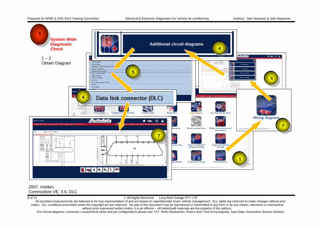
1
System Wide Diagnostic Check
1 – 2 Obtain diagram
2007, Holden, Commodore VE, 3.6, DLC
Air Conditioning Controls and CAN BUS (controller Area Network Bidirectional Universal system) Obtain CAN BUS Topology by accessing automotive data-base of CAN BUS diagram
Prepared for WIRE & GAS 2013 Training Convention Electrical & Electronic Diagnostics for Vehicle Air conditioning Authors: Sam Nazarian & Jack Stepanian
All Rights Reserved Long Reef Garage PTY LTD All recorded measurements are believed to be true representation of and are based on unproblematic motor vehicle management. ALL rights are reserved to make changes without prior
notice. ALL conditions prescribed under the copyright act are reserved. No part of this document may be reproduced or transmitted in any form or by any means, electronic or mechanical without prior expressed written notice, it is an offence – All intelectuall materials are the property of the authors.
For Circuit diagrams, connector Location/end views and pin configurations please see TAT, Relim Bookworks, Repco Auto Tech Encyclopedia, Auto Data, Automotive Service Solution
8 of 54
1
System Wide Diagnostic Check
1 – 2 Obtain Diagram
2007, Holden, Commodore VE, 3.6, DLC
1
2
3
4
5
6
7

Prepared for WIRE & GAS 2013 Training Convention Electrical & Electronic Diagnostics for Vehicle Air conditioning Authors: Sam Nazarian & Jack Stepanian
All Rights Reserved Long Reef Garage PTY LTD All recorded measurements are believed to be true representation of and are based on unproblematic motor vehicle management. ALL rights are reserved to make changes without prior
notice. ALL conditions prescribed under the copyright act are reserved. No part of this document may be reproduced or transmitted in any form or by any means, electronic or mechanical without prior expressed written notice, it is an offence – All intelectuall materials are the property of the authors.
For Circuit diagrams, connector Location/end views and pin configurations please see TAT, Relim Bookworks, Repco Auto Tech Encyclopedia, Auto Data, Automotive Service Solution
9 of 54
Plug Scan tool into DLC and make sure that scan tool ‘powers-up’ If not, measure supply (pin 16) and grounds at (pins 4 and 5) DLC
2007, Holden, Commodore VE, 3.6, DLC
1
System Wide Diagnostic Check
1 – 3

Prepared for WIRE & GAS 2013 Training Convention Electrical & Electronic Diagnostics for Vehicle Air conditioning Authors: Sam Nazarian & Jack Stepanian
All Rights Reserved Long Reef Garage PTY LTD All recorded measurements are believed to be true representation of and are based on unproblematic motor vehicle management. ALL rights are reserved to make changes without prior
notice. ALL conditions prescribed under the copyright act are reserved. No part of this document may be reproduced or transmitted in any form or by any means, electronic or mechanical without prior expressed written notice, it is an offence – All intelectuall materials are the property of the authors.
For Circuit diagrams, connector Location/end views and pin configurations please see TAT, Relim Bookworks, Repco Auto Tech Encyclopedia, Auto Data, Automotive Service Solution
10 of 54
Plug Scan tool into DLC and make sure that scan tool ‘powers-up’ If not, measure supply (pin 16) and grounds at (pins 4 and 5) DLC
2 volt / div
1 second / div
100 mv / div
1 second / div
2007, Holden, Commodore VE, 3.6, DLC
1 – 4
1
System Wide Diagnostic Check

Prepared for WIRE & GAS 2013 Training Convention Electrical & Electronic Diagnostics for Vehicle Air conditioning Authors: Sam Nazarian & Jack Stepanian
All Rights Reserved Long Reef Garage PTY LTD All recorded measurements are believed to be true representation of and are based on unproblematic motor vehicle management. ALL rights are reserved to make changes without prior
notice. ALL conditions prescribed under the copyright act are reserved. No part of this document may be reproduced or transmitted in any form or by any means, electronic or mechanical without prior expressed written notice, it is an offence – All intelectuall materials are the property of the authors.
For Circuit diagrams, connector Location/end views and pin configurations please see TAT, Relim Bookworks, Repco Auto Tech Encyclopedia, Auto Data, Automotive Service Solution
11 of 54
Identify and note each and every control unit in the diagram
Data BUS connector
DLC
TCM
ABS
Head Lamp Leveling control
ECM
AC
TPMS
Seat adj cont mod
Park contr
SRS
Alarm
NAV
Mobile
Ins PNL
Auto
SAS Multi -
Function Control
Unit
2007, Holden, Commodore VE, 3.6, DLC
1
System Wide Diagnostic Check
1 – 5

Prepared for WIRE & GAS 2013 Training Convention Electrical & Electronic Diagnostics for Vehicle Air conditioning Authors: Sam Nazarian & Jack Stepanian
All Rights Reserved Long Reef Garage PTY LTD All recorded measurements are believed to be true representation of and are based on unproblematic motor vehicle management. ALL rights are reserved to make changes without prior
notice. ALL conditions prescribed under the copyright act are reserved. No part of this document may be reproduced or transmitted in any form or by any means, electronic or mechanical without prior expressed written notice, it is an offence – All intelectuall materials are the property of the authors.
For Circuit diagrams, connector Location/end views and pin configurations please see TAT, Relim Bookworks, Repco Auto Tech Encyclopedia, Auto Data, Automotive Service Solution
12 of 54
Identify resistor LOCATIONS of High speed CAN BUS (Controller Area Network Bidirectional Universal Signal) terminating resistors of 120 Ohms each.
Data BUS connector
DLC
TCM
ABS
Head Lamp Leveling control
ECM
AC
TPMS
Seat adj cont mod
Park cont
SRS
Alarm
NAV
Mobile
Ins
PNL
SAS Multi -
Function Control
Unit
Terminating resister 120
Terminating resister 120
2007, Holden, Commodore VE, 3.6, DLC
1
System Wide Diagnostic Check
1 – 6

Prepared for WIRE & GAS 2013 Training Convention Electrical & Electronic Diagnostics for Vehicle Air conditioning Authors: Sam Nazarian & Jack Stepanian
All Rights Reserved Long Reef Garage PTY LTD All recorded measurements are believed to be true representation of and are based on unproblematic motor vehicle management. ALL rights are reserved to make changes without prior
notice. ALL conditions prescribed under the copyright act are reserved. No part of this document may be reproduced or transmitted in any form or by any means, electronic or mechanical without prior expressed written notice, it is an offence – All intelectuall materials are the property of the authors.
For Circuit diagrams, connector Location/end views and pin configurations please see TAT, Relim Bookworks, Repco Auto Tech Encyclopedia, Auto Data, Automotive Service Solution
13 of 54
Identify and trace High side of High speed CAN BUS
Data BUS connector
DLC
TCM
ABS
Head Lamp Leveling control
ECM
AC
TPMS
Seat adj cont mod
Park cont
SRS
Alarm
NAV
Mobile
Ins
PNL
SAS Multi -
Function Control
Unit
Terminating resister 120
Terminating resister 120
2007, Holden, Commodore VE, 3.6, DLC
1
System Wide Diagnostic Check
1 – 7
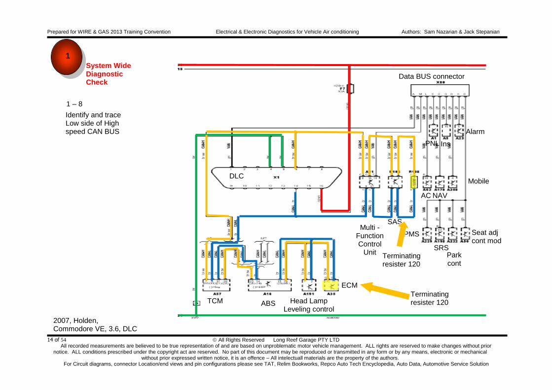
Prepared for WIRE & GAS 2013 Training Convention Electrical & Electronic Diagnostics for Vehicle Air conditioning Authors: Sam Nazarian & Jack Stepanian
All Rights Reserved Long Reef Garage PTY LTD All recorded measurements are believed to be true representation of and are based on unproblematic motor vehicle management. ALL rights are reserved to make changes without prior
notice. ALL conditions prescribed under the copyright act are reserved. No part of this document may be reproduced or transmitted in any form or by any means, electronic or mechanical without prior expressed written notice, it is an offence – All intelectuall materials are the property of the authors.
For Circuit diagrams, connector Location/end views and pin configurations please see TAT, Relim Bookworks, Repco Auto Tech Encyclopedia, Auto Data, Automotive Service Solution
14 of 54
Identify and trace Low side of High speed CAN BUS
Data BUS connector
DLC
TCM
ABS
Head Lamp Leveling control
ECM
AC
TPMS
Seat adj cont mod
Park cont
SRS
Alarm
NAV
Mobile
Ins
PNL
SAS Multi -
Function Control
Unit
Terminating resister 120
Terminating resister 120
2007, Holden, Commodore VE, 3.6, DLC
1
System Wide Diagnostic Check
1 – 8

Prepared for WIRE & GAS 2013 Training Convention Electrical & Electronic Diagnostics for Vehicle Air conditioning Authors: Sam Nazarian & Jack Stepanian
All Rights Reserved Long Reef Garage PTY LTD All recorded measurements are believed to be true representation of and are based on unproblematic motor vehicle management. ALL rights are reserved to make changes without prior
notice. ALL conditions prescribed under the copyright act are reserved. No part of this document may be reproduced or transmitted in any form or by any means, electronic or mechanical without prior expressed written notice, it is an offence – All intelectuall materials are the property of the authors.
For Circuit diagrams, connector Location/end views and pin configurations please see TAT, Relim Bookworks, Repco Auto Tech Encyclopedia, Auto Data, Automotive Service Solution
15 of 54
Measure resistance between High side of High speed BUS (pin 6) and Low side if the High speed BUS (pin 14) and since two 120 Ohm resistors are in parallel then the measured resistance MUST be 60 Ohms (approx..) Please note: for resistance measurements there must NOT be any voltage activities. The High speed BBUS must be ‘SLEEP’. Allow 3 minutes after Ignition key out of barrel to allow voltage activities to cease
Data BUS connector
DLC
TCM
ABS
Head Lamp Leveling control
ECM
AC
TPMS
Seat adj cont mod
Park cont
SRS
Alarm
NAV
Mobile
Ins
PNL
SAS Multi -
Function Control
Unit
Terminating resister 120
Terminating resister 120
2007, Holden, Commodore VE, 3.6, DLC
1
System Wide Diagnostic Check
1 – 9

Prepared for WIRE & GAS 2013 Training Convention Electrical & Electronic Diagnostics for Vehicle Air conditioning Authors: Sam Nazarian & Jack Stepanian
All Rights Reserved Long Reef Garage PTY LTD All recorded measurements are believed to be true representation of and are based on unproblematic motor vehicle management. ALL rights are reserved to make changes without prior
notice. ALL conditions prescribed under the copyright act are reserved. No part of this document may be reproduced or transmitted in any form or by any means, electronic or mechanical without prior expressed written notice, it is an offence – All intelectuall materials are the property of the authors.
For Circuit diagrams, connector Location/end views and pin configurations please see TAT, Relim Bookworks, Repco Auto Tech Encyclopedia, Auto Data, Automotive Service Solution
16 of 54
DataBUS connector
DLC
TCM
ABS
Head Lamp Leveling control
ECM
AC
TPMS
Seat adj cont mod
Park cont
SRS
Alarm
NAV
Mobile
Ins
PNL
SAS Multi -
Function Control
Unit
Terminating resister 120
Terminating resister 120
2007, Holden, Commodore VE, 3.6, DLC
Measure waveform of High side of High speed BUS (pin 6) and Low side if the High speed BUS (pin 14) and observe ‘fidelity’ of the signal High side of high speed BUS should oscillate between from 2.5 volts up to 3.5 volts (approx.) Similarly the Low side of the high speed BUS should oscillates from 2.5 volts down to 1.5 volts (approx.)
1 volt / div
20 micro sec / div
1
System Wide Diagnostic Check
1 – 10
1 volt / div
20 micro sec / div

Prepared for WIRE & GAS 2013 Training Convention Electrical & Electronic Diagnostics for Vehicle Air conditioning Authors: Sam Nazarian & Jack Stepanian
All Rights Reserved Long Reef Garage PTY LTD All recorded measurements are believed to be true representation of and are based on unproblematic motor vehicle management. ALL rights are reserved to make changes without prior
notice. ALL conditions prescribed under the copyright act are reserved. No part of this document may be reproduced or transmitted in any form or by any means, electronic or mechanical without prior expressed written notice, it is an offence – All intelectuall materials are the property of the authors.
For Circuit diagrams, connector Location/end views and pin configurations please see TAT, Relim Bookworks, Repco Auto Tech Encyclopedia, Auto Data, Automotive Service Solution
17 of 54
Identify the module that is assigned as Gateway Gateway is the ‘mediator’ and or the ‘translator’ (if you will) between High and low speed BUSs
Data BUS connector
DLC
TCM
ABS
Head Lamp Leveling control
ECM
AC
TPMS
Seat adj cont mod
Park cont
SRS
Alarm
NAV
Mobile
Ins
PNL
SAS
Multi -Function Control Unit is
THE GATEWAY
Terminating resister 120
Terminating resister 120
2007, Holden, Commodore VE, 3.6, DLC
1
System Wide Diagnostic Check
1 – 11

Prepared for WIRE & GAS 2013 Training Convention Electrical & Electronic Diagnostics for Vehicle Air conditioning Authors: Sam Nazarian & Jack Stepanian
All Rights Reserved Long Reef Garage PTY LTD All recorded measurements are believed to be true representation of and are based on unproblematic motor vehicle management. ALL rights are reserved to make changes without prior
notice. ALL conditions prescribed under the copyright act are reserved. No part of this document may be reproduced or transmitted in any form or by any means, electronic or mechanical without prior expressed written notice, it is an offence – All intelectuall materials are the property of the authors.
For Circuit diagrams, connector Location/end views and pin configurations please see TAT, Relim Bookworks, Repco Auto Tech Encyclopedia, Auto Data, Automotive Service Solution
18 of 54
Trace Low Speed BUS
Data BUS connector
DLC
TCM
ABS
Head Lamp Leveling control
ECM
AC
TPMS
Seat adj cont mod
Park cont
SRS
Alarm
NAV
Mobile
Ins
PNL
SAS
Multi -Function Control Unit is
THE GATEWAY
Terminating resister 120
Terminating resister 120
2007, Holden, Commodore VE, 3.6, DLC
1
System Wide Diagnostic Check
1 – 12

Prepared for WIRE & GAS 2013 Training Convention Electrical & Electronic Diagnostics for Vehicle Air conditioning Authors: Sam Nazarian & Jack Stepanian
All Rights Reserved Long Reef Garage PTY LTD All recorded measurements are believed to be true representation of and are based on unproblematic motor vehicle management. ALL rights are reserved to make changes without prior
notice. ALL conditions prescribed under the copyright act are reserved. No part of this document may be reproduced or transmitted in any form or by any means, electronic or mechanical without prior expressed written notice, it is an offence – All intelectuall materials are the property of the authors.
For Circuit diagrams, connector Location/end views and pin configurations please see TAT, Relim Bookworks, Repco Auto Tech Encyclopedia, Auto Data, Automotive Service Solution
19 of 54
Measure waveform of Low Speed BUS and observe fidelity of signal
Data BUS connector
DLC
TCM
ABS
Head Lamp Leveling control
ECM
AC
TPMS
Seat adj cont mod
Park cont
SRS
Alarm
NAV
Mobile
Ins
PNL
SAS
Multi -Function Control Unit is
THE GATEWAY
Terminating resister 120
Terminating resister 120
2007, Holden, Commodore VE, 3.6, DLC
2 volt / div 1 sec / div Insert Key IN, crank
and start engine
2 volt / div 1 sec / div
5 min after IGN OFF
2 volt / div 40 milli sec / div
Whilst engine running
2 volt / div 0.2 milli sec / div Whilst engine running
1
System Wide Diagnostic Check
1 – 13

Prepared for WIRE & GAS 2013 Training Convention Electrical & Electronic Diagnostics for Vehicle Air conditioning Authors: Sam Nazarian & Jack Stepanian
All Rights Reserved Long Reef Garage PTY LTD All recorded measurements are believed to be true representation of and are based on unproblematic motor vehicle management. ALL rights are reserved to make changes without prior
notice. ALL conditions prescribed under the copyright act are reserved. No part of this document may be reproduced or transmitted in any form or by any means, electronic or mechanical without prior expressed written notice, it is an offence – All intelectuall materials are the property of the authors.
For Circuit diagrams, connector Location/end views and pin configurations please see TAT, Relim Bookworks, Repco Auto Tech Encyclopedia, Auto Data, Automotive Service Solution
20 of 54
Communicate with each and every control unit and pay particular attention as to which control unit is ‘responsible’ for reporting the DTC (if any) and carry out actuation test based on customers’ concern/symptom Log in-to Autodata
Select year, Manufacturer, Mode range, engine
Wiring Diagram
ADDITIONAL Circuit Diagram
Data Link Connector (DLC)
2 – 1
Communicate with each and every control unit and carry out actuation test unit
2

Prepared for WIRE & GAS 2013 Training Convention Electrical & Electronic Diagnostics for Vehicle Air conditioning Authors: Sam Nazarian & Jack Stepanian
All Rights Reserved Long Reef Garage PTY LTD All recorded measurements are believed to be true representation of and are based on unproblematic motor vehicle management. ALL rights are reserved to make changes without prior
notice. ALL conditions prescribed under the copyright act are reserved. No part of this document may be reproduced or transmitted in any form or by any means, electronic or mechanical without prior expressed written notice, it is an offence – All intelectuall materials are the property of the authors.
For Circuit diagrams, connector Location/end views and pin configurations please see TAT, Relim Bookworks, Repco Auto Tech Encyclopedia, Auto Data, Automotive Service Solution
21 of 54
Trace and highlight supply (pin 16) and grounds at (pins 4 and 5) DLC
2005, Holden, Commodore VZ, 3.6, DLC
2 – 2
Communicate with each and every control unit and carry out actuation test unit
2

Prepared for WIRE & GAS 2013 Training Convention Electrical & Electronic Diagnostics for Vehicle Air conditioning Authors: Sam Nazarian & Jack Stepanian
All Rights Reserved Long Reef Garage PTY LTD All recorded measurements are believed to be true representation of and are based on unproblematic motor vehicle management. ALL rights are reserved to make changes without prior
notice. ALL conditions prescribed under the copyright act are reserved. No part of this document may be reproduced or transmitted in any form or by any means, electronic or mechanical without prior expressed written notice, it is an offence – All intelectuall materials are the property of the authors.
For Circuit diagrams, connector Location/end views and pin configurations please see TAT, Relim Bookworks, Repco Auto Tech Encyclopedia, Auto Data, Automotive Service Solution
22 of 54
2005, Holden, Commodore VZ, 3.6, DLC
Identify and note each and every control unit in the diagram
TCM
ABS
SAS
ECM
Interface Module
Inst Contr Mod
AC
Seat Adj
Contr Mod
SRS
Audio
Multi Funct Contr Unit
DLC
2 – 3
Communicate with each and every control unit and carry out actuation test unit
2

Prepared for WIRE & GAS 2013 Training Convention Electrical & Electronic Diagnostics for Vehicle Air conditioning Authors: Sam Nazarian & Jack Stepanian
All Rights Reserved Long Reef Garage PTY LTD All recorded measurements are believed to be true representation of and are based on unproblematic motor vehicle management. ALL rights are reserved to make changes without prior
notice. ALL conditions prescribed under the copyright act are reserved. No part of this document may be reproduced or transmitted in any form or by any means, electronic or mechanical without prior expressed written notice, it is an offence – All intelectuall materials are the property of the authors.
For Circuit diagrams, connector Location/end views and pin configurations please see TAT, Relim Bookworks, Repco Auto Tech Encyclopedia, Auto Data, Automotive Service Solution
23 of 54
2005, Holden, Commodore VZ, 3.6, DLC
TCM
ABS
SAS
ECM
Interface Module
Inst Contr Mod
AC
Seat Adj
Contr Mod
SRS
Audio
Multi Funct Contr Unit
DLC
Identify resistor LOCATIONS of High speed CAN BUS (Controller Area Network Bidirectional Universal Signal) terminating resistors of 120 Ohms each.
2 – 4
Communicate with each and every control unit and carry out actuation test unit
2

Prepared for WIRE & GAS 2013 Training Convention Electrical & Electronic Diagnostics for Vehicle Air conditioning Authors: Sam Nazarian & Jack Stepanian
All Rights Reserved Long Reef Garage PTY LTD All recorded measurements are believed to be true representation of and are based on unproblematic motor vehicle management. ALL rights are reserved to make changes without prior
notice. ALL conditions prescribed under the copyright act are reserved. No part of this document may be reproduced or transmitted in any form or by any means, electronic or mechanical without prior expressed written notice, it is an offence – All intelectuall materials are the property of the authors.
For Circuit diagrams, connector Location/end views and pin configurations please see TAT, Relim Bookworks, Repco Auto Tech Encyclopedia, Auto Data, Automotive Service Solution
24 of 54
2005, Holden, Commodore VZ, 3.6, DLC
TCM
ABS
SAS
ECM
Interface Module
Inst Contr Mod
AC
Seat Adj
Contr Mod
SRS
Audio
Multi Funct Contr Unit
DLC
2005, Holden, Commodore VZ, 3.6, DLC
TCM
ABS
SAS
ECM
Interface Module
Inst Contr Mod
AC
Seat Adj
Contr Mod
SRS
Audio
Multi Funct Contr Unit
DLC
Identify and trace High side of High speed CAN BUS
2 – 5
Communicate with each and every control unit and carry out actuation test unit
2

Prepared for WIRE & GAS 2013 Training Convention Electrical & Electronic Diagnostics for Vehicle Air conditioning Authors: Sam Nazarian & Jack Stepanian
All Rights Reserved Long Reef Garage PTY LTD All recorded measurements are believed to be true representation of and are based on unproblematic motor vehicle management. ALL rights are reserved to make changes without prior
notice. ALL conditions prescribed under the copyright act are reserved. No part of this document may be reproduced or transmitted in any form or by any means, electronic or mechanical without prior expressed written notice, it is an offence – All intelectuall materials are the property of the authors.
For Circuit diagrams, connector Location/end views and pin configurations please see TAT, Relim Bookworks, Repco Auto Tech Encyclopedia, Auto Data, Automotive Service Solution
25 of 54
2005, Holden, Commodore VZ, 3.6, DLC
TCM
ABS
SAS
ECM
Interface Module
Inst Contr Mod
AC
Seat Adj
Contr Mod
SRS
Audio
Multi Funct Contr Unit
DLC
2005, Holden, Commodore VZ, 3.6, DLC
TCM
ABS
SAS
ECM
Interface Module
Inst Contr Mod
AC
Seat Adj
Contr Mod
SRS
Audio
Multi Funct Contr Unit
DLC
Identify and trace Low side of High speed CAN BUS
2 – 6
Communicate with each and every control unit and carry out actuation test unit
2

Prepared for WIRE & GAS 2013 Training Convention Electrical & Electronic Diagnostics for Vehicle Air conditioning Authors: Sam Nazarian & Jack Stepanian
All Rights Reserved Long Reef Garage PTY LTD All recorded measurements are believed to be true representation of and are based on unproblematic motor vehicle management. ALL rights are reserved to make changes without prior
notice. ALL conditions prescribed under the copyright act are reserved. No part of this document may be reproduced or transmitted in any form or by any means, electronic or mechanical without prior expressed written notice, it is an offence – All intelectuall materials are the property of the authors.
For Circuit diagrams, connector Location/end views and pin configurations please see TAT, Relim Bookworks, Repco Auto Tech Encyclopedia, Auto Data, Automotive Service Solution
26 of 54
2005, Holden, Commodore VZ, 3.6, DLC
TCM
ABS
SAS
ECM
Interface Module
Inst Contr Mod
AC
Seat Adj
Contr Mod
SRS
Audio
Multi Funct Contr Unit
DLC
2005, Holden, Commodore VZ, 3.6, DLC
TCM
ABS
SAS
ECM
Interface Module
Inst Contr Mod
AC
Seat Adj
Contr Mod
SRS
Audio
Multi Funct Contr Unit
DLC
Identify the module that is assigned as Gateway Gateway is the ‘mediator’ and or the ‘translator’ (if you will) between High and low speed BUSs
Interface Module
is THE GATEWAY
2 – 7
Communicate with each and every control unit and carry out actuation test unit
2

Prepared for WIRE & GAS 2013 Training Convention Electrical & Electronic Diagnostics for Vehicle Air conditioning Authors: Sam Nazarian & Jack Stepanian
All Rights Reserved Long Reef Garage PTY LTD All recorded measurements are believed to be true representation of and are based on unproblematic motor vehicle management. ALL rights are reserved to make changes without prior
notice. ALL conditions prescribed under the copyright act are reserved. No part of this document may be reproduced or transmitted in any form or by any means, electronic or mechanical without prior expressed written notice, it is an offence – All intelectuall materials are the property of the authors.
For Circuit diagrams, connector Location/end views and pin configurations please see TAT, Relim Bookworks, Repco Auto Tech Encyclopedia, Auto Data, Automotive Service Solution
27 of 54
2005, Holden, Commodore VZ, 3.6, DLC
TCM
ABS
SAS
ECM
Interface Module
Inst Contr Mod
AC
Seat Adj
Contr Mod
SRS
Audio
Multi Funct Contr Unit
DLC
2005, Holden, Commodore VZ, 3.6, DLC
TCM
ABS
SAS
ECM
Interface Module
Inst Contr Mod
AC
Seat Adj
Contr Mod
SRS
Audio
Multi Funct Contr Unit
DLC
Interface Module is THE
GATEWAY
Trace Low Speed BUS
2 – 8
Communicate with each and every control unit and carry out actuation test unit
2

Prepared for WIRE & GAS 2013 Training Convention Electrical & Electronic Diagnostics for Vehicle Air conditioning Authors: Sam Nazarian & Jack Stepanian
All Rights Reserved Long Reef Garage PTY LTD All recorded measurements are believed to be true representation of and are based on unproblematic motor vehicle management. ALL rights are reserved to make changes without prior
notice. ALL conditions prescribed under the copyright act are reserved. No part of this document may be reproduced or transmitted in any form or by any means, electronic or mechanical without prior expressed written notice, it is an offence – All intelectuall materials are the property of the authors.
For Circuit diagrams, connector Location/end views and pin configurations please see TAT, Relim Bookworks, Repco Auto Tech Encyclopedia, Auto Data, Automotive Service Solution
28 of 54
2005, Holden, Commodore VZ, 3.6, DLC
TCM
ABS
SAS
ECM
Interface Module
Inst Contr Mod
AC
Seat Adj
Contr Mod
SRS
Audio
Multi Funct Contr Unit
DLC
2005, Holden, Commodore VZ, 3.6, DLC
TCM
ABS
SAS
ECM
Interface Module
Inst Contr Mod
AC
Seat Adj
Contr Mod
SRS
Audio
Multi Funct Contr Unit
DLC
Interface Module is THE
GATEWAY
Trace Low Speed BUS
2 – 9
Communicate with each and every control unit and carry out actuation test unit
2

Prepared for WIRE & GAS 2013 Training Convention Electrical & Electronic Diagnostics for Vehicle Air conditioning Authors: Sam Nazarian & Jack Stepanian
All Rights Reserved Long Reef Garage PTY LTD All recorded measurements are believed to be true representation of and are based on unproblematic motor vehicle management. ALL rights are reserved to make changes without prior
notice. ALL conditions prescribed under the copyright act are reserved. No part of this document may be reproduced or transmitted in any form or by any means, electronic or mechanical without prior expressed written notice, it is an offence – All intelectuall materials are the property of the authors.
For Circuit diagrams, connector Location/end views and pin configurations please see TAT, Relim Bookworks, Repco Auto Tech Encyclopedia, Auto Data, Automotive Service Solution
29 of 54
2005, Holden, Commodore VZ, 3.6, DLC
TCM
ABS
SAS
ECM
Interface Module
Inst Contr Mod
AC
Seat Adj
Contr Mod
SRS
Audio
Multi Funct Contr Unit
DLC
2005, Holden, Commodore VZ, 3.6, DLC
TCM
ABS
SAS
ECM
Interface Module
Inst Contr Mod
AC
Seat Adj
Contr Mod
SRS
Audio
Multi Funct Contr Unit
DLC
Communicate with each and every control unit
pay particular attention as to which control unit is ‘responsible’ for reporting the DTC (if any) and
carry out actuation test based on customers’ concern/symptom
Interface Module is THE
GATEWAY
2 – 10
Communicate with each and every control unit and carry out actuation test unit
2

Prepared for WIRE & GAS 2013 Training Convention Electrical & Electronic Diagnostics for Vehicle Air conditioning Authors: Sam Nazarian & Jack Stepanian
All Rights Reserved Long Reef Garage PTY LTD All recorded measurements are believed to be true representation of and are based on unproblematic motor vehicle management. ALL rights are reserved to make changes without prior
notice. ALL conditions prescribed under the copyright act are reserved. No part of this document may be reproduced or transmitted in any form or by any means, electronic or mechanical without prior expressed written notice, it is an offence – All intelectuall materials are the property of the authors.
For Circuit diagrams, connector Location/end views and pin configurations please see TAT, Relim Bookworks, Repco Auto Tech Encyclopedia, Auto Data, Automotive Service Solution
30 of 54
Obtain circuit diagram and carry out specific component test based on customers’ concern/symptom and determine course of action!
Obtain Circuit Diagram
3
3 – 1
2000, Holden, Commodore VX, 3.8, AC

Prepared for WIRE & GAS 2013 Training Convention Electrical & Electronic Diagnostics for Vehicle Air conditioning Authors: Sam Nazarian & Jack Stepanian
All Rights Reserved Long Reef Garage PTY LTD All recorded measurements are believed to be true representation of and are based on unproblematic motor vehicle management. ALL rights are reserved to make changes without prior
notice. ALL conditions prescribed under the copyright act are reserved. No part of this document may be reproduced or transmitted in any form or by any means, electronic or mechanical without prior expressed written notice, it is an offence – All intelectuall materials are the property of the authors.
For Circuit diagrams, connector Location/end views and pin configurations please see TAT, Relim Bookworks, Repco Auto Tech Encyclopedia, Auto Data, Automotive Service Solution
31 of 54
3 – 2 Access Circuit Diagram and analyze the operation
Obtain Circuit Diagram
3
2000, Holden, Commodore VX, 3.8, AC
Prepared for WIRE & GAS 2013 Training Convention Electrical & Electronic Diagnostics for Vehicle Air conditioning Authors: Sam Nazarian & Jack Stepanian
All Rights Reserved Long Reef Garage PTY LTD All recorded measurements are believed to be true representation of and are based on unproblematic motor vehicle management. ALL rights are reserved to make changes without prior
notice. ALL conditions prescribed under the copyright act are reserved. No part of this document may be reproduced or transmitted in any form or by any means, electronic or mechanical without prior expressed written notice, it is an offence – All intelectuall materials are the property of the authors.
For Circuit diagrams, connector Location/end views and pin configurations please see TAT, Relim Bookworks, Repco Auto Tech Encyclopedia, Auto Data, Automotive Service Solution
32 of 54
AC Heater Blower
Heater Blower speed resistor
AC Heater Function Control
AC Comp clutch
AC Heater Clutch Relay
DLC
AC Refrgrnt
pressure sensor
Engine Coolant Blower Motor 1
Engine Coolant Blower Motor 2
Multi Func Contr Unit
Engine Control Relay
AC Master Switch
Engine Coolant Blower Motor Relay 1
3 – 3 Label each and every component
ECM
Heater Blower relay 2
Heater Blower relay 1
2000, Holden, Commodore VX, 3.8, AC
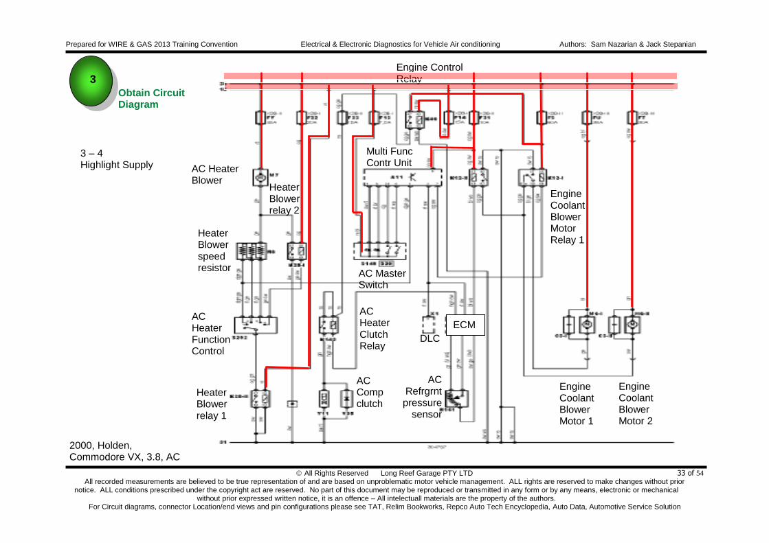
Obtain Circuit Diagram
3
Prepared for WIRE & GAS 2013 Training Convention Electrical & Electronic Diagnostics for Vehicle Air conditioning Authors: Sam Nazarian & Jack Stepanian
All Rights Reserved Long Reef Garage PTY LTD All recorded measurements are believed to be true representation of and are based on unproblematic motor vehicle management. ALL rights are reserved to make changes without prior
notice. ALL conditions prescribed under the copyright act are reserved. No part of this document may be reproduced or transmitted in any form or by any means, electronic or mechanical without prior expressed written notice, it is an offence – All intelectuall materials are the property of the authors.
For Circuit diagrams, connector Location/end views and pin configurations please see TAT, Relim Bookworks, Repco Auto Tech Encyclopedia, Auto Data, Automotive Service Solution
33 of 54
AC Heater Blower
Heater Blower speed resistor
AC Heater Function Control
AC Comp clutch
AC Heater Clutch Relay
DLC
AC Refrgrnt pressure
sensor
Engine Coolant Blower Motor 1
Engine Coolant Blower Motor 2
Multi Func Contr Unit
Engine Control Relay
AC Master Switch
Engine Coolant Blower Motor Relay 1
3 – 4 Highlight Supply
ECM
Heater Blower relay 2
Heater Blower relay 1
2000, Holden, Commodore VX, 3.8, AC
Obtain Circuit Diagram
3
Prepared for WIRE & GAS 2013 Training Convention Electrical & Electronic Diagnostics for Vehicle Air conditioning Authors: Sam Nazarian & Jack Stepanian
All Rights Reserved Long Reef Garage PTY LTD All recorded measurements are believed to be true representation of and are based on unproblematic motor vehicle management. ALL rights are reserved to make changes without prior
notice. ALL conditions prescribed under the copyright act are reserved. No part of this document may be reproduced or transmitted in any form or by any means, electronic or mechanical without prior expressed written notice, it is an offence – All intelectuall materials are the property of the authors.
For Circuit diagrams, connector Location/end views and pin configurations please see TAT, Relim Bookworks, Repco Auto Tech Encyclopedia, Auto Data, Automotive Service Solution
34 of 54
AC Heater Blower
Heater Blower speed resistor
AC Heater Function Control
AC Comp clutch
AC Heater Clutch Relay
DLC
AC Refrgrnt pressure
sensor
Engine Coolant Blower Motor 1
Engine Coolant Blower Motor 2
Multi Func Contr Unit
Engine Control Relay
AC Master Switch
Engine Coolant Blower Motor Relay 1
3 – 5 Highlight Grounds
ECM
Heater Blower relay 2
Heater Blower relay 1
2000, Holden, Commodore VX, 3.8, AC
Obtain Circuit Diagram
3

Prepared for WIRE & GAS 2013 Training Convention Electrical & Electronic Diagnostics for Vehicle Air conditioning Authors: Sam Nazarian & Jack Stepanian
All Rights Reserved Long Reef Garage PTY LTD All recorded measurements are believed to be true representation of and are based on unproblematic motor vehicle management. ALL rights are reserved to make changes without prior
notice. ALL conditions prescribed under the copyright act are reserved. No part of this document may be reproduced or transmitted in any form or by any means, electronic or mechanical without prior expressed written notice, it is an offence – All intelectuall materials are the property of the authors.
For Circuit diagrams, connector Location/end views and pin configurations please see TAT, Relim Bookworks, Repco Auto Tech Encyclopedia, Auto Data, Automotive Service Solution
35 of 54
AC Heater Blower
Heater Blower speed resistor
AC Heater Function Control
AC Comp clutch
AC Heater Clutch Relay
DLC
AC Refrgrnt pressure
sensor
Engine Coolant Blower Motor 1
Engine Coolant Blower Motor 2
Multi Func Contr Unit
Engine Control Relay
AC Master Switch
Engine Coolant Blower Motor Relay 1
3 – 5 Scenario 1 Clutch does not cut in. In order to identify component that may be the cause of symptom! One MUST consider the conditions that need to be met so that the system works properly. So, let’s assume that the compressor is NOT cutting in! And let’s assume that we do have good grounds and good supplies as highlighted.
ECM
Heater Blower relay 2
Heater Blower relay 1
2000, Holden, Commodore VX, 3.8, AC
Obtain Circuit Diagram
3

Prepared for WIRE & GAS 2013 Training Convention Electrical & Electronic Diagnostics for Vehicle Air conditioning Authors: Sam Nazarian & Jack Stepanian
All Rights Reserved Long Reef Garage PTY LTD All recorded measurements are believed to be true representation of and are based on unproblematic motor vehicle management. ALL rights are reserved to make changes without prior
notice. ALL conditions prescribed under the copyright act are reserved. No part of this document may be reproduced or transmitted in any form or by any means, electronic or mechanical without prior expressed written notice, it is an offence – All intelectuall materials are the property of the authors.
For Circuit diagrams, connector Location/end views and pin configurations please see TAT, Relim Bookworks, Repco Auto Tech Encyclopedia, Auto Data, Automotive Service Solution
36 of 54
AC Heater Blower
Heater Blower speed resistor
AC Heater Function Control
AC Comp clutch
AC Heater Clutch Relay
DLC
AC Refrgrnt pressure
sensor
Engine Coolant Blower Motor 1
Engine Coolant Blower Motor 2
Multi Func Contr Unit
Engine Control Relay
AC Master Switch
Engine Coolant Blower Motor Relay 1
3 – 6 Scenario 1 Clutch does not cut in. As ignition switch is turned to the position one (ignition ON) the heater blower relay will become energized and pull the contacts in – and by doing so the relay now provides ground potential to the AC heater function control
ECM
Heater Blower relay 2
Heater Blower relay 1
2000, Holden, Commodore VX, 3.8, AC
Obtain Circuit Diagram
3

Prepared for WIRE & GAS 2013 Training Convention Electrical & Electronic Diagnostics for Vehicle Air conditioning Authors: Sam Nazarian & Jack Stepanian
All Rights Reserved Long Reef Garage PTY LTD All recorded measurements are believed to be true representation of and are based on unproblematic motor vehicle management. ALL rights are reserved to make changes without prior
notice. ALL conditions prescribed under the copyright act are reserved. No part of this document may be reproduced or transmitted in any form or by any means, electronic or mechanical without prior expressed written notice, it is an offence – All intelectuall materials are the property of the authors.
For Circuit diagrams, connector Location/end views and pin configurations please see TAT, Relim Bookworks, Repco Auto Tech Encyclopedia, Auto Data, Automotive Service Solution
37 of 54
AC Heater Blower
Heater Blower speed resistor
AC Heater Function Control
AC Comp clutch
AC Heater Clutch Relay
DLC
AC Refrgrnt pressure
sensor
Engine Coolant Blower Motor 1
Engine Coolant Blower Motor 2
Multi Func Contr Unit
Engine Control Relay
AC Master Switch
Engine Coolant Blower Motor Relay 1
3 – 7 Scenario 1 Clutch does not cut in. However, AC system will NOT work until the AC heater function control is turned ON to have the heater blower operating! Indeed by doing so, all positions of AC heater function control (naturally other than off position) will provide near zero volts to the Multi-Function Control unit. (pin 3)
ECM
Heater Blower relay 2
Heater Blower relay 1
2000, Holden, Commodore VX, 3.8, AC
Obtain Circuit Diagram
3

Prepared for WIRE & GAS 2013 Training Convention Electrical & Electronic Diagnostics for Vehicle Air conditioning Authors: Sam Nazarian & Jack Stepanian
All Rights Reserved Long Reef Garage PTY LTD All recorded measurements are believed to be true representation of and are based on unproblematic motor vehicle management. ALL rights are reserved to make changes without prior
notice. ALL conditions prescribed under the copyright act are reserved. No part of this document may be reproduced or transmitted in any form or by any means, electronic or mechanical without prior expressed written notice, it is an offence – All intelectuall materials are the property of the authors.
For Circuit diagrams, connector Location/end views and pin configurations please see TAT, Relim Bookworks, Repco Auto Tech Encyclopedia, Auto Data, Automotive Service Solution
38 of 54
AC Heater Blower
Heater Blower speed resistor
AC Heater Function Control
AC Comp clutch
AC Heater Clutch Relay
DLC
AC Refrgrnt pressure
sensor
Engine Coolant Blower Motor 1
Engine Coolant Blower Motor 2
Multi Func Contr Unit
Engine Control Relay
AC Master Switch
Engine Coolant Blower Motor Relay 1
3 – 8 Scenario 1 Clutch does not cut in. Having the blower fan ON will only blow ‘HOT AIR’. And in order to activate the compressor clutch, the AC Master switch MUST be turned ON And by doing so, the AC Master Switch will now provide 12 volts signal supply to the Multi-Function control Unit (pin 9)
ECM
Heater Blower relay 2
Heater Blower relay 1
2000, Holden, Commodore VX, 3.8, AC
Obtain Circuit Diagram
3
Prepared for WIRE & GAS 2013 Training Convention Electrical & Electronic Diagnostics for Vehicle Air conditioning Authors: Sam Nazarian & Jack Stepanian
All Rights Reserved Long Reef Garage PTY LTD All recorded measurements are believed to be true representation of and are based on unproblematic motor vehicle management. ALL rights are reserved to make changes without prior
notice. ALL conditions prescribed under the copyright act are reserved. No part of this document may be reproduced or transmitted in any form or by any means, electronic or mechanical without prior expressed written notice, it is an offence – All intelectuall materials are the property of the authors.
For Circuit diagrams, connector Location/end views and pin configurations please see TAT, Relim Bookworks, Repco Auto Tech Encyclopedia, Auto Data, Automotive Service Solution
39 of 54
AC Heater Blower
Heater Blower speed resistor
AC Heater Function Control
AC Comp clutch
AC Heater Clutch Relay
DLC
AC Refrgrnt pressure
sensor
Engine Coolant Blower Motor 1
Engine Coolant Blower Motor 2
Multi Func Contr Unit
Engine Control Relay
AC Master Switch
Engine Coolant Blower Motor Relay 1
3 – 9 Scenario 1 Clutch does not cut in. And should BOTH conditions be satisfied by the Multi-function Control Unit (12volts on pin 9 and 0 volts on pin 3) Then, the Multi-function Control Unit will put a serial data bus communication (via its pin 2) to Electronic Control Module informing it those conditions to apply the compressor clutch solenoid have been met. Same information is also available on DLC pin 9 (for scan tool interrogation)
ECM
Heater Blower relay 2
Heater Blower relay 1
2000, Holden, Commodore VX, 3.8, AC
Obtain Circuit Diagram
3

Prepared for WIRE & GAS 2013 Training Convention Electrical & Electronic Diagnostics for Vehicle Air conditioning Authors: Sam Nazarian & Jack Stepanian
All Rights Reserved Long Reef Garage PTY LTD All recorded measurements are believed to be true representation of and are based on unproblematic motor vehicle management. ALL rights are reserved to make changes without prior
notice. ALL conditions prescribed under the copyright act are reserved. No part of this document may be reproduced or transmitted in any form or by any means, electronic or mechanical without prior expressed written notice, it is an offence – All intelectuall materials are the property of the authors.
For Circuit diagrams, connector Location/end views and pin configurations please see TAT, Relim Bookworks, Repco Auto Tech Encyclopedia, Auto Data, Automotive Service Solution
40 of 54
AC Heater Blower
Heater Blower speed resistor
AC Heater Function Control
AC Comp clutch
AC Heater Clutch Relay
DLC
AC Refrgrnt
pressure sensor
Engine Coolant Blower Motor 1
Engine Coolant Blower Motor 2
Multi Func Contr Unit
Engine Control Relay
AC Master Switch
Engine Coolant Blower Motor Relay 1
3 – 10 Scenario 1 Clutch does not cut in. ECM however is programmed NOT to apply the compressor clutch unless there is adequate R143A refrigerant present in the system Should it be higher or lower than threshold levels of the Feed Back information provided by the Air conditioning refrigerant pressure sensor, then the clutch will not be activated. Whilst there are many other ECM sensors that can affect the operation, the ACP sensors operation varying voltage information is paramount to the operation of AC clutch
ECM
Heater Blower relay 2
Heater Blower relay 1
2000, Holden, Commodore VX, 3.8, AC
Obtain Circuit Diagram
3

Prepared for WIRE & GAS 2013 Training Convention Electrical & Electronic Diagnostics for Vehicle Air conditioning Authors: Sam Nazarian & Jack Stepanian
All Rights Reserved Long Reef Garage PTY LTD All recorded measurements are believed to be true representation of and are based on unproblematic motor vehicle management. ALL rights are reserved to make changes without prior
notice. ALL conditions prescribed under the copyright act are reserved. No part of this document may be reproduced or transmitted in any form or by any means, electronic or mechanical without prior expressed written notice, it is an offence – All intelectuall materials are the property of the authors.
For Circuit diagrams, connector Location/end views and pin configurations please see TAT, Relim Bookworks, Repco Auto Tech Encyclopedia, Auto Data, Automotive Service Solution
41 of 54
AC Heater Blower
Heater Blower speed resistor
AC Heater Function Control
AC Comp clutch
AC Heater Clutch Relay
DLC
AC Refrgrnt pressure
sensor
Engine Coolant Blower Motor 1
Engine Coolant Blower Motor 2
Multi Func Contr Unit
Engine Control Relay
AC Master Switch
Engine Coolant Blower Motor Relay 1
3 – 11 Scenario 1 Clutch does not cut in. And should the ECM be satisfied by the operation voltage range of 1.8volts and 4.5volts, ECM will then provide an earth return path to the coil of the relay (will ground the relay)
ECM
Heater Blower relay 2
Heater Blower relay 1
2000, Holden, Commodore VX, 3.8, AC
Obtain Circuit Diagram
3

Prepared for WIRE & GAS 2013 Training Convention Electrical & Electronic Diagnostics for Vehicle Air conditioning Authors: Sam Nazarian & Jack Stepanian
All Rights Reserved Long Reef Garage PTY LTD All recorded measurements are believed to be true representation of and are based on unproblematic motor vehicle management. ALL rights are reserved to make changes without prior
notice. ALL conditions prescribed under the copyright act are reserved. No part of this document may be reproduced or transmitted in any form or by any means, electronic or mechanical without prior expressed written notice, it is an offence – All intelectuall materials are the property of the authors.
For Circuit diagrams, connector Location/end views and pin configurations please see TAT, Relim Bookworks, Repco Auto Tech Encyclopedia, Auto Data, Automotive Service Solution
42 of 54
AC Heater Blower
Heater Blower speed resistor
AC Heater Function Control
AC Comp clutch
AC Heater Clutch Relay
DLC
AC Refrgrnt pressure
sensor
Engine Coolant Blower Motor 1
Engine Coolant Blower Motor 2
Multi Func Contr Unit
Engine Control Relay
AC Master Switch
Engine Coolant Blower Motor Relay 1
3 – 12 Scenario 1 Clutch does not cut in. And as the ignition switch is turned ON [position one - ignition ON) the relay will be triggered and the grounding path provided by the ECM’s earth will enable the relay to be pulled in. And by doing so, the compressor clutch solenoid will now be energized and turned on.
ECM
Heater Blower relay 2
Heater Blower relay 1
2000, Holden, Commodore VX, 3.8, AC
Obtain Circuit Diagram
3

Prepared for WIRE & GAS 2013 Training Convention Electrical & Electronic Diagnostics for Vehicle Air conditioning Authors: Sam Nazarian & Jack Stepanian
All Rights Reserved Long Reef Garage PTY LTD All recorded measurements are believed to be true representation of and are based on unproblematic motor vehicle management. ALL rights are reserved to make changes without prior
notice. ALL conditions prescribed under the copyright act are reserved. No part of this document may be reproduced or transmitted in any form or by any means, electronic or mechanical without prior expressed written notice, it is an offence – All intelectuall materials are the property of the authors.
For Circuit diagrams, connector Location/end views and pin configurations please see TAT, Relim Bookworks, Repco Auto Tech Encyclopedia, Auto Data, Automotive Service Solution
43 of 54
AC Heater Blower
Heater Blower speed resistor
AC Heater Function Control
AC Compressor clutch
AC Heater Clutch Relay
DLC
AC Refrgrnt pressure
sensor
Engine Coolant Blower Motor 1
Engine Coolant Blower Motor 2
Multi Func Contr Unit
Engine Control Relay
AC Master Switch
Engine Coolant Blower Motor Relay 1
3 – 13 Scenario 1 Clutch does not cut in. Observe High pressure manifold pressure either by using an A - Oscilloscope (waveform) or B - Displayed in KPA and varying voltage in data list on the Scan tool ECM
Heater Blower relay 2
Heater Blower relay 1
2000, Holden, Commodore VX, 3.8, AC
Obtain Circuit Diagram
3
500milli volt / div 40 sec / div
As AC is turned ON, pressure builds up
1Amp / div 1 sec / div
Switching AC On & OFF
Built up of AC Pressure can be simulated
with the use of 5Killo Ohm variable resistor

Prepared for WIRE & GAS 2013 Training Convention Electrical & Electronic Diagnostics for Vehicle Air conditioning Authors: Sam Nazarian & Jack Stepanian
All Rights Reserved Long Reef Garage PTY LTD All recorded measurements are believed to be true representation of and are based on unproblematic motor vehicle management. ALL rights are reserved to make changes without prior
notice. ALL conditions prescribed under the copyright act are reserved. No part of this document may be reproduced or transmitted in any form or by any means, electronic or mechanical without prior expressed written notice, it is an offence – All intelectuall materials are the property of the authors.
For Circuit diagrams, connector Location/end views and pin configurations please see TAT, Relim Bookworks, Repco Auto Tech Encyclopedia, Auto Data, Automotive Service Solution
44 of 54
AC Heater Blower
Heater Blower speed resistor
AC Heater Function Control
AC Compressor clutch
AC Heater Clutch Relay
DLC
AC Refrgrnt pressure
sensor
Engine Coolant Blower Motor 1
Engine Coolant Blower Motor 2
Multi Func Contr Unit
Engine Control Relay
AC Master Switch
Engine Coolant Blower Motor Relay 1
3 – 14 Scenario 1 Clutch does not cut in. Current flowing through the AC compressor clutch can be measured by placing 0. Ohm Ceramic 5 Watt resistor and note the voltage drop across the resistor (which is proportional to current flow)
ECM
Heater Blower relay 2
Heater Blower relay 1
2000, Holden, Commodore VX, 3.8, AC
Obtain Circuit Diagram
3
1Amp / div 1 sec / div
Switching AC On & OFF

Prepared for WIRE & GAS 2013 Training Convention Electrical & Electronic Diagnostics for Vehicle Air conditioning Authors: Sam Nazarian & Jack Stepanian
All Rights Reserved Long Reef Garage PTY LTD All recorded measurements are believed to be true representation of and are based on unproblematic motor vehicle management. ALL rights are reserved to make changes without prior
notice. ALL conditions prescribed under the copyright act are reserved. No part of this document may be reproduced or transmitted in any form or by any means, electronic or mechanical without prior expressed written notice, it is an offence – All intelectuall materials are the property of the authors.
For Circuit diagrams, connector Location/end views and pin configurations please see TAT, Relim Bookworks, Repco Auto Tech Encyclopedia, Auto Data, Automotive Service Solution
45 of 54
Scenario 2 Should this component fail! What will the symptom be!
Obtain Circuit Diagram
3
3 – 15
2005, Holden, Commodore VZ, 3.6, DLC

Prepared for WIRE & GAS 2013 Training Convention Electrical & Electronic Diagnostics for Vehicle Air conditioning Authors: Sam Nazarian & Jack Stepanian
All Rights Reserved Long Reef Garage PTY LTD All recorded measurements are believed to be true representation of and are based on unproblematic motor vehicle management. ALL rights are reserved to make changes without prior
notice. ALL conditions prescribed under the copyright act are reserved. No part of this document may be reproduced or transmitted in any form or by any means, electronic or mechanical without prior expressed written notice, it is an offence – All intelectuall materials are the property of the authors.
For Circuit diagrams, connector Location/end views and pin configurations please see TAT, Relim Bookworks, Repco Auto Tech Encyclopedia, Auto Data, Automotive Service Solution
46 of 54
AC Control Unit
IGN main relay
Side lamp relay
Eng CLT relay
AC Comp clutch relay
AC Comp clutch solenoid
Engine coolant blower motor
Engine coolant blower motor relay `2 and 1
Multi function control module
Inst Panel
AC SUN light
ACP
ECT
Interface module
Heater Blowerrelay
AC Heater BlowerMotor
Mix Flap
AC Heater Blower Motor control module
Heated rear window relay
In Car
Temp sens
Out Side Temp sens
Evap Temp sens
AC Air Mix
Obtain Circuit Diagram
3
3 – 16 Identify and label each component
2005, Holden, Commodore VZ, 3.6, DLC
ECM
Scenario 2

Prepared for WIRE & GAS 2013 Training Convention Electrical & Electronic Diagnostics for Vehicle Air conditioning Authors: Sam Nazarian & Jack Stepanian
All Rights Reserved Long Reef Garage PTY LTD All recorded measurements are believed to be true representation of and are based on unproblematic motor vehicle management. ALL rights are reserved to make changes without prior
notice. ALL conditions prescribed under the copyright act are reserved. No part of this document may be reproduced or transmitted in any form or by any means, electronic or mechanical without prior expressed written notice, it is an offence – All intelectuall materials are the property of the authors.
For Circuit diagrams, connector Location/end views and pin configurations please see TAT, Relim Bookworks, Repco Auto Tech Encyclopedia, Auto Data, Automotive Service Solution
47 of 54
AC Control Unit
IGN main relay
Side Park lamp relay
Eng CLT relay
AC Comp clutch relay
AC Comp clutch solenoid
Engine coolant blower motor
Engine coolant blower motor relay `2 and 1
Multi function control module
Inst Panel
AC SUN light
ACP
ECT
Interface module
Heater Blowerrelay
AC Heater BlowerMotor
Mix Flap
AC Heater Blower Motor control module
Heated rear window relay
In Car
Temp sens
Out Side
Temp sens
Evap Temp sens
AC Air Mix
2005, Holden, Commodore VZ, 3.6, DLC
Obtain Circuit Diagram
3
3 –17 Should this component fail! What will the symptom be!
ECM
Scenario 2

Prepared for WIRE & GAS 2013 Training Convention Electrical & Electronic Diagnostics for Vehicle Air conditioning Authors: Sam Nazarian & Jack Stepanian
All Rights Reserved Long Reef Garage PTY LTD All recorded measurements are believed to be true representation of and are based on unproblematic motor vehicle management. ALL rights are reserved to make changes without prior
notice. ALL conditions prescribed under the copyright act are reserved. No part of this document may be reproduced or transmitted in any form or by any means, electronic or mechanical without prior expressed written notice, it is an offence – All intelectuall materials are the property of the authors.
For Circuit diagrams, connector Location/end views and pin configurations please see TAT, Relim Bookworks, Repco Auto Tech Encyclopedia, Auto Data, Automotive Service Solution
48 of 54
Scenario 3 AC Heater Blower Motor Inoperative Pulse Width Modulated (PWM) amplifier circuit(s) Identify main components
Obtain Circuit Diagram
3
3 – 18
AC Control Module
AC Heater Blower Control module
AC Heater Blower Motor
98, BMW/3 Series (E36), 2.5 323i, wiring diagram, AC control)

Prepared for WIRE & GAS 2013 Training Convention Electrical & Electronic Diagnostics for Vehicle Air conditioning Authors: Sam Nazarian & Jack Stepanian
All Rights Reserved Long Reef Garage PTY LTD All recorded measurements are believed to be true representation of and are based on unproblematic motor vehicle management. ALL rights are reserved to make changes without prior
notice. ALL conditions prescribed under the copyright act are reserved. No part of this document may be reproduced or transmitted in any form or by any means, electronic or mechanical without prior expressed written notice, it is an offence – All intelectuall materials are the property of the authors.
For Circuit diagrams, connector Location/end views and pin configurations please see TAT, Relim Bookworks, Repco Auto Tech Encyclopedia, Auto Data, Automotive Service Solution
49 of 54
Obtain Circuit Diagram
3
AC Control Module
AC Heater Blower Control module
AC Heater Blower Motor
Scenario 3 AC Heater Blower Motor Inoperative Pulse Width Modulated (PWM) amplifier circuit(s) Identify main components
3 – 19
2 volt / div 1 sec / div
2 volt / div 1 sec / div
98, BMW/3 Series (E36), 2.5 323i, wiring diagram, AC control)
Prepared for WIRE & GAS 2013 Training Convention Electrical & Electronic Diagnostics for Vehicle Air conditioning Authors: Sam Nazarian & Jack Stepanian
All Rights Reserved Long Reef Garage PTY LTD All recorded measurements are believed to be true representation of and are based on unproblematic motor vehicle management. ALL rights are reserved to make changes without prior
notice. ALL conditions prescribed under the copyright act are reserved. No part of this document may be reproduced or transmitted in any form or by any means, electronic or mechanical without prior expressed written notice, it is an offence – All intelectuall materials are the property of the authors.
For Circuit diagrams, connector Location/end views and pin configurations please see TAT, Relim Bookworks, Repco Auto Tech Encyclopedia, Auto Data, Automotive Service Solution
50 of 54
Scenario 4 AC Engine Blower Motor Inoperative Pulse Width Modulated (PWM) amplifier circuit(s) Identify main components
ABS
ECM
ECT Switch
AC Heater Blower Motor
Engine Collant Blower Motor
ACP
ECT
AC Control unit
Digital Multifunction Display (Gateway)
Obtain Circuit Diagram
3
03, Citroen, C3 I/II/First class, 1.6/AC, MY-2005 (auto temp control)
3 – 20
Prepared for WIRE & GAS 2013 Training Convention Electrical & Electronic Diagnostics for Vehicle Air conditioning Authors: Sam Nazarian & Jack Stepanian
All Rights Reserved Long Reef Garage PTY LTD All recorded measurements are believed to be true representation of and are based on unproblematic motor vehicle management. ALL rights are reserved to make changes without prior
notice. ALL conditions prescribed under the copyright act are reserved. No part of this document may be reproduced or transmitted in any form or by any means, electronic or mechanical without prior expressed written notice, it is an offence – All intelectuall materials are the property of the authors.
For Circuit diagrams, connector Location/end views and pin configurations please see TAT, Relim Bookworks, Repco Auto Tech Encyclopedia, Auto Data, Automotive Service Solution
51 of 54
ABS
ECM
ECT Switch
AC Heater Blower Motor
Engine Collant Blower Motor
ACP
ECT
AC Control unit
2
3 4
1
Obtain Circuit Diagram
3
2 volt / div 2 milli sec / div
2 volt / div 2 milli sec / div
Scenario 4 AC Engine Blower Motor Inoperative Pulse Width Modulated (PWM) amplifier circuit(s) Identify main components
03, Citroen, C3 I/II/First class, 1.6/AC, MY-2005 (auto temp control)
3 – 21

Prepared for WIRE & GAS 2013 Training Convention Electrical & Electronic Diagnostics for Vehicle Air conditioning Authors: Sam Nazarian & Jack Stepanian
All Rights Reserved Long Reef Garage PTY LTD All recorded measurements are believed to be true representation of and are based on unproblematic motor vehicle management. ALL rights are reserved to make changes without prior
notice. ALL conditions prescribed under the copyright act are reserved. No part of this document may be reproduced or transmitted in any form or by any means, electronic or mechanical without prior expressed written notice, it is an offence – All intelectuall materials are the property of the authors.
For Circuit diagrams, connector Location/end views and pin configurations please see TAT, Relim Bookworks, Repco Auto Tech Encyclopedia, Auto Data, Automotive Service Solution
52 of 54
Abbreviation, acronyms and references: Abbreviations: CAN BUS – Controlled Area Network Bidirectional Universal System BEM – Body Electrical Module PCM – Power Control Module HIM – Heater and air conditioning Integrated Module SRS – Supplementary Restraint System INS – Instrument Cluster Panel ICC – Interior Command Centre DMM – Digital Multi meter OSC – Oscilloscope ICU – Immobilizer Control Unit YRS – Yaw Rate Sensor SAS – Steering Angle sensor APPs – Accelerator Pedal Position sensor TPS – Throttle position Sensor ECTS – Engine coolant temperature Sensor CKPS – Crankshaft position Sensor Web sites: (these are only a few of sites visited)
References:
http://www.chevyavalanchefanclub.com/cafcna/index.php?topic=26444.0;wap2
http://ikwilthepiratebay.org/thepiratebay.se/torrent/3591423/GM_Techline_eSI
http://forums.justcommodores.com.au/ve-holden-commodore-2006-2013/194506-ve-sv6-ute-work-shop-manual.html
http://aurorah.proboards.com/index.cgi?board=Gen&action=print&thread=16952
http://www.ebay.com.au/itm/GM-CHEVY-ESI-ELECTRONIC-SERVICE-INFO-SYSTEM-MANUAL-/230605688505
http://www.ebay.com.au/itm/GM-CHEVY-ESI-ELECTRONIC-SERVICE-INFO-SYSTEM-MANUAL-/230605688505
DLC - Diagnostic Link Connector TCM - Transmission Control Module PNL - Park Neutral Lever Auto Unit Ins - Instrument panel NAV - Navigation Park contr - Parking control TPMS - Tyre pressure monitoring system ABS - Anti Lock Braking SAS - Steering Angle Sensor SRS - Supplementary Restraint System MFCU - Multi-Function Control Unit (often referred to as BCM) BCM - Body control Module)

Prepared for WIRE & GAS 2013 Training Convention Electrical & Electronic Diagnostics for Vehicle Air conditioning Authors: Sam Nazarian & Jack Stepanian
All Rights Reserved Long Reef Garage PTY LTD All recorded measurements are believed to be true representation of and are based on unproblematic motor vehicle management. ALL rights are reserved to make changes without prior
notice. ALL conditions prescribed under the copyright act are reserved. No part of this document may be reproduced or transmitted in any form or by any means, electronic or mechanical without prior expressed written notice, it is an offence – All intelectuall materials are the property of the authors.
For Circuit diagrams, connector Location/end views and pin configurations please see TAT, Relim Bookworks, Repco Auto Tech Encyclopedia, Auto Data, Automotive Service Solution
53 of 54
CARS
SYMPTOMS
REMEDIES

Prepared for WIRE & GAS 2013 Training Convention Electrical & Electronic Diagnostics for Vehicle Air conditioning Authors: Sam Nazarian & Jack Stepanian
All Rights Reserved Long Reef Garage PTY LTD All recorded measurements are believed to be true representation of and are based on unproblematic motor vehicle management. ALL rights are reserved to make changes without prior
notice. ALL conditions prescribed under the copyright act are reserved. No part of this document may be reproduced or transmitted in any form or by any means, electronic or mechanical without prior expressed written notice, it is an offence – All intelectuall materials are the property of the authors.
For Circuit diagrams, connector Location/end views and pin configurations please see TAT, Relim Bookworks, Repco Auto Tech Encyclopedia, Auto Data, Automotive Service Solution
54 of 54