electric roller garage door fitting instructions€¦ · electric roller garage door components 1...
TRANSCRIPT
�
Tota
l Hei
ght
Gro
und
Hei
ght
Hea
droo
m
Drive Through Height
Drive Through Width
Over Guide Width
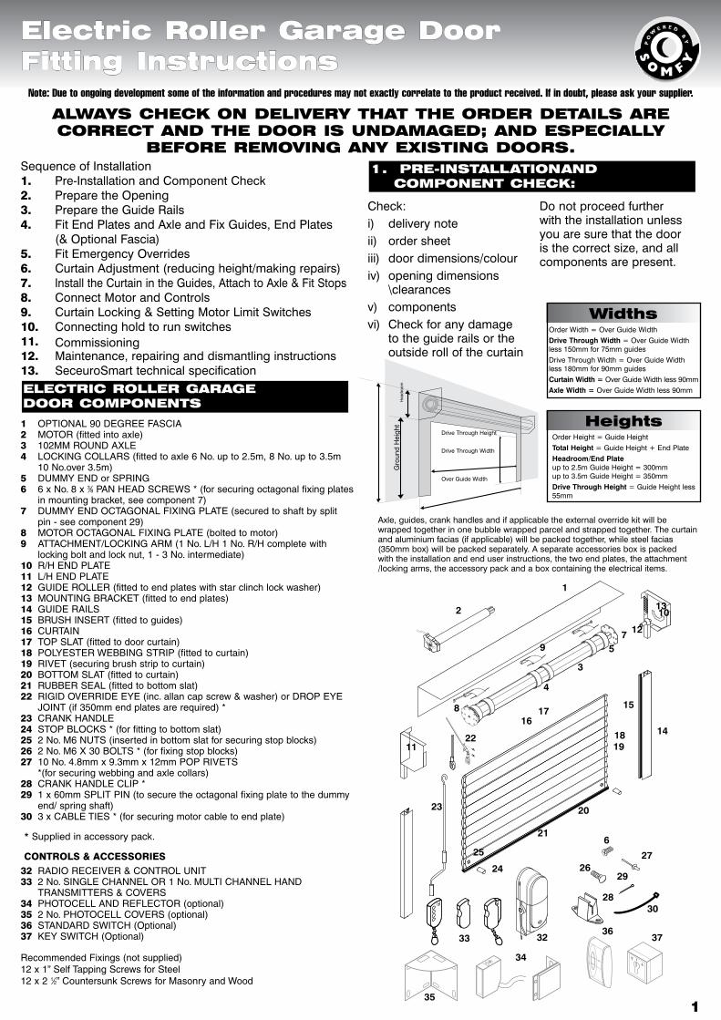
ELECTRIC ROLLER GARAGE DOOR COMPONENTS
1 OPTIONAL90DEGREEFASCIA2 MOTOR(fittedintoaxle)3 102MMROUNDAXLE4 LOCKINGCOLLARS(fittedtoaxle6No.upto2.5m,8No.upto3.5m
10No.over3.5m)5 DUMMYENDorSPRING6 6xNo.8x3⁄8PANHEADSCREWS*(forsecuringoctagonalfixingplates inmountingbracket,seecomponent7)7 DUMMYENDOCTAGONALFIXINGPLATE(securedtoshaftbysplit
pin-seecomponent29)8 MOTOROCTAGONALFIXINGPLATE(boltedtomotor)9 ATTACHMENT/LOCKINGARM(1No.L/H1No.R/Hcompletewith
lockingboltandlocknut,1-3No.intermediate)10 R/HENDPLATE11 L/HENDPLATE12 GUIDEROLLER(fittedtoendplateswithstarclinchlockwasher)13 MOUNTINGBRACKET(fittedtoendplates)14 GUIDERAILS15 BRUSHINSERT(fittedtoguides)16 CURTAIN17 TOPSLAT(fittedtodoorcurtain)18 POLYESTERWEBBINGSTRIP(fittedtocurtain)19 RIVET(securingbrushstriptocurtain)20 BOTTOMSLAT(fittedtocurtain)21 RUBBERSEAL(fittedtobottomslat)22 RIGIDOVERRIDEEYE(inc.allancapscrew&washer)orDROPEYE
JOINT(if350mmendplatesarerequired)*23 CRANKHANDLE24 STOPBLOCKS*(forfittingtobottomslat)25 2No.M6NUTS(insertedinbottomslatforsecuringstopblocks)26 2No.M6X30BOLTS*(forfixingstopblocks)27 10No.4.8mmx9.3mmx12mmPOPRIVETS
*(forsecuringwebbingandaxlecollars)28 CRANKHANDLECLIP*29 1x60mmSPLITPIN(tosecuretheoctagonalfixingplatetothedummy
end/springshaft)30 3xCABLETIES*(forsecuringmotorcabletoendplate)
* Supplied in accessory pack.
CONTROLS&ACCESSORIES32 RADIORECEIVER&CONTROLUNIT33 2No.SINGLECHANNELOR1No.MULTICHANNELHAND
TRANSMITTERS&COVERS34 PHOTOCELLANDREFLECTOR(optional)35 2No.PHOTOCELLCOVERS(optional)36 STANDARDSWITCH(Optional)37 KEYSWITCH(Optional)
RecommendedFixings(notsupplied)12x1”SelfTappingScrewsforSteel12x21⁄2”CountersunkScrewsforMasonryandWood
1. PRE-INSTALLATION AND COMPONENT ChECk:
Sequence of Installation1. Pre-Installation and Component Check2. Prepare the Opening3. Prepare the Guide Rails4. Fit End Plates and Axle and Fix Guides, End Plates
(& Optional Fascia)5. Fit Emergency Overrides6. Curtain Adjustment (reducing height/making repairs)7. Install the Curtain in the Guides, Attach to Axle & Fit Stops8. Connect Motor and Controls9. Curtain Locking & Setting Motor Limit Switches10. Connecting hold to run switches11. Commissioning12. Maintenance, repairing and dismantling instructions13. SeceuroSmart technical specification
Note: Due to ongoing development some of the information and procedures may not exactly correlate to the product received. If in doubt, please ask your supplier.
Electric Roller Garage Door Fitting Instructions
ALwAyS ChECk ON DELIvERy ThAT ThE ORDER DETAILS ARE CORRECT AND ThE DOOR IS uNDAMAGED; AND ESPECIALLy
bEFORE REMOvING ANy ExISTING DOORS.
Check:i) delivery noteii) order sheetiii) door dimensions/colouriv) opening dimensions
\clearancesv) componentsvi) Check for any damage
to the guide rails or the outside roll of the curtain
Do not proceed further with the installation unless you are sure that the door is the correct size, and all components are present.
widthsOrder Width = Over Guide Width Drive Through Width = Over Guide Width less 150mm for 75mm guidesDrive Through Width = Over Guide Width less 180mm for 90mm guidesCurtain Width = Over Guide Width less 90mmAxle Width = Over Guide Width less 90mm
heightsOrder Height = Guide HeightTotal Height = Guide Height + End PlateHeadroom/End Plate up to 2.5m Guide Height = 300mm up to 3.5m Guide Height = 350mmDrive Through Height = Guide Height less 55mm
Axle, guides, crank handles and if applicable the external override kit will be wrapped together in one bubble wrapped parcel and strapped together. The curtain and aluminium facias (if applicable) will be packed together, while steel facias (350mm box) will be packed separately. A separate accessories box is packed with the installation and end user instructions, the two end plates, the attachment /locking arms, the accessory pack and a box containing the electrical items.
1
2
4
3
8
11
13
14
9
1819
15
2023
24
25
21
12
10
75
6
28
29
2726
33
30
32
1617
22
35
34
3637
�
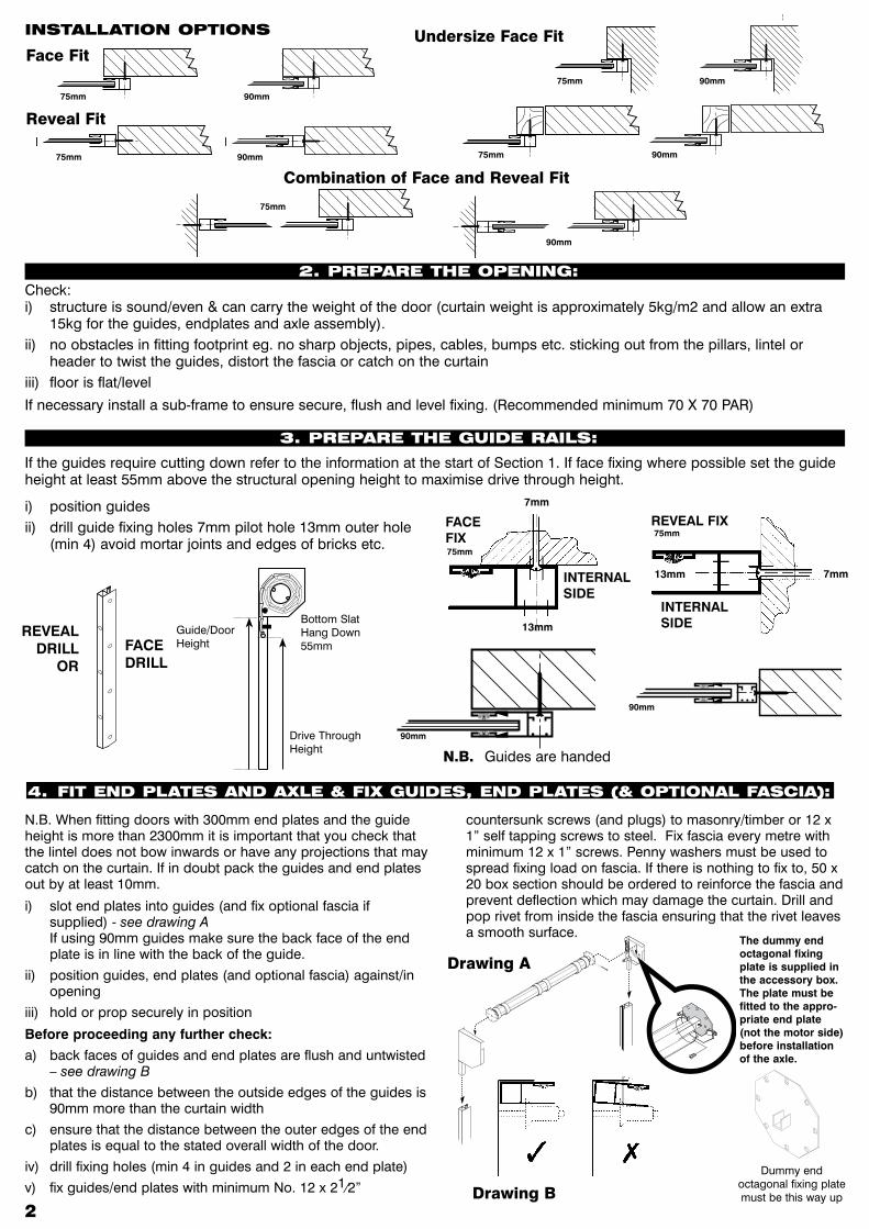
N.B. When fitting doors with 300mm end plates and the guide height is more than 2300mm it is important that you check that the lintel does not bow inwards or have any projections that may catch on the curtain. If in doubt pack the guides and end plates out by at least 10mm.
i) slot end plates into guides (and fix optional fascia if supplied) - see drawing A If using 90mm guides make sure the back face of the end plate is in line with the back of the guide.
ii) position guides, end plates (and optional fascia) against/in opening
iii) hold or prop securely in position
Before proceeding any further check:
a) back faces of guides and end plates are flush and untwisted – see drawing B
b) that the distance between the outside edges of the guides is 90mm more than the curtain width
c) ensure that the distance between the outer edges of the end plates is equal to the stated overall width of the door.
iv) drill fixing holes (min 4 in guides and 2 in each end plate)
v) fix guides/end plates with minimum No. 12 x 21⁄2”
countersunk screws (and plugs) to masonry/timber or 12 x 1” self tapping screws to steel. Fix fascia every metre with minimum 12 x 1” screws. Penny washers must be used to spread fixing load on fascia. If there is nothing to fix to, 50 x 20 box section should be ordered to reinforce the fascia and prevent deflection which may damage the curtain. Drill and pop rivet from inside the fascia ensuring that the rivet leaves a smooth surface.
�
INSTALLATION OPTIONS
Check:i) structure is sound/even & can carry the weight of the door (curtain weight is approximately 5kg/m2 and allow an extra
15kg for the guides, endplates and axle assembly).ii) no obstacles in fitting footprint eg. no sharp objects, pipes, cables, bumps etc. sticking out from the pillars, lintel or
header to twist the guides, distort the fascia or catch on the curtainiii) floor is flat/level
If necessary install a sub-frame to ensure secure, flush and level fixing. (Recommended minimum 70 X 70 PAR)
N.B. Guides are handed
If the guides require cutting down refer to the information at the start of Section 1. If face fixing where possible set the guide height at least 55mm above the structural opening height to maximise drive through height.
i) position guidesii) drill guide fixing holes 7mm pilot hole 13mm outer hole
(min 4) avoid mortar joints and edges of bricks etc.
4. FIT END PLATES AND AxLE & FIx GuIDES, END PLATES (& OPTIONAL FASCIA):
Close
Open
Bottom Slat Hang Down 55mm
Drive Through Height
Guide/Door Height
90mm90mm
RevealFit
75mm
75mm
CombinationofFaceandRevealFit
90mm
75mm
FaceFit
90mm
75mm
75mm
UndersizeFaceFit
90mm
DrawingA
DrawingB
Dummy end octagonal fixing plate must be this way up
FACE FIX
13mm
7mm
75mm
REVEAL FIX
INTERNAL SIDE
7mm13mm
75mm
The dummy end octagonal fixing plate is supplied in the accessory box. The plate must be fitted to the appro-priate end plate (not the motor side) before installation of the axle.
2. PREPARE ThE OPENING:
3. PREPARE ThE GuIDE RAILS:
FACE DRILL
REVEAL DRILL
OR
INTERNAL SIDE
90mm
90mm
�
5
�
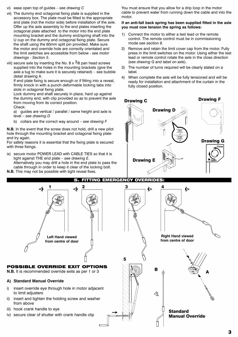
vi) ease open top of guides – see drawing Cvii) The dummy end octagonal fixing plate is supplied in the
accessory box. The plate must be fitted to the appropriate end plate (not the motor side) before installation of the axle. Offer up the axle assembly to the end plates inserting the octagonal plate attached to the motor into the end plate mounting bracket and the dummy end/spring shaft into the U cup on the dummy end octagonal fixing plate. Secure the shaft using the 60mm split pin provided. Make sure the motor and override hole are correctly orientated and the limit switches are accessible from below - see motor drawings - Section 5.
viii) secure axle by inserting the No. 8 x 3⁄8 pan head screws supplied into the holes in the mounting brackets (give the axle a tug to make sure it is securely retained) – see bubble detail drawing A. If end plate fixing is secure enough or if fitting into a reveal, firmly knock in with a punch deformable locking tabs into slots in octagonal fixing plate. Lock dummy end shaft securely in place, hard up against the dummy end, with clip provided so as to prevent the axle from moving from its correct position. Check:
a) guides are vertical / parallel / same height and axle is level – see drawing D
b) collars are the correct way around – see drawing F
N.B. In the event that the screw does not hold, drill a new pilot hole through the mounting bracket and octagonal fixing plate and try again. For safety reasons it is essential that the fixing plate is secured with three fixings.
ix) secure motor POWER LEAD with CABLE TIES so that it is tight against THE end plate – see drawing E. Alternatively you may drill a hole in the end plate to pass the cable through in order to keep it clear of the locking bolt.
N.B. This may not be possible with tight reveal fixes.
You must ensure that you allow for a drip loop in the motor cable to prevent water from running down the cable and into the motor.
If an anti-fall back spring has been supplied fitted in the axle you must now tension the spring as follows:
1) Connect the motor to either a test lead or the remote control. The remote control must be in commissioning mode see section 8.
2) Remove and retain the limit cover cap from the motor. Fully press in the limit switches on the motor. Using either the test lead or remote control rotate the axle in the close direction (see drawing G and label on axle).
3) The number of turns required will be clearly stated on a label.
4) When complete the axle will be fully tensioned and will be ready for installation and attachment of the curtain in the fully closed position.
1 2 3 4
Left Hand viewed from centre of door
Right Hand viewed from centre of door
POSSIbLE OvERRIDE ExIT OPTIONS N.B. It is recommended override exits as per 1 or 3
DrawingD
DrawingC
DrawingE
DrawingF
StandardManualOverride
A) Standard Manual Override
i) insert override eye through hole in motor adjacent to limit adjusters
ii) insert and tighten the holding screw and washer from above
iii) hook crank handle to eyeiv) secure clear of shutter with crank handle clip
A
DrawingG
5. FITTING EMERGENCy OvERRIDES:
B
�
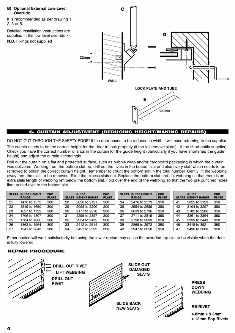
DO NOT CUT THROUGH THE SAFETY EDGE! If the door needs to be reduced in width it will need returning to the supplier.
The curtain needs to be the correct height for the door to lock properly (if too tall remove slat(s) - If too short notify supplier). Check you have the correct number of slats in the curtain for the guide height (particularly if you have shortened the guide height) and adjust the curtain accordingly.
Roll out the curtain on a flat and protected surface, such as bubble wrap and/or cardboard packaging in which the curtain was delivered. Working from the bottom slat up, drill out the rivets in the bottom slat and also every slat, which needs to be removed to obtain the correct curtain height. Remember to count the bottom slat in the total number. Gently lift the webbing away from the slats to be removed. Slide the excess slats out. Replace the bottom slat and cut webbing so that there is an extra slats length of webbing left below the bottom slat. Fold over the end of the webbing so that the two pre punched holes line up and rivet to the bottom slat.
D
SLIDE BACK NEW SLATS
SLIDE OUT DAMAGED
SLATS
PRESS DOWN WEBBING
RE-RIVET
4.8mm x 9.3mm x 12mm Pop Rivets
DRILL OUT RIVET
LIFT WEBBING
DRILL OUT RIVET
REPAIR PROCEDuRE
Either choice will work satisfactorily but using the lower option may cause the extruded top slat to be visible when the door is fully lowered.
WALL
22mm
CB) Optional External Low-Level Override
It is recommended as per drawing 1, 2, 3 or 5.
Detailed installation instructions are supplied in the low level override kit.N.B. Fixings not supplied
6. CuRTAIN ADjuSTMENT (REDuCING hEIGhT/MAkING REPAIRS)
21 1470 to 1572 30022 1549 to 1650 30023 1627 to 1729 30024 1706 to 1807 30025 1784 to 1886 30026 1863 to 1964 30027 1941 to 2043 300
SLATS GUIDEHEIGHT END RANGE PLATE
28 2020 to 2121 30029 2098 to 2200 30030 2177 to 2278 30031 2255 to 2357 30032 2334 to 2435 30033 2412 to 2514 30034 2491 to 2592 300
GUIDE ENDSLATS HEIGHTRANGE PLATE
34 2476 to 2579 35035 2554 to 2658 35036 2633 to 2736 35037 2711 to 2815 35038 2790 to 2893 35039 2868 to 2972 35040 2947 to 3050 350
SLATS GUIDEHEIGHT END RANGE PLATE
41 3025 to 3129 35042 3104 to 3207 35043 3182 to 3286 35044 3261 to 3364 35045 3339 to 3443 35046 3418 to 3521 35047 3496 to 3600 350
GUIDE ENDSLATS HEIGHTRANGE PLATE
500mm
LOCK PLATE AND TUBE
E
� �
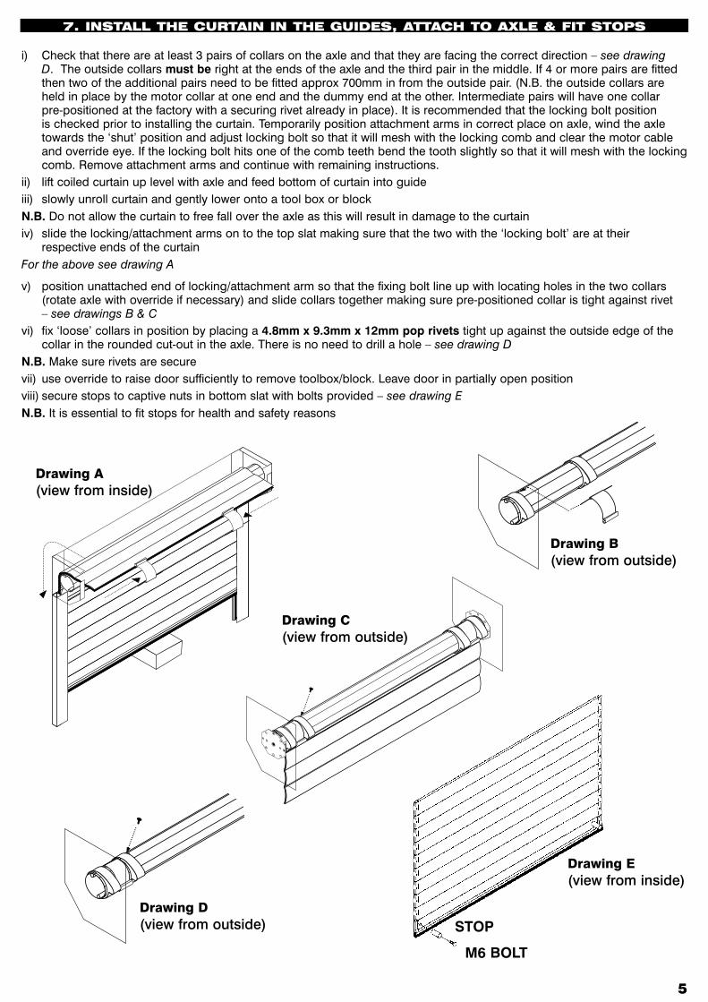
i) Check that there are at least 3 pairs of collars on the axle and that they are facing the correct direction – see drawing D. The outside collars must be right at the ends of the axle and the third pair in the middle. If 4 or more pairs are fitted then two of the additional pairs need to be fitted approx 700mm in from the outside pair. (N.B. the outside collars are held in place by the motor collar at one end and the dummy end at the other. Intermediate pairs will have one collar pre-positioned at the factory with a securing rivet already in place). It is recommended that the locking bolt position is checked prior to installing the curtain. Temporarily position attachment arms in correct place on axle, wind the axle towards the ‘shut’ position and adjust locking bolt so that it will mesh with the locking comb and clear the motor cable and override eye. If the locking bolt hits one of the comb teeth bend the tooth slightly so that it will mesh with the locking comb. Remove attachment arms and continue with remaining instructions.
ii) lift coiled curtain up level with axle and feed bottom of curtain into guideiii) slowly unroll curtain and gently lower onto a tool box or blockN.B. Do not allow the curtain to free fall over the axle as this will result in damage to the curtainiv) slide the locking/attachment arms on to the top slat making sure that the two with the ‘locking bolt’ are at their
respective ends of the curtainFor the above see drawing A
v) position unattached end of locking/attachment arm so that the fixing bolt line up with locating holes in the two collars (rotate axle with override if necessary) and slide collars together making sure pre-positioned collar is tight against rivet – see drawings B & C
vi) fix ‘loose’ collars in position by placing a 4.8mm x 9.3mm x 12mm pop rivets tight up against the outside edge of the collar in the rounded cut-out in the axle. There is no need to drill a hole – see drawing D
N.B. Make sure rivets are securevii) use override to raise door sufficiently to remove toolbox/block. Leave door in partially open positionviii) secure stops to captive nuts in bottom slat with bolts provided – see drawing EN.B. It is essential to fit stops for health and safety reasons
DrawingA(view from inside)
DrawingC(view from outside)
Close
Open
DrawingB(view from outside)
Close
Open
DrawingD(view from outside) STOP
M6 BOLT
DrawingE(view from inside)
7. INSTALL ThE CuRTAIN IN ThE GuIDES, ATTACh TO AxLE & FIT STOPS
�
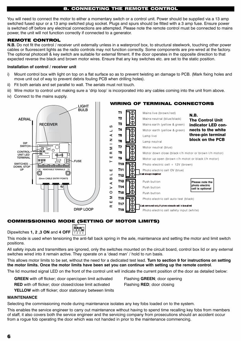
COMMISSIONING MODE (SETTING OF MOTOR LIMITS)
Dipswitches 1, 2 ,3 ON and 4 OFF
This mode is used when tensioning the anti-fall back spring in the axle, maintenance and setting the motor and limit switch positions.
All safety inputs and transmitters are ignored, only the switches mounted on the circuit board, control box lid or any external switches wired into it remain active. They operate on a ‘dead man’ / hold to run basis.
This allows motor limits to be set, without the need for a dedicated test lead. Turn to section 9 for instructions on setting the motor limits. Once the motor limits have been set you can continue with setting up the remote control.
The lid mounted signal LED on the front of the control unit will indicate the current position of the door as detailed below:
GREEN with off flicker; door open/open limit activated Flashing GREEN; door opening RED with off flicker; door closed/close limit activated Flashing RED; door closing YELLOW with off flicker; door stationary between limits
MAINTENANCE
Selecting the commissioning mode during maintenance isolates any key fobs loaded on to the system.
This enables the service engineer to carry out maintenance without having to spend time recalling key fobs from members of staff, it also covers both the service engineer and the servicing company from prosecutions should an accident occur from a rogue fob operating the door which was not handed in prior to the maintenance commencing.
You will need to connect the motor to either a momentary switch or a control unit. Power should be supplied via a 13 ampswitched fused spur or a 13 amp switched plug socket. Plugs and spurs should be fitted with a 3 amp fuse. Ensure power is switched off before any electrical connections are attempted. Please note the remote control must be connected to mains power, the unit will not function correctly if connected to a generator.
REMOTE CONTROLN.B. Do not fit the control / receiver unit externally unless in a waterproof box, to structural steelwork, touching other power cables or fluorescent lights as the radio controls may not function correctly. Some components are pre-wired at the factory. The optional photocell & key switch are suitable for external fitment. If the door operates in the opposite direction to that expected reverse the black and brown motor wires. Ensure that any key switches etc. are set to the static position.
Installation of control / receiver unit
i) Mount control box with light on top on a flat surface so as to prevent twisting an damage to PCB. (Mark fixing holes and move unit out of way to prevent debris fouling PCB when drilling holes).
ii) Fit both aerials and set parallel to wall. The aerials must not touch.iii) Wire motor to control unit making sure a ‘drip loop’ is incorporated into any cables coming into the unit from above.iv) Connect to the mains supply.
1 2 3 4
ON
AERIALRECEIVER
LIGHTBULB
DRIP LOOP
DIPSWITCH
CONTROLUNIT LEDTERMINAL
SWITCHES -DOWN, STOP
UP
20mm CABLE ENTRY POINTS
T18 REMOVABLE TERMINALS T1
RESET
RELAYS
FUSE
R E
M O
V A
B L
E
T
E R
M I
N A
L S
T1
T2
T3
T4
T5
T6
T7
T8
T9
T10
T11
T12
T13
T14
T15
T16
T17
T18
Mains l i ve (brow n/ red)
Mains neut ral (blue/ black)
Mains ear t h (yel low & green)
Mot or ear t h (yel low & green)
Lamp l i ve
Lamp neut ral
Mot or neut ral (blue)
Mot or dow n close (black r / h mot or or brow n l / h mot or )
Mot or up open (brow n r / h mot ot or black l / h mot or )
Photo electr ic cel l + 12V (brown)
Phot o elect r i c cel l OV (blue)
Push but t on
Push but t on
Push but t on
Phot o elect r i c cel l aut o t est (black)
Phot o elect r i c cel l safet y i nput (w hi t e)
Link alw ays requi red
Link removed on ly i f phot o elect r i c cel l i s i nst al l ed
wIRING OF TERMINAL CONNECTORS
N.B.TheControlUnitindicatorLEDcon-nectstothewhitethree-pinterminalblockonthePCB
Please note thephoto electric cell is optional
8. CONNECTING ThE REMOTE CONTROL

� �
wIRELESS SAFETy EDGEThe Safety Edge is fitted to the bottom of the door and is activated when the door starts to close. If it comes into contact with an object while the door is closing, it transmits a signal to the wall mounted control unit, the door will then stop and reopen a short distance.
The safety edge also works as a weather seal, designed to be pressed against the ground, to prevent false sensing and re-opening it is disabled within the last 50mm of door travel.
FITTING ThE bOTTOM SLAT TRANSMITTER1. Slide the bottom slat edge wire (protruding from the hole in the bottom slat) on to the two pronged connector on the
bottom slat transmitter board, ensuring that the wire passes through the rubber seal first.2. Attach the bottom slat transmitter to the bottom slat with the two self tapping screws provided (3mm drill bit), ensuring
that the flat side of the bottom slat transmitter is facing the guide and is as close to the guide as it can be without ever touching (maximumof10mmaway). Do not use a power operated screwdriver as it could distort and damage the printed circuit board in the bottom slat transmitter.
FITTING ThE MAGNET hOuSINGSPlease note if the garage door is being face fitted externally the magnets will need recessing into the surface you are fixing the door to. The magnets must not be mounted on the external exposed face of the guide rails if the garage door is externally fitted. Preparethesurfaceoftheguiderailbeforeattachingthemagnetholderbycleaningtherelevantareawiththewipeprovidedandthenallowtodry(if required remove the magnet from the housing).
Whentwodoorsarebeinginstalledsidebyside,nexttoeachotheryoumustavoidpositioningthetopmagnetsparalleltoeachother.Oneofthetopmagnetsmustbelocated20mmbelowtheothertopmagnet,thiswillpreventtheneighbouringmagnetfrominterferingwiththesystem.
1. When the curtain is fully raised (on the top limit) attach the top magnet (50mm below the bottom slat transmitter), with the flat edge facing the curtain and in line with the inner edge of the guide (as shown on diagram).
2. Attach the bottom magnet 200mm from the floor again ensuring the flat face is in line with the guide and facing the curtain.
3. Push the magnets on firmly, using the attached double sided tape. A tube of high performance glue will also be supplied with the remote control system. If this tape becomes contaminated or there is a risk of the magnet holder being knocked off, then the glue can be used instead. Remove the tape before using the glue and consult the health and safety information sheet supplied with the glue before use.
If the safety edge was supplied as part of a SeceuroSmart Kit, then it will already have been added onto the system and you can go straight to the next section LEARNING MOTOR LIMIT AND FLOOR POSITIONS. If the safety edge was not supplied as part of a SeceuroSmart Kit it will need to be added to the receiver, details for this can be found in the ADDING AND DELETING THE SAFETY EDGE section.
LEARNING MOTOR LIMIT AND FLOOR POSITIONS1 Put the unit in to commissioning mode, dip switches 1, 2, 3 on, and 4 off. The door will now only operate in
hold to run mode with the switches on the board or front cover. 2 Operate the door until the bottom slat is in between the two magnets (at least 300mm from both
magnets).3 Swipe the setting up magnet (remove from inside the plastic 50mm block) past the end of the bottom
slat transmitter in a downwards direction (ensuring the magnet is pulled away from the transmitter on the up strokes) four times.The LED on the transmitter will illuminate faintly showing that the menu system of the transmitter has been accessed (if the LED flashes faintly then tap the transmitter to settle the bias switch).
4 Swipe the magnet past the transmitter again. The LED will flash once brightly.5 Swipe the magnet again, this time the LED will flash brightly twice.6 Presstheundersideofthebottomslatsafetyedgeupwards.
The courtesy light on the main remote control unit will flash.7 Press the UP button on the remote control unit board.
The door will open and stop at the fully open position, the courtesy light will flash.8. Place the plastic 50mm block on the floor in the middle of the door so that the bottom slat will contact
it. Then press the down button on the board. Thedoorwillcloseuntilthebottomedgehitsthe50mmblock.Asthedoorpassesthetopmagnetthecourtesylightwillflash.Whenthedoorhitsthe50mmblockitwillstopandthecourtesylightwillflash.If the safety edge fails to detect the 50mm block the courtesy light will not flash. If this happens start the commissioning process again but this time place a screwdriver on top of the 50mm block before closing the door on to it.
9. Press the UP button on the board. The door will open until the bottom slat transmitter has passed the bottom magnet, the door will then stop.
Courtesy light will flash.10. Remove the plastic 50mm block and place a screwdriver, or similar, under the door opening
(to ensure the door finds the floor). Press the down button on the board. The door will close, when the bottom edge contacts the floor (and screwdriver shaft) the courtesy
light will flash but the axle will continue to turn to the fully locked position.11. Put dip switches 1 to 4 off (1 will stay on if PEC has been installed, see full instructions).
The door has now been commissioned and is ready for testing.
Press Edge
X4
X2
STOP
Press
STOP
Press
STOP
Press
15–20mm
Min 10mm
STOP
Press

�
12. Press the open button and allow the door to travel to the fully open position.13. Now press the close button. The door will start to close.14. When the door is approximately half way down its travel, contact the bottom edge with your hand.The door will stop then return 50mm in the up direction.15. Press the open button to take the door back to the top and therefore reset the safety edge.
ADDING AND DELETING ThE SAFETy EDGE ‘(IF APPLICAbLE)1. Move the door to about half way up.2. Set the DIP switches on the control unit to Programming Mode: 1,2,3 OFF, 4 ON. The lid mounted signal LED will give a rapid YELLOW flash. If at any time the lid mounted signal LED changes to RED
and GREEN flashing alternately then the system has ‘timed out’ just press the STOP button to reset it.3. i) TESTING Press and hold the close button on the board and the coloured LED on the receiver lid will change from flashing
YELLOW to either flashing GREEN or flashing RED. Flashing GREEN = There is NO safety edge currently loaded on the receiver. Flashing RED = A safety edge is currently loaded on the receiver.
ii) DELETING Hold the close button on the board until the following sequence is complete.
flashing YELLOW (start) flashing RED (for 10 seconds) solid RED (for 5 seconds) solid YELLOW (for 2 seconds) solid GREEN Now release the close button and the LED will flash RED / YELLOW / GREEN repeatedly to indicate that the safety edge has been deleted from the system. Press and release the STOP button to return to programming mode. You can now either go to step 4 to ADD a safety edge or return to normal running mode without a safety edge loaded.
4. ADDING Press and release the CLOSE button. The lid mounted signal LED will flash GREEN
5. Go to the Safety Edge, swipe a magnet past the end of the transmitter next to the guide four times in a downward direction taking care to hold the magnet away from it on the up strokes, see fig (1). It will wake up, this is indicated by the LED on the Safe Edge illuminating faintly.
6. Swipe the magnet past it one more time, the LED will flash once brightly.7. Press the Safety Edge, the lid mounted signal LED on the SeceuroSmart, will change from flashing GREEN to solid
GREEN for two seconds, then go back to flashing YELLOW.
ADDING TRANSMITTERSTransmitters can either be added using the onboard Dipswitches or with a transmitter that is already loaded onto the control unit.
METHOD 1 - Using dipswitches
1. Turn Dipswitch 4 ON, then wait 2 seconds. The lid mounted signal LED will give a slow YELLOW flash.
2. Press the open button on the board. The flashing LED will change from flashing YELLOW to flashing GREEN.
3. Now press the top green button on the new transmitter once and release. The flashing LED will change to continuous for 1 second each time it accepts a new transmitter.
4. Repeat step 3 for all other transmitters to be added on to the system.
Note the manufactures code for the transmitter must match the manufacturers’ code for the receiver, if they do not match, you cannot add that particular transmitter on to the system, the LED will flash RED, GREEN then YELLOW once quickly, if they are not compatible.
If you do not select Add mode the unit will time out and flash the signal LED, RED / GREEN. To return to flashing YELLOW press the stop button on the board.
To exit programming mode set dipswitch 4 to OFF
METHOD 2 - Existing transmitter method
1. Press and hold down the Grey button on a transmitter that is already loaded onto the control unit. The lid mounted signal LED will flash YELLOW slowly, keep the button held down until it flashes YELLOW quickly.
2. Release the Grey Button. The lid mounted signal LED will continue to flash YELLOW quickly.
Fig1
STOP
Press
STOP
Press
Press Edge
�
3. Press the top green button on the same transmitter once. The flashing LED will change from flashing YELLOW to flashing GREEN.
4. Now press the top green button on the new transmitter once and release. The flashing LED will change to continuous for 1 second each time it accepts a new transmitter.
5. Repeat step 4 for other transmitters to be added on to the system.6. Thirty seconds after loading the last transmitter the LED changes to flashing yellow for ten seconds and then returns to
normal running mode. Alternatively you can press the top green button of a transmitter that has just been loaded, this will take it straight back to normal running mode.
Note the manufactures code for the transmitter must match the manufacturers code for the receiver, if they do not match, you cannot add that particular transmitter on to the system, the LED will flash RED, GREEN then YELLOW once quickly, if they are not compatible. Please contact PDT for further details.
DELETING TRANSMITTERSTransmitters can either be deleted using the onboard Dipswitches or with a transmitter that is already loaded onto the control unit.
METHOD 1 - Using DIP switches
Warning: - This will remove all the existing transmitters from the system.
1. Turn DIP switch 4 ON, then wait 2 seconds. The lid mounted signal LED will give a slow YELLOW flash.
2 Press and hold down the stop button on the board until the following sequence has been carried out The flashing LED will change from flashing YELLOW to a fast flashing RED. After 10 seconds it will turn solid RED, after a further 5 seconds it will turn solid YELLOW and then after a further 2 seconds solid GREEN. You must release the stop button when the LED is GREEN.
All transmitters have now been deleted from the system. The lid mounted signal LED will flash RED/YELLOW/GREEN repeatedly until Dipswitch 4 is turned OFF.
If you do not select Delete mode the unit will time out and flash the LED, RED / GREEN. To return to flashing YELLOW press the stop button on the board. To exit programming mode set dipswitch 4 to OFF
METHOD 2 - Existing transmitter
Warning: This will remove all the existing transmitters from the system except for the one it is carried out with.
1. Press and hold down the Grey button on the existing transmitter. The lid mounted signal LED will flash YELLOW slowly, keep the button held down until it flashes YELLOW quickly.
2. Release the Grey Button. The lid mounted signal LED will continue to flash YELLOW quickly.
3. Press the stop button on the same transmitter until the following sequence has been carried out. The flashing LED will change from flashing YELLOW to a fast flashing RED. After 10 seconds it will turn solid RED, after a further 5 seconds it will turn solid YELLOW and then after a further 2 seconds solid GREEN for 2 seconds. You must release the stop button when the LED is GREEN.
All transmitters except the one used to carry out the delete command have now been deleted from the system and it will automatically return to normal running mode.
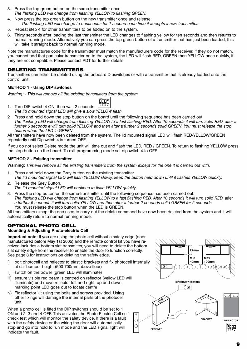
OPTIONAL PhOTO CELLMounting & Adjusting Photo-electric CellImportant note: If you are using the photo cell without a safety edge (door manufactured before May 1st 2005) and the remote control kit you have re-ceived includes a bottom slat transmitter, you will need to delete the bottom slat safety edge from the receiver to enable the door to function correctly. See page 8 for instructions on deleting the safety edge.
i) bolt photocell and reflector to plastic brackets and fix photocell internally at car bumper height (500-700mm above floor)
ii) switch on the power (green LED will illuminate)iii) ensure visible red beam is centred on reflector (yellow LED will
illuminate) and move reflector left and right, up and down, marking point LED goes out to locate centre
iv) Fix reflector kit using the bolts and screws provided. Using other fixings will damage the internal parts of the photocell unit.
When a photo cell is fitted the DIP switches should be set to 1 ON and 2, 3 and 4 OFF. This activates the Photo Electric Cell self check test which will monitor the safety device. If there is a fault with the safety device or the wiring the door will automatically stop and go into hold to run mode and the LED signal light will indicate the fault.
�
Min 40mm
27mm
Max 100mm
REFLECTORBRACKET
SENSITIVITY SETTING
RECEIVER
�0
ADDITIONAL FEATuRES OF ThE SECEuROSMARTPin Lock & Stall Detection
When an open command is given from the fully closed, close limit position and pin/ground locks are left in place, SeceuroS-mart detects the motor starting to stall when tension is applied to the curtain; SeceuroSmart automatically stops the door and then reverses direction sending the shutter back to the fully closed position.
If the motor starts to stall part way through an open movement (this could occur if a person/object is drawn in to the coil or a person/object is lifted by the shutter), SeceuroSmart automatically stops the door and then reverses direction for ap-proximately 2 seconds, releasing or lowering anything that was lifted or trapped by the shutter.
Every time a pin/ground lock or stall detect occurs a ten second time out disables the open command, preventing the operator from repeatedly trying to open the door with the pin/ground locks engaged.
A visual indication is given on the signal LED as detailed in the System Status Indication section.
Please note that during a power failure if the unit is fed from a PDT battery backup, the controls revert to ‘Dead Man’ operation and pin/ground lock or stall detect is disabled.
Thermal Trip Monitoring
SeceuroSmart constantly monitors the thermal trip embedded inside the motor. If the motor is operated frequently it will over-heat and activate the thermal trip. Displaying the thermal trip activation prevents the user from calling out an engineer, only to find the shutter started working again, as the thermal trip automatically reset as the motor cooled down.
A visual indication is given on the signal LED as detailed in the System Status Indication section.
Relay Weld Monitoring
SeceuroSmart monitors the power relays that switch electricity to the motor. The use of redundancy technology (a legal requirement) ensures that the shutter can always be brought to the stop position irrespective of mechanical or electrical failure of the motor power relays.
A visual indication is given on the signal LED as detailed in the System Status Indication section.
Service Counter
SeceuroSmart Counts the number of times the door is opened, this information can then be used to help provide the correct level of service required to maintain the door in optimum condition. The current count can be displayed on the signal LED by pressing and holding the stop button on ‘power up’ or ‘reset’.
The count is then shown in the following format
Quick RED flash (1/4 sec on 1/4 sec off) indicates thousands (one flash per thousand operations)
Quick YELLOW flash indicates hundreds (one flash per hundred operations)
Quick GREEN flash indicates tens (one flash per ten operations)
Quick RED flash indicates units (one flash for each operation)
A long flash (0ne second) of any of the above colours indicates a zero for that count.
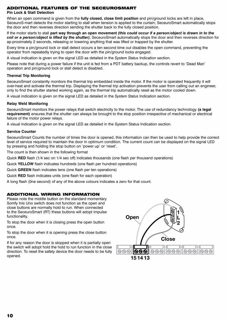
ADDITIONAL wIRING INFORMATIONPlease note the middle button on the standard momentary Somfy Inis Uno switch does not function as the open and close buttons are normally hold to run. When connected to the SeceuroSmart (RT) these buttons will adopt impulse functionality.
To stop the door when it is closing press the open button once.
To stop the door when it is opening press the close button once.
If for any reason the door is stopped when it is partially open the switch will adopt hold the hold to run function in the close direction. To reset the safety device the door needs to be fully opened.
1L2
15 14 13
Open
Close
�� ��
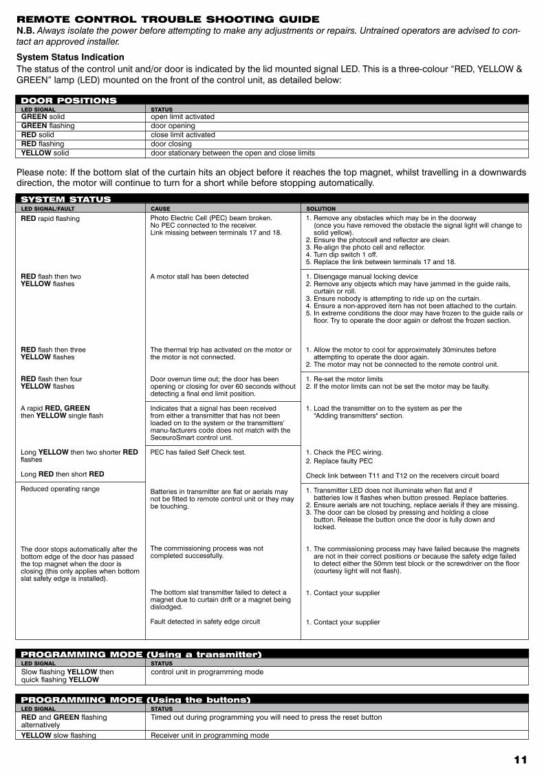
REMOTE CONTROL TROubLE ShOOTING GuIDEN.B. Always isolate the power before attempting to make any adjustments or repairs. Untrained operators are advised to con-tact an approved installer.
System Status IndicationThe status of the control unit and/or door is indicated by the lid mounted signal LED. This is a three-colour “RED, YELLOW & GREEN” lamp (LED) mounted on the front of the control unit, as detailed below:
GREEN solid open limit activatedGREEN flashing door openingRED solid close limit activatedRED flashing door closingYELLOW solid door stationary between the open and close limits
DOOR POSITIONSLEDSIGNAL STATUS
1. Remove any obstacles which may be in the doorway (once you have removed the obstacle the signal light will change to
solid yellow).2. Ensure the photocell and reflector are clean.3. Re-align the photo cell and reflector.4. Turn dip switch 1 off. 5. Replace the link between terminals 17 and 18.
1. Disengage manual locking device2. Remove any objects which may have jammed in the guide rails,
curtain or roll.3. Ensure nobody is attempting to ride up on the curtain.4. Ensure a non-approved item has not been attached to the curtain.5. In extreme conditions the door may have frozen to the guide rails or
floor. Try to operate the door again or defrost the frozen section.
1. Allow the motor to cool for approximately 30minutes before attempting to operate the door again.
2. The motor may not be connected to the remote control unit.
1. Re-set the motor limits2. If the motor limits can not be set the motor may be faulty.
1. Load the transmitter on to the system as per the "Adding transmitters" section.
1. Check the PEC wiring.2. Replace faulty PEC
Check link between T11 and T12 on the receivers circuit board
1. Transmitter LED does not illuminate when flat and if batteries low it flashes when button pressed. Replace batteries.2. Ensure aerials are not touching, replace aerials if they are missing.3. The door can be closed by pressing and holding a close button. Release the button once the door is fully down and locked.
1. The commissioning process may have failed because the magnets are not in their correct positions or because the safety edge failed to detect either the 50mm test block or the screwdriver on the floor (courtesy light will not flash).
1. Contact your supplier
1. Contact your supplier
RED rapid flashing
RED flash then two YELLOW flashes
RED flash then threeYELLOW flashes
RED flash then four YELLOW flashes
A rapid RED, GREENthen YELLOW single flash
Long YELLOW then two shorter RED flashes
Long RED then short RED
Reduced operating range
The door stops automatically after the bottom edge of the door has passed the top magnet when the door is closing (this only applies when bottom slat safety edge is installed).
Photo Electric Cell (PEC) beam broken.No PEC connected to the receiver. Link missing between terminals 17 and 18.
A motor stall has been detected
The thermal trip has activated on the motor or the motor is not connected.
Door overrun time out; the door has been opening or closing for over 60 seconds without detecting a final end limit position.
Indicates that a signal has been received from either a transmitter that has not been loaded on to the system or the transmitters' manu-facturers code does not match with the SeceuroSmart control unit.
PEC has failed Self Check test.
Batteries in transmitter are flat or aerials may not be fitted to remote control unit or they may be touching.
The commissioning process was not completed successfully.
The bottom slat transmitter failed to detect a magnet due to curtain drift or a magnet being dislodged.
Fault detected in safety edge circuit
SySTEM STATuSLEDSIGNAL/FAULT CAUSE SOLUTION
Slow flashing YELLOW then control unit in programming mode quick flashing YELLOW
PROGRAMMING MODE (using a transmitter)LEDSIGNAL STATUS
RED and GREEN flashing Timed out during programming you will need to press the reset button alternatively YELLOW slow flashing Receiver unit in programming mode
PROGRAMMING MODE (using the buttons)LEDSIGNAL STATUS
Please note: If the bottom slat of the curtain hits an object before it reaches the top magnet, whilst travelling in a downwards direction, the motor will continue to turn for a short while before stopping automatically.
��
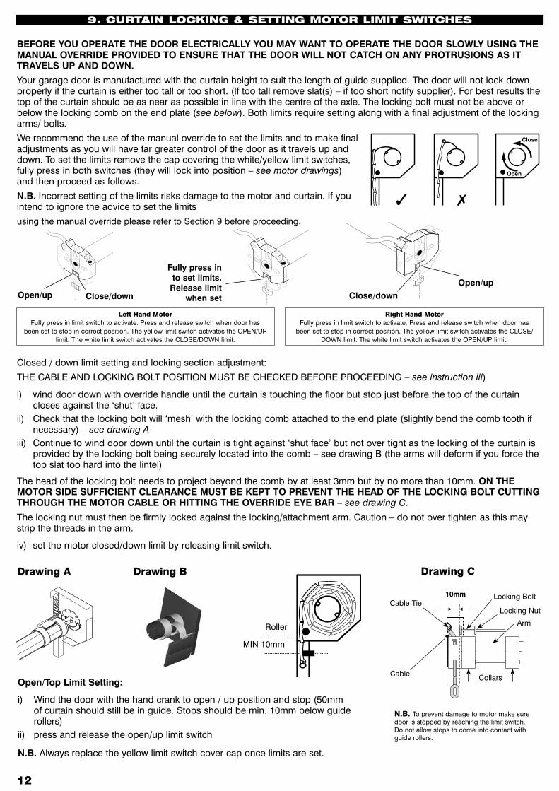
BEFORE YOU OPERATE THE DOOR ELECTRICALLY YOU MAY WANT TO OPERATE THE DOOR SLOWLY USING THE MANUAL OVERRIDE PROVIDED TO ENSURE THAT THE DOOR WILL NOT CATCH ON ANY PROTRUSIONS AS IT TRAVELS UP AND DOWN.
Your garage door is manufactured with the curtain height to suit the length of guide supplied. The door will not lock down properly if the curtain is either too tall or too short. (If too tall remove slat(s) – if too short notify supplier). For best results the top of the curtain should be as near as possible in line with the centre of the axle. The locking bolt must not be above or below the locking comb on the end plate (see below). Both limits require setting along with a final adjustment of the locking arms/ bolts.
We recommend the use of the manual override to set the limits and to make final adjustments as you will have far greater control of the door as it travels up and down. To set the limits remove the cap covering the white/yellow limit switches, fully press in both switches (they will lock into position – see motor drawings) and then proceed as follows.
N.B. Incorrect setting of the limits risks damage to the motor and curtain. If you intend to ignore the advice to set the limits
using the manual override please refer to Section 9 before proceeding.
9. CuRTAIN LOCkING & SETTING MOTOR LIMIT SwITChES
Closed / down limit setting and locking section adjustment:
THE CABLE AND LOCKING BOLT POSITION MUST BE CHECKED BEFORE PROCEEDING – see instruction iii)
i) wind door down with override handle until the curtain is touching the floor but stop just before the top of the curtain closes against the ‘shut’ face.
ii) Check that the locking bolt will ‘mesh’ with the locking comb attached to the end plate (slightly bend the comb tooth if necessary) – see drawing A
iii) Continue to wind door down until the curtain is tight against ‘shut face’ but not over tight as the locking of the curtain is provided by the locking bolt being securely located into the comb – see drawing B (the arms will deform if you force the top slat too hard into the lintel)
The head of the locking bolt needs to project beyond the comb by at least 3mm but by no more than 10mm. ON THE MOTOR SIDE SUFFICIENT CLEARANCE MUST BE KEPT TO PREVENT THE HEAD OF THE LOCKING BOLT CUTTING THROUGH THE MOTOR CABLE OR HITTING THE OVERRIDE EYE BAR – see drawing C.
The locking nut must then be firmly locked against the locking/attachment arm. Caution – do not over tighten as this may strip the threads in the arm.
iv) set the motor closed/down limit by releasing limit switch.
Open/Top Limit Setting:
i) Wind the door with the hand crank to open / up position and stop (50mm of curtain should still be in guide. Stops should be min. 10mm below guide rollers)
ii) press and release the open/up limit switch
N.B. Always replace the yellow limit switch cover cap once limits are set.
N.B. To prevent damage to motor make sure door is stopped by reaching the limit switch. Do not allow stops to come into contact with guide rollers.
Close
Open
DrawingA DrawingB
Close
Open
MIN 10mm
Roller
DrawingC
10mm
Cable
Locking Bolt
Locking Nut
Arm
Collars
Cable Tie
LeftHandMotorFully press in limit switch to activate. Press and release switch when door has
been set to stop in correct position. The yellow limit switch activates the OPEN/UP limit. The white limit switch activates the CLOSE/DOWN limit.
RightHandMotorFully press in limit switch to activate. Press and release switch when door has
been set to stop in correct position. The yellow limit switch activates the CLOSE/DOWN limit. The white limit switch activates the OPEN/UP limit.
Open/up Close/down Close/downOpen/up
Fully press in to set limits.
Release limit when set
�� ��
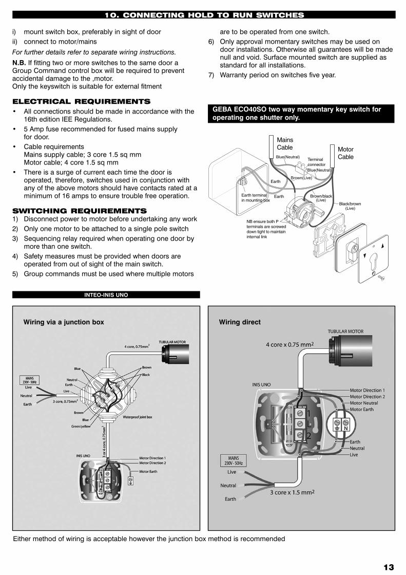
10. CONNECTING hOLD TO RuN SwITChES
GEBA ECO40SO two way momentary key switch for operating one shutter only.
Blue(Neutral)
Blue(Neutral)
Brown(Live)
(Live)
(Live)
INTEO-INIS UNO
Wiring directWiring via a junction box
Either method of wiring is acceptable however the junction box method is recommended
i) mount switch box, preferably in sight of doorii) connect to motor/mains
For further details refer to separate wiring instructions.
N.B. If fitting two or more switches to the same door a Group Command control box will be required to prevent accidental damage to the ,motor. Only the keyswitch is suitable for external fitment
ELECTRICAL REquIREMENTS• All connections should be made in accordance with the
16th edition IEE Regulations.• 5 Amp fuse recommended for fused mains supply
for door.• Cable requirements
Mains supply cable; 3 core 1.5 sq mm Motor cable; 4 core 1.5 sq mm
• There is a surge of current each time the door is operated, therefore, switches used in conjunction with any of the above motors should have contacts rated at a minimum of 16 amps to ensure trouble free operation.
SwITChING REquIREMENTS1) Disconnect power to motor before undertaking any work2) Only one motor to be attached to a single pole switch3) Sequencing relay required when operating one door by
more than one switch.4) Safety measures must be provided when doors are
operated from out of sight of the main switch.5) Group commands must be used where multiple motors
are to be operated from one switch.6) Only approval momentary switches may be used on
door installations. Otherwise all guarantees will be made null and void. Surface mounted switch are supplied as standard for all installations.
7) Warranty period on switches five year.
��
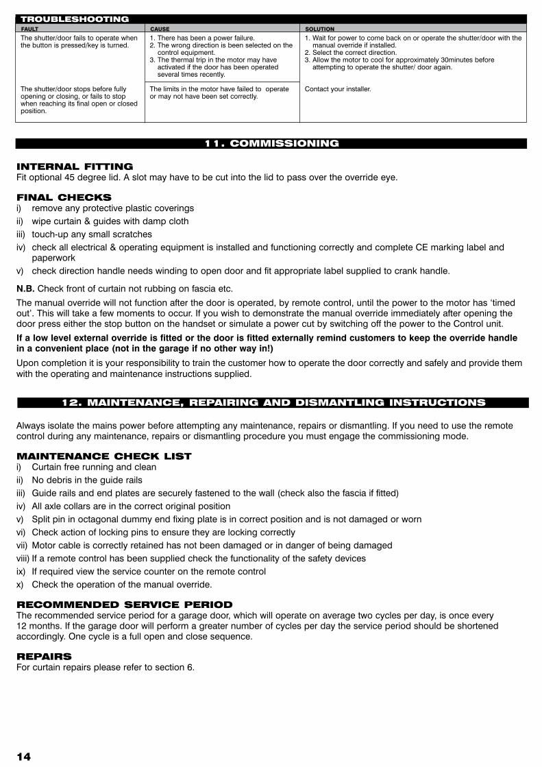
INTERNAL FITTINGFit optional 45 degree lid. A slot may have to be cut into the lid to pass over the override eye.
FINAL ChECkSi) remove any protective plastic coveringsii) wipe curtain & guides with damp clothiii) touch-up any small scratchesiv) check all electrical & operating equipment is installed and functioning correctly and complete CE marking label and
paperworkv) check direction handle needs winding to open door and fit appropriate label supplied to crank handle.
N.B. Check front of curtain not rubbing on fascia etc.
The manual override will not function after the door is operated, by remote control, until the power to the motor has ‘timed out’. This will take a few moments to occur. If you wish to demonstrate the manual override immediately after opening the door press either the stop button on the handset or simulate a power cut by switching off the power to the Control unit.
If a low level external override is fitted or the door is fitted externally remind customers to keep the override handle in a convenient place (not in the garage if no other way in!)
Upon completion it is your responsibility to train the customer how to operate the door correctly and safely and provide them with the operating and maintenance instructions supplied.
11. COMMISSIONING
12. MAINTENANCE, REPAIRING AND DISMANTLING INSTRuCTIONS
1. Wait for power to come back on or operate the shutter/door with the manual override if installed.
2. Select the correct direction. 3. Allow the motor to cool for approximately 30minutes before
attempting to operate the shutter/ door again.
Contact your installer.
The shutter/door fails to operate when the button is pressed/key is turned.
The shutter/door stops before fullyopening or closing, or fails to stop when reaching its final open or closed position.
1. There has been a power failure.2. The wrong direction is been selected on the
control equipment.3. The thermal trip in the motor may have
activated if the door has been operated several times recently.
The limits in the motor have failed to operate or may not have been set correctly.
TROubLEShOOTINGFAULT CAUSE SOLUTION
Always isolate the mains power before attempting any maintenance, repairs or dismantling. If you need to use the remote control during any maintenance, repairs or dismantling procedure you must engage the commissioning mode.
MAINTENANCE ChECk LISTi) Curtain free running and cleanii) No debris in the guide railsiii) Guide rails and end plates are securely fastened to the wall (check also the fascia if fitted)iv) All axle collars are in the correct original positionv) Split pin in octagonal dummy end fixing plate is in correct position and is not damaged or wornvi) Check action of locking pins to ensure they are locking correctlyvii) Motor cable is correctly retained has not been damaged or in danger of being damagedviii) If a remote control has been supplied check the functionality of the safety devicesix) If required view the service counter on the remote controlx) Check the operation of the manual override.
RECOMMENDED SERvICE PERIODThe recommended service period for a garage door, which will operate on average two cycles per day, is once every 12 months. If the garage door will perform a greater number of cycles per day the service period should be shortened accordingly. One cycle is a full open and close sequence.
REPAIRSFor curtain repairs please refer to section 6.
�� ��
REPLACING MOTORS / DuMMy ENDS / ANTI-FALL bACk SPRINGS:1) Lower the curtain to the fully closed position.2) Disconnect the curtain from the axle.3) If the axle contains an anti-fall back spring the tension must be removed from the spring before attempting to remove
the axle. To remove the tension you must rotate the axle in the direction which would open the door the number of turns stated on the label provided.
4) Isolate the mains power then disconnect the motor leads from the control unit.5) Remove screws securing motor octagonal fixing plate and lever out retaining tabs with a screwdriver6) Remove split pin from dummy end shaft and slide shaft free of fixing plate.7) Lift axle out8) If you need to replace or remove the motor, unbolt the octagonal fixing plate and drill out rivets in the axle securing the
motor, make sure that any loose drilled out rivet ‘slugs’ are removed from inside the axle to prevent them making an unnecessary rattling noise.
9) The dummy end and anti-fall back spring are also held in place by rivets and should be removed in a similar manner.10) Replace the motor / dummy end / anti-fall back spring, re-rivet and refit the octagonal fixing plate to the motor end.11) Install the axle assembly as per section 4 remembering to tension the anti-fall back spring if one is installed.12) Re-connect motor lead to the control unit.13) Reset motor limits.14) If a remote control has been supplied you will need to follow the set up procedure outlined in section 8.
REvERSING MOTOR hAND:1) Lower the curtain to the fully closed position. 2) Disconnect the curtain from the axle.3) If the axle contains an anti-fall back spring the tension must be removed from the spring before attempting to remove
the axle. To remove the tension you must rotate the axle in the direction which would open the door the number of turns stated on the label provided.
4) Isolate the mains power then disconnect the motor leads from the control unit. 5) Remove screws securing motor octagonal fixing plate and lever out retaining tabs with a screwdriver 6) Remove split pin from dummy end shaft and slide shaft free of fixing plate. 7) Lift the axle out 8) Drill out the rivet securing the dummy end / spring to the axle (hidden beneath end collar) make sure that any loose
drilled out rivet ‘slugs’ are removed from inside the axle to prevent them making an unnecessary rattling noise 9) Drill out the rivets holding the collars in place or tap the rivets along the channel using a screwdriver and a mallet 10) Slide out dummy end / spring and remove all collars 11) If an anti-fall back spring has been fitted you will need to remove the spring inserts at both ends of the spring and swap
them round to reverse the handing of the spring. The spring inserts are held in place with circlips. 12) Refit collars, ensuring that the ‘snail’ points towards the flat of the endplate (see page 3 drawing F). Replace dummy end
/ spring.13) Re-rivet dummy end / spring / collars 14) Refit the axle assembly following the instructions provided in section 4.
DISMANTLING PROCEDuRE1) Lower the curtain to the fully closed position.2) Disconnect the curtain from the axle.3) If you would like to use the curtain again you should cover the axle with bubble wrap or similar packaging material to
avoid damaging the curtain when you remove it.4) Remove the curtain by lifting it up and over the axle.3) If the axle contains an anti-fall back spring the tension must be removed from the spring before attempting to remove
the axle. To remove the tension you must rotate the axle in the direction which would open the door the number of turns stated on the label provided.
4) Isolate the mains power then disconnect the motor leads from the control unit.5) remove screws securing motor octagonal fixing plate and lever out retaining tabs with a screwdriver6) Remove split pin from dummy end shaft and slide shaft free of fixing plate.7) lift axle assembly out8) Unfasten and remove the guide rails, end plates and fascia (if supplied).

��
13. SECEuROSMART TEChNICAL SPECIFICATION
T1 Live T11 0Vdc
T2 Neutral T12 Stopswitchinput
T3 Earth T13 Openswitchinput
T4 Motorearth T14 Switchcommon
T5 Lamplive T15 Closeswitchinput
T6 Lampneutral T16 PECautotestoutput
T7 Motorneutral T17 Switchcommon
T8 Motorclose T18 PECinput
T9 Motoropen T19 Antenna
T10 +12Vdc T20 Screen
TERMINAL DESCRIPTION
SW1 Reset SW4 Close
SW2 DIP switches SW5 Stop
SW6 Open
SwITCh DESCRIPTION
Supply Voltage 230 VAC / 50hZ
Supply Current 6 Amps (Max)
Transformer power VA 6VA
Operating temperature (Centigrade) -10 / +30
Relay 10A @ 230VAC
Triac 1A @ 230VAC
Courtesy light enclosure 40 watts maximum
Short circuit protection 6.3A 20mm HRC fuse
Auxiliary 12VDC 20mA
Photo Electric Cell Input NPN
Self Check Output 5 VDC
Safe Edge Input Wireless
Receiver frequency 433.92Mhz
Security (Rolling Code) Keeloq
IP Rating 44
Dimensions (mm) H 200 / W 134 / D 68
Connections T1 to T18 Removable
TERMINAL DESCRIPTION