electric power systems research - متلبی paper/p92_matlabi...a.h.m.a. rahim, e.p. nowicki /...
TRANSCRIPT

Ps
Aa
b
a
ARRAA
KWISR
1
davaiwwsomscs[
bora
0d
Down
Electric Power Systems Research 81 (2011) 149–157
Contents lists available at ScienceDirect
Electric Power Systems Research
journa l homepage: www.e lsev ier .com/ locate /epsr
erformance of a grid-connected wind generation system with a robustusceptance controller
.H.M.A. Rahima,∗, E.P. Nowickib
Department of Electrical Engineering, K.F. University of Petroleum & Minerals, KFUPM Box 349, Dhahran 31261, Saudi ArabiaDepartment of Electrical & Computer Engineering, University of Calgary, Calgary, AB, Canada T2N 1N4
r t i c l e i n f o
rticle history:eceived 22 April 2008eceived in revised form 10 March 2010ccepted 6 August 2010vailable online 15 September 2010
a b s t r a c t
Wind turbine driven induction generators are vulnerable to transient disturbances like wind gusts andlow voltages on the system. The fixed capacitor at the generator terminal or the limited support fromthe grid may not be able to provide the requisite reactive power under these abnormal conditions. Thispaper presents a susceptance control strategy for a variable speed wound-rotor induction generatorwhich can cater for the reactive power requirement. The susceptance is adjusted through a robust feed-
eywords:ind turbine system
nduction generatorusceptance controlobust control
back controller included in the terminal voltage driven automatic excitation control circuit. The fixedparameter robust controller design is carried out in frequency domain using multiplicative uncertaintymodeling and H∞ norms. The robustness of the controller has been evaluated through optimally tuned PIDcontrollers. Simulation results show that the robust controller can effectively restore normal operationfollowing emergencies like sudden load changes, wind gusts and low voltage conditions. The proposedrobust controller has been shown to have adequate fault ride through capabilities in order to be able to
ents
meet connection requirem. Introduction
Large penetration of wind power to the grid is, though, veryesirable it has its associated disadvantages. Simple connection ofn induction generator to the grid may give rise to unacceptableoltage rise at the bus, not delivering the maximum available powert the desired efficiency. Wind turbines mostly do not take partn voltage and frequency control and if a disturbance occurs, the
ind turbines are sometimes disconnected and then reconnectedhen normal operation has been resumed [1]. Variation of wind
peed from time to time due to gusts and disturbances like faultsn the asynchronous as well as the synchronous part of the systemay pose serious control problems [2]. Transients arising in either
ystem may propagate into the other causing malfunctions in theontrols. Voltage collapse has been reported following transienthort circuits in the connecting networks with large wind farms3].
The transient performance can normally be enhanced for by
lade pitch control on the turbine side. Pitch control for powerutput and speed fluctuations has been reported in [4,5]. Brakingesistor control for fault ride through has been proposed in [6]. Volt-ge, current and power control on the generator side is reported∗ Corresponding author. Tel.: +966 3 8604986; fax: +966 3 8603535.E-mail address: [email protected] (A.H.M.A. Rahim).
378-7796/$ – see front matter © 2010 Elsevier B.V. All rights reserved.oi:10.1016/j.epsr.2010.08.002
loaded from http://www.elearnica.ir
defined by transmission system operators.© 2010 Elsevier B.V. All rights reserved.
in [7,8]. Adaptive control strategies [9] and robust controllers [10]have been reported in the literature for maximum power pointtracking. Fuzzy-logic based power and efficiency maximization aswell as robust speed control have also been reported [11,12]. Whilesome of these are open-loop strategies, the PI controllers used insome of these studies depend on feedback of terminal voltage, cur-rent and speed of the machine. In the PI designs, departure from thenominal operating point degrades controller performance signifi-cantly due to nonlinearity of the system. In general, control designsconsidering the entire system dynamic model is lacking.
This study proposes a susceptance control strategy for transientcontrol of a variable speed wind generation system with a wound-rotor type of induction machine. A fixed parameter robust dampingcontroller has been proposed which acts along with an automaticsusceptance control circuit driven by changes in terminal voltage.The robust design uses the uncertainty modeling and the controllerfunction is arrived at through frequency response methods. Simula-tion studies demonstrate the effectiveness of the robust controllerin restoring normal operation following severely depressed voltageconditions.
2. The system model
Fig. 1 shows the variable speed wind turbine-generator systemconsidered in this study. The system consists of a horizontal axisturbine-generator connected to the power grid through back-to-

150 A.H.M.A. Rahim, E.P. Nowicki / Electric Power Systems Research 81 (2011) 149–157
Nomenclature
d–q subscripts for direct and quadrature axesRs, Rr stator, rotor resistancexs, xr stator, rotor reactancexm mutual reactance ds, qs d, q axes stator flux linkage dr, qr d, q axes rotor flux linkageids, iqs d, q axes stator currentidr, iqr d, q axes rotor currentvds, vqs d, q axes stator voltageωe generator rotor angular speedωo base angular speedVs generator terminal voltageVsr generator terminal reference voltagePm, Pe input, output power of generatorH inertia constant of generator
blaccttStircet
2
w
P
Hb(re
�
KsE, TsE gain, time constant of exciter circuitTw washout block time constant
ack converters and the transmission lines. The integrated locaload and the proposed control circuits are shown to be connectedt the generator terminal. A wound-rotor induction generator isonsidered in the study. It is assumed that a variable susceptanceontrol circuit is installed at the AC side of the system along withhe local load. The variable susceptance can be obtained by con-rolling firing angle of the thyristors in the static VAR system. TheVC system contains a fixed capacitor (FC) needed for normal exci-ation of the induction generator. If additional capacitor excitations required the thyristor switched capacitor (TSC) is switched in. Aeduction in capacitance is achieved by switching in the thyristorontrolled reactor (TCR) into the circuit. The models for the differ-nt components of the wind turbine-generator system are given inhe following.
.1. The wind turbine model
The mechanical power output of a wind turbine is related to theind speed Vω by [2]:
m = 12�ACpV
3ω (1)
ere, � is the air density and A is the swept area by the turbinelades. The power coefficient Cp is a function of both tip speed ratio�) and the blade pitch angle (ˇ). The tip speed ratio which is the
atio of linear speed at the tip of blades to the speed of wind isxpressed as:= ωmR
Vw(2)
Fig. 1. Wind generator-infinite bus system.
Fig. 2. Speed vs. power output characteristics of a wind turbine.
where R and ωm are the radius and the mechanical angular veloc-ity, respectively, of the wind turbine rotor. Expressions of Cp as afunction of � and ˇ employed in [13] are:
Cp(�,ˇ) = 0.5176(
116�i
− 0.4ˇ − 5)e−21/�i + 0.0068�
1�i
= 1�+ 0.08ˇ
− 0.035ˇ3 + 1
(3)
Fig. 2 shows the power–speed characteristics curves of a typicalwind turbine for various wind velocities. For a given wind speed Vw
and pitch angle ˇ, the power coefficient Cp is constructed for a setof values of � (usually in the range 0–14) using relationship (3). Fora certain value of Cp and �mechanical power is calculated through(1) and (2) gives the corresponding rotor speed. The plots in Fig. 2are for zero blade pitch angle.
Wind speed changes continuously and its magnitude are ran-dom over any interval. For simulation of randomly changing windspeed, probability distribution of the random number should beknown. The average wind speed is usually considered constant forsome intervals (say about 10 min). The fluctuations during suchintervals can be considered to be combination of constant and sinu-soidal variation around the mean speed, Vm. A typical formula is[14]:
Vω = Vm[
1 − 0.2 cos(
2�t20
)− 0.5 cos
(2�t600
)](4)
The wind gust can be simulated by varying the magnitude andfrequency of the sinusoidal fluctuation.
2.2. The induction machine model
The induction machine model can be derived from the gener-alized induction motor model of Krause [15]. The voltage currentrelations along the d–q axes of the stator and rotor circuits, respec-tively, are:
1ωo ds − ωe
ωo qs + Rsids = vds,
1ωo qs + ωe
ωo ds + Rsiqs = vqs (5)
1ωo dr − s qr + Rr idr = vdr,
1ωo qr + s dr + Rr iqr = vqr (6)
The flux linkages and currents are related through:
ds = xsids + xmidr, qs = xsiqs + xmiqr (7)
dr = xr idr + xmids, qr = xr iqr + xmiqs (8)

A.H.M.A. Rahim, E.P. Nowicki / Electric Power
s
l
(
Ie
T
c
2
ta
I
wYtraf
2
fi
wtcfi
w
2
iv
2
Fig. 3. Functional block diagram of the susceptance control circuit.
The slip s used in the above equations is defined as:
= ωo −ωrωo
(9)
The rotor motion of the machine is expressed through the fol-owing slip equation:
2H)s = Te − Tm − D �s (10)
n the above �s is the change in slip from the steady value, andlectrical torque Te is written as:
e = qridr − driqr (11)
In the generation mode the slip will be negative and the statorurrents will reverse their directions.
.3. Transmission line and load models
Retaining the notation for induction motor operation, the equa-ion for current in the transmission line in Fig. 1 can be writtens:
= (Vb − Vs)Y12 − VsY11 (12)
here Y12 = g12 + jb12 is the transmission line admittance,11 = g11 + jb11 is the local load admittance, Vs is the genera-or terminal voltage, and Vb is the grid voltage which is assumed toemain constant. Writing the generator stator current and voltages, I = ids + jiqs and Vs = vds + jvqs, Eq. (12) can be expressed in theorm:
vds(g11 + g12) − vqs(b12 + b11) = −ids + Vbg12,
vds(b12 + b11) + vqs(g11 + g12) = −iqs + Vbb12 (13)
.4. The susceptance controller
A block diagram of the variable susceptance control circuit con-guration is shown in Fig. 3.
The controller compares the generator terminal voltage (Vs)ith a reference signal (Vsr) and injects susceptance (�B) at the
erminal to keep proper excitation of the system. The control cir-uit has provision of including additional control (u) to the thyristorring circuit.
The dynamic equations for the control block in Fig. 3 can beritten as:
d�B
dt= − 1
TSE[KSE(Vs − Vsr) +�B] + KSEu
TSE(14)
.5. The composite dynamic model
The converters of the variable speed wind generation system aren cascade with the generator stator. The time constants of the con-erter electronics are fairly small compared to the time constants
Systems Research 81 (2011) 149–157 151
of the induction machine, and hence are not included in the anal-ysis. For closed form dynamic representation, the turbine poweroutput given in Fig. 2 has to be expressed as an analytic functionof the generator rotor speed or slip. For example, for wind velocityof 9 m/s, the expression for the power output as a function of rotorspeed n (rpm) is obtained by using MATLAB function polyfit as:
Pm = −2.102×10⁻¹³n6+1.305×10⁻⁹n5−2.965×10⁻⁶n4+28.750
× 10−4n3 − 1.030n2 + 143.348n− 4033.626 (15)
From the set of Eqs. (5)–(8), the derivatives of the generator cur-rents ids, iqs, idr, and iqr are obtained in terms of vds, vqs, vdr, and vqr .Expressions for vds and vqs obtained from (13) are then substitutedinto them to yield four differential equations in terms of generatorcurrents. These along with slip derivative Eq. (10) and susceptancecontroller Eq. (14) are combined to give the closed form state equa-tions as:
x = f [x, u] (16)
Here, x is the vector of states [idsiqsidriqrs�B].
3. Robust susceptance control
The additional controller in the voltage sensitive automaticsusceptance control circuit has been designed to provide robustdamping performance. The design principle of the controller fol-lowed by construction of the controller function is presented inthis section.
3.1. The robust design principle
The control problem for the nonlinear power system model isstated as: given the system represented by set of Eq. (16), design acontroller which will bring the system to normal operation follow-ing a perturbation in the system. Since there is no general methodof designing a stabilizing control for the nonlinear system, the pro-cedure starts with a design which will be valid around a nominaloperating condition. The linearized system of state equations arewritten as:
X = AX + Bu, Y = CX (17)
The C matrix will depend on the chosen output variable Y. Thechanges in operation of the nonlinear system (16) can be con-sidered as changes in the elements of the system matrices (A,B, C). These perturbations are modeled as multiplicative uncer-tainties and robust design procedure is applied to the perturbedlinear systems. The design is carried out using the minimizationof performance measures expressed in terms of H∞ norms. A fre-quency domain based graphical construction procedure has beenemployed for the robust control design. The uncertainty model, therobust stability criterion, and an algorithm for the design processare given in the following [16].
Suppose that the linearized plant having a nominal transferfunction P belongs to a bounded set of transfer functions. Considerthat the perturbed transfer function resulting from the variationsin operating conditions can be expressed in the form:
P = (1 +˝W2)P; P = C[sI − A]−1B (18)
Here, W is a fixed stable transfer function, also called the weight,
and˝ is a variable transfer function satisfying ||˝||∝ < 1. The infin-ity norm (∝-norm) of a function is the least upper bound of itsabsolute value, also written as∥∥˝∥∥∝ = sup
ω
∣∣˝(jω)∣∣, and is the
largest value of gain on a Bode magnitude plot. In the multiplicative
1 Power Systems Research 81 (2011) 149–157
ua∣∣∣∣SpfrT∣∣∣
ortWr
∥∥
Cs∥∥
fiCts
|fo
∣∣
w
∣∣
Ttedns
1
23
45
67
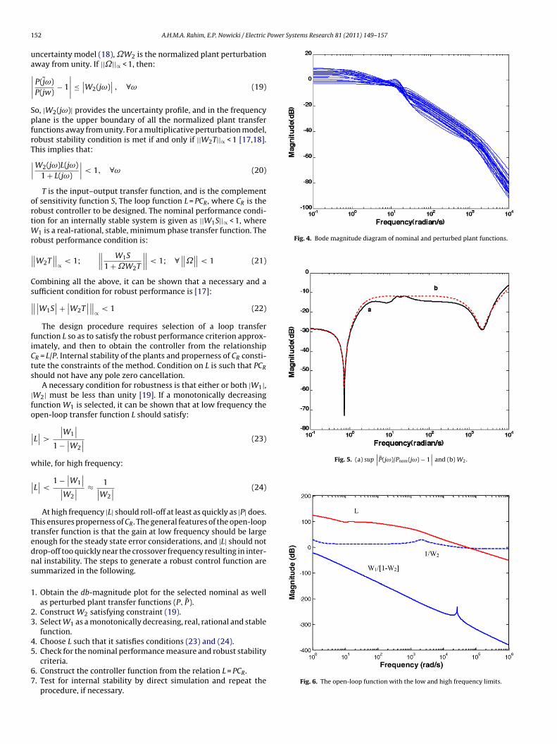
Fig. 4. Bode magnitude diagram of nominal and perturbed plant functions.
Fig. 5. (a) sup∣∣P(jω)/Pnom(jω) − 1
∣∣ and (b) W2.
52 A.H.M.A. Rahim, E.P. Nowicki / Electric
ncertainty model (18),˝W2 is the normalized plant perturbationway from unity. If ||˝||∝ < 1, then:
P(jω)P(jw)
− 1
∣∣∣∣ ≤∣∣W2(jω)
∣∣ , ∀ω (19)
o, |W2(jω)| provides the uncertainty profile, and in the frequencylane is the upper boundary of all the normalized plant transferunctions away from unity. For a multiplicative perturbation model,obust stability condition is met if and only if ||W2T||∝ < 1 [17,18].his implies that:
W2(jω)L(jω)1 + L(jω)
∣∣∣< 1, ∀ω (20)
T is the input–output transfer function, and is the complementf sensitivity function S, The loop function L = PCR, where CR is theobust controller to be designed. The nominal performance condi-ion for an internally stable system is given as ||W1S||∝ < 1, where
1 is a real-rational, stable, minimum phase transfer function. Theobust performance condition is:
W2T∥∥
∝ < 1;∥∥∥ W1S
1 +˝W2T
∥∥∥< 1; ∀∥∥˝∥∥< 1 (21)
ombining all the above, it can be shown that a necessary and aufficient condition for robust performance is [17]:∣∣W1S
∣∣ +∣∣W2T
∣∣∥∥∝ < 1 (22)
The design procedure requires selection of a loop transferunction L so as to satisfy the robust performance criterion approx-mately, and then to obtain the controller from the relationshipR = L/P. Internal stability of the plants and properness of CR consti-ute the constraints of the method. Condition on L is such that PCR
hould not have any pole zero cancellation.A necessary condition for robustness is that either or both |W1|,
W2| must be less than unity [19]. If a monotonically decreasingunction W1 is selected, it can be shown that at low frequency thepen-loop transfer function L should satisfy:
L∣∣>
∣∣W1
∣∣1 −
∣∣W2
∣∣ (23)
hile, for high frequency:
L∣∣< 1 −
∣∣W1
∣∣∣∣W2
∣∣ ≈ 1∣∣W2
∣∣ (24)
At high frequency |L| should roll-off at least as quickly as |P| does.his ensures properness of CR. The general features of the open-loopransfer function is that the gain at low frequency should be largenough for the steady state error considerations, and |L| should notrop-off too quickly near the crossover frequency resulting in inter-al instability. The steps to generate a robust control function areummarized in the following.
. Obtain the db-magnitude plot for the selected nominal as wellas perturbed plant transfer functions (P, P).
. Construct W2 satisfying constraint (19).
. Select W1 as a monotonically decreasing, real, rational and stablefunction.
. Choose L such that it satisfies conditions (23) and (24).
. Check for the nominal performance measure and robust stabilitycriteria.
. Construct the controller function from the relation L = PCR.
. Test for internal stability by direct simulation and repeat theprocedure, if necessary.
Fig. 6. The open-loop function with the low and high frequency limits.

A.H.M.A. Rahim, E.P. Nowicki / Electric Power Systems Research 81 (2011) 149–157 153
3
tt
P
ccma
ti
W1.959 × 105s+ 4.8735 × 10⁶
8s+ 1.2996 × 10⁸(26)
a
W
ff
C
arwm
4
w
controllers resulting in system isolation. The proposed robust strat-egy is very effective in holding the large swings under control andreturning to steady condition in a very short period.
Figs. 10 and 11 show the variation of the generator power outputand rotor speed variations, respectively, following a short 1 s wind
Fig. 7. Plot of nominal and robust performance indices.
.2. The controller design
For nominal induction generator power output of 0.86 pu theransfer function (P) for the wind turbine-induction generator sys-em is obtained as:
= 5141.5(s+ 5129.56)(s+ 6.91)(s2 + 13.2779s+ 340.35)
(s+ 3.336)(s+ 15.576)(s2 + 8.746s+ 259.771)(s2 + 3169.457s+ 2.863 × 10⁶)(25)
In Fig. 3, the input to the controller is considered to be the rotorurrent deviation. Power output in the ranges of 0.3–1.1 pu werehosen to generate the off-nominal set of plant function P. The log-agnitude vs. frequency plots for the nominal and perturbed plants
re shown in Fig. 4.The quantity
∣∣P(jω)/Pnom(jω) − 1∣∣ is constructed for each per-
urbed plant P(jω) and the upper envelope in the frequency planes fitted to the function:
2(s) = 2.0468s4 + 1871.466s3 + 9.357 × 10⁶s2 + 9.9048 × 10⁸ +s4 + 48003.04s3 + 3.6147 × 10⁷s2 + 1.096 × 10
Fig. 5 shows the supremum of the functions∣∣P(jω)/Pnom(jω) − 1
∣∣nd the fitted upper envelope W2.
A Butterworth filter with Kc = 0.1 and fc = 10 is selected as:
1(s) = Kcf 2c
s3 + 2s2fc + 2sf 2c + f 3
c
(27)
For W1 and W2 selected above and for the open-loop transferunction satisfying the loop requirements, the controller transferunction obtained through the relation C = L/P is:
R = 100(s+ 4)(s2 + 8s+ 100)(s+ 0.1)(s2 + 50s+ 200)
(28)
The log-magnitude plot of the open-loop function, the robustnd nominal performance measures are shown in Figs. 6 and 7,espectively. It can be observed that the nominal performance asell as robust stability measures is both satisfied. However, theargin for the nominal performance measure is larger.
. Testing the robust controller
The robust control function (28) arrived in the previous sectionas tested on the wind generator system given in Fig. 1 for a num-
Fig. 8. Induction generator power output variations following a 40% input torquepulse for 0.2 s with: (a) no control and (b) proposed robust susceptance control.
ber of disturbance conditions and for a range of operation. The datafor the system is given in Appendix A.
4.1. Simulation results
Figs. 8 and 9 show the power output and stator terminal volt-age variations of the generator, respectively, when a 40% torquepulse for 0.2 s is applied to the generator. The no control responsesshow that the system is seriously perturbed at the onslaught of thedisturbance. While the subsequent transients settle down quicklybecause of grid support, the initial thrust may disable the existing
Fig. 9. Induction generator stator voltage variations following a 40% input torquepulse for 0.2 s with: (a) no control and (b) proposed robust susceptance control.

154 A.H.M.A. Rahim, E.P. Nowicki / Electric Power Systems Research 81 (2011) 149–157
Fg
gsnru
4
dFaTltpd
4
r
F(
ig. 10. Induction generator power output variations following a 1 s duration windust with: (a) no control and (b) proposed robust susceptance control.
ust. The uncontrolled responses show the oscillations are quiteignificant even for this small gust. As expected, the controls willot going to be effective while the gust continues. However, theobust controller is able to hold the subsequent swings very muchnder control restoring normal operation quickly.
.2. Testing the robustness of operation
The effectiveness of the proposed robust controller on theynamic performance on a range of operation was tested.igs. 12 and 13 show the generator power output and speed devi-tions, respectively, following a 40% torque step for 0.2 s duration.hree widely spaced operating conditions reported here are foroadings of (a) 106%, (b) 86%, and (c) 50%. Following the disturbance,he robust controller restores normal operation quickly for all theoints of operation. The performance of the controller, however,epends on the selected range of operation in the design process.
.3. Evaluation of controller performance
A qualitative comparison of the response with the proposedobust controller was made with conventional PID controller. The
ig. 11. Generator rotor speed variations following a 1 s duration wind gust with:a) no control and (b) proposed robust susceptance control.
Fig. 12. Grid-connected induction generator output variations following 40% torquepulse for 0.2 s for the three loading conditions: (a) 106%, (b) 86%, and (c) 50%.
PID controller is normally placed in the feedback path. A washout isincluded in cascade with the controller to disable the control actionin steady state. Starting with the linearized model (17), the gains ofthe controller were obtained through placement of the dominantpoles at the proper location in the left-half s-plane. The followingequation is then solved for KP, KI and KD for desired pole locations:
�Tw1 + �Tw
[KP + KI
�+ KD�
]= 1
C(�I − A)−1B(29)
In the absence of susceptance control the dominant eigenvalues,contributed by the d–q axes rotor currents, yields a damping ratio of0.1316 for a nominal generator power output of 86%. The dampingratio is fairly small and is considered to be responsible for the oscil-lations in the system following the disturbances. A PID controllerwas designed to relocate the eigenvalues corresponding to the d–qaxes rotor currents corresponding to damping ratio of 0.1776. Thegains of the PID controller were found to be −17.98, 16.53, and 2.31,
respectively. The washout time constant was optimized at 0.44.The response with the designed controller at the nominal loadingprovides reasonable performance in terms of restoration of nor-mal condition. However, for loadings of 105 and 50%, which areFig. 13. Speed variations of the induction generator corresponding to this figure forthe loading conditions: (a) 106%, (b) 86%, and (c) 50%.
A.H.M.A. Rahim, E.P. Nowicki / Electric Power Systems Research 81 (2011) 149–157 155
Flc
aFtaTtpts
4
gtpaTlccwnstttGir
j
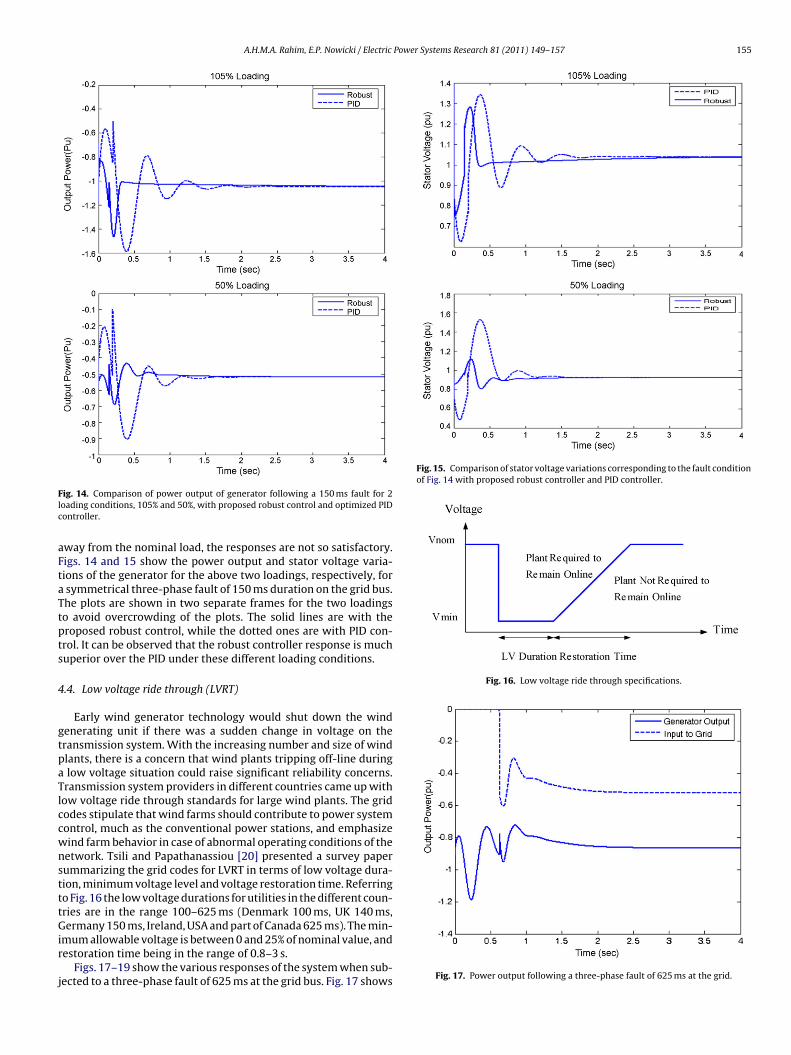
Fig. 15. Comparison of stator voltage variations corresponding to the fault conditionof Fig. 14 with proposed robust controller and PID controller.
Fig. 16. Low voltage ride through specifications.
ig. 14. Comparison of power output of generator following a 150 ms fault for 2oading conditions, 105% and 50%, with proposed robust control and optimized PIDontroller.
way from the nominal load, the responses are not so satisfactory.igs. 14 and 15 show the power output and stator voltage varia-ions of the generator for the above two loadings, respectively, forsymmetrical three-phase fault of 150 ms duration on the grid bus.he plots are shown in two separate frames for the two loadingso avoid overcrowding of the plots. The solid lines are with theroposed robust control, while the dotted ones are with PID con-rol. It can be observed that the robust controller response is muchuperior over the PID under these different loading conditions.
.4. Low voltage ride through (LVRT)
Early wind generator technology would shut down the windenerating unit if there was a sudden change in voltage on theransmission system. With the increasing number and size of windlants, there is a concern that wind plants tripping off-line duringlow voltage situation could raise significant reliability concerns.ransmission system providers in different countries came up withow voltage ride through standards for large wind plants. The gridodes stipulate that wind farms should contribute to power systemontrol, much as the conventional power stations, and emphasizeind farm behavior in case of abnormal operating conditions of theetwork. Tsili and Papathanassiou [20] presented a survey paperummarizing the grid codes for LVRT in terms of low voltage dura-ion, minimum voltage level and voltage restoration time. Referringo Fig. 16 the low voltage durations for utilities in the different coun-ries are in the range 100–625 ms (Denmark 100 ms, UK 140 ms,
ermany 150 ms, Ireland, USA and part of Canada 625 ms). The min-mum allowable voltage is between 0 and 25% of nominal value, andestoration time being in the range of 0.8–3 s.
Figs. 17–19 show the various responses of the system when sub-ected to a three-phase fault of 625 ms at the grid bus. Fig. 17 shows Fig. 17. Power output following a three-phase fault of 625 ms at the grid.

156 A.H.M.A. Rahim, E.P. Nowicki / Electric Power Systems Research 81 (2011) 149–157
Fig. 18. Voltage variations following a 625 ms fault at the grid.
F
ttrvimcTb
5
aptibtolro
Table 1Generator, transmission line and turbine data (values are in pu except statedotherwise).
Generator Transmissionline and exciter
Turbine
Rs = 0.04373 R = 0.8 Blade swept area, A = 577 m2
Rr = 0.024 X = 1 Air density, � = 1.225 kg/m3
xs = 3.418 KSE = 2 Blade radius, R = 13.5 mxr = 3.418 TSE = 0.1 Gear-ratio = 1:23
[
[
[
[
ig. 19. Variation of stator current following a 625 ms three-phase fault at the grid.
he power output of the generator and also the power supplied tohe grid. It can be observed from the generator terminal voltageesponse of Fig. 18 that following the fault the generator terminaloltage depresses immediately. However, the proposed controllers able to inject enough reactive power to restore the generator ter-
inal voltage. In the process, the generator voltage and the statorurrent is pushed higher requiring reversing the excitation process.his causes several swings in generator voltage and current as cane observed from the responses shown in Figs. 18 and 19.
. Conclusions
Improvement of dynamic performance of a grid-connected vari-ble speed wind turbine with wound-rotor induction generatorower system employing a variable susceptance excitation con-roller is investigated. An additional robust controller which worksn conjunction with an automatic susceptance control circuit driveny terminal voltage deviation is designed. The performance ofhe fixed parameter robust controller has been tested for vari-
us loading conditions and various emergency scenarios like sharpoad change, wind gust and system under voltages. Simulationesults show that the robust controller can help restore normalperating conditions very quickly for the different disturbances[
[[
xm = 3.289 Pitch angle, ˇ = 0.D = 0.00 Mean wind speed Vw = 9 m/sH = 3f = 60 Hz
considered. The robust controller has demonstrated capability toride though low voltage conditions according to the requirementsspecified by transmission system operators. The controller has alsobeen observed to perform very well over a good range of opera-tion. Comparison of the response with optimally tuned PID controldemonstrates the superiority of the robust design.
Acknowledgements
This work was supported by KFUPM/SABIC Fast Track researchgrant SAB-2006-04. The authors wish to acknowledge the supportprovided by the King Fahd University of Petroleum & Minerals.
Appendix A.
See Table 1.
References
[1] J.G. Slootweg, S.W.H. Hann, H. Polinder, W.L. Kling, General model for repre-senting variable speed wind turbines in power system dynamic simulations,IEEE Trans. Power Syst. 18 (2003) 144–151.
[2] E.S. Abdin, W. Xu, Control design and dynamic performance analysis of a windturbine-induction generator unit, IEEE Trans. Energy Convers. 15 (2000) 91–96.
[3] V. Akhmatov, H. Knudsen, A dynamic stability limit of grid connection inductiongenerators, in: Proc. Power & Energy System Intl. Conference, 2000.
[4] T. Senjyu, R. Sakamoto, N. Urasaki, H. Higa, K. Uezato, T. Funabashi, Outputpower control of wind turbine generator by pitch angle control using minimumvariance control, J. Electr. Eng. Jpn. 154 (2006) 10–18.
[5] J.G. Slootweg, S.W.H. Haan, H. Polinder, W.L. Kling, General model for repre-senting variable speed wind turbines in power system dynamics simulations,IEEE Trans. Power Syst. 18 (2003) 144–151.
[6] A. Causebrook, D.J. Atkinson, A.G. Jack, Fault ride-through of large wind farmsusing dynamic breaking resistors, IEEE Trans. Power Syst. 22 (2007) 966–975.
[7] D. Seyoum, M.F. Rahman, C. Grantham, Terminal voltage control of a wind tur-bine driven isolated induction generator using stator oriented field control, in:Proc. IEEE-2003 Applied Power Electronics Conf and Exposition, Florida, USA,2003, pp. 846–852.
[8] C. Chai, Y. Chitra, K. Methaprayoon, W.J. Lee, Reactive compensation tech-niques to improve the ride-through of induction generators during disturbance,in: Proc. IEEE 39th IAS Annual meeting, Industry Application Conf., 2004, pp.2044–2050.
[9] R. Spee, S. Bhowmik, J.R. Enslin, Adaptive variable strategies for variable speeddoubly fed wind power generation systems, in: Conf. Records of IEEE IndustryApplications Society Annual Meeting, 1, 1994, pp. 545–552.
10] C. Pournaras, A. Soldatos, S. Papathanassiou, A. Kladas, Robust controller forvariable speed stall regulated wind turbines, in: Proc. 16th Intl. Conference onElectrical Machines, 2004.
11] M.G. Simoes, B.K. Bose, R.J. Spiegel, Fuzzy logic based intelligent control of avariable speed cage machine wind generation system, IEEE Trans. Power Electr.12 (1997) 87–95.
12] R.M. Hilloowala, A.M. Sharaf, A rule-based fuzzy logic controller for a PWMinverter in a stand alone wind energy conversion scheme, IEEE Trans. Ind. Appl.32 (1996) 57–65.
13] T.K.A. Brekken, A novel control scheme for a doubly-fed induction wind gen-erator under unbalanced grid voltage conditions, Ph.D. Thesis, University ofMinnesota, 2005.
14] R. Datta, V.T. Ranganathan, Variable-speed wind power generation using dou-bly fed wound rotor induction machine—comparison with alternative schemes,IEEE Trans. Energy Convers. 17 (2002) 414–421.
15] P.C. Krause, Analysis Electric Machinery, McGraw-Hill, New York, 1986.16] A.H.M.A. Rahim, M.F. Kandlawala, Robust STATCOM voltage controller design
using loop-shaping technique, Electr. Power Syst. Res. 68 (2004) 61–74.

[
[
A.H.M.A. Rahim, E.P. Nowicki / Electric Power
17] J.C. Doyle, B.A. Francis, A.R. Tannenbaum, Feedback Control Theory, MacMillanPublishing Co., New York, 1992.
18] A. Chao, M. Athans, Stability Robustness to Unstructured Uncertainty for LinearTime Invariant Systems, The Control Handbook, CRC Press/IEEE Press, 1996.
[
[
Systems Research 81 (2011) 149–157 157
19] M.A. Dahleh, l1 Robust Control: Theory, Computation and Design, The ControlHandbook, CRC Press/IEEE Press, 1996.
20] M. Tsili, S. Papathanassiou, A review of grid code technical requirements forwind farms, IET Renew. Power Gen. 3 (2009) 308–332.