electric actuator new - rs components...
TRANSCRIPT

RoHSSlider Type
NewNew
Max. work load: 60 kg
Positioning repeatability: ±0.02 mm
Size 40 added!
Max. stroke: 2000 mm
Transfer speed: 2000 mm/s
Ball Screw Drive Series LEFS
Belt Drive Series LEFB
Size: 16, 25, 32, 40
Size: 16, 25, 32
Ball Screw Drive Series LEFS Size: 25, 32, 40
Controller Controller
�Step Data Input Type
� 64 positioning points� Teaching box, controller setting kit input
� 14 positioning points� Control panel setting
Series LECP6/LECA6�Programless Type
Series LECP1� Pulse input type� Absolute encoder (LECSB)� Built-in positioning function (LECSA)
�AC Servo Motor ControllerSeries LECSA/LECSB
NewNew
NewNew
NewNew
n
Step Motor (Servo/24 VDC) AC Servo Motor CServo Motor (24 VDC)
Type
Type
Step Motor (Servo/24 VDC) TServo Motor (24 VDC)
AC Servo Motor (100/200/400 W)
m
0 mmmm
00 mm/s
es LEFB
T/ W)
Series LEFS Si
ewwNeNewNewNeNeNeww� High output motor (100/200/400 W)� Improved high speed transfer ability� High acceleration compatible (5000 mm/s2)� Pulse input type� With internal absolute encoder (LECSB specifications)
Electric Actuator
CAT.EUS100-87C-UK
Series LEF
NewNew

Hei
ght
LEFS16 LJ1H10
80
90
4040
4040
Ball Screw Drive/Series LEFS Size: 16, 25, 32, 40
Max. work load: 60 kgPositioning repeatability: ±0.02 mm
Belt Drive/Series LEFB
Size: 16, 25, 32
Max. stroke: 2000 mm
Transfer speed: 2000 mm/s
Ball Screw Drive/Series LEFS Size: 25, 32, 40
� High output motor (100/200/400 W)� Improved high speed transfer ability� High acceleration compatible (5000 mm/s2)� Pulse input type� With internal absolute encoder (LECSB specifications)
Positioning pin hole
Hei
ght
Ball screw
Heig
htSlider type with lower height
Non-magnetizing operation type lock mechanism (Option)
Drop prevention in case of power failure (Maintained)
Series LEF
Speed
Wor
k lo
ad
Step Motor
Servo Motor
Compatible motors�Step Motor (Servo/24 VDC)
Ideal for transfer of high loads at a low speed�Servo Motor (24 VDC)
Stable at a high speed and silent operation�AC Servo Motor (100/200/400 W)
Ideal for high speed transfer and compatible with high acceleration (5000 mm/s2).
�CompactHeight/width dimensions reduced by approx. 50%
�Easy mounting of the body/Reduction of the installation labour
Compared with SMC LJ1 series (Work load: 10 kg)
Equipped with seal bands as standardCovers the guide, ball screw and belt. Prevents grease from splashing and external foreign matter from entering.
Step Motor (Servo/24 VDC) Servo Motor (24 VDC)
Step Motor(Servo/24 VDC) Servo Motor (24 VDC)
AC Servo Motor (100/200/400 W)
Speed
Wor
k lo
ad Step Motor
AC Servo Motor
Servo Motor
Series LEFS only
Slider type with lower height
Size Height [mm]
16253240
40
48
60
68
NewNew
Possible to mount the main body without removing the external cover.
Belt
Features 1

Series Variations
Application Examples
Ball Screw Drive/Series LEFS
Belt Drive/Series LEFB
1 The size corresponds to the bore of the air cylinder with an equivalent thrust (for the operation using ball screws).2 Strokes shown in ( ) are produced upon receipt of order. Strokes other than those mentioned above are available as a special order.
Precise positioning of work pieces Pick and placeLoad and unload transfer of work pieces Vertical transfer
1 The size corresponds to the bore of the air cylinder with an equivalent thrust (for the operation using ball screws).2 Strokes shown in ( ) are produced upon receipt of order. Strokes other than those mentioned above are available as a special order.3 Belt drive actuator cannot be used for vertically mounted applications.
Electric Actuator/Slider Type
Type1
Size
Step motor(Servo/24 VDC)
Servo motor(24 VDC)
16
25
32
40
16
25
25
32
40
Page
1
45
5
10
6
12
8
16
10
20
5
10
6
12
Work load: Horizontal [kg] Work load: Vertical [kg] Speed [mm/s]Lead[mm] Stroke [mm] 2
100, 200, 300, (400)
100, 200, 300, (400)
10 20 30 10 20 200 400 600 800 100040 50 60
100, 200, 300, (400)500, (600)
100, 200, 300, (400)500, (600), (700), (800)
100, 200, 300, (400)500, (600)
Type Size 1
Step motor(Servo/24 VDC)
Servo motor(24 VDC)
Page
15
16
25
32
16
25
48
48
48
48
48
Work load: Horizontal [kg] 3Equivalent lead[mm] Stroke [mm] 2
(300), 500, (600), (700)800, (900), 1000
(300), 500, (600), (700)800, (900), 1000
(300), 500, (600), (700), 800, (900)1000, (1200), (1500), (1800), (2000)
(300), 500, (600), (700), 800, (900)1000, (1200), (1500), (1800), (2000)
(300), 500, (600), (700), 800, (900)1000, (1200), (1500), (1800), (2000)
5 10 15 20Speed [mm/s]
500 1000 1500 2000
200, 300, (400), 500, (600)(700), 800, (900), (1000)
AC Servo motor(100/200/400 W)
6
12
8
16
10
20
100, 200, 300, (400)500, (600)
200, 300, (400), 500, (600)(700), 800, (900), (1000)
100, 200, 300, (400)500, (600), (700), (800)
NewNew
NewNew
30
Features 2
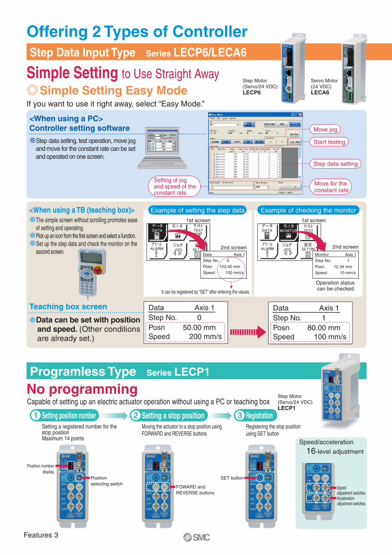
Example of setting the step data Example of checking the monitor
Simple Setting Easy Mode
Data Axis 1Step No. 0
Posn 123.45 mm
Speed 100 mm/s
Monitor Axis 1
Step No. 1
Posn 12.34 mm
Speed 10 mm/s
It can be registered by “SET” after entering the values.
Operation status can be checked.
Simple Setting to Use Straight Away
No programming
Start testing
Move for the constant rate
Setting of jogand speed of theconstant rate
Step data setting
Move jog
<When using a PC>Controller setting software
�Step data setting, test operation, move jog and move for the constant rate can be set and operated on one screen.
Programless Type Series LECP1
LECP6 LECA6
If you want to use it right away, select “Easy Mode.”
<When using a TB (teaching box)>
Teaching box screen
�The simple screen without scrolling promotes ease of setting and operating.
�Pick up an icon from the first screen and select a function.�Set up the step data and check the monitor on the
second screen.
�Data can be set with position and speed. (Other conditions are already set.)
Setting position numberSetting a registered number for the stop positionMaximum 14 points
Moving the actuator to a stop position using FORWARD and REVERSE buttons
Registering the stop position using SET button
1 Setting a stop position2 Registration3
Position selecting switch
FOWARD and REVERSE buttons
Position numberdisplay
SET button
Offering 2 Types of Controller
Step Motor (Servo/24 VDC)
Servo Motor (24 VDC)
LECP1
Step Motor (Servo/24 VDC)
Step Data Input Type Series LECP6/LECA6
Data Axis 1Step No. 0Posn 50.00 mmSpeed 200 mm/s
Data Axis 1Step No. 1Posn 80.00 mmSpeed 100 mm/s
Capable of setting up an electric actuator operation without using a PC or teaching box
Speed/acceleration
16-level adjustment
1st screen 1st screen
2nd screen2nd screen
Speed adjustment switchesAcceleration adjustment switches
Features 3
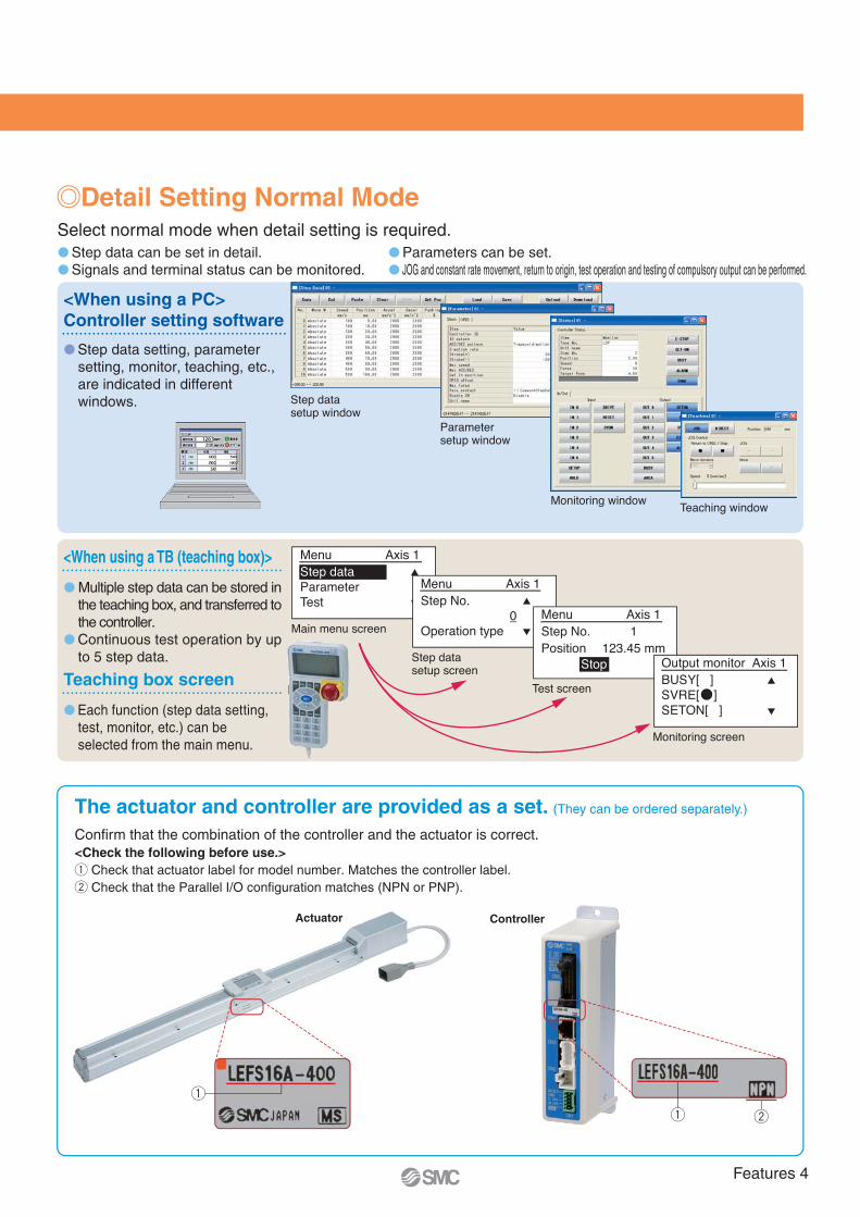
� Step data setting, parameter setting, monitor, teaching, etc., are indicated in different windows.
Controller setting software<When using a PC>
Select normal mode when detail setting is required.
<When using a TB (teaching box)>
Teaching box screen
� Step data can be set in detail.� Signals and terminal status can be monitored.
� Parameters can be set.� JOG and constant rate movement, return to origin, test operation and testing of compulsory output can be performed.
� Multiple step data can be stored in the teaching box, and transferred to the controller.
� Continuous test operation by up to 5 step data.
� Each function (step data setting, test, monitor, etc.) can be selected from the main menu.
The actuator and controller are provided as a set. (They can be ordered separately.)
Confirm that the combination of the controller and the actuator is correct.<Check the following before use.>q Check that actuator label for model number. Matches the controller label.w Check that the Parallel I/O configuration matches (NPN or PNP).
q w
Actuator Controller
q
Detail Setting Normal Mode
Menu Axis 1Step No. 0 Operation type
Menu Axis 1Step No. 1Position 123.45 mm Stop Output monitor Axis 1
BUSY[ ]SVRE[ ] SETON[ ]
Main menu screen
Step datasetup screen
Test screen
Monitoring screen
Menu Axis 1Step dataParameter Test
Step data setup window
Parameter setup window
Monitoring windowTeaching window
Features 4

Function
Setting Items
Number of step data
Operation command (I/O signal)
Completion signal
� Input the numerical value from controller setting software (PC)
� Input the numerical value from teaching box
� Input the numerical value from controller setting software (PC)
� Input the numerical value from teaching box
� Direct teaching
� JOG teaching
64 points
Step No. [IN∗] input ⇒ [DRIVE] input
[INP] output
� Select using controller operation buttons
� Direct teaching
� JOG teaching
14 points
Step No. [IN∗] input only
[OUT∗] output
Item Step data input typeLECP6/LECA6
Programless typeLECP1
Step data “position” setting
Step data and parametersetting
Movement MOD
Speed
Position
Acceleration/Deceleration
Pushing force
Trigger LV
Pushing speed
Positioning force
Area output
In position
Stroke (+)
Stroke (–)
ORIG direction
ORIG speed
ORIG ACC
JOG
MOVE
Return to ORIG
Test drive
Compulsory output
DRV mon
In/Out mon
Active ALM
ALM Log record
Save/Load
Language
Step datasetting(Excerpt)
Parametersetting(Excerpt)
Test
Monitor
ALM
File
Other
Selection of “absolute position” and “relative position”
Transfer speed
[Position]: Target position
[Pushing]: Pushing start position
Acceleration/deceleration during movement
Rate of force during pushing operation
Target force during pushing operation
Speed during pushing operation
Force during positioning operation
Conditions for area output signal to turn ON
[Position]: Width to the target position
[Pushing]: How much it moves during pushing
+ side limit of position
– side limit of position
Direction of the return to the original position can be set.
Speed when returning to the original position
Acceleration when returning to the original position
Operation of the specified step data
ON/OFF of the output terminal can be tested.
Alarm currently being generated can be confirmed.
Alarm generated in the past can be confirmed.
Can be changed to Japanese or English.
Set at ABS/INC.
Set in units of 1 mm/s.
Set in units of 0.01 mm.
Set in units of 1 mm/s2.
Set in units of 1%.
Set in units of 1%.
Set in units of 1 mm/s.
Set to 100%.
Set in units of 0.01 mm.
Set to 0.5 mm or more.(Units: 0.01 mm)
Set in units of 0.01 mm.
Set in units of 0.01 mm.
Compatible
Set in units of 1 mm/s.
Set in units of 1 mm/s2.
Compatible
Compatible
Compatible
Compatible
Compatible
Compatible
Compatible
Compatible
Compatible
×
�
�
��×
×
×
×
×
×
×
×
×
×
�
×
�
�
×
�
×
�×
×
�
��
�
������
�
×
×
×
×
×
�
�
�
�
×
�
×
�×
×
�
��
�
������
�
�����
�
�
�
�
�
�
��
�
�
Fixed value (ABS)
Select from 16-level
Direct teaching
JOG teaching
Select from 16-level
Select from 3-level (weak, medium, strong)
No setting required (same value as pushing force)
Fixed value
Fixed value
Fixed value
Fixed value
Fixed value
Compatible
Fixed value
Fixed value
Compatible
Compatible
Compatible (display alarm group)
Item ContentsStep datainput type
LECP6/LECA6
Easymode
TB PC
Normalmode
TB, PC
Programless typeLECP1
Continuous operation at the set speed can be tested while the switch is being pressed.
Operation at the set distance and speed from the current position can be tested.
Current position, speed, force and thespecified step data can be monitored.
Current ON/OFF status of the inputand output terminal can be monitored.
Step data and parameter can besaved, forwarded and deleted.
�(Continuous operation)
Series LECP6/LECA6/LECP1
—
—
—
—
—
—
—
Press MANUAL button ( ) once forsizing operation(speed, sizing amount are specified values)
Hold down MANUAL button( ) for uniform sending(speed is specified value)
TB: Teaching box PC: Controller setting software
Features 5

System Construction
LECP6/LECA6LECP1 (Programless)
Part No.LEC-CN5-�LEC-CK4-�
Power supply for I/O signal 24 VDC
�USB cable
PC
Conversion unit�
(A-mini B type)
Part No.: LEC-T1-3EG�
with 3 m cable
�Controller setting kit (Option)
Controller setting kit(Communication cable, conversion unit and USB cable are included.)Part No.: LEC-W2
Or
Page 34
�Teaching box (Option) Page 35
Page 7
Page 15
Controller power supply 24 VDC
�Electric actuator
�Controller
�I/O cable
Motor cable (Fixed)�
Step data input typeLECP6/LECA6
Controller type
LECP6 (Step data input type)LECA6 (Step data input type)LECP1 (Programless type)
LE-CP-�LE-CA-�LE-CP-�
Robotic cableLE-CP-�-S
—LE-CP-�-S
Standard cable
�Actuator cableController type
Pages 31, 32, 42
LECP6/LECA6(Step data input type)LECP1 (Programless type)
Power supply plug (accessory)
Power supply cable (1.5m) (accessory)
Connection
�Power supply connectionController type
Pages 28, 40
Page 25 Page 37
Programless typeLECP1
Pages 33, 43
Series LEF
Slider Type
Series LEFSSeries LEFB
PLC
Communication cable�(3 m)
Supplied by customer
Supplied by customer
Features 6

Spe
ed
Time
Settlingtime
Spe
ed
Time
Settlingtime
� Controls the difference in movementbetween command value and actualmovement
� Automatically controls machine’s lowfrequency vibrations (up to 100 Hz)
Compatible control mode list (�: recommended setting, �: can be used, x: cannot be used, –: cannot be set)
LECSA(Incremental)
LECSB(Absolute)
Command method
Operation method
[Pulse-train]
Positioning operation Setting speed operation Setting torque operation
[ON/OFF signal]
Specify point table No.Positioning operation
Specify program No.Positioning operation
Control mode Note 1)
Position control
�
�
�
�
�
�
�3 points (Max.: 7 points) Note 4)
—
�4 programs (Max.: 8 programs) Note 4) Note 5)
—
Speed control Note 2) Torque control Note 3)
Point table method
Positioning
Program method
Controller type
Servo adjustment using auto gain tuning
With display setting function
Auto resonant filter function
Auto damping control function
Series LECSAC Servo Motor Controller
Note 1) Control switching mode cannot be used.Note 2) Make sure that has a limit on the external sensor etc. for avoiding collision with stroke end or workpiece.Note 3) Can only use for the actuator (Series LEY) compatible with pushing operation.Note 4) The settings must be changed in order to use various constant settings at maximum when using the point table method and program method.
Refer to the “Operation Manual” for required setting changes.Note 5) To control with the program method, order MR Configurator (setup software) LEC-MR-SETUP221 separately.
LECSA LECSB
� Pulse input type motor controller
� Compatible motor capacity: 100 W, 200 W, 400 W
� Compatible encoder : Incremental type Absolute type
� Power supply voltage : 100 to 120 VAC (50/60 Hz) 200 to 230 VAC (50/60 Hz)
One touch servo adjustment
One touch adjustment button
Display monitor,parameter, alarm
Display
Control of parametersettings, monitor displayetc. using push buttons
Settings
Display monitor,parameter, alarm
Display
Control of parametersettings, monitor displayetc. using push buttons
(With the front cover opened)
Settings
LECSA
LECSB
NewNew
Features 7
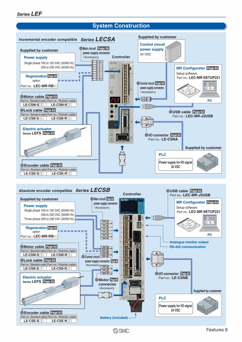
System Construction
Incremental encoder compatible Series LECSA
Controller
ControllerAbsolute encoder compatible Series LECSB
Power supply for I/O signal24 VDC
Power supplySingle phase 100 to 120 VAC (50/60 Hz)
200 to 230 VAC (50/60 Hz)
Supplied by customer
Analogue monitor outputRS-422 communication
Battery (included)
PC
MR ConfiguratorSetup softwarePart no.: LEC-MR-SETUP221
Page 64
Supplied by customer
Supplied by customer
Power supplySingle phase 100 to 120 VAC (50/60 Hz)
200 to 230 VAC (50/60 Hz)Three phase 200 to 230 VAC (50/60 Hz)
Supplied by customer
Control circuitpower supply24 VDC
Series LEF
Part no.: Standard cable Part no.: Robotic cableLE-CSM-S�� LE-CSM-R��
�Motor cable Page 63
Part no.: Standard cable Part no.: Robotic cableLE-CSM-S�� LE-CSM-R��
�Motor cable Page 63
�Main circuitpower supply connector∗Accessory
Page 59
�Main circuitpower supply connector∗Accessory
Page 60
Page 59Part no.: LEC-MR-RB-�
Regenerationoption
Page 63
Part no.: LEC-MR-RB-�
Regenerationoption
Page 63
Electric actuatorSeries LEFS Page 45
Electric actuatorSeries LEFS Page 45
�I/O connectorPart no.: LE-CSNA
�USB cablePart no.: LEC-MR-J3USB
Page 63
�I/O connectorPart no.: LE-CSNB
Page 63
Page 64
�USB cablePart no.: LEC-MR-J3USB
Page 64
�Control circuitpower supply connector∗Accessory
�Motorconnector ∗Accessory
Page 63
Part no.: Standard cable Part no.: Robotic cableLE-CSB-S�� LE-CSB-R��
�Lock cable
Page 63
Part no.: Standard cable Part no.: Robotic cableLE-CSB-S�� LE-CSB-R��
�Lock cable
Supplied by customer
PLC
Power supply for I/O signal24 VDC
PLC
Page 63�Encoder cablePart no.: Standard cable Part no.: Robotic cable
LE-CSE-S�� LE-CSE-R��
Page 63�Encoder cablePart no.: Standard cable Part no.: Robotic cable
LE-CSE-S�� LE-CSE-R��
PC
MR ConfiguratorSetup softwarePart no.: LEC-MR-SETUP221
Page 64
Page 60
Page 60
�Control circuitpower supply connector∗Accessory
Features 8
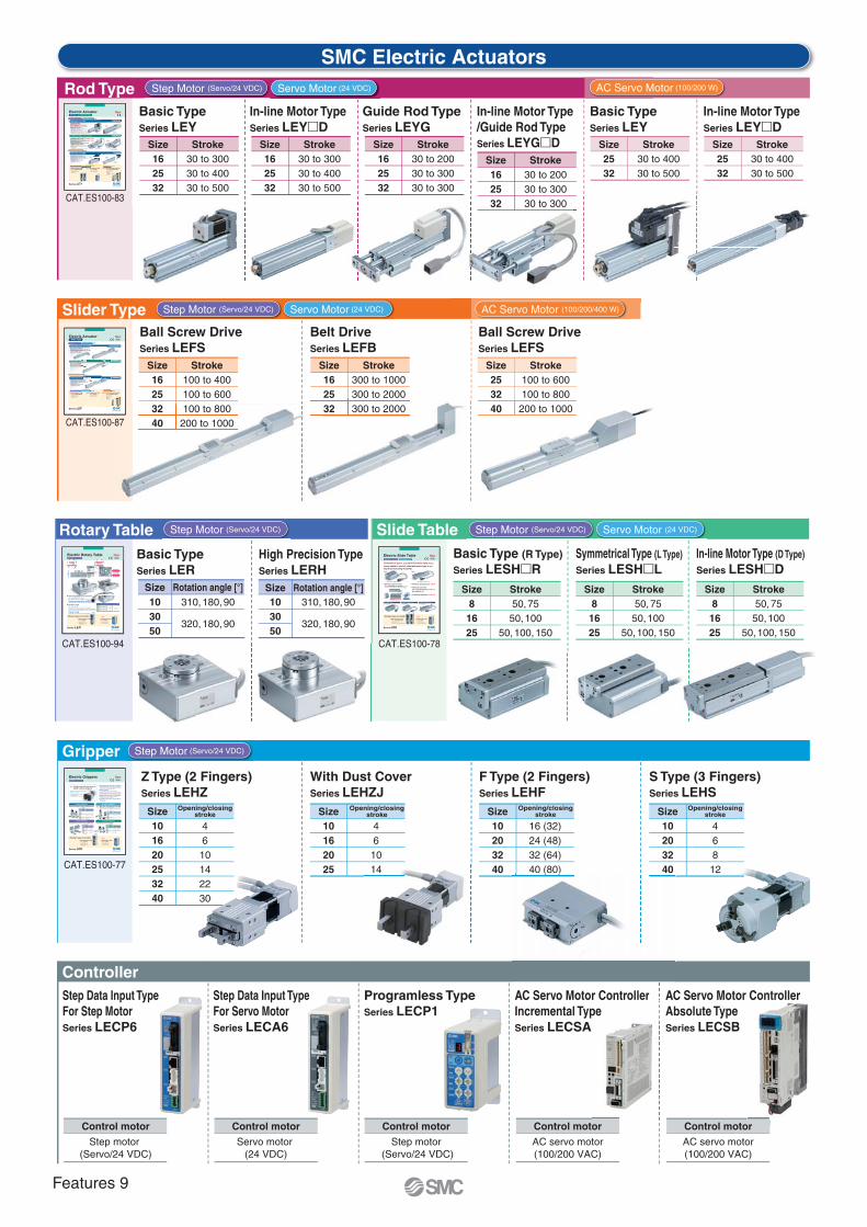
Control motor
Servo motor (24 VDC)
Control motor
Step motor (Servo/24 VDC)
Size8
1625
Stroke50, 75
50, 10050, 100, 150
Size8
1625
Stroke50, 75
50, 10050, 100, 150
Size8
1625
Stroke50, 7550, 100
50, 100, 150
Size101620253240
Opening/closingstroke
4610142230
Size103050
Rotation angle [°]310, 180, 90
320, 180, 90
Size10162025
Opening/closingstroke
461014
Size10203240
Opening/closingstroke
16 (32)24 (48)32 (64)40 (80)
Size10203240
Opening/closingstroke
468
12
Size103050
Rotation angle [°]310, 180, 90
320, 180, 90
Size Stroke Size Stroke
Ball Screw DriveSeries LEFS
Size Stroke
Ball Screw DriveSeries LEFS
Basic Type (R Type)Series LESH�R
Z Type (2 Fingers)Series LEHZ
Basic TypeSeries LER
Symmetrical Type (L Type)Series LESH�L
With Dust CoverSeries LEHZJ
In-line Motor Type (D Type)Series LESH�D
F Type (2 Fingers)Series LEHF
S Type (3 Fingers)Series LEHS
High Precision TypeSeries LERH
Step Data Input TypeFor Step MotorSeries LECP6
Step Data Input TypeFor Servo MotorSeries LECA6
Control motor
Step motor (Servo/24 VDC)
Programless TypeSeries LECP1
Control motor
AC servo motor(100/200 VAC)
AC Servo Motor ControllerIncremental TypeSeries LECSA
Control motor
AC servo motor(100/200 VAC)
AC Servo Motor ControllerAbsolute TypeSeries LECSB
Belt DriveSeries LEFB
Slide Table
Controller
SMC Electric Actuators
Slider Type
Rotary Table
Gripper
Rod Type
Size162532
Stroke30 to 30030 to 40030 to 500
Basic TypeSeries LEY
Size2532
Stroke30 to 40030 to 500
Basic TypeSeries LEY
Size2532
Stroke30 to 40030 to 500
In-line Motor TypeSeries LEY�D
Size162532
Stroke30 to 20030 to 30030 to 300
Guide Rod TypeSeries LEYG
Size162532
Stroke30 to 30030 to 40030 to 500
In-line Motor TypeSeries LEY�D
Size162532
Stroke30 to 20030 to 30030 to 300
In-line Motor Type/Guide Rod TypeSeries LEYG�D
14 ( )
AC Servo Motor Controller AC
or
100 to 400100 to 600100 to 800200 to 1000
300 to 1000300 to 2000300 to 2000
100 to 600100 to 800
200 to 1000
CAT.ES100-78
CAT.ES100-77
CAT.ES100-94 CAT.ES100-78
Step Motor (Servo/24 VDC)
Step Motor (Servo/24 VDC) Servo Motor (24 VDC)
Step Motor (Servo/24 VDC)
Step Motor (Servo/24 VDC) Servo Motor (24 VDC)
Step Motor (Servo/24 VDC) Servo Motor (24 VDC) AC Servo Motor (100/200 W)
AC Servo Motor (100/200/400 W)
CAT.ES100-83
CAT.ES100-87
16253240
162532
253240
RoHSSlider Type
NewNew
Max. work load: 60 kg
Positioning repeatability: ±0.02 mm
Size 40 added!
Max. stroke: 2000 mm
Transfer speed: 2000 mm/s
Ball Screw Drive Series LEFS
Belt Drive Series LEFB
Size: 16, 25, 32, 40
Size: 16, 25, 32
Ball Screw Drive Series LEFS Size: 25, 32, 40
Controller Controller
Step Data Input Type
64 positioning pointsTeaching box, controller
setting kit input
14 positioning pointsControl panel setting
Series LECP6/LECA6Programless TypeSeries LECP1
Pulse input typeAbsolute encoder
(LECSB)Built-in positioning function
(LECSA)
AC Servo Motor ControllerSeries LECSA/LECSB
NewNew
NewNew
NewNew
Step Motor (Servo/24 VDC) AC Servo Motor Servo Motor (24 VDC)
Type
Type
Step Motor (Servo/24 VDC) Servo Motor (24 VDC)
AC Servo Motor (100/200/400 W)
High output motor (100/200/400 W)Improved high speed transfer abilityHigh acceleration compatible (5,000 mm/s2)Pulse input typeWith internal absolute encoder
(LECSB specifications)
Electric Actuator
CAT.ES100-87C
Series LEF
NewNew
LowprofileLow
profileSpace-savingSpace-saving
H
SizeRotating torque [N·m]
Basic High torque
Max. speed [°/s]
Basic High torque
Positioning repeatability [°]
Basic High torque
10
30
50
0.2
0.8
6.6
0.3
1.2
10
420 280±0.05
(End: ±0.01)
Basic type [mm]
Model
LER10LER30LER50
H42
53
68
High precision type [mm]
Model
LERH10LERH30LERH50
H49
62
78
Possible to set speed, acceleration/deceleration, and position. Max. 64 points
Shock-less/high speed actuationMax. speed: 420°/sec (7.33 rad/sec)
Max. acceleration/deceleration: 3,000°/sec2 (52.36 rad/sec2)
Positioning repeatability: ±0.05°Repeatability at the end: ±0.01° (Pushing control/with external stopper)
Rotation angle320° (310°), 180°, 90°The value indicated in brackets shows the value for the LER10.
Energy-savingAutomatic 40% power reduction after the table has stopped.
Accommodateswiring and piping of work pieces.
Hollow shaft axis
Space-saving
Motor built-in
Value when an external stopper is mounted.
RoHS
Offering 2 types of controllerStep Data Input Type
64 positioning pointsTeaching box, controller setting kit input
14 positioning pointsControl panel setting
Series LECP6Programless TypeSeries LECP1
NewNew
NewNewStep Motor (Servo/24 VDC)
Electric Rotary Table
CAT.ES100-94B
Series LER
Prevents machining chips, dust, etc.,from getting inside
Prevents spattering of grease, etc.
Sealed-construction dust cover(Equivalent to IP50)
NewNewRoHS
Compact and light, various gripping forces
Gripping force [N]
6 to 14
16 to 40
52 to 130
84 to 210
Compact
2 to 6
3 to 8
11 to 28
—
—
Basic
Stroke/both sides
[mm]
4
6
10
14
22
30
Size
10
16
20
25
32
40
Series LEHZ
Gripping force[N]
3 to 7
11 to 28
48 to 120
72 to 180
Stroke/both sides
[mm]
16 (32)
24 (48)
32 (64)
40 (80)
Size
10
20
32
40
Series LEHF
( ): Long stroke
Gripping force [N]
Basic
2.2 to 5.5
9 to 22
36 to 90
52 to 130
Compact
1.4 to 3.5
7 to 17
—
—
Stroke/diameter
[mm]
4
6
8
12
Size
10
20
32
40
Series LEHS
Series LEHZJGripping force [N]
Basic
6 to 14
16 to 40
Compact
3 to 6
4 to 8
11 to 28
Stroke/both sides
[mm]
4
6
10
14
Size
10
16
20
25
Z Type (2 fingers) ZJ Type (2 fingers)
Long stroke, can hold various types of work pieces. Can hold round work pieces.
F Type (2 fingers) S Type (3 fingers)
With dust cover (Equivalent to IP50)Three types of cover material (Finger portion only)
NewNew
NewNew
NewNew
2-finger type with dust cover is added to electric grippers!
Step Motor (Servo/24 VDC)
Drop prevention function is provided.(Self-lock mechanism is provided for all series.)
Gripping force of the work pieces is maintained when stopped or restarted. The work pieces can be removed by hand.
Energy-saving Power consumption reduced by self-lock mechanism
Compact body sizes and long stroke variationsCan achieve the gripping force equivalent to the widely used air grippers.
Gripping check function is provided. Identify work pieces with different dimensions/detect mounting and removal of the work pieces.
Possible to set position, speed and force. (64 points)
Offering 2 types of controllerStep Data Input Type
64 positioning pointsTeaching box, controller setting kit input
14 positioning pointsControl panel setting
Series LECP6Programless TypeSeries LECP1
Electric Grippers
CAT.ES100-77D
Series LEH
Compact, Space-saving61% reduction in volume For R/L type
(compared to the SMC conventional products) Reduced cycle time
Maximum pushing force: 180 N
Positioning repeatability: ±0.05 mm
Max. acceleration/deceleration: 5,000 mm/s2
Max. speed: 400 mm/s
New New
Symmetrical Type (L Type) In-line Motor Type (D Type)
36
58.5
124.5 Built-in motor
LESH8 R/L 50 mm stroke
NewNewRoHS
Symmetrical type (L type) and In-line motor type (D type)
newly added to electric slide table basic type (R type).
Improved mounting flexibility!
Offering 2 types of controllerStep Data Input Type
64 positioning pointsTeaching box, controller setting kit input
14 positioning pointsControl panel setting input
Series LECP6/LECA6Programless TypeSeries LECP1
NewNew
Step Motor (Servo/24 VDC) Servo Motor (24 VDC)
Basic Type (R Type)
Series LESH RSymmetrical Type (L Type)
Series LESH LIn-line Motor Type (D Type)
Series LESH D
Electric Slide Table
CAT.ES100-78D
Series LES
Rod Type Series LEY
Long stroke:Max. 500 mm (LEY32)
Lateral end load: 5 times moreCompatible with sliding bearing and ball bushing bearing.Compatible with moment load and stopper (sliding bearing).Speed control/Positioning: Max. 64 pointsEither positioning or pushing control can
be selected.Possible to hold the actuator with the rod pushing to a workpiece, etc.
High output motor (100/200 W)Improved high speed transfer abilityHigh acceleration compatible (5,000 mm/s2)Pulse input typeWith internal absolute encoder(LECSB specifications)
New
New New
Rod Type
Rod Type/In-line Motor Type
Guide Rod TypeGuide Rod Type/In-line Motor Type
NewNewRod Type
Rod Type Series LEY
Guide Rod Type Series LEYG
Guide Rod Type
Mounting variationsDirect mounting: 3 directions, Bracket mounting: 3 typesAuto switch can be mounted.Speed control/Positioning: Max. 64 pointsEither positioning or pushing control can be selected.Possible to hold the actuator with the rod pushing to a workpiece, etc.
Type
Type
Compared with rod type, size 25 and 100 stroke
Size: 16, 25, 32
Size: 16, 25, 32
NewNew
Rod TypeRod Type/
In-line Motor Type
Size: 25, 32
Step Motor (Servo/24 VDC) Servo Motor (24 VDC)
AC Servo Motor (100/200 W)
Controller Controller
Step Data Input Type
64 positioning pointsTeaching box, controller setting kit input
14 positioning pointsControl panel setting
Series LECP6/LECA6Programless TypeSeries LECP1
Pulse input typeAbsolute encoder(LECSB)Built-in positioning function(LECSA)
AC Servo Motor ControllerSeries LECSA/LECSB
NewNew NewNew
Step Motor (Servo/24 VDC) AC Servo MotorServo Motor (24 VDC)
Electric Actuator
CAT.ES100-83C
Series LEY
Features 9
Electric Actuator Series LEF
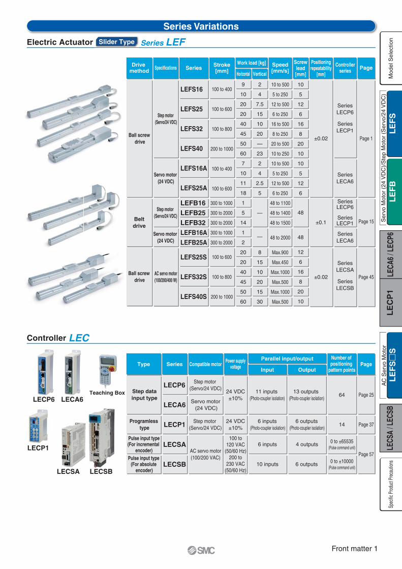
Series Variations
Specifications
Step motor (Servo/24 VDC)
Series
LEFS16
LEFS25
LEFS32
LEFS40
Stroke[mm]
100 to 400
100 to 600
100 to 800
200 to 1000
100 to 400
100 to 600
Horizontal
Work load [kg]
Vertical
Speed[mm/s]
Screwlead[mm]
10
5
12
6
16
8
20
10
10
5
12
6
Positioningrepeatability
[mm]
±0.02
±0.1
Controllerseries
SeriesLECP6
SeriesLECP1
Servo motor (24 VDC)
Drive method
Ball screw drive
LEFS16A
LEFS25A
Step motor (Servo/24 VDC)Belt
drive
SeriesLECA6
48
48
12
6
16
8
20
10
LEFB16LEFB25LEFB32
300 to 1000
300 to 2000
300 to 2000
Servo motor (24 VDC)
SeriesLECA6
SeriesLECP6
SeriesLECP1
LEFB16ALEFB25A
300 to 1000
300 to 2000
9
10
20
20
40
45
50
60
7
10
11
18
1
5
14
1
2
20
20
40
45
50
60
2
4
7.5
15
10
20
—
23
2
4
2.5
5
—
—
8
15
10
20
15
30
10 to 500
5 to 250
12 to 500
6 to 250
16 to 500
8 to 250
20 to 500
10 to 250
10 to 500
5 to 250
12 to 500
6 to 250
48 to 1100
48 to 1400
48 to 1500
48 to 2000
Max.900
Max.450
Max.1000
Max.500
Max.1000
Max.500
Page
Page 1
Page 15
AC servo motor(100/200/400 W)
LEFS25S
LEFS32S
LEFS40S
100 to 600
100 to 800
200 to 1000
±0.02
SeriesLECSA
SeriesLECSB
Ball screw drive Page 45
Page
Page 25
Page 57
LECP6 LECA6Teaching Box
Type
Step data input type
Controller LEC
Series
LECP6
LECA6
Compatible motor
Step motor (Servo/24 VDC)
Servo motor (24 VDC)
Power supplyvoltage
24 VDC±10%
Input
Parallel input/output
11 inputs (Photo-coupler isolation)
Output
13 outputs (Photo-coupler isolation)
Number ofpositioning
pattern points
64
Programless type LECP1 Step motor
(Servo/24 VDC)24 VDC±10%
6 inputs (Photo-coupler isolation)
6 outputs (Photo-coupler isolation)
14 Page 37
Pulse input type(For incremental
encoder)LECSA 6 inputs 4 outputs 0 to ±65535
(Pulse command unit)
Pulse input type(For absolute
encoder)LECSB
AC servo motor(100/200 VAC)
100 to120 VAC
(50/60 Hz)200 to
230 VAC(50/60 Hz)
10 inputs 6 outputs 0 to ±10000(Pulse command unit)
Slider Type
LECP1
LECSA LECSB
Ser
vo M
otor
(24
VD
C)/
Ste
p M
otor
(S
ervo
/24
VD
C)
Mod
el S
elec
tion
Spec
ific P
roduc
t Prec
autio
nsA
C S
ervo
Mot
or
Front matter 1

Front matter 2
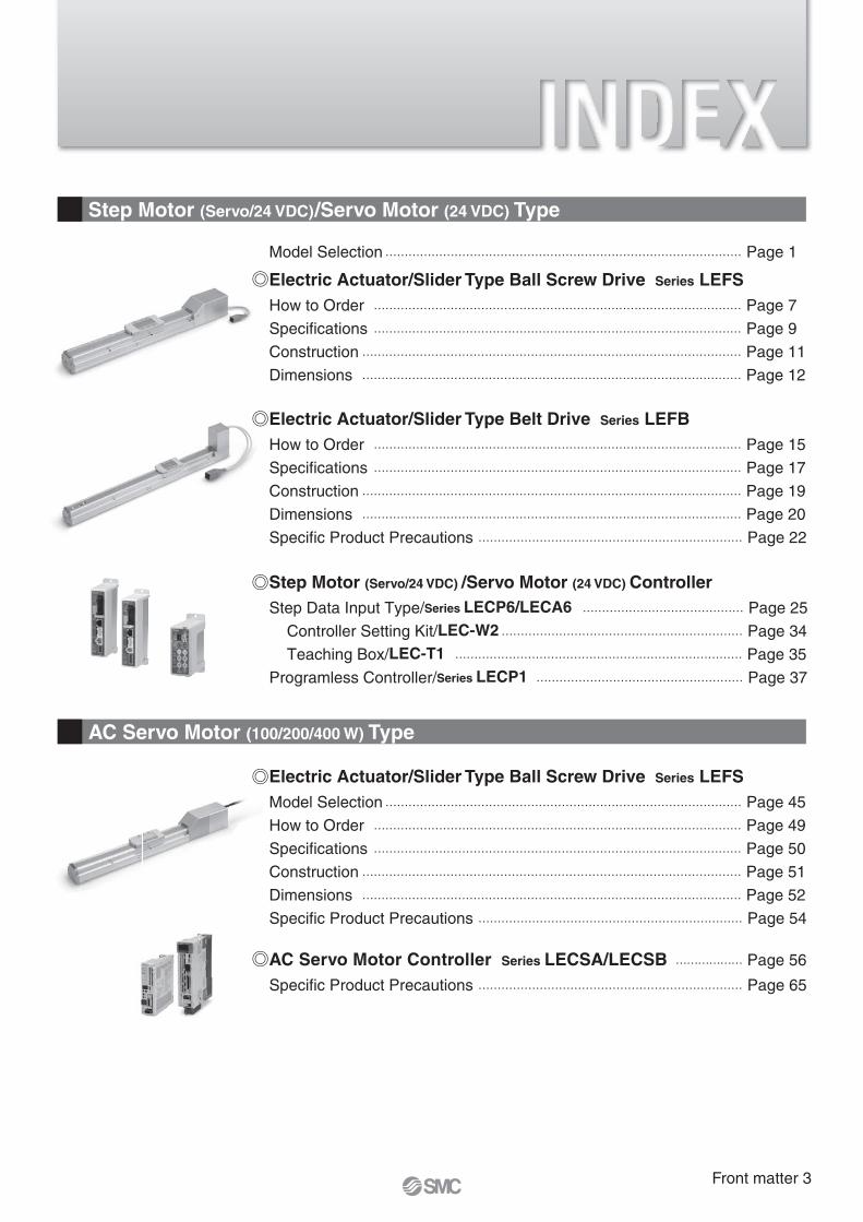
Step Motor (Servo/24 VDC)/Servo Motor (24 VDC) Type
Electric Actuator/Slider Type Ball Screw Drive Series LEFS How to Order …………………………………………………………………………………… Page 7
Specifications …………………………………………………………………………………… Page 9
Construction ……………………………………………………………………………………… Page 11
Dimensions ……………………………………………………………………………………… Page 12
Model Selection ………………………………………………………………………………… Page 1
Electric Actuator/Slider Type Belt Drive Series LEFBHow to Order …………………………………………………………………………………… Page 15
Specifications …………………………………………………………………………………… Page 17
Construction ……………………………………………………………………………………… Page 19
Dimensions ……………………………………………………………………………………… Page 20
Specific Product Precautions …………………………………………………………… Page 22
Step Motor (Servo/24 VDC) /Servo Motor (24 VDC) ControllerStep Data Input Type/Series LECP6/LECA6 …………………………………… Page 25
Controller Setting Kit/LEC-W2 ……………………………………………………… Page 34
Teaching Box/LEC-T1 ………………………………………………………………… Page 35
Programless Controller/Series LECP1 ……………………………………………… Page 37
AC Servo Motor (100/200/400 W) Type
Electric Actuator/Slider Type Ball Screw Drive Series LEFS Model Selection ………………………………………………………………………………… Page 45
How to Order …………………………………………………………………………………… Page 49
Specifications …………………………………………………………………………………… Page 50
Construction ……………………………………………………………………………………… Page 51
Dimensions ……………………………………………………………………………………… Page 52
Specific Product Precautions …………………………………………………………… Page 54
AC Servo Motor Controller Series LECSA/LECSB ……………… Page 56
Specific Product Precautions …………………………………………………………… Page 65
Front matter 3

Hor
izon
tal w
ork
load
: W [k
g]
Speed: V [mm/s]
20
15
10
5
00 300200 400100 500 600 700
2,000
1,500
1,000
500
00 5 10 15 20Workpiece mass [kg]
Ove
rhan
g L
1 [m
m]
L1
Mep
m
T1
a1 a2
LS
peed
: V [m
m/s
]
Time[s]
T2 T3 T4
Selection Procedure
Selection Example
Step 1 Confirm the work load – speed.
Step 2 Confirm the cycle time. Step 3 Confirm the allowable moment.
100
W2]
Operatingconditions
<Speed–Work load graph>(LEFS25/Step motor)
Lead 12: LEFS25A
Lead 6: LEFS25B
Step 1 Confirmation of work load–speed <Speed–Work load graph> (Pages 2 and 3)
Select the target model based on the workpiece mass and speed with reference to the (Speed–Work load graph).Selection example) The LEFS25A-200 is temporarily selected based on the graph shown on the right side.
Step 2 Confirmation of cycle time
Cycle time:
T = T1 + T2 + T3 + T4 [s]
T1 = V/a1 [s] T3 = V/a2 [s]
T2 = [s]L – 0.5 · V · (T1 + T3)
V
� T4:Settling time varies depending on
load and in positioning of the step
the settling time with reference to
� T2:
� T1:-
eration time can be obtained by the
Step 3 Confirmation of guide moment
Based on the above calculation result, the LEFS25A-200 is selected.
5000 mm/s2
3000 mm/s2
1000 mm/s2
L : Stroke [mm] ··· (Operating condition)
V : Speed [mm/s] ··· (Operating condition)
2] ··· (Operating condition)
2] ··· (Operating condition)
T2 : Constant speed time [s]
operating at a constant speed
Time from the beginning of the constant speed operation to stop
T4: Settling time [s]
T1 = V/a1 = 300/3000 = 0.1 [s],
T3 = V/a2 = 300/3000 = 0.1 [s]
T4 = 0.2 [s]
Therefore, the cycle time can be obtained as follows.
T = T1 + T2 + T3 + T4
= 0.1 + 0.57 + 0.1 + 0.2
= 0.97 [s]
T2 =
=
= 0.57 [s]
L – 0.5 · V · (T1 + T3)
V
200 – 0.5 · 300 · (0.1 + 0.1)
300
T4 = 0.2 [s]
Electric Actuator/Slider Type
Ball Screw Drive/Series LEFS Belt Drive/Series LEFB Model Selection
1

Hor
izon
tal w
ork
load
: W [k
g]
Speed: V [mm/s]0 100 200 300 400 500 600
12
10
8
6
4
2
0
Ver
tical
wor
k lo
ad: W
[kg]
Speed: V [mm/s]0 100 200 300 400 500 600
12
10
8
6
4
2
0
Hor
izon
tal w
ork
load
: W [k
g]
Speed: V [mm/s]0 100 200 300 400 500 600
50
40
30
20
10
00 100 200 300 400 500 600
50
40
30
20
10
0
Ver
tical
wor
k lo
ad: W
[kg]
Speed: V [mm/s]
Hor
izon
tal w
ork
load
: W [k
g]
Speed: V [mm/s]0 100 200 300 400 500 600
20
15
10
5
00 100 200 300 400 500 600
20
15
10
5
0
Ver
tical
wor
k lo
ad: W
[kg]
Speed: V [mm/s]
Speed–Work Load Graph (Guide)Step Motor (Servo/24 VDC)
LEFS16/Ball Screw Drive
LEFS32/Ball Screw Drive
LEFS25/Ball Screw Drive
∗ The following graph shows the values when positioning force is 100%.
Horizontal
Lead 5: LEFS16B
Lead 10: LEFS16A
Vertical
Lead 5: LEFS16B
Lead 10: LEFS16A
Horizontal
Lead 8: LEFS32B
Lead 16: LEFS32A Lead 8: LEFS32B
Lead 16: LEFS32A
Vertical
Horizontal
Lead 6: LEFS25B
Lead 12: LEFS25A
Vertical
Lead 6: LEFS25B
Lead 12: LEFS25A
Vertical
LEFS40/Ball Screw Drive
Horizontal
0
10
20
30
40
50
60
0 100 200 300 400 500 600
Hor
izon
tal w
ork
load
: W [k
g]
Speed: V [mm/s]
Lead 10
Lead 20
0
10
20
30
40
50
60
0 100 200 300 400 500 600
Ver
tical
wor
k lo
ad: W
[kg]
Speed: V [mm/s]
Lead 10
Model Selection Series LEF
Ser
vo M
otor
(24
VD
C)/
Ste
p M
otor
(S
ervo
/24
VD
C)
Mod
el S
elec
tion
Spec
ific P
roduc
t Prec
autio
nsA
C S
ervo
Mot
or
2

Hor
izon
tal w
ork
load
: W [k
g]
Speed: V [mm/s]
0 100 200 300 400 500 600 700 800 900
12
10
8
6
4
2
0
Ver
tical
wor
k lo
ad: W
[kg]
Speed: V [mm/s]
0 100 200 300 400 500 600 700 800 900
12
10
8
6
4
2
0
Hor
izon
tal w
ork
load
: W [k
g]
Speed: V [mm/s]
0 100 200 300 400 500 600 700 800 900
20
15
10
5
0
Ver
tical
wor
k lo
ad: W
[kg]
Speed: V [mm/s]
Hor
izon
tal w
ork
load
: W [k
g]
Speed: V [mm/s]
0 500 1000 1500 2000
14
12
10
8
6
4
2
0
0 100 200 300 400 500 600 700 800 900
20
15
10
5
0
Hor
izon
tal w
ork
load
: W [k
g]
Speed: V [mm/s]
0 500 1000 1500 2000
10
8
6
4
2
0
Speed–Work Load Graph (Guide)Servo Motor (24 VDC)
LEFS16A/Ball Screw Drive
LEFB/Belt Drive
LEFS25A/Ball Screw Drive
∗ The following graph shows the values when positioning force is 250%.
∗ When positioning force is 250%∗ When positioning force is 100%
Step Motor (Servo/24 VDC)
LEFB/Belt Drive
Servo Motor (24 VDC)
Horizontal
Horizontal
Horizontal
Vertical
Vertical
Horizontal
Lead 5: LEFS16AB
Lead 10: LEFS16AA
Lead 5: LEFS16AB
Lead 10: LEFS16AA
Lead 6: LEFS25AB
Lead 12: LEFS25AA
Lead 6: LEFS25AB
Lead 12: LEFS25AA
LEFB32
LEFB25
LEFB16
LEFB25
LEFB16
Series LEF
3

Workpiece mass [kg]
Ove
rhan
g L
5 [m
m]
1,500
1,000
500
0
Workpiece mass [kg]
Ove
rhan
g L
4 [m
m]
1,500
1,000
500
0
0Workpiece mass [kg]
Ove
rhan
g L
3 [m
m]
1,500
1,000
500
0605040302010
0Workpiece mass [kg]
Ove
rhan
g L
2 [m
m]
1,500
1,000
500
0605040302010
0Workpiece mass [kg]
Ove
rhan
g L
1 [m
m]
1,500
1,000
500
0605040302010
0 252015105
0 252015105
Dynamic Allowable Moment
Model
LEF16 LEF25 LEF32 LEFS40
2,000
1,500
1,000
500
00 2 4 6 8 10
Workpiece mass [kg]
Ove
rhan
g L
1 [m
m]
2,000
1,500
1,000
500
00 5 10 15 20
Workpiece mass [kg]O
verh
ang
L1
[mm
]
2,000
1,500
1,000
500
00 10 20 30 40
Workpiece mass [kg]
Ove
rhan
g L
1 [m
m]
5 10 15 20
5 10 15 20
5 10 15
2,000
1,500
1,000
500
00 2 4 6 8 10
Workpiece mass [kg]
Ove
rhan
g L
2 [m
m]
2,000
1,500
1,000
500
00
Workpiece mass [kg]
Ove
rhan
g L
2 [m
m]
2,000
1,500
1,000
500
00
Workpiece mass [kg]
Ove
rhan
g L
2 [m
m]
2,000
1,500
1,000
500
00 2 4 6 8 10
Workpiece mass [kg]
Ove
rhan
g L
3 [m
m]
2,000
1,500
1,000
500
00
Workpiece mass [kg]
Ove
rhan
g L
3 [m
m]
2,000
1,500
1,000
500
00
Workpiece mass [kg]
Ove
rhan
g L
3 [m
m]
2,000
1,500
1,000
500
00 1 2 3 4 5
Workpiece mass [kg]
Ove
rhan
g L
4 [m
m]
2,000
1,500
1,000
500
00 5 10 15
Workpiece mass [kg]
Ove
rhan
g L
4 [m
m]
2,000
1,500
1,000
500
00 20
5 10 15 20
Workpiece mass [kg]
Ove
rhan
g L
4 [m
m]
2,000
1,500
1,000
500
00 1 2 3 4 5
Workpiece mass [kg]
Ove
rhan
g L
5 [m
m]
2,000
1,500
1,000
500
00 5 10 15
Workpiece mass [kg]
Ove
rhan
g L
5 [m
m]
2,000
1,500
1,000
500
00
Workpiece mass [kg]
Ove
rhan
g L
5 [m
m]
L1
L2
10 20 30 40
10 20 30 40
Mep
m
Mey
m
L3
Merm
L4
Mepm
L5
Meym
Acceleration 1000 mm/s2 3000 mm/s2 5000 mm/s2
Orie
ntat
ion Load overhanging direction
m : Work load [kg]Me : Dynamic allowable moment [N·m]L : Amount of overhang to the centre of gravity of the workpiece [mm]
Ver
tica
lH
ori
zon
tal
Pit
chin
gP
itch
ing
Yaw
ing
Yaw
ing
Ro
llin
g
Model Selection Series LEF
Ser
vo M
otor
(24
VD
C)/
Ste
p M
otor
(S
ervo
/24
VD
C)
Mod
el S
elec
tion
Spec
ific P
roduc
t Prec
autio
nsA
C S
ervo
Mot
or
∗ This graph shows the amount of allowable overhang when the centre of gravity of the workpiece overhangsin one direction. When the centre of gravity of the workpiece overhangs in two directions, refer to the ElectricActuator Selection Software for confirmation. http://www.smcworld.com
4

0.08
0.06
0.04
0.02
00 100 200 300 400 500
Dis
plac
emen
t [m
m]
Load W [N]
w
q
A side
C side
B side
D side
WL
LEF32(l = 30 mm)
Table Accuracy
LEF16LEF25LEF32LEF40
Model
Note) Traveling parallelism does not include the mounting surface accuracy.
Note) This displacement is measured when a 15 mm aluminum plate is mounted and fixed on the table.
0.05
0.05
0.05
0.05
0.03
0.03
0.03
0.03
q C side travelingparallelism to A side
Traveling parallelism [mm] (Every 300 mm)
w D side travelingparallelism to B side
Table Displacement (Reference Value)
LEF16(L = 20 mm)
LEF25(L = 25 mm)
LEF32(L = 30 mm)
LEF40(L = 37 mm)
Series LEF
5

Ser
vo M
otor
(24
VD
C)/
Ste
p M
otor
(S
ervo
/24
VD
C)
Mod
el S
elec
tion
Spec
ific P
roduc
t Prec
autio
nsA
C S
ervo
Mot
or
6
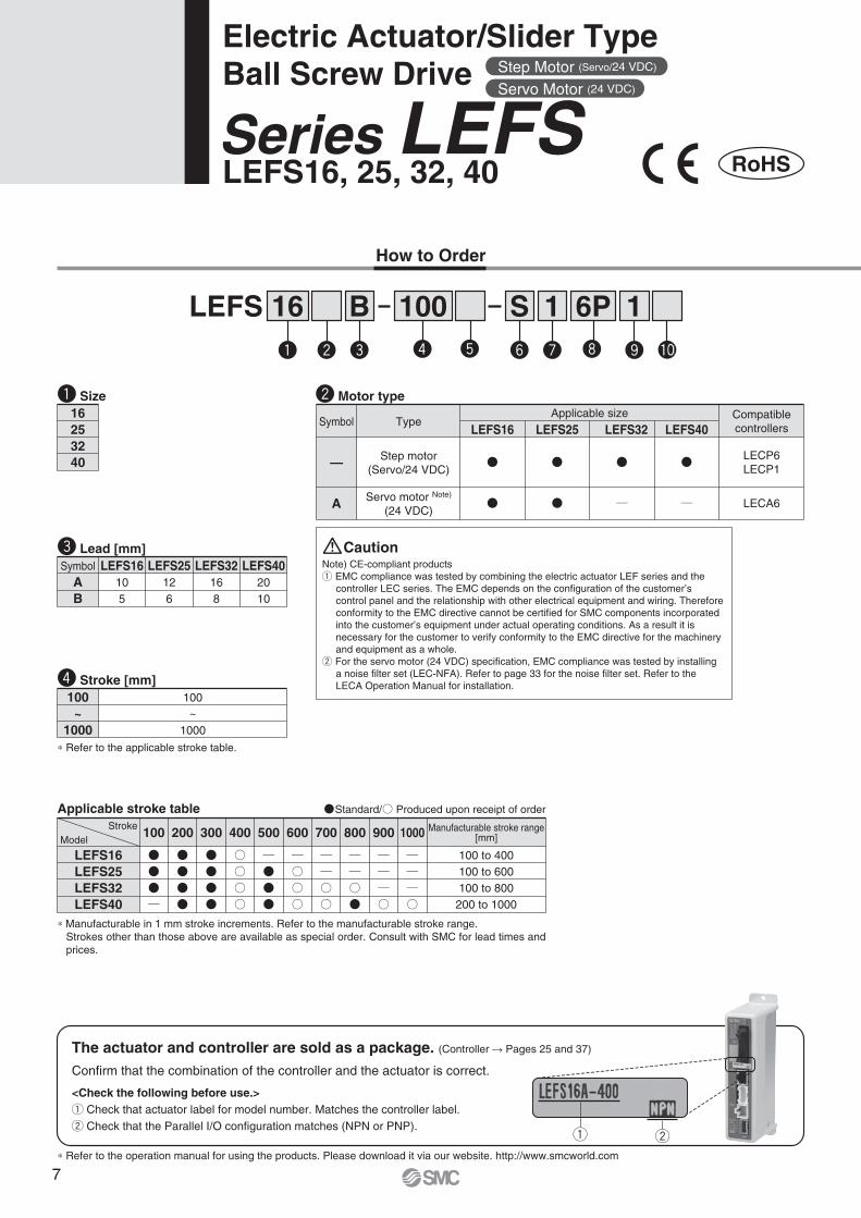
LEFS 16 100B 11S 6P
Applicable stroke table
LEFS16LEFS25LEFS32LEFS40
100 200 300 400 500 600 800 900
100 to 400100 to 600100 to 800200 to 1000
1000700
Standard/ Produced upon receipt of order
How to Order
LEFS16, 25, 32, 40Series LEFSElectric Actuator/Slider TypeBall Screw Drive
—
AB
LEFS16105
LEFS25126
LEFS32168
LEFS402010
Symbol
100
1000
∗ Refer to the applicable stroke table.
100
1000
Stroke Manufacturable stroke range[mm]Model
Confirm that the combination of the controller and the actuator is correct.
The actuator and controller are sold as a package. (Controller � Pages 25 and 37)
<Check the following before use.>q Check that actuator label for model number. Matches the controller label.w Check that the Parallel I/O configuration matches (NPN or PNP).
∗ Refer to the operation manual for using the products. Please download it via our website. http://www.smcworld.com
q w
Symbol TypeApplicable size Compatible
controllers
LECP6LECP1
LECA6
Step motor(Servo/24 VDC)
Servo motor Note)
(24 VDC)
LEFS16 LEFS25 LEFS32
A
LEFS40
Note) CE-compliant productsq EMC compliance was tested by combining the electric actuator LEF series and the
controller LEC series. The EMC depends on the configuration of the customer’s control panel and the relationship with other electrical equipment and wiring. Therefore conformity to the EMC directive cannot be certified for SMC components incorporated into the customer’s equipment under actual operating conditions. As a result it is necessary for the customer to verify conformity to the EMC directive for the machinery and equipment as a whole.
w For the servo motor (24 VDC) specification, EMC compliance was tested by installing a noise filter set (LEC-NFA). Refer to page 33 for the noise filter set. Refer to the LECA Operation Manual for installation.
q w e r t y u i o !0
16253240
q Size w Motor type
e Lead [mm]
r Stroke [mm]
∗ Manufacturable in 1 mm stroke increments. Refer to the manufacturable stroke range.Strokes other than those above are available as special order. Consult with SMC for lead times and prices.
RoHS
Caution
Step Motor (Servo/24 VDC)
Servo Motor (24 VDC)
~ ~
7
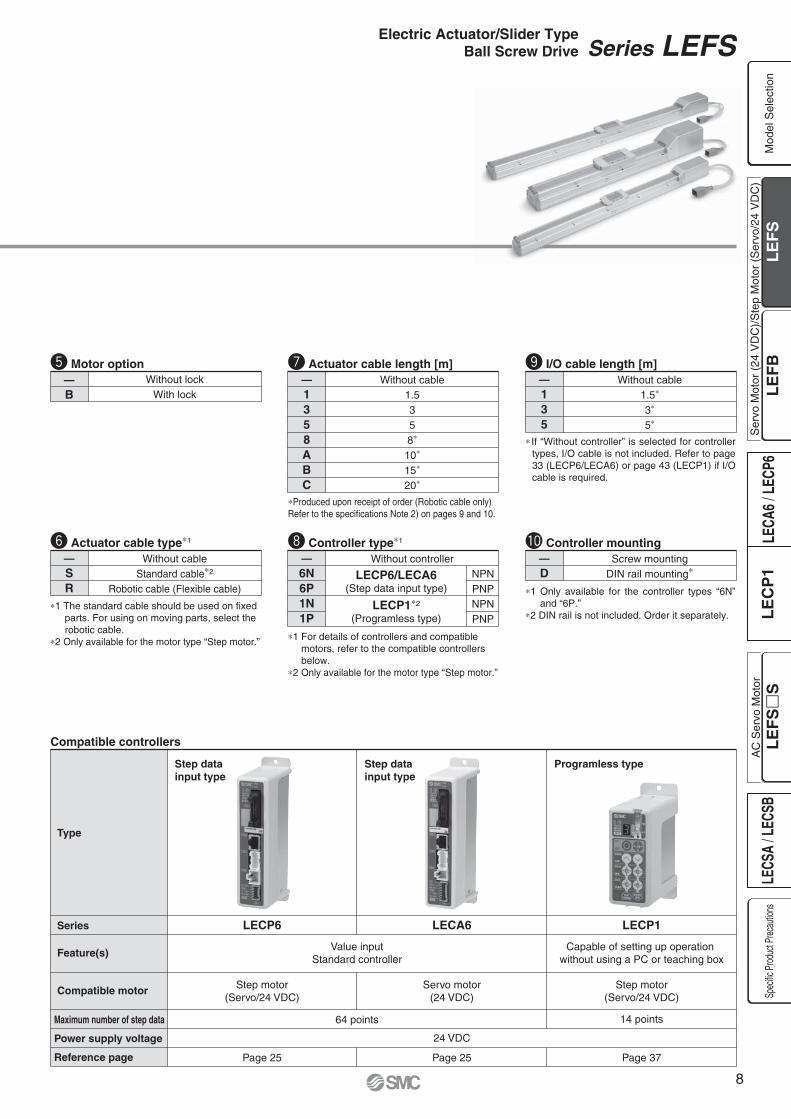
Compatible controllers
Type
Series
Feature(s)
Compatible motor
LECP6 LECA6
24 VDC
Value inputStandard controller
64 points
LECP1
Step motor(Servo/24 VDC)
Servo motor(24 VDC)
Step motor(Servo/24 VDC)
14 points
Capable of setting up operation without using a PC or teaching box
Page 25 Page 25 Page 37
Step datainput type
Step datainput type
Programless type
Maximum number of step data
Power supply voltage
Reference page
—1358ABC
Without cable1.5358∗
10∗
15∗
20∗
∗Produced upon receipt of order (Robotic cable only) Refer to the specifications Note 2) on pages 9 and 10.
—B
Without lockWith lock
—D
Screw mountingDIN rail mounting∗
—135
Without cable1.5∗
3∗
5∗
t Motor option u Actuator cable length [m] o I/O cable length [m]
!0 Controller mounting —6N6P1N1P
Without controller
∗1 For details of controllers and compatible motors, refer to the compatible controllers below.
∗2 Only available for the motor type “Step motor.”
∗1 Only available for the controller types “6N” and “6P.”
∗2 DIN rail is not included. Order it separately.
∗ If “Without controller” is selected for controller types, I/O cable is not included. Refer to page 33 (LECP6/LECA6) or page 43 (LECP1) if I/O cable is required.
i Controller type∗1
NPNPNPNPNPNP
LECP1∗2
(Programless type)
LECP6/LECA6(Step data input type)
—SR
Without cableStandard cable∗2
Robotic cable (Flexible cable)
y Actuator cable type∗1
∗1 The standard cable should be used on fixed parts. For using on moving parts, select the robotic cable.
∗2 Only available for the motor type “Step motor.”
Series LEFSElectric Actuator/Slider TypeBall Screw Drive
Ser
vo M
otor
(24
VD
C)/
Ste
p M
otor
(S
ervo
/24
VD
C)
Mod
el S
elec
tion
Spec
ific P
roduc
t Prec
autio
nsA
C S
ervo
Mot
or
8
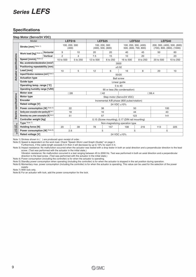
Specifications
Note 1) Strokes shown in ( ) are produced upon receipt of order.Note 2) Speed is dependent on the work load. Check “Speed–Work Load Graph (Guide)” on page 2. Furthermore, if the cable length exceeds 5 m then it will decrease by up to 10% for each 5 m.Note 3) Impact resistance: No malfunction occurred when the actuator was tested with a drop tester in both an axial direction and a perpendicular direction to the lead
screw. (Test was performed with the actuator in the initial state.)Vibration resistance: No malfunction occurred in a test ranging between 45 to 2000 Hz. Test was performed in both an axial direction and a perpendicular direction to the lead screw. (Test was performed with the actuator in the initial state.)
Note 4) Power consumption (including the controller) is for when the actuator is operating.Note 5) Standby power consumption when operating (including the controller) is for when the actuator is stopped in the set position during operation.Note 6) Momentary max. power consumption (including the controller) is for when the actuator is operating. This value can be used for the selection of the power
supply.Note 7) With lock only.Note 8) For an actuator with lock, add the power consumption for the lock.
100, 200, 300(400)
�28
22
18
51
�42
38
16
57
�56.4
50
44
123
100
43
141
9
2
10 to 500
10
3000
±0.02
50/20
Ball screw
Linear guide
5 to 40
90 or less (No condensation)
Step motor (Servo/24 VDC)
Incremental A/B phase (800 pulse/rotation)
24 VDC ±10%
0.15 (Screw mounting), 0.17 (DIN rail mounting)
Non-magnetizing operation type
24 VDC ±10%
10
4
5 to 250
5
100, 200, 300(400), 500, (600)
100, 200, 300, (400)500, (600, 700, 800)
Step Motor (Servo/24 VDC)
2.9
20 39 78 157 108 216 113 225
5 5 5
Model LEFS16 LEFS25 LEFS32
Act
uat
or
spec
ific
atio
ns
Ele
ctri
c sp
ecif
icat
ion
sL
ock
un
itsp
ecif
icat
ion
s
Stroke [mm] Note 1)
Work load [kg] Note 2)
Speed [mm/s] Note 2)
Max. acceleration/deceleration [mm/s2]
Positioning repeatability [mm]
Lead [mm]
Impact/Vibration resistance [m/s2] Note 3)
Actuation type
Guide type
Operating temp. range [°C]
Operating humidity range [%RH]
Motor size
Motor type
Encoder
Rated voltage [V]
Power consumption [W] Note 4)
Standby power consumption when operating [W] Note 5)
Momentary max. power consumption [W] Note 6)
Controller weight [kg]
Type Note 7)
Holding force [N]
Power consumption [W] Note 8)
Rated voltage [V]
20
7.5
12 to 500
12
20
15
6 to 250
6
40
10
16 to 500
16
45
20
8 to 250
8
200, 300, (400), 500, (600)(700), 800, (900), (1000)
LEFS40
50
20 to 500
20
60
23
10 to 250
10
Horizontal
Vertical
Series LEFS
9

Note 1) Strokes shown in ( ) are produced upon receipt of order.Note 2) Check “Speed–Work Load Graph (Guide)” on page 3.
Furthermore, if the cable length exceeds 5 m then it will decrease by up to 10% for each 5 m.Note 3) Impact resistance: No malfunction occurred when the actuator was tested with a drop tester in both an axial direction and a perpendicular direction to the lead
screw. (Test was performed with the actuator in the initial state.)Vibration resistance: No malfunction occurred in a test ranging between 45 to 2000 Hz. Test was performed in both an axial direction and a perpendicular direction to the lead screw. (Test was performed with the actuator in the initial state.)
Note 4) Power consumption (including the controller) is for when the actuator is operating.Note 5) Standby power consumption when operating (including the controller) is for when the actuator is stopped in the set position during operation.Note 6) Momentary max. power consumption (including the controller) is for when the actuator is operating. This value can be used for the selection of the power
supply.Note 7) With lock only.Note 8) For an actuator with lock, add the power consumption for the lock.
100, 200, 300(400)
�28
30
63
Horizontal 4/Vertical 9
70
�42
36
102
Horizontal 4/Vertical 9
113
7
2
10 to 500
10
3000
±0.02
50/20
Ball screw
Linear guide
5 to 40
90 or less (No condensation)
Servo motor (24 VDC)
Incremental A/B (800 pulse/rotation)/Z phase
24 VDC ±10%
0.15 (Screw mounting), 0.17 (DIN rail mounting)
Non-magnetizing operation type
24 VDC ±10%
10
4
5 to 250
5
100, 200, 300(400), 500, (600)
Servo Motor (24 VDC)
2.9
20 39 78 157
5
Model LEFS16A LEFS25A
Act
uat
or
spec
ific
atio
ns
Ele
ctri
c sp
ecif
icat
ion
sL
ock
un
itsp
ecif
icat
ion
s
Stroke [mm] Note 1)
Work load [kg] Note 2)
Speed [mm/s] Note 2)
Max. acceleration/deceleration [mm/s2]
Positioning repeatability [mm]
Lead [mm]
Impact/Vibration resistance [m/s2] Note 3)
Actuation type
Guide type
Operating temp. range [°C]
Operating humidity range [%RH]
Motor size
Motor output [W]
Motor type
Encoder
Rated voltage [V]
Power consumption [W] Note 4)
Standby power consumption when operating [W] Note 5)
Momentary max. power consumption [W] Note 6)
Controller weight [kg]
Type Note 7)
Holding force [N]
Power consumption [W] Note 8)
Rated voltage [V]
11
2.5
12 to 500
12
18
5
6 to 250
6
Horizontal
Vertical
Specifications
Weight
0.53
Model LEFS32Stroke [mm]
Product weight [kg]
Additional weight with lock [kg]
100
3.35
200
3.75
300
4.15
500
4.95
(800)
6.15
(700)
5.75
(600)
5.35
(400)
4.55
0.12
Model LEFS16Stroke [mm]
Product weight [kg]
Additional weight with lock [kg]
100
0.90
200
1.05
300
1.20
(400)
1.35
Model
Stroke [mm]
Product weight [kg]
Additional weight with lock [kg]
LEFS40200
5.65
300
6.21
500
7.33
(400)
6.77
800
9.01
(900)
9.57
(1000)
10.13
(700)
8.45
(600)
7.89
0.53
Model
Stroke [mm]
Product weight [kg]
Additional weight with lock [kg]
100
1.84
(400)
2.68
300
2.40
200
2.12
LEFS25500
2.96
(600)
3.24
0.26
Electric Actuator/Slider TypeBall Screw Drive Series LEFS
Ser
vo M
otor
(24
VD
C)/
Ste
p M
otor
(S
ervo
/24
VD
C)
Mod
el S
elec
tion
Spec
ific P
roduc
t Prec
autio
nsA
C S
ervo
Mot
or
10

A
A
A-A
q t y uu o !1 !3!7!7 !8
e r !0 !2 !5@0 @0@1 @1@2 @3 i!4!6
w!9
A
A
No. Description Material Note
1
2
3
4
5
6
7
8
9
10
11
Body
Rail guide
Ball screw assembly
Connected shaft
Spacer
Table
Blanking plate
Seal band stopper
Housing A
Housing B
Bearing stopper
Motor mount
Aluminium alloy
—
—
—
Aluminium alloy
Aluminium alloy
Synthetic resin
Aluminium die-casted
Aluminium alloy
Aluminium alloy
Aluminium alloy
Anodised
Anodised
Anodised
Coating
Coating
Coating
No. Description Material Note
12
13
14
15
16
17
18
19
20
21
22
23
Coupling
Motor cover
End cover
Motor
Rubber bushing
Band stopper
Dust seal band
Seal magnet
Roller shaft
Wiper
Bearing
Bearing
—
Aluminium alloy
Aluminium alloy
—
NBR
Stainless steel
Stainless steel
—
Aluminium alloy
—
—
—
Anodised
Anodised
Construction
LEFS16, 25, 32
LEFS40
!7 !8 q
@2 e r @3 !0 !2 !5!6 !4
u t y u !7 o !1 !3
i
w
A-A
LEFS16, 25, 32
LEFS40
Series LEFS
11
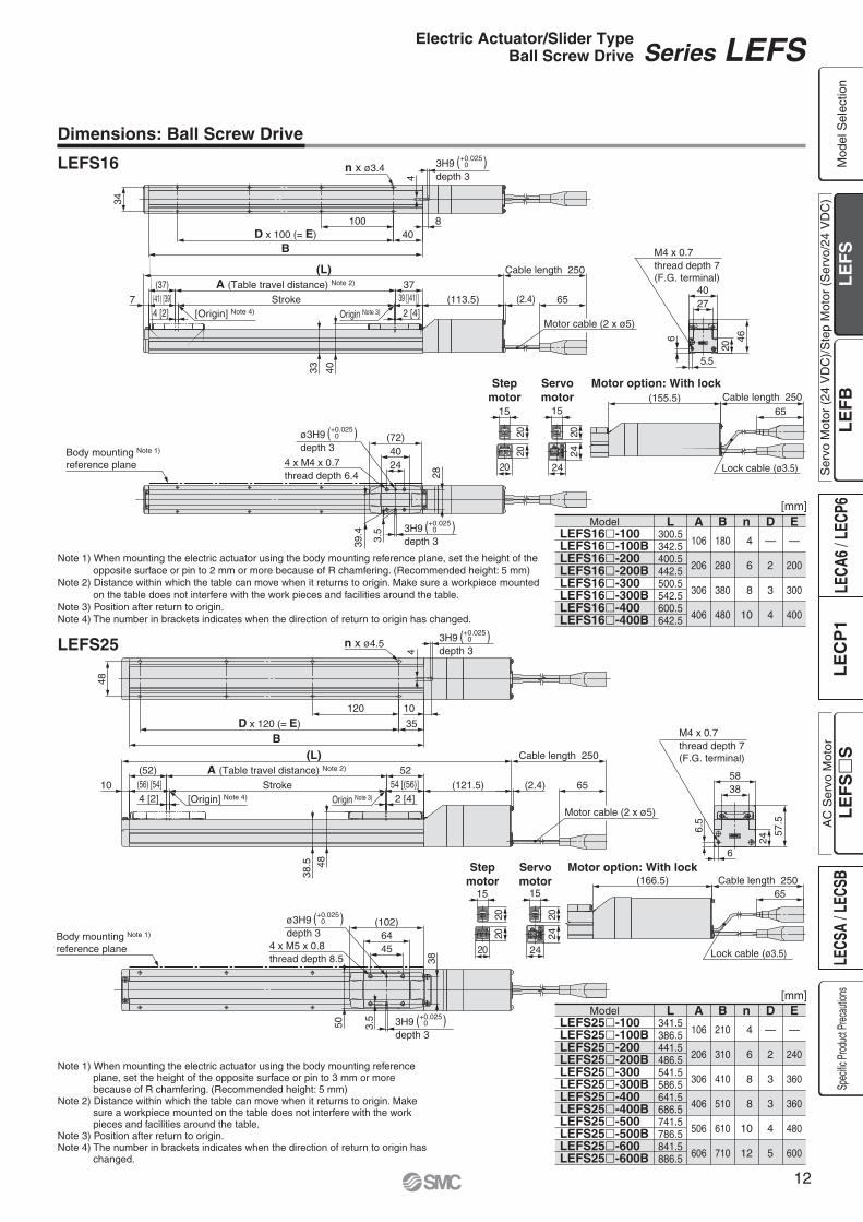
Dimensions: Ball Screw Drive
20
46
2740
28
2440
(72)
4 x M4 x 0.7thread depth 6.4
3.5
39.4
40100
D x 100 (= E)
34
B
n x ø3.4
(155.5)65
Cable length 250
2020
15
20 Lock cable (ø3.5)
Motor option: With lock
24
57.5
3858
4564
(102)
50
38
3.5
4 x M5 x 0.8thread depth 8.5
35
120
D x 120 (= E)
B
48
n x ø4.5
(166.5) Cable length 25065
2020
15
20 Lock cable (ø3.5)
Motor option: With lock
Stepmotor
Servomotor
20
15
24
24
Stepmotor
Servomotor
20
15
24
24
403365
Cable length 250
Motor cable (2 x ø5)48
38.5
Cable length 250
65
Motor cable (2 x ø5)
(L)
(L)
ø3H9depth 3
( ) +0.0250
ø3H9depth 3
( ) +0.0250
Body mounting Note 1)
reference plane
Body mounting Note 1)
reference plane
6
5.5
M4 x 0.7thread depth 7(F.G. terminal)
M4 x 0.7thread depth 7(F.G. terminal)
8
4
6.5
6
10
4
(41) [39] 39 [(41)]Stroke4 [2] 2 [4]
(2.4)7
(37) A (Table travel distance) Note 2)
(113.5)
37
[Origin] Note 4) Origin Note 3)
54 [(56)](56) [54] Stroke4 [2]
(52) A (Table travel distance) Note 2)
2 [4]10
52
(121.5) (2.4)[Origin] Note 4) Origin Note 3)
3H9depth 3
( ) +0.0250
( ) 3H9depth 3
+0.0250
3H9depth 3
( ) +0.0250
( ) 3H9depth 3
+0.0250
LEFS16
LEFS25
Note 1) When mounting the electric actuator using the body mounting reference plane, set the height of the opposite surface or pin to 2 mm or more because of R chamfering. (Recommended height: 5 mm)
Note 2) Distance within which the table can move when it returns to origin. Make sure a workpiece mounted on the table does not interfere with the work pieces and facilities around the table.
Note 3) Position after return to origin.Note 4) The number in brackets indicates when the direction of return to origin has changed.
Note 1) When mounting the electric actuator using the body mounting reference plane, set the height of the opposite surface or pin to 3 mm or more because of R chamfering. (Recommended height: 5 mm)
Note 2) Distance within which the table can move when it returns to origin. Make sure a workpiece mounted on the table does not interfere with the work pieces and facilities around the table.
Note 3) Position after return to origin.Note 4) The number in brackets indicates when the direction of return to origin has
changed.
LEFS16�-100LEFS16�-100BLEFS16�-200LEFS16�-200BLEFS16�-300LEFS16�-300BLEFS16�-400LEFS16�-400B
Model L300.5342.5400.5442.5500.5542.5600.5642.5
A
180
280
380
480
106
206
306
406
B
4
6
8
10
n
—
2
3
4
D
—
200
300
400
E
LEFS25�-100LEFS25�-100BLEFS25�-200LEFS25�-200BLEFS25�-300LEFS25�-300BLEFS25�-400LEFS25�-400BLEFS25�-500LEFS25�-500BLEFS25�-600LEFS25�-600B
Model L341.5386.5441.5486.5541.5586.5641.5686.5741.5786.5841.5886.5
A
210
310
410
510
610
710
106
206
306
406
506
606
B
4
6
8
8
10
12
n
—
2
3
3
4
5
D
—
240
360
360
480
600
E
[mm]
[mm]
Series LEFSElectric Actuator/Slider TypeBall Screw Drive
Ser
vo M
otor
(24
VD
C)/
Ste
p M
otor
(S
ervo
/24
VD
C)
Mod
el S
elec
tion
Spec
ific P
roduc
t Prec
autio
nsA
C S
ervo
Mot
or
12

6046
.8
65
Cable length 250
4270
(122)
44
4 x M6 x 1thread depth 9.9
ø5H9depth 5
5H9depth 5
5.5
60
60
15
150
D x 150 (= E)
B
n x ø5.5
3079
48
70
65
Cable length 250(199.5)
20
20
15
20
Motor cable (2 x ø5)
Lock cable (ø3.5)
Motor option: With lockStep
motorServomotor
20
15
24
24
(L)
Body mounting Note 1)
reference plane 60106
7
74
58
60
150
B
76
n x ø6.6
15
7
31
61
90
67.5
8
8
Lock cable (ø3.3)Motor cable (2 x ø5)
65
Cable length 250
20
20
20
15
4 x M8 x 1.25thread depth 13
ø6H9depth 7
( )+0.030 0 (170)
6H9depth 7
( )+0.030 0
(219.5)
D x 150 (= E)
( )6H9depth 6
+0.030 0
Motor option: With lock
20
20
Motor cable (2 x ø5)
Cable length 250
Stroke
4[2]
(90) [88]
A (Table travel distance) Note 2)
2[4]
88[(90)] (3.1)
(86)
6853
.8
13
(L)
65
86(170.5)
[Origin] Note 4) Origin Note 3)
Body mounting Note 1)
reference plane
7.5
6.5
M4 x 0.7thread depth 8(F.G. terminal)
15
6
( )5H9depth 5
+0.030 0
( )+0.030 0
( )+0.030 0
(62) 62(66) [64] 64 [(66)]Stroke4[2] 2[4]
(2.4)10A (Table travel distance) Note 2)
(147.5)[Origin] Note 4) Origin Note 3)
M4 x 0.7thread depth 8(F.G. terminal)
Dimensions: Ball Screw Drive
LEFS32 Note 1) When mounting the electric actuator using the body mounting reference plane, set the height of the opposite surface or pin to 3 mm or more because of R chamfering. (Recommended height: 5 mm)
Note 2) Distance within which the table can move when it returns to origin. Make sure a workpiece mounted on the table does not interfere with the work pieces and facilities around the table.
Note 3) Position after return to origin.Note 4) The number in brackets indicates when the
direction of return to origin has changed.
LEFS40
[mm]
[mm]
Note 1) When mounting the electric actuator using the body mounting reference plane, set the height of the opposite surface or pin to 3 mm or more because of R chamfering. (Recommended height: 5 mm)
Note 2) Distance within which the table can move when it returns to origin. Make sure a workpiece mounted on the table does not interfere with the work pieces and facilities around the table.
Note 3) Position after return to origin.Note 4) The number in brackets indicates when the
direction of return to origin has changed.
LEFS32�-100LEFS32�-100BLEFS32�-200LEFS32�-200B
Model L 387.5 439.5 487.5 539.5
A
230
330
106
206
B
4
6
n
—
2
D
—
300
E
LEFS32�-300LEFS32�-300BLEFS32�-400LEFS32�-400BLEFS32�-500LEFS32�-500BLEFS32�-600LEFS32�-600BLEFS32�-700LEFS32�-700BLEFS32�-800LEFS32�-800B
Model L 587.5 639.5 687.5 739.5 787.5 839.5 887.5 939.5 987.51039.51087.51139.5
A
430
530
630
730
830
930
306
406
506
606
706
806
B
6
8
10
10
12
14
n
2
3
4
4
5
6
D
300
450
600
600
750
900
E
[mm]
LEFS40�-200LEFS40�-200BLEFS40�-300LEFS40�-300BLEFS40�-400LEFS40�-400B
Model L 561.5 610.5 661.5 710.5 761.5 810.5
A
378
478
578
206
306
406
B
6
6
8
n
2
2
3
D
300
300
450
E
LEFS40�-500LEFS40�-500BLEFS40�-600LEFS40�-600BLEFS40�-700LEFS40�-700BLEFS40�-800LEFS40�-800BLEFS40�-900LEFS40�-900BLEFS40�-1000LEFS40�-1000B
Model L 861.5 910.5 961.51010.51061.51110.51161.51210.51261.51310.51361.51410.5
A
678
778
878
978
1078
1178
506
606
706
806
906
1006
B
10
10
12
14
14
16
n
4
4
5
6
6
7
D
600
600
750
900
900
1050
E
[mm]
Series LEFS
13

Ser
vo M
otor
(24
VD
C)/
Ste
p M
otor
(S
ervo
/24
VD
C)
Mod
el S
elec
tion
Spec
ific P
roduc
t Prec
autio
nsA
C S
ervo
Mot
or
14

LEFB 16 500T 11R 6P
Applicable stroke table
∗ Strokes other than those above are available as a special order.
∗ Belt drive actuator cannot be used for vertically mounted applications.
LEFB16LEFB25LEFB32
500 800 1000
—
1500
—
1800600 700300 900
—
1200
—
2000
Standard/ Produced upon receipt of order
How to Order
LEFB16, 25, 32Series LEFBElectric Actuator/Slider TypeBelt Drive
StrokeModel
Confirm that the combination of the controller and the actuator is correct.
The actuator and controller are sold as a package. (Controller � Pages 25 and 37)
<Check the following before use.>q Check that actuator label for model number. Matches the controller label.w Check that the Parallel I/O configuration matches (NPN or PNP).
∗ Refer to the operation manual for using the products. Please download it via our website. http://www.smcworld.com
q w
Note) CE-compliant productsq EMC compliance was tested by combining the electric actuator LEF series
and the controller LEC series. The EMC depends on the configuration of the customer’s control panel and the relationship with other electrical equipment and wiring. Therefore conformity to the EMC directive cannot be certified for SMC components incorporated into the customer’s equipment under actual operating conditions. As a result it is necessary for the customer to verify conformity to the EMC directive for the machinery and equipment as a whole.
w For the servo motor (24 VDC) specification, EMC compliance was tested by installing a noise filter set (LEC-NFA). Refer to page 33 for the noise filter set. Refer to the LECA Operation Manual for installation.
q w e r t y u i o !0
162532
300
2000~
∗ Refer to the applicable stroke table.
~300
2000
q Size
T 48
e Equivalent lead [mm]
r Stroke [mm]
w Motor type
RoHS
Caution
— �
Symbol TypeApplicable size Compatible
controller
LECP6LECP1
LECA6
Step motor(Servo/24 VDC)
Servo motor Note)
(24 VDC)
LEFB16 LEFB25 LEFB32
A —
15
Compatible controllers
Type
Series
Feature(s)
Compatible motor
LECP6 LECA6
24 VDC
Value inputStandard controller
64 points
LECP1
Step motor(Servo/24 VDC)
Servo motor(24 VDC)
Step motor(Servo/24 VDC)
14 points
Capable of seting up operation without using a PC or teaching box
Page 25 Page 25 Page 37
Step datainput type
Step datainput type
Programless type
Maximum number of step data
Power supply voltage
Reference page
—B
Without lockWith lock
t Motor option
—1358ABC
Without cable1.5358∗
10∗
15∗
20∗
∗Produced upon receipt of order (Robotic cable only) Refer to the specifications Note 2) on pages 17 and 18.
—D
Screw mountingDIN rail mounting∗
—135
Without cable1.5∗
3∗
5∗
u Actuator cable length [m]
i Controller type∗1
o I/O cable length [m]
!0 Controller mounting
—6N6P1N1P
Without controller
∗1 For details of controllers and compatible motors, refer to the compatible controllers below.
∗2 Only available for the motor type “Step motor.”
NPNPNPNPNPNP
LECP1∗2
(Programless type)
LECP6/LECA6(Step data input type)
∗1 Only available for the controller types “6N” and “6P.”
∗2 DIN rail is not included. Order it separately.
∗ If “Without controller” is selected for controller types, I/O cable is not included. Refer to page 33 (LECP6/LECA6) or page 43 (LECP1) if I/O cable is required.
—SR
Without cableStandard cable∗2
Robotic cable (Flexible cable)
y Actuator cable type∗1
∗1 The standard cable should be used on fixed parts. For using on moving parts, select the robotic cable.
∗2 Only available for the motor type “Step motor.”
Series LEFBElectric Actuator/Slider TypeBelt Drive
Ser
vo M
otor
(24
VD
C)/
Ste
p M
otor
(S
ervo
/24
VD
C)
Mod
el S
elec
tion
Spec
ific P
roduc
t Prec
autio
nsA
C S
ervo
Mot
or
16

Specifications
Note 1) Strokes shown in ( ) are produced upon receipt of order.Note 2) Speed is dependent on the work load. Check “Speed–Work Load Graph (Guide)” on page 3.
Furthermore, if the cable length exceeds 5 m then it will decrease by up to 10% for each 5 m.Note 3) Impact resistance: No malfunction occurred when the actuator was tested with a drop tester in both an axial direction and a perpendicular direction to the lead
screw. (Test was performed with the actuator in the initial state.)Vibration resistance: No malfunction occurred in a test ranging between 45 to 2000 Hz. Test was performed in both an axial direction and a perpendicular direction to the lead screw. (Test was performed with the actuator in the initial state.)
Note 4) Power consumption (including the controller) is for when the actuator is operating.Note 5) Standby power consumption when operating (including the controller) is for when the actuator is stopped in the set position during operation.Note 6) Momentary max. power consumption (including the controller) is for when the actuator is operating. This value can be used for the selection of the power
supply.Note 7) With lock only.Note 8) For an actuator with lock, add the power consumption for the lock.
(300), 500, (600, 700)800, (900), 1000
�28
24
18
51
�42
32
16
60
�56.4
52
44
127
1
48 to 1100
48
3000
±0.1
50/20
Belt
Linear guide
5 to 40
90 or less (No condensation)
Step motor (Servo/24 VDC)
Incremental A/B phase (800 pulse/rotation)
24 VDC ±10%
0.15 (Screw mounting), 0.17 (DIN rail mounting)
Non-magnetizing operation type
24 VDC ±10%
(300), 500, (600, 700), 800, (900)1000, (1200, 1500, 1800, 2000)
(300), 500, (600, 700), 800, (900)1000, (1200, 1500, 1800, 2000)
Step Motor (Servo/24 VDC)Model LEFB16 LEFB25 LEFB32
Act
uat
or
spec
ific
atio
ns
Ele
ctri
c sp
ecif
icat
ion
sL
ock
un
itsp
ecif
icat
ion
s
Stroke [mm] Note 1)
Work load [kg] Note 2)
Speed [mm/s] Note 2)
Max. acceleration/deceleration [mm/s2]Positioning repeatability [mm]Equivalent lead [mm]Impact/Vibration resistance [m/s2] Note 3)
Actuation typeGuide typeOperating temp. range [°C]Operating humidity range [%RH]Motor sizeMotor typeEncoderRated voltage [V]Power consumption [W] Note 4)
Standby power consumption when operating [W] Note 5)
Momentary max. power consumption [W] Note 6)
Controller weight [kg]Type Note 7)
Holding force [N]Power consumption [W] Note 8)
Rated voltage [V]
5
48 to 1400
48
14
48 to 1500
48
4
2.9
19
5
36
5
Horizontal
Series LEFB
17

Note 1) Strokes shown in ( ) are produced upon receipt of order.Note 2) Check “Speed–Work Load Graph (Guide)” on page 3. Furthermore, if the cable length exceeds 5 m then it will decrease by up to 10% for each 5 m.Note 3) Impact resistance: No malfunction occurred when the actuator was tested with a drop tester in both an axial direction and a perpendicular direction to the lead
screw. (Test was performed with the actuator in the initial state.)Vibration resistance: No malfunction occurred in a test ranging between 45 to 2000 Hz. Test was performed in both an axial direction and a perpendicular direction to the lead screw. (Test was performed with the actuator in the initial state.)
Note 4) Power consumption (including the controller) is for when the actuator is operating.Note 5) Standby power consumption when operating (including the controller) is for when the actuator is stopped in the set position during operation.Note 6) Momentary max. power consumption (including the controller) is for when the actuator is operating. This value can be used for the selection of the power
supply.Note 7) With lock only.Note 8) For an actuator with lock, add the power consumption for the lock.
(300), 500, (600, 700)800, (900), 1000
�28
30
78
Horizontal 4
87
�42
36
69
Horizontal 5
120
3000
±0.1
50/20
Belt
Linear guide
5 to 40
90 or less (No condensation)
Servo motor (24 VDC)
Incremental A/B (800 pulse/rotation)/Z phase
24 VDC ±10%
0.15 (Screw mounting), 0.17 (DIN rail mounting)
Non-magnetizing operation type
24 VDC ±10%
1
48 to 2000
48
(300), 500, (600, 700), 800, (900)1000, (1200, 1500, 1800, 2000)
Servo Motor (24 VDC)
4
2.9
19
5
Model LEFB16A LEFB25A
Act
uat
or
spec
ific
atio
ns
Ele
ctri
c sp
ecif
icat
ion
sL
ock
un
itsp
ecif
icat
ion
s
Stroke [mm] Note 1)
Work load [kg] Note 2)
Speed [mm/s] Note 2)
Max. acceleration/deceleration [mm/s2]Positioning repeatability [mm]Equivalent lead [mm]Impact/Vibration resistance [m/s2] Note 3)
Actuation typeGuide typeOperating temp. range [°C]Operating humidity range [%RH]Motor sizeMotor output [W]Motor typeEncoderRated voltage [V]Power consumption [W] Note 4)
Standby power consumption when operating [W] Note 5)
Momentary max. power consumption [W] Note 6)
Controller weight [kg]Type Note 7)
Holding force [N]Power consumption [W] Note 8)
Rated voltage [V]
2
48 to 2000
48
0.53
(300)
4.12
500
4.80
(600)
5.14
(700)
5.48
800
5.82
(900)
6.16
1000
6.50
(1200)
7.18
(1500)
8.20
(1800)
9.22
(2000)
9.90
Model LEFB32Stroke [mm]
Product weight [kg]
Additional weight with lock [kg]
0.26
(300)
2.39
500
2.85
(600)
3.08
(700)
3.31
800
3.54
(900)
3.77
1000
4.00
(1200)
4.46
(1500)
5.15
(1800)
5.84
(2000)
6.30
Model LEFB25Stroke [mm]
Product weight [kg]
Additional weight with lock [kg]
0.12
(300)
1.19
500
1.45
(600)
1.58
(700)
1.71
800
1.84
(900)
1.97
1000
2.10
Model LEFB16Stroke [mm]
Product weight [kg]
Additional weight with lock [kg]
Horizontal
Weight
Specifications
Series LEFBElectric Actuator/Slider TypeBelt Drive
Ser
vo M
otor
(24
VD
C)/
Ste
p M
otor
(S
ervo
/24
VD
C)
Mod
el S
elec
tion
Spec
ific P
roduc
t Prec
autio
nsA
C S
ervo
Mot
or
18

A
A
No. Description Material Note
1
2
3
4
5
6
7
8
9
10
11
12
13
14
15
16
17
18
19
20
21
22
23
24
25
Body
Rail guide
Belt
Belt holder
Belt stopper
Table
Blanking plate
Seal band stopper
Housing A
Pulley holder
Pulley shaft
End pulley
Motor pulley
Motor mount
Motor cover
End cover
Band stopper
Motor
Rubber bushing
Stopper
Dust seal band
Bearing
Bearing
Tension adjustment bolt
Pulley fixing bolt
Aluminium alloy
—
—
Carbon steel
Aluminium alloy
Aluminium alloy
Aluminium alloy
Synthetic resin
Aluminium die-casted
Aluminium alloy
Stainless steel
Aluminium alloy
Aluminium alloy
Aluminium alloy
Aluminium alloy
Aluminium alloy
Stainless steel
—
NBR
Aluminium alloy
Stainless steel
—
—
Chromium molybdenum steel
Chromium molybdenum steel
Anodised
Chromated
Anodised
Anodised
Anodised
Coating
Anodised
Anodised
Coating
Anodised
Anodised
Nickel plated
Nickel plated
Series LEFB
!7 @1 q
!8ert!2!1@3@5 o
@4
i y u i !7 !6
!9
!5
!4@2@0!0w
!3
A-A
Construction
Series LEFB
19

Dimensions: Belt Drive
33 40
Cable length 250
65
(94.
7)(2
.4)
20
27
40
2440
(72)28
39.4 3.
5
4 x M4 x 0.7thread depth 6.4
20
150
D x 150 (= E)B
n x ø3.4
34
(142
.2)
(2.4
)
Cable length 250
65
20
2020
15
Motor cable(2 x ø5)
Belt tension adjustment bolt(M3: Width across flats 2.5)
Lock cable(ø3.5)
Motor option:With lock
4838.5
(H)
(2.4
)
65
Cable length 250
24
3858
4564
(102)
38
50 3.5
4 x M5 x 0.8thread depth 8.5
170
D x 170 (= E)
n x ø4.5
48
25
B
20
2020
15
(H)
(2.4
)
Cable length 250
65
Motor cable(2 x ø4.7)
Belt tension adjustment bolt(M3: Width across flats 2.5)
Lock cable(ø3.5)
Motor option:With lock
Stepmotor
Servomotor
20
15
24
24Step
motorServomotor
20
15
24
24
(L)
(L)
Body mounting Note 1)
reference plane
5.5
6
11.7
8.7
M4 x 0.7thread depth 7(F.G. terminal)
Body mounting Note 1)
reference plane
6
6.5
17
12.5
M4 x 0.7thread depth 8(F.G. terminal)
8
4
10
4
(92) 37
Stroke
4 [2]
(96) [94]
A (Table travel distance) Note 2)
2 [4]
(1.5)7 53.5
39 [(41)]
A (Table travel distance) Note 2)(109)
4 [2]
Stroke
2 [4]
54 [(56)]
5210
(113)[111]
(1.5)64.8
3H9depth 3
ø3H9depth 3
ø3H9depth 3
3H9depth 3
( )3H9depth 3
+0.0250
( )3H9depth 3
+0.0250
( )+0.0250
( )+0.0250
( )+0.0250
( )+0.0250
[Origin] Note 4) Origin Note 3)
[Origin] Note 4) Origin Note 3)
Note 1) When mounting the electric actuator using the body mounting reference plane, set the height of the opposite surface or pin to 2 mm or more because of R chamfering. (Recommended height: 5 mm)
Note 2) Distance within which the table can move when it returns to origin. Make sure a workpiece mounted on the table does not interfere with the work pieces and facilities around the table.
Note 3) Position after return to origin.Note 4) The number in brackets indicates when the direction of return to origin has changed.
Note 1) When mounting the electric actuator using the body mounting reference plane, set the height of the opposite surface or pin to 3 mm or more because of R chamfering. (Recommended height: 5 mm)
Note 2) Distance within which the table can move when it returns to origin. Make sure a workpiece mounted on the table does not interfere with the work pieces and facilities around the table.
Note 3) Position after return to origin.Note 4) The number in brackets indicates when the direction of return to origin has
changed.
LEFB16
LEFB25
LEFB16�T-300�LEFB16�T-500�LEFB16�T-600�LEFB16�T-700�LEFB16�T-800�LEFB16�T-900�LEFB16�T-1000�
Model L 495.5 695.5 795.5 895.5 995.51095.51195.5
A 435 635 735 835 93510351135
306 506 606 706 806 9061006
B 6101012141416
n2445667
D 300 600 600 750 900 9001050
E
LEFB25�T-300�LEFB25�T-500�LEFB25�T-600�LEFB25�T-700�LEFB25�T-800�LEFB25�T-900�LEFB25�T-1000�LEFB25�T-1200�LEFB25�T-1500�LEFB25�T-1800�LEFB25�T-2000�
Model L 541.8 741.8 841.8 941.81041.81141.81241.81441.81741.82041.82241.8
A 467 667 767 867 967106711671367166719672167
306 506 606 706 806 90610061206150618062006
B 6 8101012141416202426
n 2 3 4 4 5 6 6 7 91112
D 340 510 680 680 850102010201190153018702040
E
Model H115.8158.8 98.8139.8
LEFB25T-LEFB25T- BLEFB25AT-LEFB25AT- B
ST
ST
ST
ST
[mm]
[mm]
Ser
vo M
otor
(24
VD
C)/
Ste
p M
otor
(S
ervo
/24
VD
C)
Mod
el S
elec
tion
Spec
ific P
roduc
t Prec
autio
nsA
C S
ervo
Mot
or
Series LEFBElectric Actuator/Slider TypeBelt Drive
20
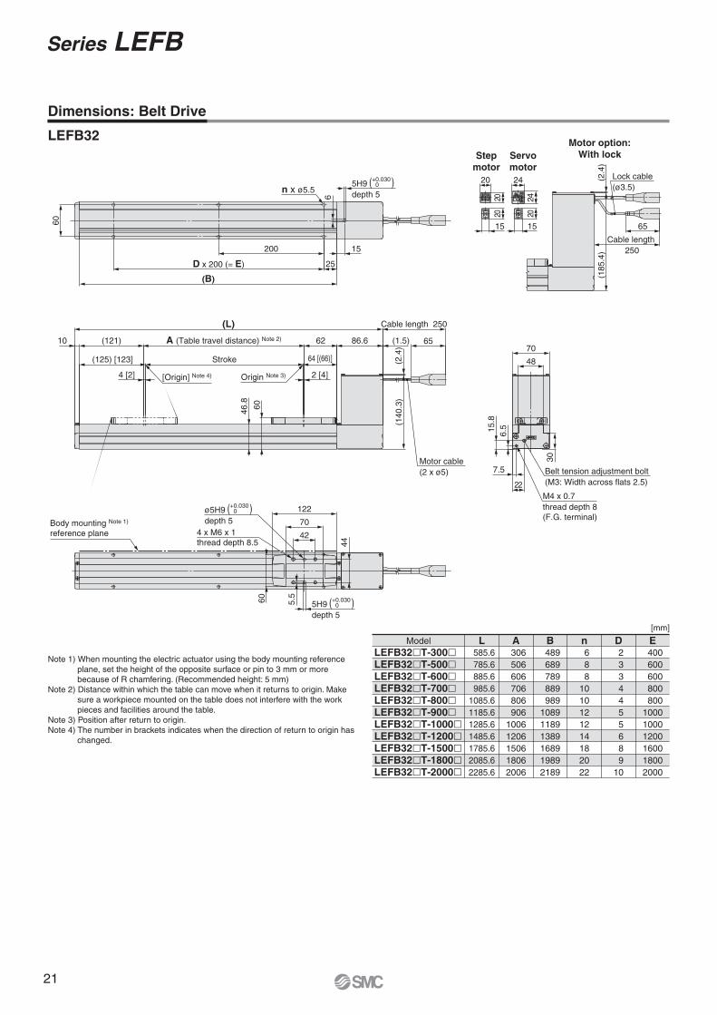
42
70
122
60
44
5H9depth 5
5.5
ø5H9depth 5
60
25
200
D x 200 (= E)
(B)
n x ø5.5
4 x M6 x 1thread depth 8.5
Body mounting Note 1)
reference plane
15
6
( )5H9depth 5
+0.0300
( )+0.0300
( )+0.0300
6046.8
65
Cable length 250
(140
.3)
(2.4
)
30
48
70
65
Cable length 250
(185
.4)
(2.4
)
20
2020
15
Motor cable(2 x ø5) Belt tension adjustment bolt
(M3: Width across flats 2.5)
Lock cable(ø3.5)
Motor option:With lockStep
motorServomotor
20
15
24
24
(L)
22
6.515
.8
7.5
M4 x 0.7thread depth 8(F.G. terminal)
Stroke
2 [4]
64 [(66)]
A (Table travel distance) Note 2) 62
4 [2]
(121) 86.610
(125) [123]
(1.5)
[Origin] Note 4) Origin Note 3)
Note 1) When mounting the electric actuator using the body mounting reference plane, set the height of the opposite surface or pin to 3 mm or more because of R chamfering. (Recommended height: 5 mm)
Note 2) Distance within which the table can move when it returns to origin. Make sure a workpiece mounted on the table does not interfere with the work pieces and facilities around the table.
Note 3) Position after return to origin.Note 4) The number in brackets indicates when the direction of return to origin has
changed.
LEFB32
LEFB32�T-300�LEFB32�T-500�LEFB32�T-600�LEFB32�T-700�LEFB32�T-800�LEFB32�T-900�LEFB32�T-1000�LEFB32�T-1200�LEFB32�T-1500�LEFB32�T-1800�LEFB32�T-2000�
Model L 585.6 785.6 885.6 985.61085.61185.61285.61485.61785.62085.62285.6
A 489 689 789 889 989108911891389168919892189
306 506 606 706 806 90610061206150618062006
B 6 8 81010121214182022
n 2 3 3 4 4 5 5 6 8 910
D 400 600 600 800 800100010001200160018002000
E
Dimensions: Belt Drive
[mm]
Series LEFB
21

Design
Caution1. Do not apply a load in excess of the operating limit.
A product should be selected based on the maximum load and allowable moment. If the product is used outside of the operating limit, eccentric load applied to the guide will become excessive and have adverse effects such as creating play at the guide, degraded accuracy and shortened product life.
2. Do not use the product in applications where exces-sive external force or impact force is applied to it.This can cause failure.
Handling
Caution
Handling
Caution
1. Please set the position determination width in the step data to at least 0.5 (at least 1 for the belt type).If in position is 0.5 or less, completion signal of in position may not be output.
2. INP output signal1) Positioning operation
When the product comes within the set range by step data [In position], the INP output signal will be turned on.Initial value: Set to [0.50] or higher.
3. Never hit at the stroke end other than returning to the original position.The internal stopper can be broken.
Handle the actuator with care especially when it is used in the vertical direction.
4. The positioning force should be the initial value.If the positioning force is set below the initial value, it may cause an alarm.
5. Actual speed of the product can be changed by load.When selecting a product, check the catalogue for the instruc-tions regarding selection and specifications.
6. Do not apply a load, impact or resistance in addi-tion to a transferred load during returning to the original position.Otherwise, the original position can be displaced since it is based on detected motor torque.
7. Do not dent, scratch or cause other damage to the body and table mounting surfaces.It may cause a loss of parallelism in the mounting surfaces, looseness in the guide unit, an increase in sliding resistance or other problems.
8. When attaching a workpiece, do not apply strong impact or large moment.If an external force over the allowable moment is applied, it may cause looseness in the guide unit, an increase in sliding resistance or other problems.
9. Keep the flatness of mounting surface 0.1 mm or less.Insufficient flatness of a workpiece or base mounted on the body of the product can cause play at the guide and increased sliding resistance.
10. When mounting the product, keep the 40 mm or more for bending the cable.
11. Do not hit the table with the workpiece in the posi-tioning operation and positioning range.
Series LEFElectric Actuator/Specific Product Precautions 1Be sure to read before handling. Refer to back cover for Safety Instructions and the Operation Manual for Electric Actuator Precautions.Please download it via our website. http://www.smcworld.com
Ser
vo M
otor
(24
VD
C)/
Ste
p M
otor
(S
ervo
/24
VD
C)
Mod
el S
elec
tion
Spec
ific P
roduc
t Prec
autio
nsA
C S
ervo
Mot
or
22
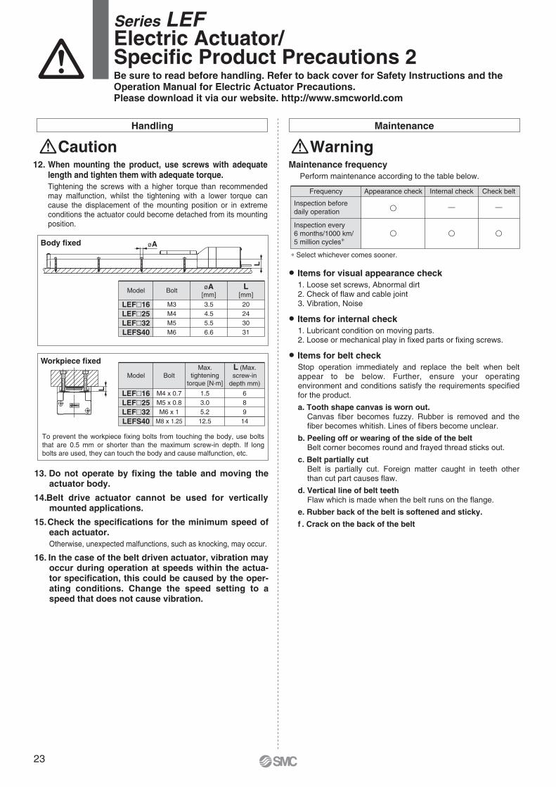
Handling
Caution12. When mounting the product, use screws with adequate
length and tighten them with adequate torque.Tightening the screws with a higher torque than recommended may malfunction, whilst the tightening with a lower torque can cause the displacement of the mounting position or in extreme conditions the actuator could become detached from its mounting position.
LEF�16LEF�25LEF�32LEFS40
Model
M4 x 0.7M5 x 0.8M6 x 1
M8 x 1.25
Bolt
1.53.05.212.5
Max.tightening
torque [N·m]
689
14
L (Max.screw-in
depth mm)
To prevent the workpiece fixing bolts from touching the body, use bolts that are 0.5 mm or shorter than the maximum screw-in depth. If long bolts are used, they can touch the body and cause malfunction, etc.
Workpiece fixed
Body fixed
LEF�16LEF�25LEF�32LEFS40
Model
M3M4M5M6
Bolt
3.54.55.56.6
øA[mm]
20243031
L[mm]
L
L
øA
13. Do not operate by fixing the table and moving the actuator body.
14. Belt drive actuator cannot be used for vertically mounted applications.
15. Check the specifications for the minimum speed of each actuator.Otherwise, unexpected malfunctions, such as knocking, may occur.
16. In the case of the belt driven actuator, vibration may occur during operation at speeds within the actua-tor specification, this could be caused by the oper-ating conditions. Change the speed setting to a speed that does not cause vibration.
Maintenance
WarningMaintenance frequency
Perform maintenance according to the table below.
� Items for visual appearance check1. Loose set screws, Abnormal dirt2. Check of flaw and cable joint3. Vibration, Noise
� Items for internal check1. Lubricant condition on moving parts.2. Loose or mechanical play in fixed parts or fixing screws.
� Items for belt checkStop operation immediately and replace the belt when belt appear to be below. Further, ensure your operating environment and conditions satisfy the requirements specified for the product.
a. Tooth shape canvas is worn out.Canvas fiber becomes fuzzy. Rubber is removed and the fiber becomes whitish. Lines of fibers become unclear.
b. Peeling off or wearing of the side of the beltBelt corner becomes round and frayed thread sticks out.
c. Belt partially cutBelt is partially cut. Foreign matter caught in teeth other than cut part causes flaw.
d. Vertical line of belt teethFlaw which is made when the belt runs on the flange.
e. Rubber back of the belt is softened and sticky.
f . Crack on the back of the belt
Inspection beforedaily operation
Inspection every 6 months/1000 km/5 million cycles∗
�
Appearance check
—
Internal checkFrequency
—
� � �
Check belt
∗ Select whichever comes sooner.
Series LEFElectric Actuator/Specific Product Precautions 2Be sure to read before handling. Refer to back cover for Safety Instructions and the Operation Manual for Electric Actuator Precautions.Please download it via our website. http://www.smcworld.com
23
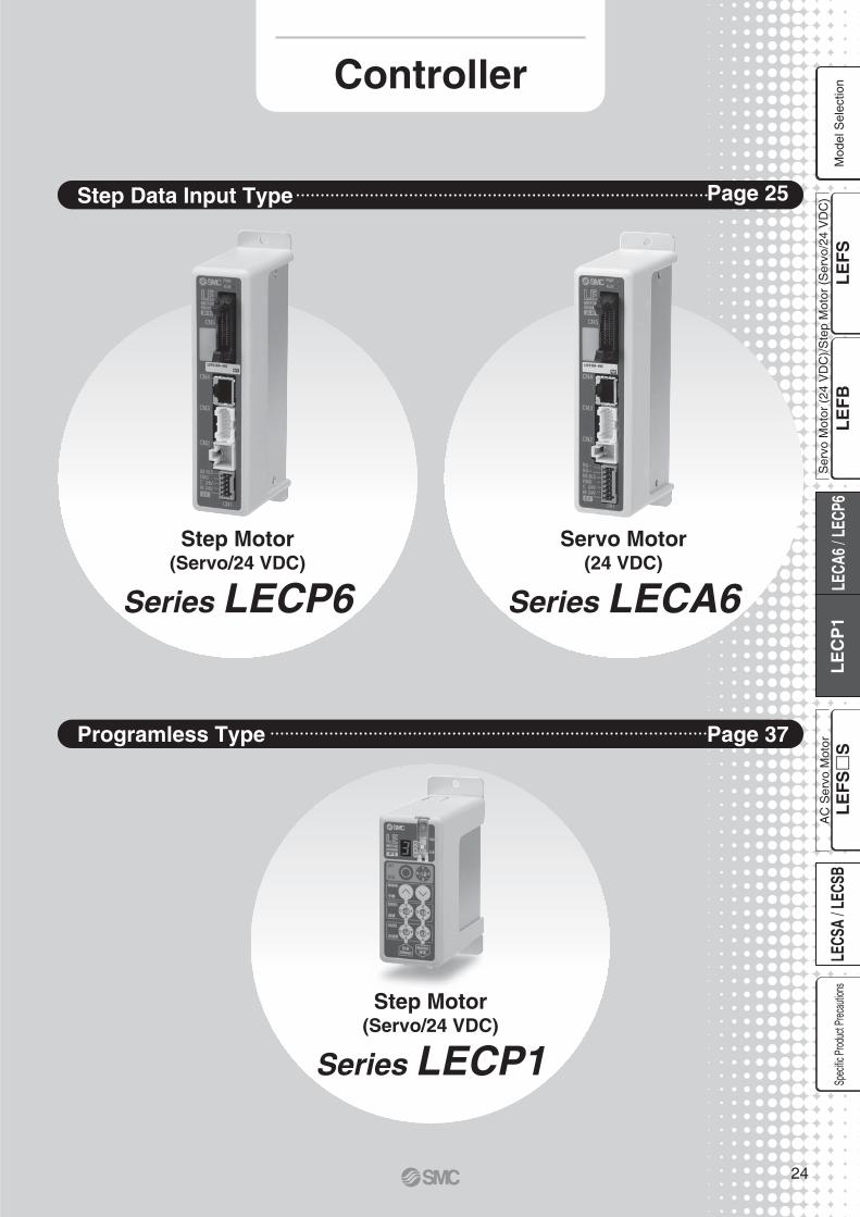
Series LECP6
Series LECP1
Step Motor(Servo/24 VDC)
Step Motor(Servo/24 VDC)
Series LECA6
Servo Motor(24 VDC)
Step Data Input Type Page 25
Programless Type Page 37
Controller
Ser
vo M
otor
(24
VD
C)/
Ste
p M
otor
(S
ervo
/24
VD
C)
Mod
el S
elec
tion
Spec
ific P
roduc
t Prec
autio
nsA
C S
ervo
Mot
or
24
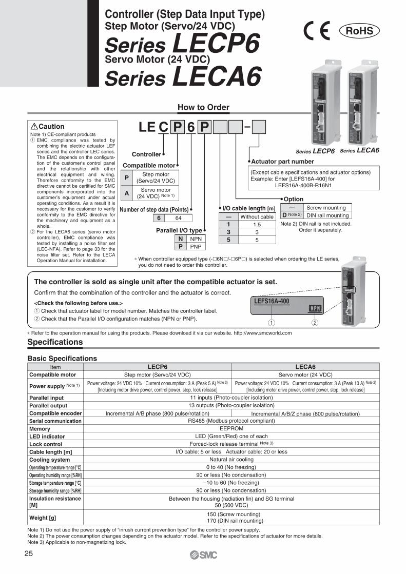
Series LECA6Servo Motor (24 VDC)Series LECP6Step Motor (Servo/24 VDC)Controller (Step Data Input Type)
RoHS
Confirm that the combination of the controller and the actuator is correct.
The controller is sold as single unit after the compatible actuator is set.
<Check the following before use.>q Check that actuator label for model number. Matches the controller label.w Check that the Parallel I/O configuration matches (NPN or PNP).
How to Order
Specifications
Basic SpecificationsItem LECP6 LECA6
Compatible motor
Power supply Note 1)
Parallel inputParallel outputCompatible encoderSerial communicationMemoryLED indicatorLock controlCable length [m]Cooling systemOperating temperature range [°C]Operating humidity range [%RH]Storage temperature range [°C]Storage humidity range [%RH]
Weight [g]
Insulation resistance [M]
Step motor (Servo/24 VDC)
Power voltage: 24 VDC 10% Current consumption: 3 A (Peak 5 A) Note 2)
[Including motor drive power, control power, stop, lock release]
Servo motor (24 VDC)
Power voltage: 24 VDC 10% Current consumption: 3 A (Peak 10 A) Note 2)
[Including motor drive power, control power, stop, lock release]
Between the housing (radiation fin) and SG terminal50 (500 VDC)
Incremental A/B phase (800 pulse/rotation) Incremental A/B/Z phase (800 pulse/rotation)
150 (Screw mounting)170 (DIN rail mounting)
Note 1) Do not use the power supply of “inrush current prevention type” for the controller power supply.Note 2) The power consumption changes depending on the actuator model. Refer to the specifications of actuator for more details.Note 3) Applicable to non-magnetizing lock.
11 inputs (Photo-coupler isolation)13 outputs (Photo-coupler isolation)
RS485 (Modbus protocol compliant)EEPROM
LED (Green/Red) one of eachForced-lock release terminal Note 3)
I/O cable: 5 or less Actuator cable: 20 or lessNatural air cooling
0 to 40 (No freezing)90 or less (No condensation)
–10 to 60 (No freezing)90 or less (No condensation)
(Except cable specifications and actuator options)Example: Enter [LEFS16A-400] for
LEFS16A-400B-R16N1
LE C P 6 P
P
A Servo motor(24 VDC) Note 1)
Step motor(Servo/24 VDC)
6 64
Number of step data (Points)
NP
NPNPNP
Parallel I/O type
—135
Without cable1.535
I/O cable length [m] —D Note 2)
Screw mountingDIN rail mounting
Option
Actuator part numberCompatible motor
Controller
Note 2) DIN rail is not included. Order it separately.
Note 1) CE-compliant productsq EMC compliance was tested by
combining the electric actuator LEF series and the controller LEC series. The EMC depends on the configura-tion of the customer’s control panel and the relationship with other electrical equipment and wiring. Therefore conformity to the EMC directive cannot be certified for SMC components incorporated into the customer’s equipment under actualoperating conditions. As a result it is necessary for the customer to verify conformity to the EMC directive for the machinery and equipment as a whole.
w For the LECA6 series (servo motor controller), EMC compliance was tested by installing a noise filter set (LEC-NFA). Refer to page 33 for the noise filter set. Refer to the LECA Operation Manual for installation.
Caution
∗ When controller equipped type (-�6N�/-�6P�) is selected when ordering the LE series, you do not need to order this controller.
∗ Refer to the operation manual for using the products. Please download it via our website. http://www.smcworld.com
q w
LEFS16A-400
Series LECP6 Series LECA6
25

DIN railAXT100-DR-�
DIN rail mounting adapterLEC-D0 (with 2 mounting screws)
This should be used when the DIN rail mounting adapter is mounted onto the screw mounting type controller afterwards.
∗ For �, enter a number from the “No.” line in the table below.Refer to the dimensions on page 27 for the mounting dimensions.
40
510.5
39
498
38
485.5
37
473
36
460.5
35
448
34
435.5
33
423
32
410.5
31
398
30
385.5
29
373
28
360.5
27
348
26
335.5
25
323
24
310.5
23
298
22
285.5
21
273
No.
L
20
260.5
19
248
18
235.5
17
223
16
210.5
15
198
14
185.5
13
173
12
160.5
11
148
10
135.5
9
123
8
110.5
7
98
6
85.5
5
73
4
60.5
3
48
2
35.5
1
23
No.
L
L Dimension [mm]
7.5
(25)
(35)
A
L
5.5
5.2512.5(Pitch)
1.25
How to Mount
a) Screw mounting (LEC�6��-�)(Installation with two M4 screws)
b) DIN rail mounting (LEC�6��D-�)(Installation with the DIN rail)
Ground wire
DIN rail
DIN rail is locked.
Mounting direction
Mounting direction
Ground wire Groundwire
Hook the controller on the DIN rail and press the lever of section A in the arrow direction to lock it.
DIN rail mounting adapter
Controller (Step Data Input Type)/Step Motor (Servo/24 VDC) Series LECP6Controller (Step Data Input Type)/Servo Motor (24 VDC) Series LECA6
Ser
vo M
otor
(24
VD
C)/
Ste
p M
otor
(S
ervo
/24
VD
C)
Mod
el S
elec
tion
Spec
ific P
roduc
t Prec
autio
nsA
C S
ervo
Mot
or
26

31
150
132
4.6for bodymounting
35
141
ø4.5for bodymountingPower supply LED (Green)
(ON: Power supply is ON.)
CN5 parallel I/O connector
CN4 serial I/O connector
CN3 encoder connector
CN2 motor power connector
CN1 power supply connector
Power supply LED (Red)(ON: Alarm is ON.)
31
35
132
150
167.
3 (W
hen
lock
ing
DIN
rai
l)
173.
2 (W
hen
rem
ovin
g D
IN r
ail)
Refer to page 26 for L dimension andpart number of DIN rail.
166
(81.7)
64.2
35
1
66
(81.7)
(91.7)
(11.5)
b) DIN rail mounting (LEC�6��D-�)
Dimensions
a) Screw mounting (LEC�6��-�)
Series LECP6Series LECA6
27

0VM
24V
C24
VE
MG
BK
RLS
RG
+R
G–
0VM
24V
C24
VE
MG
BK
RLS
Wiring Example 1
CN1 Power Supply Connector Terminal for LECP6 (PHOENIX CONTACT FK-MC0.5/5-ST-2.5)Terminal name Function Function details
0V
M24VC24VEMG
BK RLS
Common supply (–)
Motor power supply (+)Control power supply (+)
Stop (+)Lock release (+)
This is the motor power supply (+) that is supplied to the controller.This is the control power supply (+) that is supplied to the controller.This is the input (+) that releases the stop.This is the input (+) that releases the lock.
M24V terminal/C24V terminal/EMG terminal/BK RLS terminal are common (–).
CN1 Power Supply Connector Terminal for LECA6 (PHOENIX CONTACT FK-MC0.5/7-ST-2.5)Terminal name Function Function details
0V
M24VC24VEMG
BK RLSRG+RG–
Common supply (–)
Motor power supply (+)Control power supply (+)
Stop (+)Lock release (+)
Regenerative output 1Regenerative output 2
This is the motor power supply (+) that is supplied to the controller.This is the control power supply (+) that is supplied to the controller.This is the input (+) that releases the stop.This is the input (+) that releases the lock.These are the regenerative output terminals for external connection. (It is not necessary to connect them in the combination with standard specification LE series.)
M24V terminal/C24V terminal/EMG terminal/BK RLS terminal are common (–).
Power Supply Connector: CN1 ∗ Power supply plug is an accessory. Power supply plug for LECP6
Power supply plug for LECA6
COM+
COM–
IN0
IN1
IN2
IN3
IN4
IN5
SETUP
HOLD
DRIVE
RESET
SVON
OUT0
OUT1
OUT2
OUT3
OUT4
OUT5
BUSY
AREA
SETON
INP
SVRE
∗ESTOP
∗ALARM
CN5A1
A2
A3
A4
A5
A6
A7
A8
A9
A10
A11
A12
A13
B1
B2
B3
B4
B5
B6
B7
B8
B9
B10
B11
B12
B13
24 VDCfor I/O signal
24 VDCfor I/O signal
Load
COM+
COM–
IN0
IN1
IN2
IN3
IN4
IN5
SETUP
HOLD
DRIVE
RESET
SVON
OUT0
OUT1
OUT2
OUT3
OUT4
OUT5
BUSY
AREA
SETON
INP
SVRE
∗ESTOP
∗ALARM
A1
A2
A3
A4
A5
A6
A7
A8
A9
A10
A11
A12
A13
B1
B2
B3
B4
B5
B6
B7
B8
B9
B10
B11
B12
B13
CN5
Load
Wiring Example 2
Wiring diagramLEC�6N��-� (NPN) LEC�6P��-� (PNP)
Input SignalName ContentsCOM +COM –
IN0 to IN5
SETUPHOLDDRIVERESETSVON
Connects the power supply 24 V for input/output signalConnects the power supply 0 V for input/output signal
Instruction to return to the original positionOperation is temporarily stopped
Instruction to driveAlarm reset and operation interruption
Servo ON instruction
Step data specified Bit No.(Input is instructed in the combination of IN0 to 5.)
Output SignalName Contents
OUT0 to OUT5BUSYAREA
SETON
INP
SVRE∗ESTOP Note)
∗ALARM Note)
Outputs the step data No. during operationOutputs when the actuator is moving
Outputs within the step data area output setting rangeOutputs when returning to the original position
Outputs when servo is onNot output when EMG stop is instructed
Not output when alarm is generated
Outputs when target position or target force is reached(Turns on when the positioning or pushing is completed.)
Note) These signals are output when the power supply of the controller is ON. (N.C.)
Parallel I/O Connector: CN5 ∗ When you connect a PLC, etc., to the CN5 parallel I/O connector, please use the I/O cable (LEC-CN5-�).∗ The wiring should be changed depending on the type of the parallel I/O (NPN or PNP). Please wire referring
to the following diagram.
Controller (Step Data Input Type)/Step Motor (Servo/24 VDC) Series LECP6Controller (Step Data Input Type)/Servo Motor (24 VDC) Series LECA6
Ser
vo M
otor
(24
VD
C)/
Ste
p M
otor
(S
ervo
/24
VD
C)
Mod
el S
elec
tion
Spec
ific P
roduc
t Prec
autio
nsA
C S
ervo
Mot
or
28
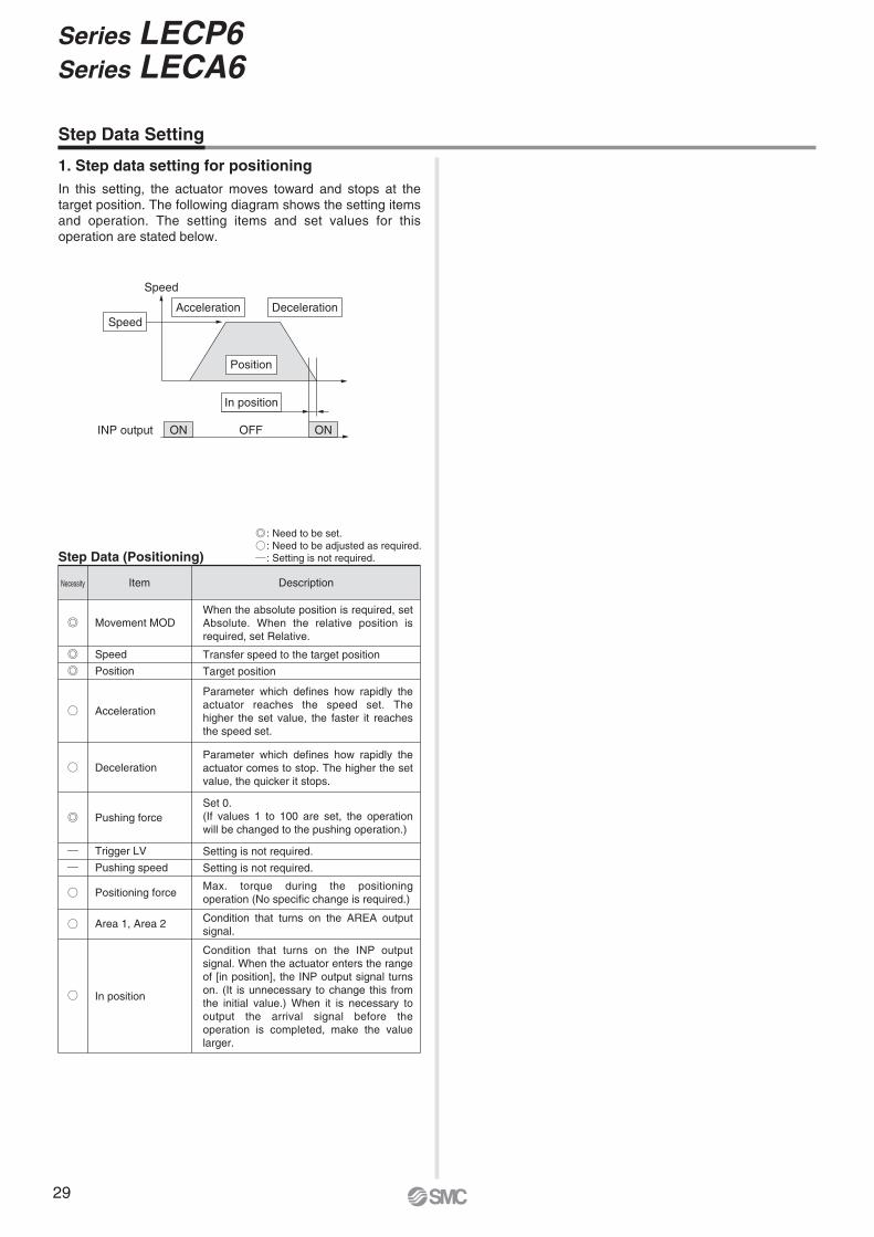
Speed
Speed
INP output OFF
In position
Acceleration Deceleration
ONON
Position
Step Data (Positioning)
: Need to be set.: Need to be adjusted as required.: Setting is not required.
ItemNecessity Description
Movement MOD
In position
Area 1, Area 2
Positioning force
Trigger LV
Pushing speed
Pushing force
Deceleration
Acceleration
Speed
Position
When the absolute position is required, set Absolute. When the relative position is required, set Relative.
Set 0.(If values 1 to 100 are set, the operation will be changed to the pushing operation.)
Max. torque during the positioning operation (No specific change is required.)
Transfer speed to the target position
Setting is not required.
Condition that turns on the AREA output signal.
Setting is not required.
Target position
Parameter which defines how rapidly the actuator reaches the speed set. The higher the set value, the faster it reaches the speed set.
Parameter which defines how rapidly the actuator comes to stop. The higher the set value, the quicker it stops.
Condition that turns on the INP output signal. When the actuator enters the range of [in position], the INP output signal turns on. (It is unnecessary to change this from the initial value.) When it is necessary to output the arrival signal before the operation is completed, make the value larger.
Step Data Setting
1. Step data setting for positioningIn this setting, the actuator moves toward and stops at the target position. The following diagram shows the setting items and operation. The setting items and set values for this operation are stated below.
Series LECP6Series LECA6
29

Power supply
SVON
SETUP
BUSY
SVRE
SETON
INP
∗ALARM
∗ESTOP
Input
Output
Speed
Return to origin
24 V 0 V
ONOFF
0 mm/s
ONOFF
If the actuator is within the “in position” range of the basic parameter, INP will be turned ON, but if not, it will remain OFF.
∗ “∗ALARM” and “∗ESTOP” are expressed as negative-logic circuit.
∗ When the actuator is in the positioning range in the pushing operation, it does not stop even if HOLD signal is input. ∗ “∗ALARM” is expressed as negative-logic circuit.
∗ “OUT” is output when “DRIVE” is changed from ON to OFF.(When power supply is applied, “DRIVE” or “RESET” is turned ON or “∗ESTOP” is turned OFF, all of the “OUT” outputs are turned OFF.)
HOLD
BUSY
Input
Output
SpeedHOLD during the operation
ONOFF
0 mm/s
ONOFF
RESET
OUT
∗ALARM
Input
Output
ONOFF
ONOFF
ONOFF
Alarm out
Alarm reset
It is possible to identify the alarm group by the combination of OUT signals when the alarm is generated.
Slow-down starting point
Signal Timing
Return to Origin
HOLD Reset
Controller (Step Data Input Type)/Step Motor (Servo/24 VDC) Series LECP6Controller (Step Data Input Type)/Servo Motor (24 VDC) Series LECA6
IN
DRIVE
OUT
BUSY
INP
Input
Output
SpeedPositioning operation
ONOFF
0 mm/s
ONOFF
Scan the stepdata no.
Output the step data no.
If the actuator is within the “in position” range of the step data, INP will be turned ON, but if not, it will remain OFF.
Positioning Operation
15 msor more
Ser
vo M
otor
(24
VD
C)/
Ste
p M
otor
(S
ervo
/24
VD
C)
Mod
el S
elec
tion
Spec
ific P
roduc
t Prec
autio
nsA
C S
ervo
Mot
or
30

(17.
7)(1
7.7)
(30.7)Connector A
L (11)
(30.7) L (11)
(14.2)
(Terminal no.)
(14)
(18)
(14.2)
(14)
(18)
A1 B1
A6 B6
1 25 6
1 2
15 16
(ø8) (Terminal no.)
Connector C
Connector A
(ø5.
5)(ø
6.3)
(Terminal no.) 1 25 6
1 2
15 16
A1 B1
A6 B6
(Terminal no.)
Actuator side
Actuator side
Controller side
(13.5)
(10)Connector D
Connector C
Connector D(14.7)
(13.5)
(10)
(14.7)
Connector Aterminal no.
B-1A-1B-2A-2B-3A-3
AABB
COM-A/COMCOM-B/–
B-4A-4B-5A-5B-6A-6
VccGND
AABB
Circuit Cable colour
BrownRed
OrangeYellowGreenBlue
BrownBlackRed
BlackOrangeBlack
—
Connector Cterminal no.
Cable colour Connector Dterminal no.
216534
121376983
LE-CP- /Cable length: 1.5 m, 3 m, 5 m135
LE-CP- /Cable length: 8 m, 10 m, 15 m, 20 m(∗ Produced upon receipt of order)
8A
BC
Shield
Options: Actuator Cable
[Robotic cable for step motor (Servo/24 VDC), standard cable]
LE CP 1
Cable length (L)[m]1358ABC
1.5358∗
10∗
15∗
20∗
∗ Produced upon receipt of order (Robotic cable only)
Cable type
[Robotic cable with lock and sensor for step motor (Servo/24 VDC), standard cable]
LE CP 1 B
Cable length (L)[m]
With lock and sensor
1358ABC
1.5358∗
10∗
15∗
20∗
∗ Produced upon receipt of order (Robotic cable only)
—Robotic cable (Flexible cable)
Standard cable
Cable type
—
S
Robotic cable (Flexible cable)
Standard cable
B1(Terminal no.)
B6
A1
A6B1B3
A1A3
B1(Terminal no.)
B6
A1
A6
B1B3
A1A3
(ø8)
(ø5.
7)
(17.
7)(1
0.2)
(30.7) L (11)
(14.2)
(14)
(18)
(ø5.
5)
(ø6.
3)(ø
5.7)
(17.
7)(1
0.2)
(30.7) L (11)
(14.2)
(14)
(18)
Actuator side Controller side
Controller side
Actuator sideController side
(Terminal no.)
(Terminal no.)
Connector A
Connector B
Connector A
Connector B
Connector C
Connector D
Connector C
Connector D
(14.7)
(14.7)
1 25 6
1 2
15 16
(13.5)
(10)
1 25 6
1 2
15 16
(13.5)
(10)
LE-CP- /Cable length: 1.5 m, 3 m, 5 m135
LE-CP- /Cable length: 8 m, 10 m, 15 m, 20 m (∗ Produced upon receipt of order)
8A
BC
Connector Aterminal no.
B-1A-1B-2A-2B-3A-3
AABB
COM-A/COMCOM-B/–
B-1A-1B-3A-3
Lock (+)Lock (–)
Sensor (+) Note)
Sensor (–) Note)
B-4A-4B-5A-5B-6A-6
VccGND
AABB
Circuit
Connector Bterminal no.Circuit
Cable colour
BrownRed
OrangeYellowGreenBlue
BrownBlackRed
BlackOrangeBlack
—
Connector Cterminal no.
Cable colour Connector Dterminal no.
216534
121376983
RedBlackBrownBlue
4512
Shield
Note) This is not used for the LEF series.
S
Series LECP6Series LECA6
31
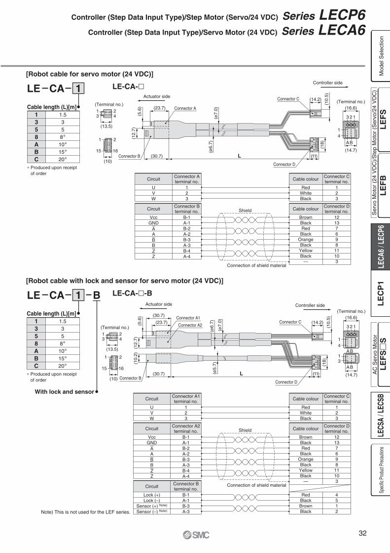
Controller side
Actuator side(Terminal no.)
(Terminal no.)(16.6)(23.7)
(30.7) (11)L
3
1
2 1
(14.7)
4
A
(12.
7)(5
.6)
Connector B
Connector A
(ø7.
0)(ø
6.7)
Connector C (14.2)
(10.
5)(1
8)
Connector D
13
24
1 2
15 16
(13.5)
(10)
Controller sideActuator side
(Terminal no.)
(Terminal no.)
(16.6)(23.7)
(30.7)
(30.7) (11)L
3
1
2 1
4
13
(12.
7)(1
0.2)
(5.6
)
Connector B
Connector A1
(ø7.
0)
(ø6.
7)(ø
5.7)
Connector C (14.2)(1
0.5)
(18)
Connector D
13
24
1 2
15 16
(13.5)
(10)
B
AB
AB
(14.7)
Connector A2
[Robot cable for servo motor (24 VDC)]
[Robot cable with lock and sensor for servo motor (24 VDC)]
LE CA 1
LE CA 1 B
LE-CA-�
LE-CA-�-B
Connector Aterminal no.
123
UVW
Circuit Cable colour
RedWhiteBlack
Connector Cterminal no.
123
Connector Bterminal no.
B-1A-1B-2A-2B-3A-3B-4A-4
VccGND
AABBZZ
Circuit Cable colour
BrownBlackRed
BlackOrangeBlackYellowBlack
—
Connector Dterminal no.
12137698
11103
Shield
Connector A1terminal no.
123
UVW
Circuit
Connector Bterminal no.
B-1A-1B-3A-3
Lock (+)Lock (–)
Sensor (+) Note)
Sensor (–) Note)
Circuit
Cable colour
RedWhiteBlack
Connector Cterminal no.
123
Connector A2terminal no.
B-1A-1B-2A-2B-3A-3B-4A-4
VccGND
AABBZZ
Circuit Cable colour
BrownBlackRed
BlackOrangeBlackYellowBlack
—
Connector Dterminal no.
12137698
11103
RedBlackBrownBlack
4512
Shield
Connection of shield material
Connection of shield material
∗ Produced upon receipt of order
∗ Produced upon receipt of order
With lock and sensor
Note) This is not used for the LEF series.
Controller (Step Data Input Type)/Step Motor (Servo/24 VDC) Series LECP6Controller (Step Data Input Type)/Servo Motor (24 VDC) Series LECA6
Ser
vo M
otor
(24
VD
C)/
Ste
p M
otor
(S
ervo
/24
VD
C)
Mod
el S
elec
tion
Spec
ific P
roduc
t Prec
autio
nsA
C S
ervo
Mot
or
Cable length (L)[m]1358ABC
1.5358∗
10∗
15∗
20∗
Cable length (L)[m]1358ABC
1.5358∗
10∗
15∗
20∗
32

(22.
4)
(14.4) L
B1 A1
B13 A13
A1
B13
A13B1
Controller side PLC side
(ø8.
9) (Terminal no.)
(42.2)(28.8)
(33.
5)
(12.
5)
Option: I/O Cable
Option: Noise Filter Set for Servo Motor (24 VDC)
LEC CN5 1
LEC NFA
Cable length (L) [m]135
1.535
∗ Conductor size: AWG28
∗ Refer to the LECA6 series Operation Manual for installation.
Contents of the set: 2 noise filters (Produced by WURTH ELEKTRONIK: 74271222)
A1Light brownLight brown
YellowYellow
Light greenLight green
GreyGreyWhiteWhite
Light brownLight brown
Yellow
BlackRed
BlackRed
BlackRed
BlackRed
BlackRed
BlackRed
Black
Dotcolour
Dotmark
Insulationcolour
Connectorpin No.
A2A3A4A5A6A7A8A9A10A11A12A13
—
YellowLight greenLight green
GreyGreyWhiteWhite
Light brownLight brown
YellowYellow
Light greenLight green
RedBlackRed
BlackRed
BlackRed
BlackRed
BlackRed
BlackRed
Shield
Dotcolour
Dotmark
Insulationcolour
Connectorpin No.
B1B2B3B4B5B6B7B8B9B10B11B12B13
Series LECP6Series LECA6
33

PC
q Controller setting software
Screen Example
∗ Windows® and Windows XP® are registered trademarks of Microsoft Corporation.
Hardware Requirements
PC/AT compatible machine installed with Windows XP and equipped with USB1.1 or USB2.0 ports.
Easy mode screen example Normal mode screen example
Easy operation and simple setting� Allowing to set and display actuator step
data such as position, speed, force, etc.� Setting of step data and testing of the drive
can be performed on the same page.� Can be used to jog and move at a constant
rate.
Detail setting� Step data can be set in detail.� Signals and terminal status can be monitored.� Parameters can be set.� JOG and constant rate movement, return to origin, test operation and
testing of compulsory output can be performed.
e Conversion unit
w Communication cable
r USB cable (A-mini B type)
HRS
W2LEC
Series LECController Setting Kit/LEC-W2
How to Order
Controller setting kit(Japanese and English are available.)
Contents
q Controller setting software (CD-ROM)
w Communication cable(Cable between the controller and the conversion unit)
e Conversion unit
r USB cable(Cable between the PC and the conversion unit)
Ser
vo M
otor
(24
VD
C)/
Ste
p M
otor
(S
ervo
/24
VD
C)
Mod
el S
elec
tion
Spec
ific P
roduc
t Prec
autio
nsA
C S
ervo
Mot
or
34

Enable switch(Option)
Stop switch
Series LECTeaching Box/LEC-T1
Specifications
Item
Switch
Cable length [m]
Enclosure
Operating temperature range [°C]
Operating humidity range [%RH]
Weight [g]
Stop switch, Enable switch (Option)
3
IP64 (Except connector)
5 to 50
90 or less (No condensation)
350 (Except cable)
DescriptionStandard functions
Option
LEC T1 3 E GEnable switch
SNoneEquipped with enable switch
—Teaching box
Cable length [m]3 3
Stop switchG Equipped with stop switch
∗ Interlock switch for jog test function
Initial languageJE
JapaneseEnglish
How to Order
Note) CE-complianceThe EMC compliance of the teaching box was tested with the LECP6 series step motor controller (servo/24 VDC) and an applicable actuator.
Easy Mode
Function
Step data
Jog
Test
Monitor
Alarm
TB setting
Description
from Position, Speed, Force.
MenuDataMonitorJogTestAlarmTB setting
Jog
Jog operation
Test
Alarm
Alarm reset
TB setting
Set item
DataStep data No.Setting of two items selected below(Position, Speed, Force, Acceleration, Deceleration)
Monitor
(Position, Speed, Force)
Menu Operations Flowchart
RoHS
35

Normal Mode
Function
Step data
Parameter
Test
Monitor
Alarm
File
TB setting
Reconnect
Description
movement
(Specify a maximum of 5 step data and operate.)
(Alarm reset)
Save the step data and parameters of the controller which is being used for communication (it is possible to
step data and parameters defined as one file).
the teaching box to the controller which is being used for communication.
MenuStep dataParameterMonitorTestAlarmFileTB settingReconnect
Step data
SpeedPositionAccelerationDecelerationPushing force
Pushing speedPositioning force
ParameterBasic
DRV monitor
Active ALMActive alarm displayAlarm reset
ALM Log record display
MonitorDrive
Test
Test drive
Alarm
TB setting
BeepMax. connection axisPasswordDistance unit
Reconnect
Basic setting
ORIG setting
Output signal monitor
Input signal monitor
Output terminal monitor
Input terminal monitor
FileData saving
File deletion
Menu Operations Flowchart
185
4 34.5w
q
r
t
y e
iu
Dimensions
1
2
3
4
5
6
7
8
LCD
Ring
Stop switch
Stop switch guard
Enable switch(Option)
Key switch
Cable
Connector
A ring for hanging the teaching box
A guard for the stop switch
Switch for each input
FunctionDescription
Prevents unintentional operation (unexpected
such as data change are not covered.
Mod
el S
elec
tion
Spec
ific P
roduc
t Prec
autio
ns
Teaching Box Series LEC
36
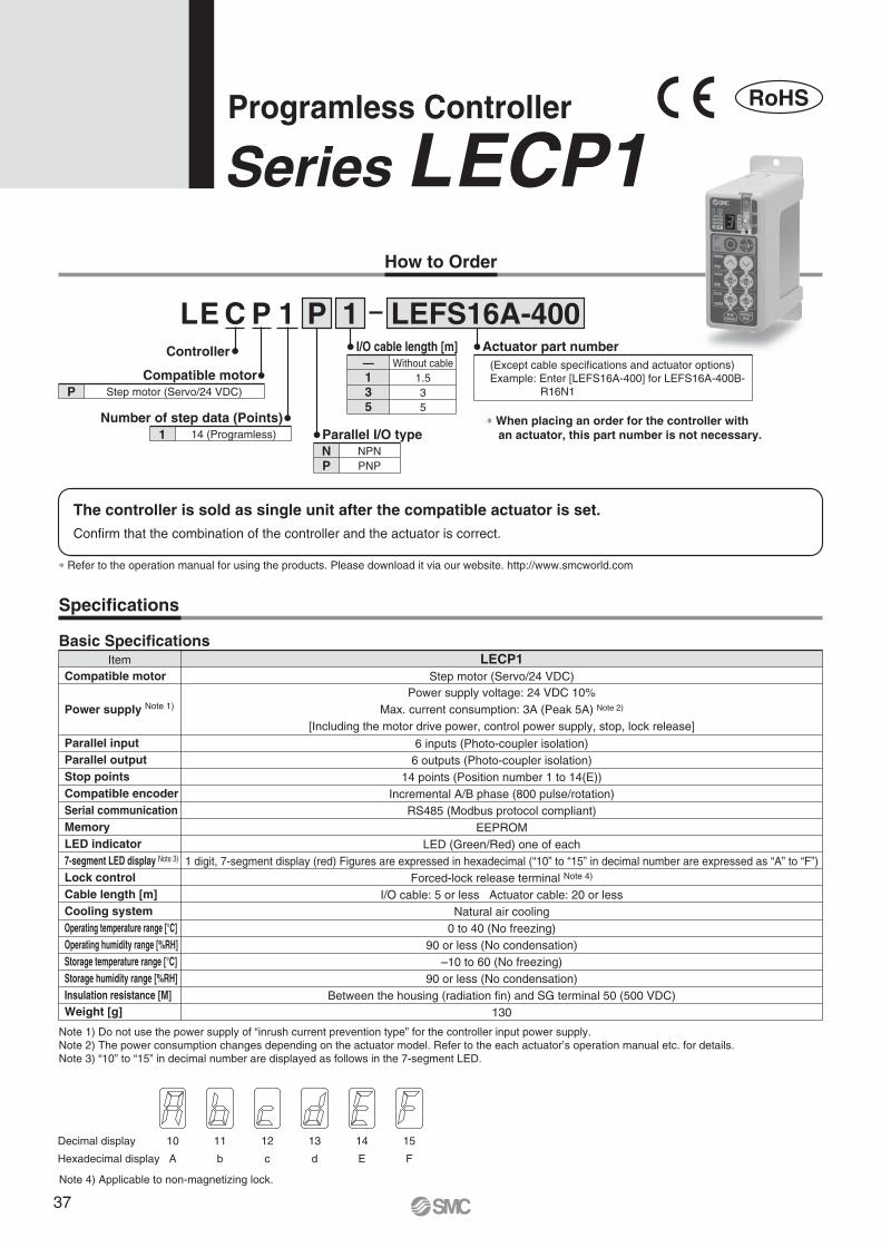
C 1LE P 1PController
Compatible motorP Step motor (Servo/24 VDC)
Number of step data (Points)1 14 (Programless) Parallel I/O type
NP
NPNPNP
I/O cable length [m]—135
Without cable1.535
Actuator part number(Except cable specifications and actuator options)Example: Enter [LEFS16A-400] for LEFS16A-400B-
R16N1
∗ When placing an order for the controller with an actuator, this part number is not necessary.
LEFS16A-400
How to Order
Programless Controller
Series LECP1
Confirm that the combination of the controller and the actuator is correct.
The controller is sold as single unit after the compatible actuator is set.
Specifications
Basic SpecificationsItem LECP1
Compatible motor
Power supply Note 1)
Parallel inputParallel outputStop pointsCompatible encoderSerial communicationMemoryLED indicator7-segment LED display Note 3)
Lock controlCable length [m]Cooling systemOperating temperature range [°C]Operating humidity range [%RH]Storage temperature range [°C]Storage humidity range [%RH]Insulation resistance [M]Weight [g]
Step motor (Servo/24 VDC)Power supply voltage: 24 VDC 10%
Max. current consumption: 3A (Peak 5A) Note 2)
[Including the motor drive power, control power supply, stop, lock release]
6 inputs (Photo-coupler isolation)6 outputs (Photo-coupler isolation)
14 points (Position number 1 to 14(E))Incremental A/B phase (800 pulse/rotation)
RS485 (Modbus protocol compliant)EEPROM
LED (Green/Red) one of each1 digit, 7-segment display (red) Figures are expressed in hexadecimal (“10” to “15” in decimal number are expressed as “A” to “F”)
Forced-lock release terminal Note 4)
I/O cable: 5 or less Actuator cable: 20 or lessNatural air cooling
0 to 40 (No freezing)90 or less (No condensation)
–10 to 60 (No freezing)90 or less (No condensation)
Between the housing (radiation fin) and SG terminal 50 (500 VDC)130
Note 1) Do not use the power supply of “inrush current prevention type” for the controller input power supply.Note 2) The power consumption changes depending on the actuator model. Refer to the each actuator’s operation manual etc. for details.Note 3) “10” to “15” in decimal number are displayed as follows in the 7-segment LED.
Note 4) Applicable to non-magnetizing lock.
Decimal display
Hexadecimal display
10
A
11
b
12
c
13
d
14
E
15
F
RoHS
∗ Refer to the operation manual for using the products. Please download it via our website. http://www.smcworld.com
37

Display
PWR
ALM
—
—
—
—
SET—
MANUAL
SPEED
ACCEL
CN1CN2
CN3CN4
Description
Power supply LED
Alarm LED
Cover
FG
Mode swith
7-segment LED
Set button
Position selecting switch
Manual forward button
Manual reverse button
Forward speed switch
Reverse speed switch
Forward acceleration switch
Reverse acceleration switch
Power supply connector
Motor connector
Encoder connector
I/O connector
Details
Power supply ON/servo ON :Green turns on
Power supply ON/servo OFF :Green flashes
With alarm : Red turns on
Parameter setting : Red flashes
Switch the mode between manual and auto.
Stop position, the value set by � and alarm information are displayed.
Decide the settings or drive operation in Manual mode.
Assign the position to drive (1 to 14), and the origin position (15).
Perform forward jog and inching.
Perform reverse jog and inching.
16 forward speeds are available.
16 reverse speeds are available.
16 forward acceleration steps are available.
16 reverse acceleration steps are available.
Connect the power supply cable.
Connect the motor connector.
Connect the encoder connector.
Connect I/O cable.
No.
q
w
e
r
t
y
u
i
o
!0
!1
!2
!3
!4
!5
!6
!7
!8
er
t
y
u i
o !0
!1 !2
!3 !4
!5
!6
!7
!8
Details of The Controller
CautionM4 screws, cable with crimping terminal and tooth lock washer are not included.
Be sure to carry out grounding earth in order to ensure the noise tolerance.
Use a watchmaker's screwdriver of the size shown below when changing
position switch i and the set value of the speed/acceleration switch !1 to !4.SizeEnd width L :2.0 to 2.4 [mm]End thickness W :0.5 to 0.6 [mm]
How to Mount
Controller mounting shown below.
1. Mounting screw (LECP1��-�)(Installation with two M4 screws)
2. GroundingTighten the bolt with the nut when mounting the ground wire as shown below.
L
W
Magnified view of the end of the screwdriver
Mounting direction
Mounting direction
Ground wire
Change and protection of the mode SW (Close the cover after changing SW)
Frame ground (Tighten the bolt with the nut when mounting the controller. Connect the ground wire.)
M4 screw
Cable with crimping terminal
Tooth lock washer
Controller
q
w
Programless Controller Series LECP1
Ser
vo M
otor
(24
VD
C)/
Ste
p M
otor
(S
ervo
/24
VD
C)
Mod
el S
elec
tion
Spec
ific P
roduc
t Prec
autio
nsA
C S
ervo
Mot
or
38

85
1.2
CN4 I/O connector
CN1 power supply connector
CN3 encoder connector
CN2 motor connector
ø4.5for body mounting
101
110
8638
4.5for body mounting
36.2
18.1
4.5
Dimensions
Series LECP1
39

COM+
COM–
IN0
IN1
IN2
IN3
RESET
STOP
OUT0
OUT1
OUT2
OUT3
BUSY
ALARM
CN41
2
9
10
11
12
13
14
3
4
5
6
7
8
Power supply 24 VDCfor I/O signal
Load
COM+
COM–
IN0
IN1
IN2
IN3
RESET
STOP
OUT0
OUT1
OUT2
OUT3
BUSY
ALARM
1
2
9
10
11
12
13
14
3
4
5
6
7
8
CN4Power supply 24 VDC
for I/O signal
Load
Wiring Example 1
Power Supply Connector: CN1
NPN PNP
Wiring Example 2
Parallel I/O Connector: CN4 ∗ When you connect a PLC, etc., to the CN4 parallel I/O connector, please use the I/O cable (LEC-CK4-�).∗ The wiring should be changed depending on the type of the parallel I/O (NPN or PNP). Please wire referring
to the following diagram.
∗ When you connect a CN1 power supply connector, please use the power supply cable (LEC-CK1-1).∗ Power supply cable (LEC-CK1-1) is an accessory.
M24V terminal/C24V terminal/BK RLS terminal are common (–).
This is the motor power supply (+) that is supplied to the controller.
This is the control power supply (+) that is supplied to the controller.
Terminal name Cable colour Function Function details
0V
M24V
C24V
BK RLS
Blue
White
Brown
Black
Commonsupply (–)
Motor powersupply (+)
Control powersupply (+)
Lock release (+) This is the input (+) that releases the lock.
Name
COM+
COM–
IN0 to IN3
RESET
STOP
Connects the power supply 24 V for input/output signal
Connects the power supply 0 V for input/output signal
� Instruction to drive (input as a combination of IN0 to IN3) � Instruction to return to the origin position (IN0 to IN3 all ON simultaneously) Example - (instruction to drive for position no. 5)
Alarm reset and operation interruption
During operation : deceleration stop from position at which
signal is input (servo ON maintained)
While alarm is active : alarm reset
Instruction to stop (after maximum deceleration stop, servo OFF)
Contents
IN0ON
IN1OFF
IN3OFF
IN2ON
Name
OUT0 to OUT3
BUSY∗ALARM Note)
Turns on when the positioning or pushing is completed.
(Output is instructed in the combination of OUT0 to 3.) Example - (operation complete for position no. 3)
Outputs when the actuator is moving
Not output when alarm is active or servo OFF
Note) These signals are output when the power supply of the controller is ON. (N.C.)
Contents
OUT0ON
OUT1ON
OUT3OFF
OUT2OFF
Input Signal
Position number123456789
10 (A)11 (B)12 (C)13 (D)14 (E)
Retun to origin
IN3 IN2 IN1 IN0Input Signal [IN0 - IN3] Position Number Chart �: OFF �: ON
Position number123456789
10 (A)11 (B)12 (C)13 (D)14 (E)
Retun to origin
OUT3 OUT2 OUT1 OUT0Output Signal [OUT0 - OUT3] Position Number Chart �: OFF �: ON
Output Signal
CN1 Power Supply Connector Terminal for LECP1 Power supply cable for LECP1 (LEC-CK1-1)
Programless Controller Series LECP1
Ser
vo M
otor
(24
VD
C)/
Ste
p M
otor
(S
ervo
/24
VD
C)
Mod
el S
elec
tion
Spec
ific P
roduc
t Prec
autio
nsA
C S
ervo
Mot
or
40

Power supply
IN0-3
BUSY
OUT0-3
∗ ALARM
Input
Output
External Lock
Speed
Return to origin
24 V 0 V
24 V 0 V
ReleaseHold
ONOFF
0 mm/s
ONOFF
ReleaseHold
IN0-3
OUT0-3
BUSY
Input
Power supply
Output
External Lock
SpeedPositioning operation
ONOFF
0 mm/s
ONOFF
Output signal for OUT0, OUT1, OUT2, OUT3 are ON when return to origin is completed.
After ON controller system initialization
∗ “∗ALARM” is expressed as negative-logic circuit.
∗ “∗ALARM” is expressed as negative-logic circuit.
OUT0-3 output signal are ON in the same state as the input IN0-3 when positioning is completed.
24 V 0 V
ReleaseHold
IN0-3
RESET
OUT0-3
BUSY
Input
Power supply
Output
External Lock
SpeedCut-off stop during
positioning operation.
ONOFF
0 mm/s
ONOFF
24 V 0 V
ReleaseHold
IN0-3
STOP
OUT0-3
BUSY
∗ ALARM
Input
Power supply
Output
External Lock
SpeedStop by the STOP signal during
positioning operation.
ONOFF
0 mm/s
ONOFF
RESET
∗ ALARM
Input
Output
ONOFF
ONOFF
Alarm out
Alarm reset
IN0-3 all ON
(2) Positioning Operation
(3) Cut-off Stop (Reset Stop)
(4) Stop by The STOP Signal
(5) Alarm Reset
Signal Timing
(1) Return to Origin
Series LECP1
41
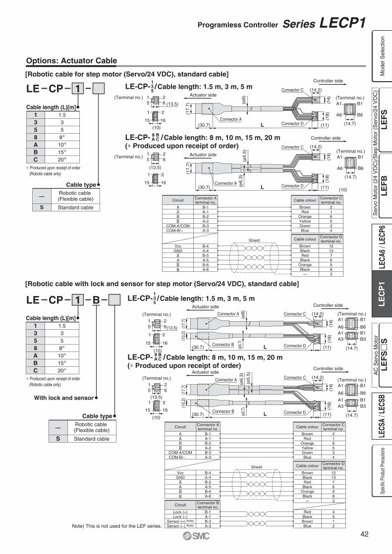
(17.
7)(1
7.7)
(30.7)Connector A
L (11)
(30.7) L (11)
(14.2)
(Terminal no.)
(14)
(18)
(14.2)
(14)
(18)
A1 B1
A6 B6
1 25 6
1 2
15 16
(ø8) (Terminal no.)
Connector C
Connector A
(ø5.
5)(ø
6.3)
(Terminal no.) 1 25 6
1 2
15 16
A1 B1
A6 B6
(Terminal no.)
Actuator side
Actuator side
Controller side
(13.5)
(10)Connector D
Connector C
Connector D
(14.7)
(13.5)
(10)
(14.7)
Connector Aterminal no.
B-1A-1B-2A-2B-3A-3
AABB
COM-A/COMCOM-B/–
B-4A-4B-5A-5B-6A-6
VccGND
AABB
Circuit Cable colour
BrownRed
OrangeYellowGreenBlue
BrownBlackRed
BlackOrangeBlack
—
Connector Cterminal no.
Cable colour Connector Dterminal no.
216534
121376983
LE-CP- /Cable length: 1.5 m, 3 m, 5 m135
LE-CP- /Cable length: 8 m, 10 m, 15 m, 20 m(∗ Produced upon receipt of order)
8A
BC
Shield
Options: Actuator Cable
[Robotic cable for step motor (Servo/24 VDC), standard cable]
LE CP 1
Cable length (L)[m]1358ABC
1.5358∗
10∗
15∗
20∗
∗ Produced upon receipt of order (Robotic cable only)
Cable type
[Robotic cable with lock and sensor for step motor (Servo/24 VDC), standard cable]
LE CP 1 B
Cable length (L)[m]
With lock and sensor
1358ABC
1.5358∗
10∗
15∗
20∗
∗ Produced upon receipt of order (Robotic cable only)
—Robotic cable (Flexible cable)
Standard cable
Cable type
—
S
Robotic cable (Flexible cable)
Standard cable
B1(Terminal no.)
B6
A1
A6B1B3
A1A3
B1(Terminal no.)
B6
A1
A6
B1B3
A1A3
(ø8)
(ø5.
7)
(17.
7)(1
0.2)
(30.7) L (11)
(14.2)
(14)
(18)
(ø5.
5)
(ø6.
3)(ø
5.7)
(17.
7)(1
0.2)
(30.7) L (11)
(14.2)
(14)
(18)
Actuator side Controller side
Controller side
Actuator sideController side
(Terminal no.)
(Terminal no.)
Connector A
Connector B
Connector A
Connector B
Connector C
Connector D
Connector C
Connector D
(14.7)
(14.7)
1 25 6
1 2
15 16
(13.5)
(10)
1 25 6
1 2
15 16
(13.5)
(10)
LE-CP- /Cable length: 1.5 m, 3 m, 5 m135
LE-CP- /Cable length: 8 m, 10 m, 15 m, 20 m (∗ Produced upon receipt of order)
8A
BC
Connector Aterminal no.
B-1A-1B-2A-2B-3A-3
AABB
COM-A/COMCOM-B/–
B-1A-1B-3A-3
Lock (+)Lock (–)
Sensor (+) Note)
Sensor (–) Note)
B-4A-4B-5A-5B-6A-6
VccGND
AABB
Circuit
Connector Bterminal no.Circuit
Cable colour
BrownRed
OrangeYellowGreenBlue
BrownBlackRed
BlackOrangeBlack
—
Connector Cterminal no.
Cable colour Connector Dterminal no.
216534
121376983
RedBlackBrownBlue
4512
Shield
Note) This is not used for the LEF series.
S
Programless Controller Series LECP1
Ser
vo M
otor
(24
VD
C)/
Ste
p M
otor
(S
ervo
/24
VD
C)
Mod
el S
elec
tion
Spec
ific P
roduc
t Prec
autio
nsA
C S
ervo
Mot
or
42

(10.5)
(15.
8)
Dot colour
Black
Red
Black
Red
Black
Red
Black
Red
Black
Red
Black
Red
Black
Red
Function
COM +
COM –
OUT0
OUT1
OUT2
OUT3
BUSY
ALARM
IN0
IN1
IN2
IN3
RESET
STOP
∗ Parallel I/O signal is valid in auto mode. While the test function operates at manual mode, only the output is valid.
∗ Conductor size: AWG20
∗ Conductor size: AWG26Dot markInsulation colour
Light brown
Light brown
Yellow
Yellow
Light green
Light green
Grey
Grey
White
White
Light brown
Light brown
Yellow
Yellow
Terminal no.
1
2
3
4
5
6
7
8
9
10
11
12
13
14
LEC CK4
Options
[I/O cable]
LEC CK1 1
[Power supply cable]
(13.3) (35) (60)
(1500)
Terminal name Covered colour Function0V
M24VC24V
BK RLS
BlueWhiteBrownBlack
Common supply (–)Motor power supply (+)Control power supply (+)Lock release (+)
Cable length (L) [m]135
1.535
(10)(11) (30) (60)
(16)
(L)
Controller side PLC side
(ø7.
9)(ø
6)
Series LECP1
43

Ser
vo M
otor
(24
VD
C)/
Ste
p M
otor
(S
ervo
/24
VD
C)
Mod
el S
elec
tion
Spec
ific P
roduc
t Prec
autio
nsA
C S
ervo
Mot
or
44
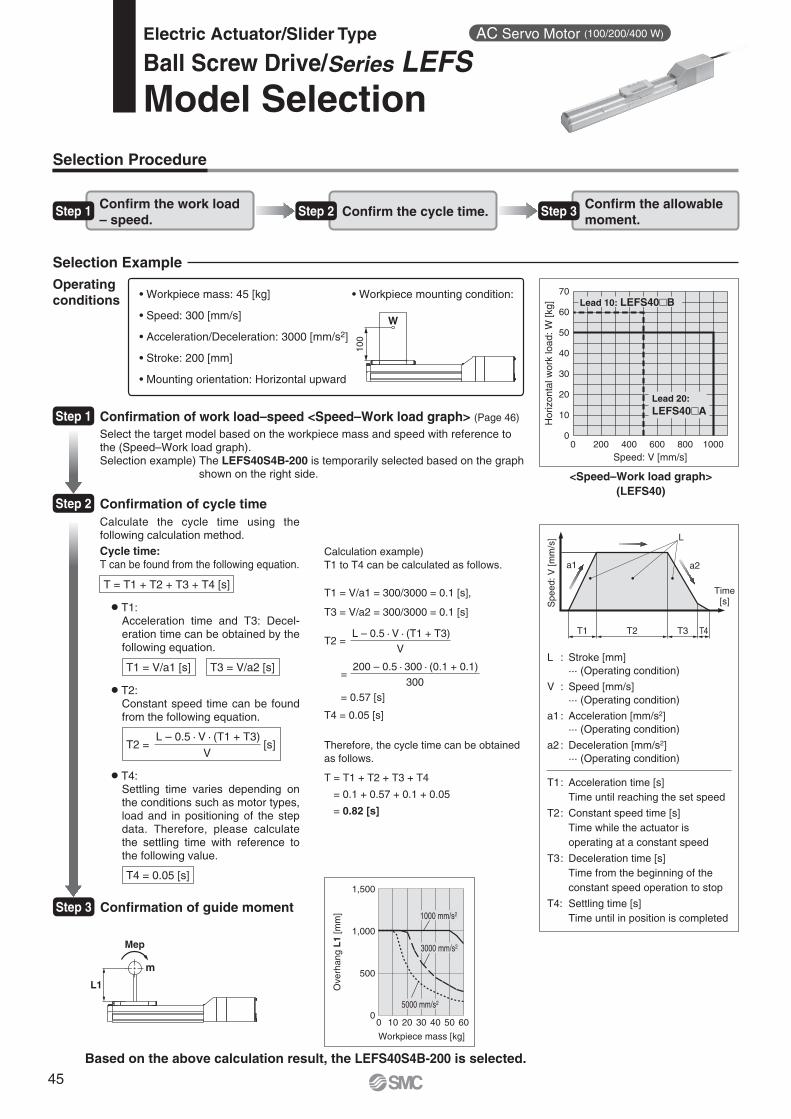
Hor
izon
tal w
ork
load
: W [k
g]
Speed: V [mm/s]
Workpiece mass [kg]
Ove
rhan
g L
1 [m
m]
L1
Mep
m
T1
a1 a2
L
T2 T3 T4
0 200 400 600 800 1000
70
60
50
40
30
20
10
0
Spe
ed: V
[mm
/s]
Time[s]
Selection Procedure
Step 1 Confirm the work load – speed.
Step 2 Confirm the cycle time. Step 3 Confirm the allowable moment.
100
W
Selection Example
2]
Operatingconditions
<Speed–Work load graph>(LEFS40)
Step 1
Step 2
Step 31000 mm/s2
3000 mm/s2
5000 mm/s2
Lead 20: LEFS40�A
Lead 10: LEFS40�B
0 10 20 30 40 50 60
1,500
1,000
500
0
(100/200/400 W)Electric Actuator/Slider Type
Ball Screw Drive/Series LEFS Model Selection
Confirmation of work load–speed <Speed–Work load graph> (Page 46)
Select the target model based on the workpiece mass and speed with reference to the (Speed–Work load graph).Selection example) The LEFS40S4B-200 is temporarily selected based on the graph shown on the right side.
Confirmation of cycle time
Cycle time:
T = T1 + T2 + T3 + T4 [s]
T1 = V/a1 [s] T3 = V/a2 [s]
T2 = [s]L – 0.5 · V · (T1 + T3)
V
� T4:Settling time varies depending on
load and in positioning of the step
the settling time with reference to
� T2:
� T1:-
eration time can be obtained by the
Confirmation of guide moment
T1 = V/a1 = 300/3000 = 0.1 [s],
T3 = V/a2 = 300/3000 = 0.1 [s]
T4 = 0.05 [s]
Therefore, the cycle time can be obtained as follows.
T = T1 + T2 + T3 + T4
= 0.1 + 0.57 + 0.1 + 0.05
= 0.82 [s]
T2 =
=
= 0.57 [s]
L – 0.5 · V · (T1 + T3)
V
200 – 0.5 · 300 · (0.1 + 0.1)
300
T4 = 0.05 [s]
Based on the above calculation result, the LEFS40S4B-200 is selected.
L : Stroke [mm] ··· (Operating condition)
V : Speed [mm/s] ··· (Operating condition)
2] ··· (Operating condition)
2] ··· (Operating condition)
operating at a constant speed
Time from the beginning of the constant speed operation to stop
T4: Settling time [s]
45

0 200 400 600 800 1000
70
60
50
40
30
20
10
0
0 200 400 600 800 1000
70
60
50
40
30
20
10
0
0 200 400 600 800 1000
70
60
50
40
30
20
10
0
0 200 400 600 800 1000
70
60
50
40
30
20
10
0
0 200 400 600 800 1000
70
60
50
40
30
20
10
0
0 200 400 600 800 1000
70
60
50
40
30
20
10
0
Hor
izon
tal w
ork
load
: W [k
g]
Speed: V [mm/s]
Ver
tical
wor
k lo
ad: W
[kg]
Speed: V [mm/s]
Hor
izon
tal w
ork
load
: W [k
g]
Speed: V [mm/s]
Ver
tical
wor
k lo
ad: W
[kg]
Speed: V [mm/s]
Hor
izon
tal w
ork
load
: W [k
g]
Speed: V [mm/s]
Ver
tical
wor
k lo
ad: W
[kg]
Speed: V [mm/s]
Speed–Work Load Graph (Guide)
LEFS25/Ball Screw Drive
LEFS40/Ball Screw Drive
LEFS32/Ball Screw Drive
Horizontal Vertical
Horizontal Vertical
Allowable Stroke Speed
LEFS25
LEFS32
LEFS40
Model
∗ When transferring load mass vertically, “Regeneration option” is required under the work load conditions shown below. Order “Regeneration option” separately. (Refer to page 63)
AC servomotor
100 W
/�40
200 W
/�60
400 W
/�60
Lead
(Motor rotation speed)
Symbol [mm]
A
B
12
6
to 100 to 200
900
450
(4500 rpm)
to 300
(3750 rpm)
1000
500
(3000 rpm)
to 400
1000
500
1000
500
1000
500
1000
500
to 500
Stroke [mm]
720
360
(3650 rpm)
1000
500
to 600
540
270
(2700 rpm)
800
400
(3000 rpm)
to 700
620
310
(2325 rpm)
940
470
(2820 rpm)
to 800
500
250
(1875 rpm)
760
380
(2280 rpm)
to 900
620
310
(1860 rpm)
to 1000
520
260
(1560 rpm)
(Motor rotation speed)
A
B
16
8
(Motor rotation speed)
A
B
20
10
Model
Lead
Vertical work load [kg]
Vertical work load conditions [kg]
A
8
Required Note)
B
15
A
10
Not required
B
20
A
15
Not required
B
30
20 or more
Note) For vertical transfer, “Regeneration option” is required regardless of load mass.
Lead 6: LEFS25�B Lead 12: LEFS25�ALead 6: LEFS25�B
Lead 12: LEFS25�A
Lead 8: LEFS32�B
Lead 16: LEFS32�A
Lead 10: LEFS40�B
Lead 20: LEFS40�ALead 10: LEFS40�B
Lead 20: LEFS40�A
Lead 8: LEFS32�BLead 16: LEFS32�A
∗ The allowable speed is limited depending on the stroke. Select it referring to “Allowable Stroke Speed” below.
Required Conditions for “Regeneration Option”
Horizontal Vertical
[mm/s]
LEFS25S26 LEFS32S3
7 LEFS40S48
Model Selection Series LEFS
Ser
vo M
otor
(24
VD
C)/
Ste
p M
otor
(S
ervo
/24
VD
C)
Mod
el S
elec
tion
Spec
ific P
roduc
t Prec
autio
nsA
C S
ervo
Mot
or
46
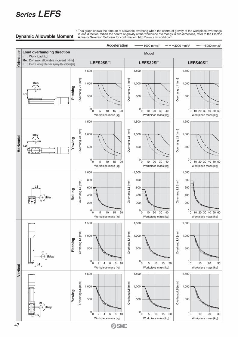
LEFS25S� LEFS32S� LEFS40S�
1,500
1,000
500
00 0 10 20 30 40
0 10 20 30 40
0 10 20 30 40
05 10 15 20
0 05 10 15 20
0 0 10 20 30 40 50 60
10 20 30 40 50 60
10 20 30 40 50 60
5 10 15 20
1,500
1,000
500
0
1,000
800
600
400
200
0
1,500
1,000
500
00 0 5 10 15 20
5 10 15 20
042 6 8 10
0 0 0 10 20 30
10 20 30
42 6 8 10
1,500
1,000
500
0
1,500
1,000
500
0
1,500
1,000
500
0
1,000
800
600
400
200
0
1,500
1,000
500
0
1,500
1,000
500
0
1,500
1,000
500
0
1,500
1,000
500
0
1,000
800
600
400
200
0
1,500
1,000
500
0
1,500
1,000
500
0
L1
L2
Mep
m
Mey
m
L3
Merm
L4
Mepm
L5
Meym
Dynamic Allowable Moment∗ This graph shows the amount of allowable overhang when the centre of gravity of the workpiece overhangs
in one direction. When the centre of gravity of the workpiece overhangs in two directions, refer to the ElectricActuator Selection Software for confirmation. http://www.smcworld.com
Acceleration 1000 mm/s2 3000 mm/s2 5000 mm/s2
Orie
ntat
ion Load overhanging direction
m : Work load [kg]Me : Dynamic allowable moment [N·m]L : Amount of overhang to the centre of gravity of the workpiece [mm]
Ver
tica
lH
ori
zon
tal
Model
Workpiece mass [kg]
Ove
rhan
g L
1 [m
m]
Pit
chin
gP
itch
ing
Yaw
ing
Yaw
ing
Ro
llin
g
Workpiece mass [kg]
Ove
rhan
g L
1 [m
m]
Workpiece mass [kg]
Ove
rhan
g L
1 [m
m]
Workpiece mass [kg]
Ove
rhan
g L
2 [m
m]
Workpiece mass [kg]
Ove
rhan
g L
2 [m
m]
Workpiece mass [kg]
Ove
rhan
g L
2 [m
m]
Workpiece mass [kg]
Ove
rhan
g L
3 [m
m]
Workpiece mass [kg]
Ove
rhan
g L
3 [m
m]
Workpiece mass [kg]
Ove
rhan
g L
3 [m
m]
Workpiece mass [kg]
Ove
rhan
g L
4 [m
m]
Workpiece mass [kg]
Ove
rhan
g L
4 [m
m]
Workpiece mass [kg]
Ove
rhan
g L
4 [m
m]
Workpiece mass [kg]
Ove
rhan
g L
5 [m
m]
Workpiece mass [kg]
Ove
rhan
g L
5 [m
m]
Workpiece mass [kg]
Ove
rhan
g L
5 [m
m]
Series LEFS
47
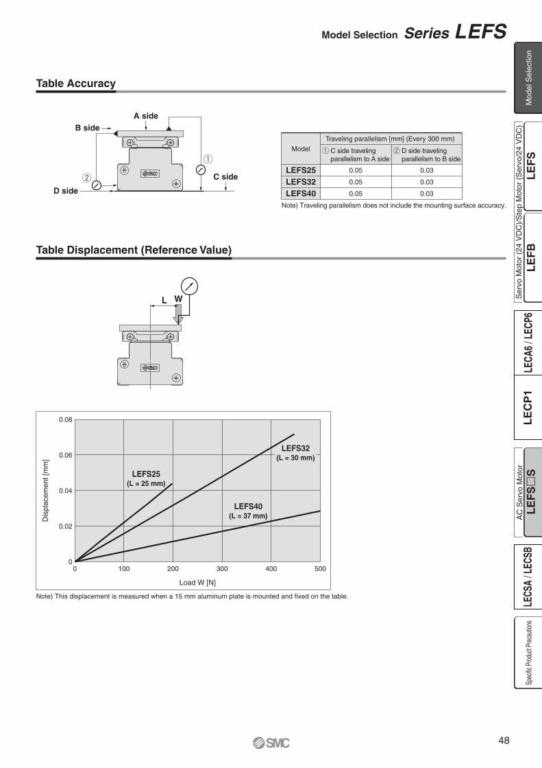
w
q
A side
C side
B side
D side
0.08
0.06
0.04
0.02
00 100 200 300 400 500
Dis
plac
emen
t [m
m]
WL
Load W [N]
Note) This displacement is measured when a 15 mm aluminum plate is mounted and fixed on the table.
LEFS25LEFS32LEFS40
Note) Traveling parallelism does not include the mounting surface accuracy.
0.05
0.05
0.05
0.03
0.03
0.03
LEFS25(L = 25 mm)
LEFS32(L = 30 mm)
LEFS40(L = 37 mm)
Table Accuracy
Model q C side travelingparallelism to A side
Traveling parallelism [mm] (Every 300 mm)
w D side travelingparallelism to B side
Table Displacement (Reference Value)
Model Selection Series LEFS
Ser
vo M
otor
(24
VD
C)/
Ste
p M
otor
(S
ervo
/24
VD
C)
Mod
el S
elec
tion
Spec
ific P
roduc
t Prec
autio
nsA
C S
ervo
Mot
or
48
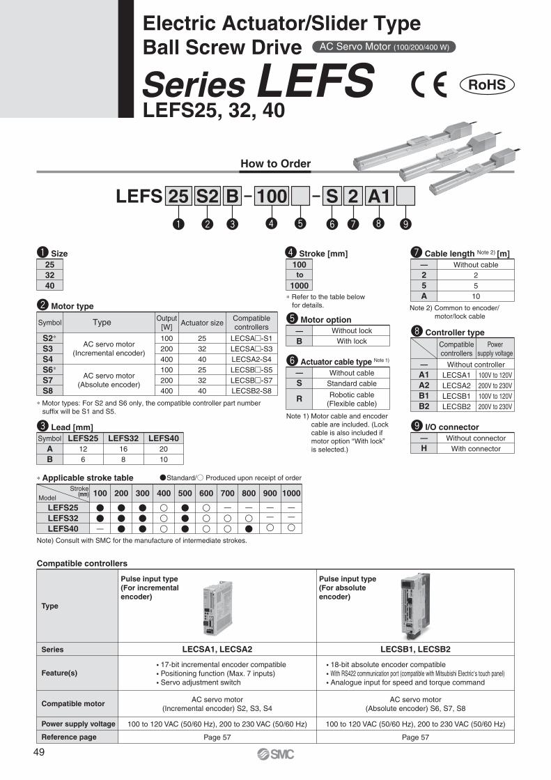
How to Order
LEFS25, 32, 40Series LEFS
LEFS 25 100B 2 A1
253240
AB
LEFS25126
LEFS32 LEFS40168
2010
Symbol
∗ Applicable stroke table
LEFS25LEFS32LEFS40
��—
Stroke(mm)
Model100
���
200
���
300
400
���
500
600
—
700
—
�
800
——
900
——
1000
—B
Without lockWith lock
Sq w e r t y u i o
Note) Consult with SMC for the manufacture of intermediate strokes.
∗ Motor types: For S2 and S6 only, the compatible controller part number suffix will be S1 and S5.
q Size
e Lead [mm]
t Motor option
100
1000to
∗ Refer to the table below for details.
r Stroke [mm]—25A
Without cable2510
—S
R
Without cableStandard cable
Robotic cable(Flexible cable)
Note 1) Motor cable and encoder cable are included. (Lock cable is also included if motor option “With lock” is selected.)
Note 2) Common to encoder/motor/lock cable
y Actuator cable type Note 1)
u Cable length Note 2) [m]
S2
Compatible controllers
Type
Series
Feature(s)
Compatible motor
LECSA1, LECSA2
� 17-bit incremental encoder compatible� Positioning function (Max. 7 inputs)� Servo adjustment switch
LECSB1, LECSB2
AC servo motor(Incremental encoder) S2, S3, S4
AC servo motor(Absolute encoder) S6, S7, S8
� 18-bit absolute encoder compatible� With RS422 communication port (compatible with Mitsubishi Electric,s touch panel)� Analogue input for speed and torque command
100 to 120 VAC (50/60 Hz), 200 to 230 VAC (50/60 Hz)
Page 57
100 to 120 VAC (50/60 Hz), 200 to 230 VAC (50/60 Hz)
Page 57
Pulse input type(For incrementalencoder)
Pulse input type(For absoluteencoder)
Power supply voltage
Reference page
S2∗
S3S4S6∗
S7S8
100200400100200400
253240253240
Symbol Type Actuator sizeOutput
[W]
AC servo motor(Incremental encoder)
AC servo motor(Absolute encoder)
w Motor type
LECSA2-S4
LECSB2-S8
LECSA�-S1LECSA�-S3
Compatiblecontrollers
LECSB�-S5LECSB�-S7
—H
Without connectorWith connector
—A1A2B1B2
Without controller
i Controller type
o I/O connector
LECSA1LECSA2LECSB1LECSB2
100V to 120V200V to 230V100V to 120V200V to 230V
Powersupply voltage
Compatiblecontrollers
AC Servo Motor (100/200/400 W)
RoHS
Standard/ Produced upon receipt of order
Electric Actuator/Slider TypeBall Screw Drive
49

Specifications
Note 1) Consult with SMC for the manufacture of intermediate strokes other than those specified on the above.Note 2) For details, refer to “Speed–Work Load Graph (Guide)” on page 46.Note 3) The allowable speed will change depending on the stroke.Note 4) Impact resistance: No malfunction occurred when the actuator was tested with a drop tester in both an axial direction and a perpendicular direction
to the lead screw. (Test was performed with the actuator in the initial state.)Vibration resistance: No malfunction occurred in a test ranging between 45 to 2000 Hz. Test was performed in both an axial direction and a perpendicular direction to the lead screw. (Test was performed with the actuator in the initial state.)
Note 5) Only when motor option “With lock” is selected.Note 6) For an actuator with lock, add the power consumption for the lock.
100, 200, 300, (400)500, (600)
100 W/�40 200 W/�60 400 W/�60
20
8
900
720
540—
—
——
12 6 16 8 20 10
5000
±0.02
50/20
Ball screw
Linear guide
5 to 40
90 or less (No condensation)
AC servo motor (100/200 VAC)
Non-magnetizing operation type
24 VDC
20
15
450
360
270—
—
——
LEFS25, 32, 40 AC Servo Motor (100/200/400 W)Model
Ele
ctri
csp
ecif
icat
ion
s
Stroke [mm] Note 1)
Max. acceleration/deceleration [mm/s2]
Positioning repeatability [mm]
Lead [mm]
Impact/Vibration resistance [m/s2] Note 4)
Actuation type
Guide type
Operating temperature range [°C]
Operating humidity range [%RH]
Motor output/Size
Motor type
Encoder
Type Note 5)
Holding force [N]
Power consumption at 20C [W] Note 6)
Rated voltage [V]
131 255 197 385 330
6.3 7.9 7.9
660
100, 200, 300, (400)500, (600), (700), (800)
40
10
1000
1000
800
620
500
——
45
20
500
500
400
310
250
——
200, 300, (400), 500(600), (700), 800, (900)
(1000)
50
15
1000
1000
1000
940
760
620
520
60
30
500
500
500
470
380
310
260
Horizontal
Vertical
to 400
401 to 500
501 to 600
601 to 700
701 to 800
801 to 900
901 to 1000
0—10%
Work load [kg] Note 2)
Max. speed Note 3)
[mm/s]Stroke range
Motor type S2, S3, S4: Incremental 17-bit encoder (Resolution: 131072 p/rev)Motor type S6, S7, S8: Absolute 18-bit encoder(Resolution: 262144 p/rev)
Lo
ck u
nit
spec
ific
atio
ns
Weight
0.70
Model LEFS32Stroke [mm]
Product weight [kg]
Additional weight with lock [kg]
1003.60
2004.00
3004.40
5005.20
(800)6.40
(700)6.00
(600)5.60
(400)4.80
Model
Stroke [mm]
Product weight [kg]
Additional weight with lock [kg]
LEFS402006.20
3006.75
5007.90
(400)7.35
8009.55
(900)10.15
(1000)10.70
(700)9.00
(600)8.350.70
Model
Stroke [mm]
Product weight [kg]
Additional weight with lock [kg]
1002.20
(400)3.05
3002.75
2002.50
LEFS255003.30
(600)3.60
0.35
Act
uat
or
spec
ific
atio
ns
LEFS25S26 LEFS32S3
7 LEFS40S48
Series LEFSElectric Actuator/Slider TypeBall Screw Drive
Ser
vo M
otor
(24
VD
C)/
Ste
p M
otor
(S
ervo
/24
VD
C)
Mod
el S
elec
tion
Spec
ific P
roduc
t Prec
autio
nsA
C S
ervo
Mot
or
50

A-A
i
w
!6 !4
!7 !7!8 !1 !3q u t y u o
A
A!9 r e @0 !0 !2 !5
No. Description Material Note
1
2
3
4
5
6
7
8
9
10
Body
Rail guide
Ball screw shaft
Ball screw nut
Table
Blanking plate
Seal band stopper
Housing A
Housing B
Bearing stopper
Aluminum alloy
—
—
—
Aluminum alloy
Aluminum alloy
Synthetic resin
Aluminum die-casted
Aluminum die-casted
Aluminum alloy
Anodised
Anodised
Anodised
Coating
Coating
No. Description Material Note
11
12
13
14
15
16
17
18
19
20
Motor mount
Coupling
Motor cover
Motor end cover
Motor
Grommet
Band stopper
Dust seal band
Bearing
Bearing
Aluminum alloy
—
Aluminum alloy
Aluminum alloy—
NBR
Stainless steel
Stainless steel
—
—
Coating
Anodised
Anodised
Component Parts
Construction
Series LEFS
51

Encoder cable (ø7)
Lock cable (ø4.5) Power supply cable (ø6)
209
Motor option: With lock
6
6.5
2466
38
57.8
n x ø4.5
4
10
48
B
D x 100 (= E)
120
35
3.550
(102)
64
38
45
Encoder cable (ø7)
Power supply cable (ø6)Body mounting Note 1)
reference plane
Encoder Z phase detecting position Note 3)
Encoder Z phase detecting position Note 3)
(56)
(52) A (Table travel distance): Stroke+6)Note 2)
(4)
52
2±1
Stroke (54)
38.5 48
10
169
(2.2)(L)
231
Motor option: With lock
6.5
7.5
70
48
3084
M4 x 0.7thread depth 8 (F.G. terminal)
60
n x ø5.5
BD x 100 (= E)
150
15 15
6
60
44
42
5.5
+0.0300
70
(122)
Power supply cable (ø6)
Encoder cable (ø7)Body mounting Note 1)
reference plane
(2.2)(L)201(62)
(66)
A (Table travel distance: Stroke+6)Note 2)
(4)
62
2±1
Stroke
10
(64)
ø3H9depth 3
( ) +0.0250
3H9depth 3
( ) +0.0250
3H9depth 3
( ) +0.0250
4 x M5 x 0.8thread depth 8.5
M4 x 0.7thread depth 8(F.G. terminal)
ø5H9depth 5
( )
4 x M6 x 1thread depth 9.5
( ) 5H9depth 5
+0.0300
( ) 5H9depth 5
+0.0300
Encoder cable (ø7)
Lock cable (ø4.5) Power supply cable (ø6)
LEFS25
Dimensions: Ball Screw Drive
Note 1) When mounting the electric actuator using the body mounting reference plane, set the height of the opposite surface or pin to 3 mm or more because of R chamfering. (Recommended height: 5 mm)
Note 2) Distance within which the table can move when it returns to origin. Make sure a workpiece mounted on the table does not interfere with the work pieces and facilities around the table.
Note 3) The Z phase first detecting position from the stroke end of the motor side.
LEFS25��-100-����LEFS25��-100B-����LEFS25��-200-����LEFS25��-200B-����LEFS25��-300-����LEFS25��-300B-����
Model L389429489529589629
A
210
310
410
106
206
306
B
4
6
8
n
—
2
3
D
—
240
360
E[mm]
LEFS25��-400-���� LEFS25��-400B-���� LEFS25��-500-���� LEFS25��-500B-���� LEFS25��-600-���� LEFS25��-600B-����
Model L689729789829889929
A
510
610
710
406
506
606
B
8
10
12
n
3
4
5
D
360
480
600
E[mm]
LEFS32
Note 1) When mounting the electric actuator using the body mounting reference plane, set the height of the opposite surface or pin to 3 mm or more because of R chamfering. (Recommended height: 5 mm)
Note 2) Distance within which the table can move. Make sure a workpiece mounted on the table does not interfere with the work pieces and facilities around the table.
Note 3) The Z phase first detecting position from the stroke end of the motor side.
[mm]
LEFS32��-100-����LEFS32��-100B-����LEFS32��-200-����LEFS32��-200B-����LEFS32��-300-����LEFS32��-300B-����LEFS32��-400-����LEFS32��-400B-����
Model L441471541571641671741771
A
230
330
430
530
106
206
306
406
B
4
6
6
8
n
—
2
2
3
D
—
300
300
450
E[mm]
LEFS32��-500-����LEFS32��-500B-����LEFS32��-600-����LEFS32��-600B-����LEFS32��-700-����LEFS32��-700B-����LEFS32��-800-����LEFS32��-800B-����
Model L 841 871 941 9711041107111411171
A
630
730
830
930
506
606
706
806
B
10
10
12
14
n
4
4
5
6
D
600
600
750
900
E
60
46.8
Series LEFSElectric Actuator/Slider TypeBall Screw Drive
Ser
vo M
otor
(24
VD
C)/
Ste
p M
otor
(S
ervo
/24
VD
C)
Mod
el S
elec
tion
Spec
ific P
roduc
t Prec
autio
nsA
C S
ervo
Mot
or
52
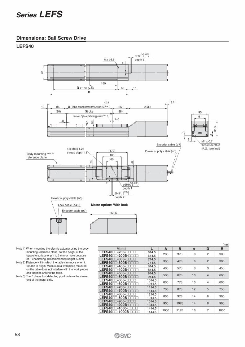
Encoder Z phase detecting position Note 3)
Lock cable (ø4.5)
Power supply cable (ø6)
Encoder cable (ø7)253.5
Motor option: With lock
BD x 150 (=E)
150
60 15
76
n x ø6.6
7
7
74 58
(170)
106
60
Power supply cable (ø6)
Encoder cable (ø7)
8
8
61
90
31
85.5
(3.1)
A (Table travel distance: Stroke+6)Note 2)86 86
(4) 2±1
(90)
13
(L)
Stroke (88)
223.5
53.8 68
4 x M8 x 1.25thread depth 13
ø6H9depth 7
( )+0.030 0
6H9depth 7
( )+0.030 0
6H9depth 6
( )+0.030 0
M4 x 0.7thread depth 8(F.G. terminal)
Dimensions: Ball Screw Drive
LEFS40
Note 1) When mounting the electric actuator using the body mounting reference plane, set the height of the opposite surface or pin to 3 mm or more because of R chamfering. (Recommended height: 5 mm)
Note 2) Distance within which the table can move when it returns to origin. Make sure a workpiece mounted on the table does not interfere with the work pieces and facilities around the table.
Note 3) The Z phase first detecting position from the stroke end of the motor side.
[mm]
LEFS40��-200-����LEFS40��-200B-����LEFS40��-300-����LEFS40��-300B-����LEFS40��-400-����LEFS40��-400B-����LEFS40��-500-����LEFS40��-500B-����LEFS40��-600-����LEFS40��-600B-����LEFS40��-700-����LEFS40��-700B-����LEFS40��-800-����LEFS40��-800B-����LEFS40��-900-����LEFS40��-900B-����LEFS40��-1000-����LEFS40��-1000B-����
Model L614.5644.5714.5744.5814.5844.5914.5944.51014.51044.51114.51144.51214.51244.51314.51344.51414.51444.5
A
378
478
578
678
778
878
978
1078
1178
206
306
406
506
606
706
806
906
1006
B
6
6
8
10
10
12
14
14
16
n
2
2
3
4
4
5
6
6
7
D
300
300
450
600
600
750
900
900
1050
E
Body mounting Note 1)
reference plane
Series LEFS
53
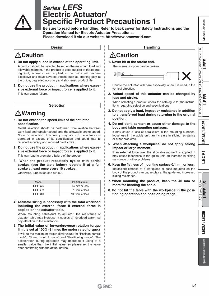
Design
Caution1. Do not apply a load in excess of the operating limit.
A product should be selected based on the maximum load and allowable moment. If the product is used outside of the operat-ing limit, eccentric load applied to the guide will become excessive and have adverse effects such as creating play at the guide, degraded accuracy and shortened product life.
2. Do not use the product in applications where exces-sive external force or impact force is applied to it.This can cause failure.
Selection
Warning1. Do not exceed the speed limit of the actuator
specification.Model selection should be performed from relation between work load and transfer speed, and the allowable stroke speed. Noise or reduction of accuracy may occur if the actuator is operated in excess of its specification and could lead to reduced accuracy and reduced product file.
2. Do not use the product in applications where exces-sive external force or impact force is applied to it.This can lead to premature failure of the product.
3. When the product repeatedly cycles with partial strokes (see the table below), operate it at a full stroke at least once every 10 strokes.Otherwise, lubrication can run out.
4. Actuator sizing is necessary with the total workload including the external force if external force is applied on the actuator table.When mounting cable-duct to actuator, the resistance of actuator table may increase. It causes an overload alarm, so pay attention to the resistance.
5. The initial value of forward/reverse rotation torque limit is set at 100% (3 times the motor rated torque.)It will be the maximum torque (limit value) for “Position control mode”, “Speed control mode” and “Positioning mode”. The acceleration during operation may decrease if using at a smaller value than the initial value, so please set the value after confirming with the actual device.
Handling
Caution1. Never hit at the stroke end.
The internal stopper can be broken.
Handle the actuator with care especially when it is used in the vertical direction.
2. Actual speed of this actuator can be changed by load and stroke.When selecting a product, check the catalogue for the instruc-tions regarding selection and specifications.
3. Do not apply a load, impact or resistance in addition to a transferred load during returning to the original position.
4. Do not dent, scratch or cause other damage to the body and table mounting surfaces.It may cause a loss of parallelism in the mounting surfaces, looseness in the guide unit, an increase in sliding resistance or other problems.
5. When attaching a workpiece, do not apply strong impact or large moment.If an external force over the allowable moment is applied, it may cause looseness in the guide unit, an increase in sliding resistance or other problems.
6. Keep the flatness of mounting surface 0.1 mm or less.Insufficient flatness of a workpiece or base mounted on the body of the product can cause play at the guide and increased sliding resistance.
7. When mounting the product, keep the 40 mm or more for bending the cable.
8. Do not hit the table with the workpiece in the posi-tioning operation and positioning range.
Model
LEFS25LEFS32LEFS40
Partial stroke
65 mm or less
70 mm or less
105 mm or less
Series LEFSElectric Actuator/Specific Product Precautions 1Be sure to read before handling. Refer to back cover for Safety Instructions and the Operation Manual for Electric Actuator Precautions.Please download it via our website. http://www.smcworld.com
Ser
vo M
otor
(24
VD
C)/
Ste
p M
otor
(S
ervo
/24
VD
C)
Mod
el S
elec
tion
Spec
ific P
roduc
t Prec
autio
nsA
C S
ervo
Mot
or
54

LEFS25LEFS32LEFS40
Model
M5 x 0.8M6 x 1
M8 x 1.25
Bolt
3.05.212.5
Max. tighteningtorque (N·m)
89
14
L (Max. screw-indepth mm)
To prevent the workpiece fixing bolts from touching the body, use bolts that are 0.5 mm or shorter than the maximum screw-in depth. If long bolts are used, they can touch the body and malfunction, etc.
Workpiece fixed
Body fixed
LEFS25LEFS32LEFS40
Model
M4M5M6
Bolt
4.55.56.6
øA(mm)
243031
L(mm)
øA
L
L
10. Do not operate by fixing the table and moving the actuator body.
11. Check the specifications for the minimum speed of each actuator.Otherwise, unexpected malfunctions, such as knocking, may occur.
Maintenance
WarningMaintenance frequency
Perform maintenance according to the table below.
� Items for visual appearance check1. Loose set screws, Abnormal dirt2. Check of flaw and cable joint3. Vibration, Noise
� Items for internal check1. Lubricant condition on moving parts.2. Loose or mechanical play in fixed parts or fixing screws.
Inspection before daily operation
Inspection every 6 months/1000 km/5 million cycles∗
�
Appearance check
—
Internal checkFrequency
� �
∗ Select whichever comes sooner.
Series LEFSElectric Actuator/Specific Product Precautions 2Be sure to read before handling. Refer to back cover for Safety Instructions and the Operation Manual for Electric Actuator Precautions.Please download it via our website. http://www.smcworld.com
Handling
Caution9. When mounting the product, use screws with adequate
length and tighten them with adequate torque.Tightening the screws with a higher torque than recommended may malfunction, whilst the tightening with a lower torque can cause the displacement of the mounting position or in extreme conditions the actuator could become detached from its mounting position.
55

Incremental encoder compatible Series LECSA
Controller
Controller
Absolute encoder compatible Series LECSB
PLC
Electric actuator
Power supply for I/O signal
24 VDC
Power supply for I/O signal
24 VDC
Power supplySingle phase100 to 120 VAC (50/60 Hz)200 to 230 VAC (50/60 Hz)
Supplied by customer
Analog monitor outputRS-422 communication
Battery (included)
PC
MR ConfiguratorSetup software
Supplied by customer
PLCSupplied by customer
Electric actuator
Power supply
Single phase100 to 120 VAC (50/60 Hz)200 to 230 VAC (50/60 Hz)
Three phase200 to 230 VAC (50/60 Hz)
Supplied by customer
Control circuit power supply24 VDC
Regenerationoption
USB cable
USB cable
PC
MR ConfiguratorSetup software
Regenerationoption
Series LECSAIncremental Type
Series LECSBAbsolute Type
AC Servo Motor Controller(Pulse Input Type)
Ser
vo M
otor
(24
VD
C)/
Ste
p M
otor
(S
ervo
/24
VD
C)
Mod
el S
elec
tion
Spec
ific P
roduc
t Prec
autio
nsA
C S
ervo
Mot
or
56
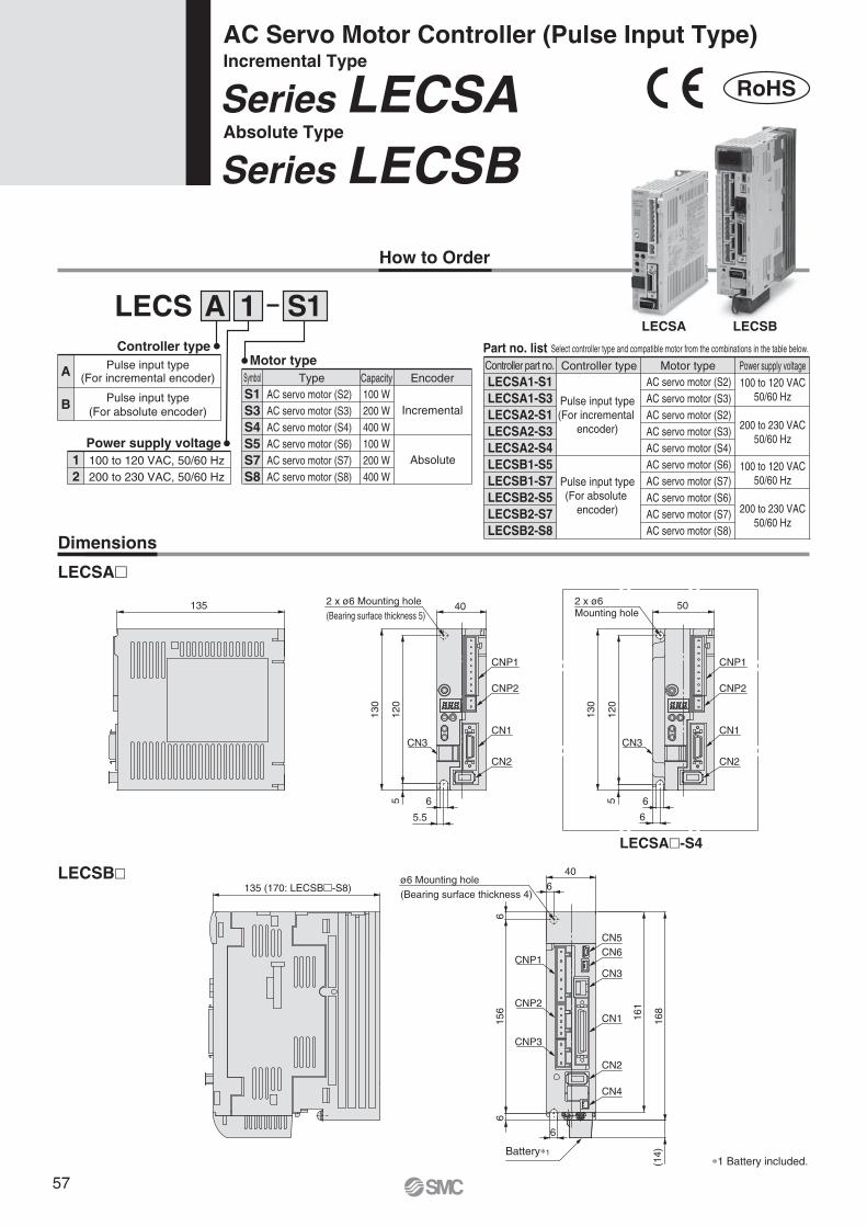
How to Order
Series LECSBAbsolute TypeSeries LECSAIncremental TypeAC Servo Motor Controller (Pulse Input Type)
Dimensions
LECSA�
LECSA�-S4
LECSB�
LECS 1A S1Controller type
Motor type
Power supply voltage
S1S3S4S5S7S8
TypeAC servo motor (S2)AC servo motor (S3)AC servo motor (S4)AC servo motor (S6)AC servo motor (S7)AC servo motor (S8)
Capacity100 W200 W400 W100 W200 W400 W
Encoder
Incremental
Absolute
Symbol
Select controller type and compatible motor from the combinations in the table below.Part no. list
LECSA1-S1LECSA1-S3LECSA2-S1LECSA2-S3LECSA2-S4LECSB1-S5LECSB1-S7LECSB2-S5LECSB2-S7LECSB2-S8
Controller type Motor type
Pulse input type(For incremental
encoder)
Pulse input type(For absolute
encoder)
AC servo motor (S2)AC servo motor (S3)AC servo motor (S2)AC servo motor (S3)AC servo motor (S4)AC servo motor (S6)AC servo motor (S7)AC servo motor (S6)AC servo motor (S7)AC servo motor (S8)
Power supply voltage
100 to 120 VAC50/60 Hz
200 to 230 VAC50/60 Hz
100 to 120 VAC50/60 Hz
200 to 230 VAC50/60 Hz
Controller part no.A
B Pulse input type(For absolute encoder)
Pulse input type(For incremental encoder)
12
100 to 120 VAC, 50/60 Hz200 to 230 VAC, 50/60 Hz
6
5.5
5 5
130
120
40135 2 x ø6 Mounting hole(Bearing surface thickness 5)
∗1 Battery included.
2 x ø6 Mounting hole
ø6 Mounting hole(Bearing surface thickness 4)
CN3 CN3
CNP3
CNP2
CNP1
CN2
CN1
CN3
Battery∗1
CN1
CN2
CN4
CN6CN5
CNP2
CNP1
CN2
CN1
CNP2
CNP1
6
130
120
6
50
(14)
156
66
6
161
168
40
135 (170: LECSB�-S8)
LECSA LECSB
6
RoHS
57
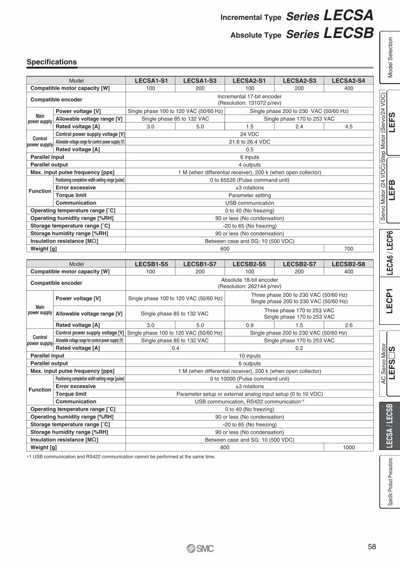
1.5 2.4
3.0 5.0 0.9 2.61.5
Model LECSA1-S1 LECSA1-S3 LECSA2-S1 LECSA2-S3 LECSA2-S4Compatible motor capacity [W]
Compatible encoder
Power voltage [V]Allowable voltage range [V]Rated voltage [A]Control power supply voltage [V]Allowable voltage range for control power supply [V]Rated voltage [A]
Positioning completion width setting range [pulse]Error excessiveTorque limitCommunication
Parallel inputParallel outputMax. input pulse frequency [pps]
Operating temperature range [˚C]Operating humidity range [%RH]Storage temperature range [˚C]Storage humidity range [%RH]Insulation resistance [M ]Weight [g]
Mainpower supply
Function
Controlpower supply
100 200 100 400200
3.0 5.0
Single phase 100 to 120 VAC (50/60 Hz)Single phase 85 to 132 VAC
24 VDC21.6 to 26.4 VDC
0.56 inputs
4 outputs1 M (when differential receiver), 200 k (when open collector)
0 to 65535 (Pulse command unit)±3 rotations
Parameter settingUSB communication0 to 40 (No freezing)
90 or less (No condensation)–20 to 65 (No freezing)
90 or less (No condensation)Between case and SG: 10 (500 VDC)
4.5
600 700
Single phase 200 to 230 VAC (50/60 Hz)Single phase 170 to 253 VAC
Incremental 17-bit encoder(Resolution: 131072 p/rev)
Model LECSB1-S5 LECSB1-S7 LECSB2-S5 LECSB2-S7 LECSB2-S8Compatible motor capacity [W]
Compatible encoder
Power voltage [V]
Allowable voltage range [V]
Rated voltage [A]Control power supply voltage [V]Allowable voltage range for control power supply [V]Rated voltage [A]
Positioning completion width setting range [pulse]Error excessiveTorque limitCommunication
Parallel inputParallel outputMax. input pulse frequency [pps]
Operating temperature range [˚C]Operating humidity range [%RH]Storage temperature range [˚C]Storage humidity range [%RH]Insulation resistance [M ]Weight [g]
Mainpower supply
Function
Controlpower supply
100 200 100 400200
Single phase 100 to 120 VAC (50/60 Hz)
Single phase 85 to 132 VAC
10 inputs6 outputs
1 M (when differential receiver), 200 k (when open collector)0 to 10000 (Pulse command unit)
±3 rotationsParameter setup or external analog input setup (0 to 10 VDC)
USB communication, RS422 communication∗1
0 to 40 (No freezing)90 or less (No condensation)
–20 to 65 (No freezing)90 or less (No condensation)
Between case and SG: 10 (500 VDC)
Single phase 100 to 120 VAC (50/60 Hz) Single phase 85 to 132 VAC
0.4
Single phase 200 to 230 VAC (50/60 Hz) Single phase 170 to 253 VAC
0.2
1000800
Three phase 200 to 230 VAC (50/60 Hz)Single phase 200 to 230 VAC (50/60 Hz)
Three phase 170 to 253 VACSingle phase 170 to 253 VAC
Absolute 18-bit encoder(Resolution: 262144 p/rev)
∗1 USB communication and RS422 communication cannot be performed at the same time.
Specifications
Incremental Type Series LECSAAbsolute Type Series LECSB
Ser
vo M
otor
(24
VD
C)/
Ste
p M
otor
(S
ervo
/24
VD
C)
Mod
el S
elec
tion
Spec
ific P
roduc
t Prec
autio
nsA
C S
ervo
Mot
or
58

Power Supply Wiring Example: LECSA
LECSA�-�
Terminal name Function Function details
L1 L1
L2
P
C
U
V
W
24V
0V
L2
P
C
UVW
Main circuit power supply
Regeneration option
Servo motor power (U)Servo motor power (V)Servo motor power (W)
Protective earth (PE)
Connect the main circuit power supply.LECSA1: Single phase 100 to 120 VAC, 50/60 HzLECSA2: Single phase 200 to 230 VAC, 50/60 Hz
Terminal to connect regeneration optionLECSA�-S1: No need for connectionLECSA�-S3, S4: Connected at time of shipping.∗ If regeneration option is required for “Model Selection”,connect to this terminal.
Connect to motor cable (U, V, W)
Should be grounded via servo motor’s earth terminal and control panel’s protective earth (PE) after connecting them.
Terminal name Function Function details
24V
0V
Control circuit power supply (24V)
Control circuit power supply (0V)
24V side of the control circuit power supply (24 VDC) which supplies the controller.
0V side of the control circuit power supply (24 VDC) which supplies the controller.
Main circuit power supplySingle phase 200 to 230 VACorSingle phase 100 to 120 VAC
Control circuit power supply24 VDC
L1
CNP1NFB MC
Built-in regenerative resistor
Regeneration option
CN2
L2
P
U
V
W
U MotorV
WM
C
+24 V
CNP2
0 V
DetectorCircuit protector
Main Circuit Power Supply Connector: CNP1 ∗Accessory
Control Circuit Power Supply Connector: CNP2 ∗Accessory
Series LECSASeries LECSB
59

Main Circuit Power Supply Connector: CNP1Terminal name Function Function details
L1
L2
L3
NP1
P2
PCD
L11
L21
L1
L2
L3
N
P1
P2
P
C
D
L11
L21
Main circuit power supply
Regenerative converter
DC reactor
Regeneration option
Control circuit power supply (24 V)Control circuit power supply (0 V)
Connect the main circuit power supply.LECSB1: Single phase 100 to 120 VAC, 50/60 Hz Connection terminal: L1,L2
LECSB2: Single phase 200 to 230 VAC, 50/60 Hz Connection terminal: L1,L2
Three phase 200 to 230 VAC, 50/60 Hz Connection terminal: L1,L2,L3
Do not connect.
Connect between P1 and P2. (Connected at time of shipping.)
Connect between P and D. (Connected at time of shipping.)∗ If regeneration option is required for “Model Selection”,connect to this terminal.
Terminal name Function Function details
∗Accessory
Control Circuit Power Supply Connector: CNP2 ∗Accessory
Power Supply Wiring Example: LECSB
LECSB1-�
24V side of the control circuit power supply (24 VDC) which supplies the controller.0V side of the control circuit power supply (24 VDC) which supplies the controller.
UVW
Servo motor power (U)Servo motor power (V)Servo motor power (W)
Connect to motor cable (U, V, W)
Terminal name Function Function details
Motor Connector: CNP3 ∗Accessory
U
V
W
LECSB2-�For three phase 200 VAC
Three phase200 to 230VAC
L1
CNP1NFB MCCNP3
PE
CN2
L2
P1
P2
L3
U
V
W
U MotorV
WM
N (–)
P (+)
CNP2
C
L21
D
L11
For single phase 200 VAC
Note) For single phase 200 to 230 VAC, power supply should be connected to L1 and L2 terminals, with nothing connected to L3.
Detector
Single phase200 to 230VAC
L1
CNP1NFB MCCNP3
PE
CN2
L2
P1
P2
L3
U
V
W
U MotorV
WM
N
P
CNP2
C
L21
D
L11Detector
Single phase100 to 120 VAC
L1
CNP1NFB MCCNP3
PE
CN2
Open
P1
P2
L2
U
V
W
U MotorV
WM
N
P
CNP2
C
L21
D
L11Detector
Regeneration option
Regeneration option Regeneration option
Incremental Type Series LECSAAbsolute Type Series LECSB
Ser
vo M
otor
(24
VD
C)/
Ste
p M
otor
(S
ervo
/24
VD
C)
Mod
el S
elec
tion
Spec
ific P
roduc
t Prec
autio
nsA
C S
ervo
Mot
or
60

Control Signal Wiring Example: LECSA
LECSA�-�
Note 1) For preventing electric shock, be sure to connect the main circuit power supply connector for the servo amplifier (CNP1),s protective earth (PE)
terminal to the control panel,s protective earth (PE).
Note 2) For interface use, supply 24 VDC ±10% 200 mA using an external source. 200 mA is the value when all I/O command signals are used and reducing the number of inputs/outputs can decrease current capacity. Refer to “Operation Manual” for required current for interface.
Note 3) The failure (ALM) is ON during normal conditions. When it is OFF (alarm occurs), stop the sequencer signal using the sequence program.Note 4) The same name signals are connected inside the servo amplifier.Note 5) For command pulse input with an open collector method. When a positioning unit loaded with a differential line driver method is used, it is 10 m or
less.
FX3U-��MT/ES (Manufactured by Mitsubishi Electric)
PLC
CN3
CNP1
Sequencer power supply
PE
S/S
24V
0V
L.
N
S/SY000
COM1
Y010
COM3
COM2
X���
X���X���
Y004
LECSA
24 VDC
CN1
DICOM
OPC
DOCOM
PP
NP
CR
RD
LG
SD
INP
OP
Note 4)
Note 4)
Note 4)
Note 2)CN1
CN1
USB cable
10 m or less
2 m or less Note 5)
10 m or less
PCLEC-MR-SETUP221
Note 1)
1
2
13
23
25
5
11
14
Plate
10
21
9
12
15
Plate
20
ALM
EM1Forced stop
Servo ON
Reset
Forward rotation stroke end
Reverse rotation stroke end
8
SON 4
RES 3
LSP 6
LSN 7
MBR
LA
16 LAR
17 LB
18 LBR
19 LZ
SD
LZR
14 LG
Failure Note 3)
Electromagnetic brake interlock
A phase pulse detector(Differential line driver)
B phase pulse detector(Differential line driver)
Z phase pulse detector(Differential line driver)
Control common
RA1
RA2
+
Series LECSASeries LECSB
61

Control Signal Wiring Example: LECSB
LECSB�-�
Note 1) For preventing electric shock, be sure to connect the servo amplifier,s protective earth (PE) terminal to the control panel
,s protective earth (PE).
Note 2) For interface use, supply 24 VDC ±10% 300 mA using an external source.Note 3) The failure (ALM) is ON during normal conditions. When it is OFF (alarm occurs), stop the sequencer signal using the sequence program.Note 4) The same name signals are connected inside the servo amplifier.Note 5) For command pulse input with a differential line driver method. For open collector method, it is 2 m or less.
Positioning unitQD75D (Manufactured by
Mitsubishi Electric)
CN5
PE
CLEARCOM
CLEAR
RDYCOM
READY
PULSE F +
PULSE F –
S/S
PG0
PG0 COM
LECSB
24 VDC Note 2)
CN1
DICOM
DOCOM
CR
PP
NG
LG
LZ
SD
Note 4)
CN1Note 4)
CN1
CN6Note 4)
USB cable
2 m or less
10 m or less
10 m or less Note 5)
2 m or less
10 m or less
Note 4)
Note 1)
20
46
41
10
PG 11
NP 35
36
3
LZR 9
8
Plate
21
48
Plate
33
DICOM
EMGEmergency stop
Servo ON
Reset
Proportion control
External torque limit selection
Forward rotation stroke end
Reverse rotation stroke end
Analog torque limit+10 V/Maximum torque
Upper limit setting
42
SON 15
RES 19
PC 17
TL 18
LSP 43
LSN 44
DOCOM 47
P15R 1
TLA 27
LG 28
SD plate
ALM
23 ZSP
25 TLC
24 INP
4 LA
5 LAR
6 LB
7 LBR
SD
OP
34 LG
1 P15R
Failure Note 3)
Zero speed detection
Torque limiting
Positioning completion
A phase pulse detector(Differential line driver)
B phase pulse detector(Differential line driver)
Z phase pulse detector(Open collector)
Control common
Control common
RA1
RA2
RA3
2 m or less
1 LG
3 MO1
2 MO2 Analog monitor 2
Analog monitor 1
±10 VDC
±10 VDC
RA4
PULSE R +
PULSE R –
14
13
12
11
15
16
10
9
17
18
RD 49
+
PCLEC-MR-SETUP221
Incremental Type Series LECSAAbsolute Type Series LECSB
Ser
vo M
otor
(24
VD
C)/
Ste
p M
otor
(S
ervo
/24
VD
C)
Mod
el S
elec
tion
Spec
ific P
roduc
t Prec
autio
nsA
C S
ervo
Mot
or
62

Options
Motor cable, Lock cable, Encoder cable
I/O connector
LE-CSM-��: Motor cable
LE-CSB-��: Lock cable
LE-CSE-��: Encoder cable
LE-CSNA
Cable type
Cable contentsMBE
Motor cableLock cable
Encoder cable
Motor typeS AC servo motor
SR
Standard cableRobotic cable
Direction of connectorAB
Axis sideCounter axis side
Cable length (L) [m]25A
2510
SNASNB
I/O connector (LECSA�)I/O connector (LECSB�)
Controller type
03212
Allowable regenerative power 30 WAllowable regenerative power 100 W
Model
Regeneration option type
(13.
7)
(30) L
(29.6)
(11.
8)
L
(18.
8)
(37.4)(1
3)(30) L
15 (6)
(12)
144
12
156
168
66
5
LA
(20)
ø6 Mounting hole
LE-CSNB
39
52.4
LE CS M S 5 A
Regeneration option
LEC MR RB
LE C SNA
LEC-MR-RB-032LEC-MR-RB-12
LA3040
LB119169
LC 99149
LD1.62
Dimensions [mm]
∗ Confirm regeneration option to be used in “Model Selection”.
LDLC
LB
39
37.2
Series LECSASeries LECSB
63
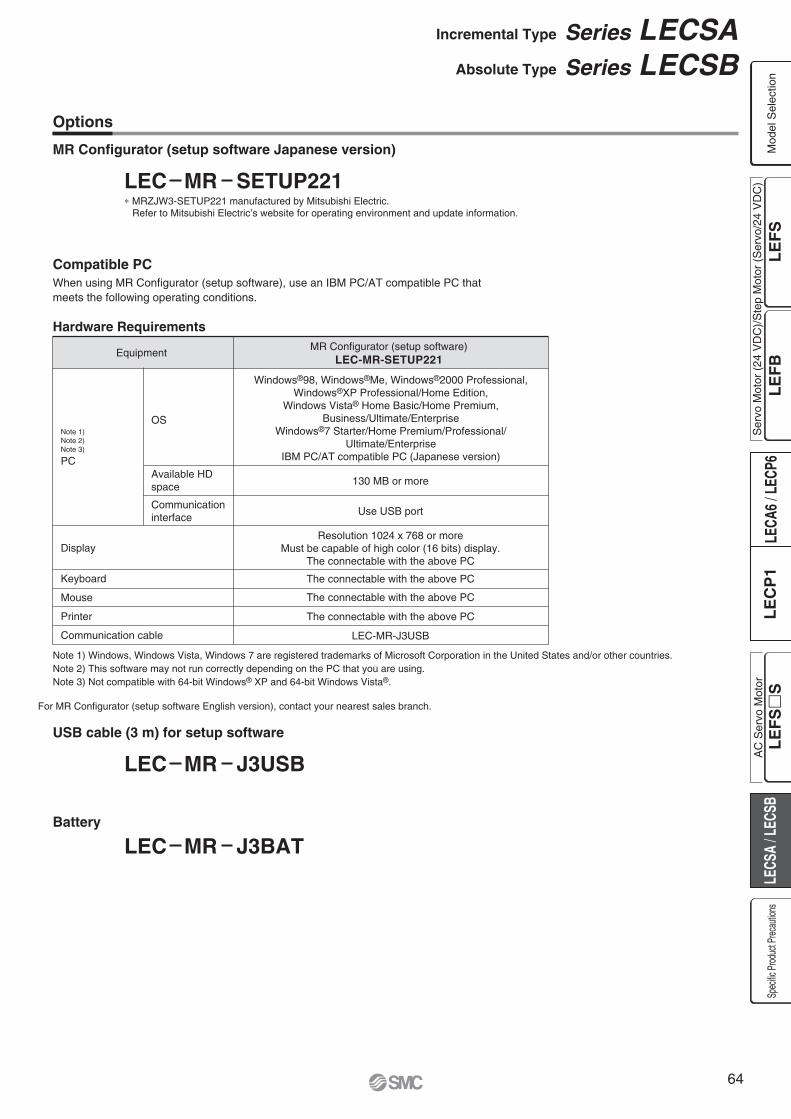
Options
USB cable (3 m) for setup software
Battery
LEC MR J3USB
LEC MR J3BAT
Compatible PC
Hardware Requirements
When using MR Configurator (setup software), use an IBM PC/AT compatible PC that meets the following operating conditions.
Note 1) Windows, Windows Vista, Windows 7 are registered trademarks of Microsoft Corporation in the United States and/or other countries.Note 2) This software may not run correctly depending on the PC that you are using.Note 3) Not compatible with 64-bit Windows® XP and 64-bit Windows Vista®.
Equipment
Note 1)Note 2)Note 3)
PCAvailable HD space
OS
Communication interface
Display
MR Configurator (setup software)LEC-MR-SETUP221
130 MB or more
Windows®98, Windows®Me, Windows®2000 Professional,Windows®XP Professional/Home Edition,
Windows Vista® Home Basic/Home Premium,Business/Ultimate/Enterprise
Windows®7 Starter/Home Premium/Professional/Ultimate/Enterprise
IBM PC/AT compatible PC (Japanese version)
Resolution 1024 x 768 or moreMust be capable of high color (16 bits) display.
The connectable with the above PC
Use USB port
The connectable with the above PC
The connectable with the above PC
The connectable with the above PC
LEC-MR-J3USB
Keyboard
Mouse
Printer
Communication cable
MR Configurator (setup software Japanese version)
LEC MR SETUP221∗ MRZJW3-SETUP221 manufactured by Mitsubishi Electric.
Refer to Mitsubishi Electric’s website for operating environment and update information.
For MR Configurator (setup software English version), contact your nearest sales branch.
Incremental Type Series LECSAAbsolute Type Series LECSB
Ser
vo M
otor
(24
VD
C)/
Ste
p M
otor
(S
ervo
/24
VD
C)
Mod
el S
elec
tion
Spec
ific P
roduc
t Prec
autio
nsA
C S
ervo
Mot
or
64

Series LECSA/LECSBSpecific Product Precautions 1Be sure to read before handling. Refer to back cover for Safety Instructions and the Operation Manual for Electric Actuator Precautions.Please download it via our website. http://www.smcworld.com
Design/Selection
Warning1. Be sure to apply the specified voltage.
Otherwise, malfunction and breakage may be caused. If the applied voltage is lower than the specified, it is possible that the load cannot be moved due to an internal voltage drop of the controller. Please check the operating voltage before use.
2. Do not operate the product beyond the specifications.Otherwise, a fire, malfunction or actuator damage can result. Please check the specifications before use.
3. Install an emergency stop circuit outside of the enclo-sure.Please install an emergency stop outside of the enclosure so that it can stop the system operation immediately and intercept the power supply.
4. In order to prevent damage due to the breakdown and the malfunction of the controller and its peripheral devices, a backup system should be established previously by giving a multiple-layered structure or a fail-safe design to the equipment, etc.
5. If a danger against the personnel is expected due to an abnormal heat generation, smoking, ignition, etc., of the controller and its peripheral devices, cut off the power supply for the product and the system immedi-ately.
Handling
Warning1. Do not touch the inside of the controller and its periph-
eral devices.It may cause an electric shock or damage to the controller.
2. Do not perform the operation or setting of the product with wet hands.It may cause an electric shock.
3. Product with damage or the one lacking of any compo-nents should not be used.It may cause an electric shock, fire, or injury.
4. Use only the specified combination between the electric actuator and controller.It may cause damage to the actuator or the controller.
5. Be careful not to be caught or hit by the workpiece while the actuator is moving.It may cause an injury.
6. Do not connect the power supply or power on the product before confirming the area to which the work-piece moves is safe.The movement of the workpiece may cause an accident.
7. Do not touch the product when it is energized and for some time after power has been disconnected, as it is very hot.It may lead to a burn due to the high temperature.
8. Check the voltage using a tester for more than 5 minutes after power-off in case of installation, wiring and maintenance.It may cause an electric shock, fire, or injury.
Handling
Warning9. Static electricity may cause malfunction or break the
controller. Do not touch the controller while power is supplied.When touching the controller for maintenance, take sufficient measures to eliminate static electricity.
10. Do not use the product in an area where dust, powder dust, water, chemicals or oil is in the air.It will cause failure or malfunction.
11. Do not use the product in an area where a magnetic field is generated.It will cause failure or malfunction.
12. Do not install the product in the environment of flammable gas, explosive gas and corrosive gas.It could lead to fire, explosion and corrosion.
13. Radiant heat from strong heat supplies such as a furnace, direct sunlight, etc., should not be applied to the product.It will cause failure of the controller or its peripheral devices.
14. Do not use the product in an environment subject to a temperature cycle.It will cause failure of the controller or its peripheral devices.
15. Do not use the product in a place where surges are generated.When there are units that generate a large amount of surge around the product (e.g., solenoid type lifters, high frequency induction furnaces, motors, etc.), this may cause deterioration or damage to the product’s internal circuit. Avoid supplies of surge generation and crossed lines.
16. Do not install the product in an environment under the effect of vibrations and impacts.It will cause failure or malfunction.
17. When a surge generating load such as a relay or solenoid valve is directly driven, use a product that incorporates a surge absorption element.
Installation
Warning1. Install the controller and its peripheral devices on a
fire-proof material.A direct installation on or near a flammable material may cause fire.
2. Do not install the product in a place subject to vibra-tions and impacts.It will cause failure or malfunction.
3. The controller should be affixed vertically to a vertical wall.Do not cover the controller's exhaust opening.
4. Install the controller and its peripheral devices on a flat surface.If the mounting surface is distorted or not flat, an unacceptable force may be added to the housing, etc., to cause troubles.
65

Maintenance
Warning1. Perform a maintenance check periodically.
Confirm wiring and screws are not loose.Loose screws or wires may cause unintentional malfunction.
2. Conduct an appropriate functional inspection after completing the maintenance.At times where the equipment or machinery does not operate properly, conduct an emergency stop of the system. Otherwise, an unexpected malfunction may occur and it will become impossible to secure the safety. Conduct a test of the emergency stop in order to confirm the safety of the equipment.
3. Do not disassemble, modify or repair the controller and its peripheral devices.
4. Do not put anything conductive or flammable inside of the controller.It may cause a fire.
5. Do not conduct an insulation resistance test and withstand voltage test on this product.
6. Ensure sufficient space for maintenance activities.Design the system that allows required space for maintenance.
Power Supply
Caution1. Use a power supply that has low noise between lines
and between power and ground.In cases where noise is high, an isolation transformer should be used.
2. To prevent surges from lightning, an appropriate measure should be taken. Ground the surge absorber for lightning separately from the grounding of the controller and its peripheral devices.
Wiring
Warning1. The controller will be damaged if a commercial power
supply (100V/200V) is added to the controller,s servo
motor power (U, V, W). Be sure to check wiring such as wiring mistakes when the power supply is turned on.
2. Connect the ends of the U, V, W wires from the motor cable correctly to the phases (U, V, W) of the servo motor power.If these wires do not match up, it is unable to control the servo motor.
Grounding
Warning1. Be sure to carry out grounding in order to ensure the
noise tolerance.For grounding actuator, connect the copper wire of the actuator to the controller,s protective earth (PE) terminal and connect the copper wire of the controller to the earth via the control panel,s protective earth (PE) terminal. Do not connect them directly to the control panel,s protective earth (PE) terminal.
2. In the unlikely event that malfunction is caused by ground, please disconnect the unit from ground.
Controller
Control panel
PE terminal Actuator
Series LECSA/LECSBSpecific Product Precautions 2Be sure to read before handling. Refer to back cover for Safety Instructions and the Operation Manual for Electric Actuator Precautions.Please download it via our website. http://www.smcworld.com
Ser
vo M
otor
(24
VD
C)/
Ste
p M
otor
(S
ervo
/24
VD
C)
Mod
el S
elec
tion
Spec
ific P
roduc
t Prec
autio
nsA
C S
ervo
Mot
or
66

Lithuania +370 5 2308118 www.smclt.lt [email protected] +31 (0)205318888 www.smcpneumatics.nl [email protected] +47 67129020 www.smc-norge.no [email protected] +48 (0)222119616 www.smc.pl [email protected] +351 226166570 www.smc.eu [email protected] +40 213205111 www.smcromania.ro [email protected] +7 8127185445 www.smc-pneumatik.ru [email protected] +421 (0)413213212 www.smc.sk [email protected] +386 (0)73885412 www.smc.si [email protected] +34 902184100 www.smc.eu [email protected] +46 (0)86031200 www.smc.nu [email protected] +41 (0)523963131 www.smc.ch [email protected] +90 212 489 0 440 www.smcpnomatik.com.tr [email protected] UK +44 (0)845 121 5122 www.smcpneumatics.co.uk [email protected]
Specifications are subject to change without prior notice and any obligation on the part of the manufacturer.SMC CORPORATION Akihabara UDX 15F, 4-14-1, Sotokanda, Chiyoda-ku, Tokyo 101-0021, JAPAN Phone: 03-5207-8249 FAX: 03-5298-5362
1st printing QQ printing QQ 00 Printed in Spain
Austria +43 (0)2262622800 www.smc.at [email protected] +32 (0)33551464 www.smcpneumatics.be [email protected] +359 (0)2807670 www.smc.bg [email protected] Croatia +385 (0)13707288 www.smc.hr [email protected] Republic +420 541424611 www.smc.cz [email protected] Denmark +45 70252900 www.smcdk.com [email protected] Estonia +372 6510370 www.smcpneumatics.ee [email protected] +358 207513513 www.smc.fi [email protected] +33 (0)164761000 www.smc-france.fr [email protected] +49 (0)61034020 www.smc-pneumatik.de [email protected] +30 210 2717265 www.smchellas.gr [email protected] +36 23511390 www.smc.hu [email protected] +353 (0)14039000 www.smcpneumatics.ie [email protected] +39 0292711 www.smcitalia.it [email protected] +371 67817700 www.smclv.lv [email protected]
Safety Instructions Be sure to read “Handling Precautions for SMC Products” (M-E03-3) before using.
SMC Corporation (Europe)
1. The compatibility of the product is the responsibility of the person who designs the equipment or decides its specifications.Since the product specified here is used under various operating conditions, its compatibility with specific equipment must be decided by the person who designs the equipment or decides its specifications based on necessary analysis and test results. The expected performance and safety assurance of the equipment will be the responsibility of the person who has determined its compatibility with the product. This person should also continuously review all specifications of the product referring to its latest catalogue information, with a view to giving due consideration to any possibility of equipment failure when configuring the equipment.
2. Only personnel with appropriate training should operate machinery and equipment.The product specified here may become unsafe if handled incorrectly. The assembly, operation and maintenance of machines or equipment including our products must be performed by an operator who is appropriately trained and experienced.
3. . Do not service or attempt to remove product and machinery/equipment until safety is confirmed.1. The inspection and maintenance of machinery/equipment should only be
performed after measures to prevent falling or runaway of the driven objects have been confirmed.
2. When the product is to be removed, confirm that the safety measures as mentioned above are implemented and the power from any appropriate source is cut, and read and understand the specific product precautions of all relevant products carefully.
3. Before machinery/equipment is restarted, take measures to prevent unexpected operation and malfunction.
4. Contact SMC beforehand and take special consideration of safety measures if the product is to be used in any of the following conditions. 1. Conditions and environments outside of the given specifications, or use
outdoors or in a place exposed to direct sunlight.2. Installation on equipment in conjunction with atomic energy, railways, air
navigation, space, shipping, vehicles, military, medical treatment, combustion and recreation, or equipment in contact with food and beverages, emergency stop circuits, clutch and brake circuits in press applications, safety equipment or other applications unsuitable for the standard specifications described in the product catalogue.
3. An application which could have negative effects on people, property, or animals requiring special safety analysis.
4. Use in an interlock circuit, which requires the provision of double interlock for possible failure by using a mechanical protective function, and periodical checks to confirm proper operation.
Warning
Limited warranty and Disclaimer/Compliance Requirements The product used is subject to the following “Limited warranty and Disclaimer” and “Compliance Requirements”.Read and accept them before using the product.
1. The product is provided for use in manufacturing industries.The product herein described is basically provided for peaceful use in manufacturing industries. If considering using the product in other industries, consult SMC beforehand and exchange specifications or a contract if necessary. If anything is unclear, contact your nearest sales branch.
Caution
Limited warranty and Disclaimer1. The warranty period of the product is 1 year in service or 1.5 years after
the product is delivered.∗2)
Also, the product may have specified durability, running distance or replacement parts. Please consult your nearest sales branch.
2. For any failure or damage reported within the warranty period which is clearly our responsibility, a replacement product or necessary parts will be provided. This limited warranty applies only to our product independently, and not to any other damage incurred due to the failure of the product.
3. Prior to using SMC products, please read and understand the warranty terms and disclaimers noted in the specified catalogue for the particular products.
∗2) Vacuum pads are excluded from this 1 year warranty.A vacuum pad is a consumable part, so it is warranted for a year after it is delivered. Also, even within the warranty period, the wear of a product due to the use of the vacuum pad or failure due to the deterioration of rubber material are not covered by the limited warranty.
Compliance Requirements1. The use of SMC products with production equipment for the manufacture of
weapons of mass destruction (WMD) or any other weapon is strictly prohibited.
2. The exports of SMC products or technology from one country to another are governed by the relevant security laws and regulations of the countries involved in the transaction. Prior to the shipment of a SMC product to another country, assure that all local rules governing that export are known and followed.
These safety instructions are intended to prevent hazardous situations and/or equipment damage. These instructions indicate the level of potential hazard with the labels of “Caution,” “Warning” or “Danger.” They are all important notes for safety and must be followed in addition to International Standards (ISO/IEC)∗1), and other safety regulations.
∗1) ISO 4414: Pneumatic fluid power – General rules relating to systems. ISO 4413: Hydraulic fluid power – General rules relating to systems. IEC 60204-1: Safety of machinery – Electrical equipment of machines. (Part 1: General requirements) ISO 10218-1: Manipulating industrial robots - Safety. etc.
Caution indicates a hazard with a low level of risk which, if not avoided, could result in minor or moderate injury.
Warning indicates a hazard with a medium level of risk which, if not avoided, could result in death or serious injury.
Caution:
Warning:
Danger :Danger indicates a hazard with a high level of risk which, if not avoided, will result in death or serious injury.
Safety Instructions