tc mobile i/o - rs components...
TRANSCRIPT
© PHOENIX CONTACT 2015-05-06105326_en_04
TC MOBILE I/O...
Data sheet
1 Description
The compact TC MOBILE I/O... signaling system allows you
to monitor analog and digital values via the mobile
communication network as well as to remotely switch relay
outputs.
The data is transmitted via SMS, e-mail or GPRS,
depending on the series. The signaling system is available
as a DC or AC version with an expanded voltage range
(10 V ... 60 V DC or 93 V ... 250 V AC). For an overview of
the series, see “Comparison of product features” on page 4.
A USB connection to a computer and a web browser is all
that is needed for configuration. The device features
numerous helpful software functions, such as mobile
communication diagnostics, sending of log books via e-
mail, and different user roles. All product versions can be
mounted on a DIN rail or a mounting surface.
1.1 Applications
– Machine, building, and system monitoring
– Pumps, wastewater treatment plants, water supply
– Lighting control systems, remote switchgear
– Elevators, gates
– Alarm technology and building services
– HVAC technology
– Battery monitoring (up to 60 V)
– Railway applications (in acc. with EN 50121-4)
1.2 Features
– Data transmission via SMS, e-mail, GPRS (ODP
protocol), depending on the product version
– Communication: event-controlled or continual
– Four digital inputs
– Four relay outputs, can be switched via mobile
communication
– DC version: two additional analog inputs, each can be
switched between voltage and current
– Standard SIM card
– Compact design: 4 div. in acc. with DIN 43880
– EX approval: II 3 G Ex nA nC IIC T4 Gc X
– Housing cover, can be sealed
– Configuration via web browser
– SMS alarm in the event of power failure
– Numerous helpful software functions
– Cost-effective remote control substation with OPD
protocol
WARNING: Explosion hazard when used in potentially explosive areas
The device is a category 3 item of electrical equipment. Follow the instructions provided here during installation
and observe the safety notes.
Make sure you always use the latest documentation.
It can be downloaded at phoenixcontact.net/products.
This data sheet is valid for all products listed on the following page:
Remote monitoring via mobile communication
TC MOBILE I/O...
105326_en_04 PHOENIX CONTACT 2 / 19
2 Table of contents
1 Description.................................................................................................................................. 1
2 Table of contents ........................................................................................................................ 2
3 Ordering data.............................................................................................................................. 3
4 Technical Data............................................................................................................................ 5
5 Safety notes................................................................................................................................ 8
6 Description.................................................................................................................................. 9
7 Communication channels at a glance ........................................................................................12
8 Software ................................................................................................................................................................. 14
9 FCC approval.............................................................................................................................18
TC MOBILE I/O...
105326_en_04 PHOENIX CONTACT 3 / 19
3 Ordering data
Operation of the wireless system is only permitted with accessories supplied by Phoenix Contact. The use of other
accessory components may invalidate the operating license. You can find the approved accessories for this
wireless system in this data sheet or listed with the product at phoenixcontact.net/products.
For initial startup, you require a USB cable and an antenna. These accessories are not included in the scope of
delivery.
Remote control and signaling system
Description Type Order No. Pcs.
/ Pkt.
Remote control and signaling system via mobile communication,
four digital inputs and four relay outputs (N/O contact),
two additional analog inputs, each can be switched between current and voltage:
Current: 0 mA ... 20 mA or 4 mA ... 20 mA (switchable),
Voltage: 0 V ... 60 V
Supply voltage of 10 V ... 60 V DC TC MOBILE I/O X200 2903805 1
Supply voltage of 10 V ... 60 V DC, with ODP functionality TC MOBILE I/O X300 2903807 1
Remote control and signaling system via mobile communication,
four digital inputs and four relay outputs (N/O contact),
Supply voltage of 93 V ... 250 V AC TC MOBILE I/O X200 AC 2903806 1
Supply voltage of 93 V ... 250 V DC, with ODP functionality TC MOBILE I/O X300 AC 2903808 1
Accessories
Description Type Order No. Pcs.
/ Pkt.
GSM antenna for direct assembly on the device, angled antenna plug (90°, SMA round plug).
The antenna is suitable for hidden installation in a plastic control cabinet.
PSI-GSM-STUB-ANT 2313342 1
GSM UMTS omnidirectional antenna, 2 dBi gain, 5 m antenna cable with SMA round plug PSI-GSM/UMTS-ANT-OMNI-2-5 2900982 1
GSM UMTS antenna, with omnidirectional characteristic, 2 m antenna cable with SMA round
plug
PSI-GSM/UMTS-QB-ANT 2313371 1
GSM UMTS antenna cable, 10 m long; SMA (male) SMA (female), 50 Ohm impedance PSI-CAB-GSM/UMTS-10M 2900981 1
GSM UMTS antenna cable, 5 m long; SMA (male) SMA (female), 50 Ohm impedance PSI-CAB-GSM/UMTS- 5M 2900980 1
DIN rail power supply, 24 V DC/0.75 A, primary-switched, single phase, 61 mm depth STEP-PS/ 1AC/24DC/0.75 2868635 1
USB cable, 3 meter USB connecting cable, USB plug type A to USB plug type mini-B;
length: 3 m
CABLE-USB/MINI-USB-3.0M 2986135 1
ODP licenses
Description Type Order No. Pcs.
/ Pkt.
ODP licenses for TC MOBILE I/O X300 and X300 AC
Software dongle AX ODP SERVER for 5 remote control substations AX ODP SERVER 5FU 2700391
Software dongle AX ODP SERVER for 8 remote control substations AX ODP SERVER 8FU 2700392
Software dongle AX ODP SERVER for 10 remote control substations AX ODP SERVER 10FU 2700393
Software dongle AX ODP SERVER for 15 remote control substations AX ODP SERVER 15FU 2700394
Software dongle AX ODP SERVER for 20 remote control substations AX ODP SERVER 20FU 2700396
Software dongle AX ODP SERVER for 25 remote control substations AX ODP SERVER 25FU 2700397
Software dongle AX ODP SERVER for 30 remote control substations AX ODP SERVER 30FU 2700399
Software dongle AX ODP SERVER for 50 remote control substations AX ODP SERVER 50FU 2700400
Software dongle AX ODP SERVER for 75 remote control substations AX ODP SERVER 75FU 2700401
Software dongle AX ODP SERVER for 100 remote control substations AX ODP SERVER 100FU 2700402
Software dongle AX ODP SERVER for 150 remote control substations AX ODP SERVER 150FU 2700403
Software dongle AX ODP SERVER for 200 remote control substations AX ODP SERVER 200FU 2700404
Software dongle AX ODP SERVER for 250 remote control substations AX ODP SERVER 250FU 2700406
Further ODP licensing models on request

TC MOBILE I/O...
105326_en_04 PHOENIX CONTACT 4 / 19
Comparison of product features
Supply voltage X200 X200 AC X300 X300 AC
Supply voltage 10 V ... 60 V DC ● ●
Supply voltage 93 V ... 250 V AC ● ●
Inputs X200 X200 AC X300 X300 AC
Four digital inputs ● ● ● ●
Two analog inputs, can be switched between current and voltage ● ●
Continual data transmission via SMS, e-mail ● ●
Event-controlled data transmission via SMS, e-mail ● ●
Continual data transmission via ODP (GPRS) ● ●
Event-controlled data transmission via ODP (GPRS) ● ●
Outputs X200 X200 AC X300 X300 AC
Four relay outputs (N/O contact) ● ● ● ●
Set a switching output for incoming SMS ● ●
Set a switching output for incoming ODP command ● ●
Set a switching output for incoming e-mail (This function is not enabled
for security reasons)
Communication channels X200 X200 AC X300 X300 AC
Sending and receiving SMS messages ● ●
Sending e-mails on the Internet ● ●
Bidirectional communication with an ODP control system (GPRS) ● ●
Security X200 X200 AC X300 X300 AC
Password protection (login on the device website) ● ● ● ●
Encrypted memory for the SIM card PIN ● ● ● ●
Selection of authorized users (white list) ● ● ● ●
Configuration changes are logged in the log book ● ● ● ●
Three user groups: admin, user, user-defined ● ● ● ●
Data encryption according to ODP specification ● ●
Acknowledgement of receipt of incoming SMS messages ● ●
Alarms and signaling X200 X200 AC X300 X300 AC
Via SMS in the event of a power failure ● ●
Event-controlled, for positive and/or negative edge ● ● ● ●
Analog inputs: have four switching thresholds for alarms (hysteresis),
upper value range (fallen below/exceeded) and lower value range (fallen below/exceeded)
● ●
Alarm for current input (configuration: 4 mA ... 20 mA) as soon as current is < 4 mA ● ●
Send to individuals and groups of people (SMS and e-mail) ● ●
Alarm to an ODP control system ● ●
Data transmission X200 X200 AC X300 X300 AC
Cyclical, at a regular point in time (minute to month), via SMS or e-mail ● ●
Cyclical, at a regular point in time (minute to month), via ODP ● ●
Address book entries X200 X200 AC X300 X300 AC
Address book with up to 50 contacts ● ●
Change address book entries via SMS,
modification via e-mail is not supported for security reasons
● ●
ODP partner ● ●
Configuration X200 X200 AC X300 X300 AC
Integrated configuration software via web browser (USB interface) ● ● ● ●
Supported languages: English, German ● ● ● ●
Device configuration can be exported or imported as a file ● ● ● ●

TC MOBILE I/O...
105326_en_04 PHOENIX CONTACT 5 / 19
4 Technical Data
Diagnostics X200 X200 AC X300 X300 AC
Integrated log book ● ● ● ●
Mobile communication network diagnostics ● ● ● ●
Charge request ● ●
SMS counter ● ●
Send log book entries as e-mail ● ●
Data volume counter (net data volume) ● ● ● ●
Additional functions X200 X200 AC X300 X300 AC
Integrated clock, incl. 96 h buffer at 25°C, minimum 48 h ● ● ● ●
Time stamp from the ODP control system ● ●
General data
Housing system 4 div. in acc. with DIN 43880
Dimensions 71.6 mm x 62.2 mm x 89.7 mm
Degree of protection IP20
Ambient temperature
Storage
Operation
-40°C … +85°C
-25°C … +70°C (observe derating)
Derating, maximum ambient temperature
Relay not used
Maximum relay load current 1 A
Maximum relay load current 5 A (AC version)
Maximum relay load current 6 A (DC version)
SMS mode
70°C
60°C
50°C
50°C
GPRS data link
60°C
55°C
50°C
50°C
Relative humidity 0 % ... 95 %
Permitted characters for configuration
SMS text messages
Input fields for credentials
Further text input fields (e.g. commands sent to the device by SMS)
NetBios name
Command for credit check
@£$¥èéùìòÇ\nØø\rÅå_ÆæßÉ !\"#€%&'()*+,-.\/0-9:;<=>\?¡A-ZÄÖÑܧ¿a-
zäöñüà
!\"#$%&'()*+,-.\/0-9:;<=>\?@A-Z\[\/\]^_`a-z{|}~
@£$¥èéùìòÇ\nØø\rÅå_ÆæßÉ !\"#€%&'()*+,-.\/0-9:;<=>\?¡A-ZÄÖÑܧ¿a-
zäöñüà
0-9a-zA-Z_\-
0-9a-zA-Z_\-
Comparison of product features
Power supply1
DC version
Supply voltage 10 V DC … 60 V DC
Current consumption Approx. 105 mA ... 175 mA at 24 V DC
Standby (without engine) 35 mA ... 65 mA at 24 V DC
AC version
Supply voltage 93 V AC … 250 V AC
Frequency 47.5 Hz … 63 Hz
Frequency tolerance -15% … +10% (with regard to 50 Hz and 60 Hz)
Current consumption 30 mA ... 55 mA at 230 V AC, typical
Standby (without engine) 10 mA ... 15 mA at 230 V AC
1Supply only via the USB interface is possible with limited functionality.

TC MOBILE I/O...
105326_en_04 PHOENIX CONTACT 6 / 19
Inputs
Digital inputs
Number 4
Designation DI1, DI2, DI3, DI4
Electric strength Maximum supply voltage
Discrimination threshold, DC version Low = 0 % ... 30 % of the applied supply voltage
High = 70 % ... 100 % of the applied supply voltage
Discrimination threshold, AC version Low = 0 V ... 50 V AC
High = 90 V ... 250 V AC
Typical input current at 250 V AC: 3.5 mA
Analog inputs (DC version only)
Number 2, each with 3 terminal blocks (U, I, GND)
Designation U1, I1, GND1
U2, I2, GND2
Electric strength Maximum supply voltage
Voltage range (U1 and U2) 0 V ... 60 V
Current range (I1 and I2) 0 mA ... 20 mA/4 mA ... 20 mA (offset switching via software)
Electric strength of current input Maximum supply voltage
Resolution 15-bit
Error limit, with reference to the input range
Current input accuracy
Voltage input accuracy
Error limit with interference
±0.1 %
±0.1 %
±0.2 %
Input impedance: voltage input 600 kOhm
Input impedance: current input 50 Ohm
Sample speed < 200 ms
Tolerance through temperature response < ±0.2 %
Switching outputs
DC version
Technical data for the relay
Number 4
Contact type 1
Limiting continuous current 6 A
Maximum switching voltage 60 V DC
Maximum switching capacity 1500 VA
Minimum switching voltage 5 V
Minimum switching current > 10 mA
Insulation distance Between coil and contact 4000 Vrms
DC load limit curve
Switching current [A]
Switching voltage [V]
Ohmic load
AC version
Technical data for the relay
Number 4
Contact type 1
[A]
[V]
0,110
20
30
40
50
60
0,3 0,5 1 2 5 10 20
TC MOBILE I/O...
105326_en_04 PHOENIX CONTACT 7 / 19
Limiting continuous current 5 A
Maximum switching voltage 250 V AC/125 V DC
Maximum switching capacity 750 VA
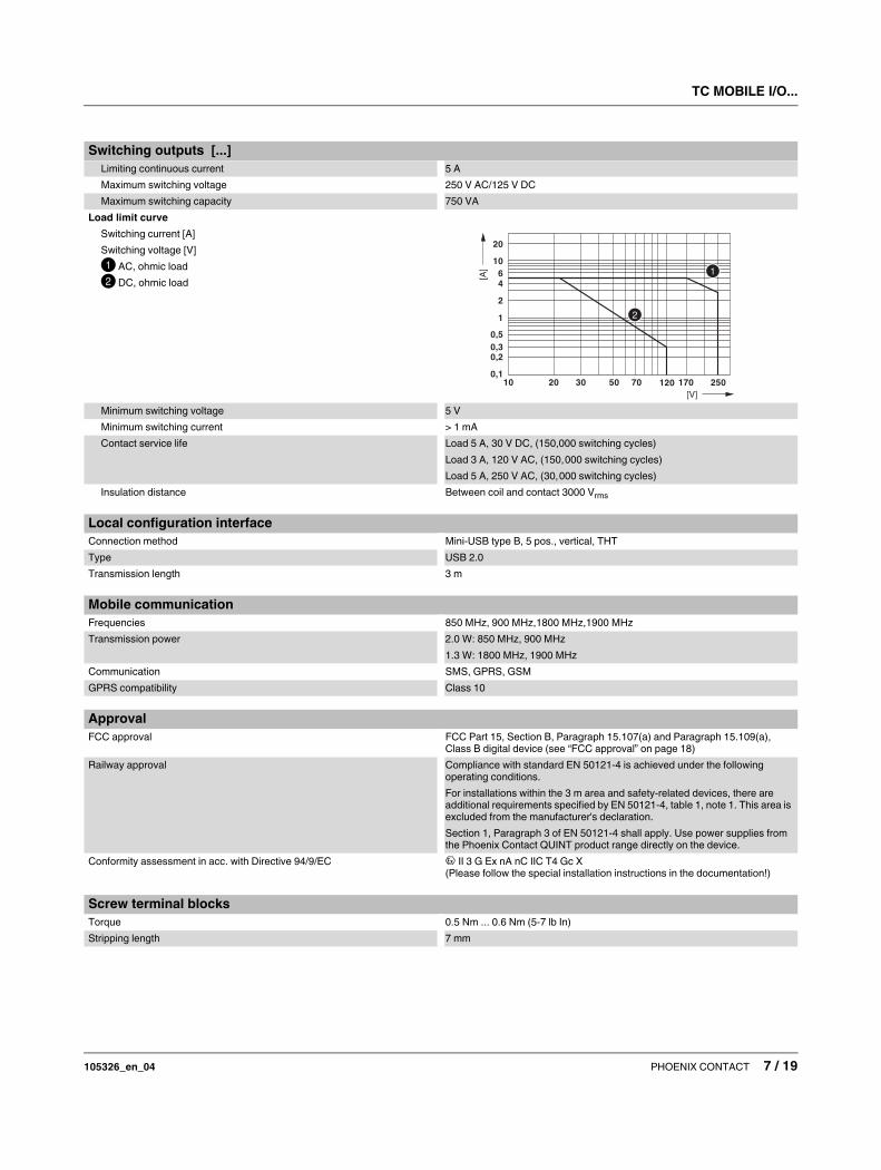
Load limit curve
Switching current [A]
Switching voltage [V]
AC, ohmic load
DC, ohmic load
Minimum switching voltage 5 V
Minimum switching current > 1 mA
Contact service life Load 5 A, 30 V DC, (150,000 switching cycles)
Load 3 A, 120 V AC, (150,000 switching cycles)
Load 5 A, 250 V AC, (30,000 switching cycles)
Insulation distance Between coil and contact 3000 Vrms
Switching outputs [...]
0,1
0,20,3
0,5
1
2
46
10
20
10 20 30 50 70 120 250
[V]
[A]
170
Local configuration interface
Connection method Mini-USB type B, 5 pos., vertical, THT
Type USB 2.0
Transmission length 3 m
Mobile communication
Frequencies 850 MHz, 900 MHz,1800 MHz,1900 MHz
Transmission power 2.0 W: 850 MHz, 900 MHz
1.3 W: 1800 MHz, 1900 MHz
Communication SMS, GPRS, GSM
GPRS compatibility Class 10
Approval
FCC approval FCC Part 15, Section B, Paragraph 15.107(a) and Paragraph 15.109(a),
Class B digital device (see “FCC approval” on page 18)
Railway approval Compliance with standard EN 50121-4 is achieved under the following
operating conditions.
For installations within the 3 m area and safety-related devices, there are
additional requirements specified by EN 50121-4, table 1, note 1. This area is
excluded from the manufacturer's declaration.
Section 1, Paragraph 3 of EN 50121-4 shall apply. Use power supplies from
the Phoenix Contact QUINT product range directly on the device.
Conformity assessment in acc. with Directive 94/9/EC X II 3 G Ex nA nC IIC T4 Gc X
(Please follow the special installation instructions in the documentation!)
Screw terminal blocks
Torque 0.5 Nm ... 0.6 Nm (5-7 lb In)
Stripping length 7 mm
TC MOBILE I/O...
105326_en_04 PHOENIX CONTACT 8 / 19
5 Safety notes
Only for the DC devices TC MOBILE I/O X200 and
TC MOBILE I/O X300:
Only for the AC devices TC MOBILE I/O X200 AC and
TC MOBILE I/O X300 AC:
5.1 Installation notes
• The category 3 device is designed for installation in
zone 2 potentially explosive areas. It meets the
requirements of EN 60079-0:2012 and EN 60079-
15:2010.
• Installation, operation, and maintenance may only be
carried out by qualified electricians. Follow the
installation instructions as described. When installing
and operating the device, the applicable regulations
and safety directives (including national safety
directives) as well as generally recognized technical
regulations must be observed. The safety data is
provided in the package slip and on the certificates
(conformity assessment, additional approvals where
applicable).
• Do not open or modify the device. Do not repair the
device yourself; replace it with an equivalent device
instead. Repairs may only be carried out by the
manufacturer. The manufacturer is not liable for harm
resulting from noncompliance.
• The IP20 degree of protection (IEC 60529/EN 60529) of
the device is intended for use in a clean and dry
environment. Do not subject the device to mechanical
and/or thermal loads that exceed the specified limits.
• The device is not suitable for installation in zone 22.
• If, however, you wish to use the device in zone 22, it
must be installed in housing that complies with
IEC/EN 60079-31. For this purpose, observe the
maximum surface temperatures. Observe the
requirements of IEC/EN 60079-14.
• Operation of the wireless system is only permitted with
the use of accessories supplied by Phoenix Contact.
The use of other accessory components may invalidate
the operating license. You can find the approved
accessories for this wireless system listed with the
product at phoenixcontact.net/products.
WARNING: Risk of electric shock
During operation, certain parts of this device may
carry hazardous voltages. Disregarding this
warning may result in property damage and/or
serious personal injury.
– Provide overcurrent protection (I ≤ 6 A)
within the installation.
– The power output of the power supply unit
must not exceed 240 VA.
WARNING: Risk of electric shock
During operation, certain parts of this device may
carry hazardous voltages. Disregarding this
warning may result in property damage and/or
serious personal injury.
– Never carry out work on live parts.
– This device is not suitable for monitoring
sensitive systems or time-critical processes.
GSM network failures or power supply
interruptions may adversely affect
monitoring.
– The device is intended for installation in a
control cabinet or a comparable container.
The device may only be operated when it has
been installed. The control cabinet must
meet the requirements of EN/IEC 60950-1 in
terms of fire protection shielding.
Additionally, it must provide adequate
protection against electric shock (protection
against contact).
– It must be possible to disconnect the device
from the power supply. Install an appropriate
disconnecting device (fuse, miniature circuit
breaker, etc.) for this purpose.
– During electrical installation, observe the
current standards and regulations.
Installation must be carried out by an expert.
WARNING:
Make sure that the following notes and
instructions are observed and complied with.
TC MOBILE I/O...
105326_en_04 PHOENIX CONTACT 9 / 19
5.2 Installation in zone 2
• Observe the specified conditions for use in potentially
explosive areas!
• Install the device in a suitable, approved housing (with
at least IP54 protection) that meets the requirements of
EN 60079-15. For this purpose, observe the
requirements of IEC 60079-14 / EN 60079-14.
• Only devices that are suitable for operation in Ex zone 2
and for the conditions at the installation location may be
connected to the supply and signal circuits in zone 2.
• In potentially explosive areas, snap the device on or off
the DIN rail connector, and connect or disconnect the
cables only when the power is disconnected.
• The switches of the device that can be accessed may
only be actuated when the power supply to the device
is disconnected.
• The mini-USB configuration interface may only be used
if it has been ensured that there is no potentially
explosive atmosphere present.
• The device must be stopped and immediately removed
from the hazardous area if it is damaged, was subjected
to an impermissible load, stored incorrectly, or if it
malfunctions.
• Ensure that the emitted radio frequency energy is
neither bundled (focused) by the antenna itself nor by
any installations in the environment of the antenna, and
that it cannot enter neighboring zones 1 or 0. Please
refer to the technical data for the HF output power. It
must not exceed 2 W.
• The HF cable to the antenna must be suitable for the
ambient conditions. Install the cable so that it is
protected against mechanical damage, corrosion,
chemical stress, and negative effects from heat or UV
radiation. The same applies to the antenna which is
connected to the cable and which functions as a cable
termination.
• The antenna itself must meet the relevant requirements
of EN 60079-0.
6 Description
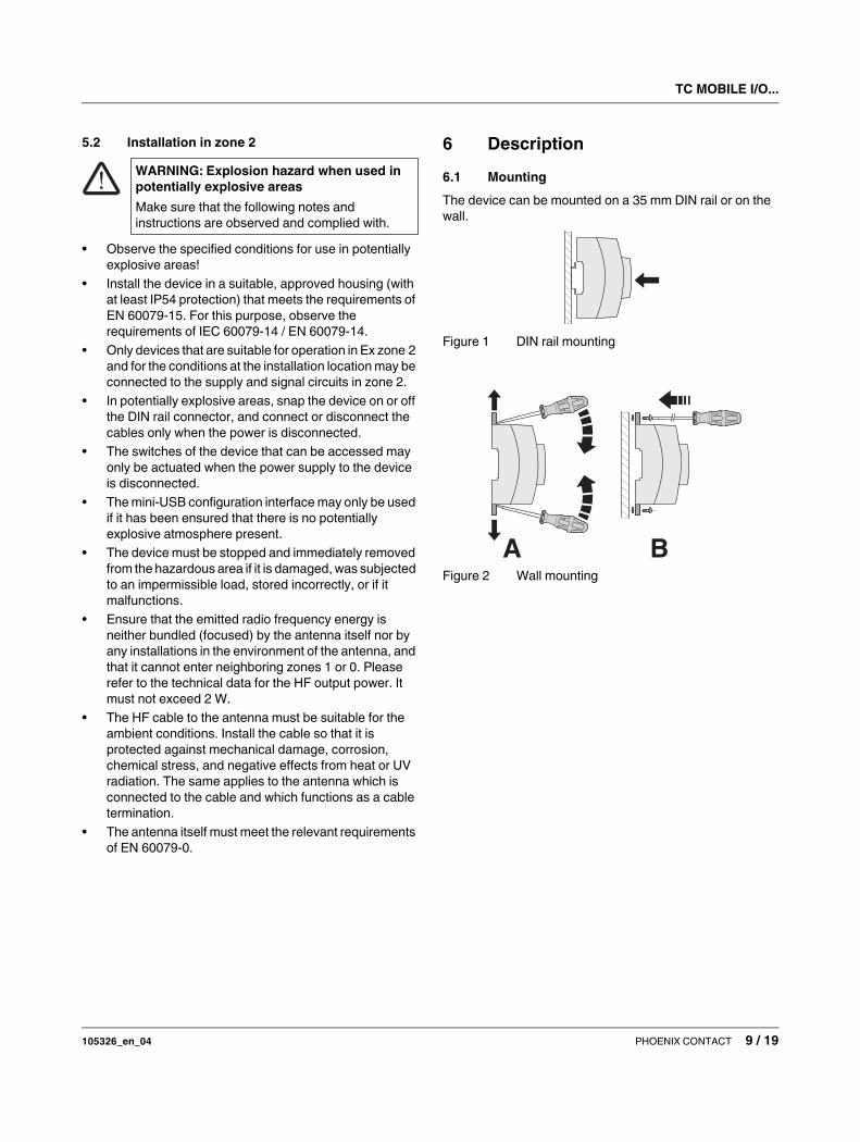
6.1 Mounting
The device can be mounted on a 35 mm DIN rail or on the
wall.
Figure 1 DIN rail mounting
Figure 2 Wall mounting
WARNING: Explosion hazard when used in
potentially explosive areas
Make sure that the following notes and
instructions are observed and complied with.
A B
TC MOBILE I/O...
105326_en_04 PHOENIX CONTACT 10 / 19
6.2 TC MOBILE I/O X200 and TC MOBILE I/O X300
TC
MO
BIL
E
SIM
Network
Device
Reset
USB SIM
1 2 3 4
Digital IN
Relay OUT
DocumentationTC MOBILE I/O
X200
Ord.-No.:2903806
DI1 DI2 DI3 DI4 +-
U1 I1 U2 I21 2 O1 UB1 O2 O1 UB1 O2
12
3
4
5
6
7
8
9
10 11 12 13
15
1617
14
0,5-0,6 Nm5-7 lb In
O1 UB1 O2
L
N
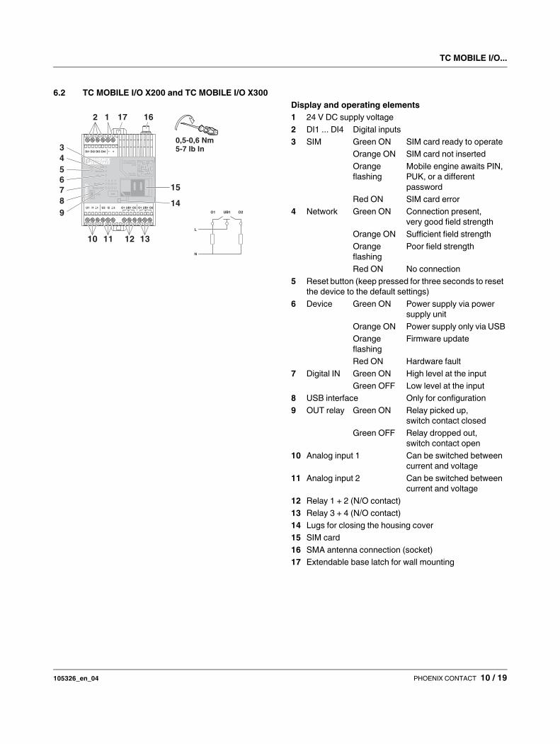
Display and operating elements
1 24 V DC supply voltage
2 DI1 ... DI4 Digital inputs
3 SIM Green ON SIM card ready to operate
Orange ON SIM card not inserted
Orange
flashing
Mobile engine awaits PIN,
PUK, or a different
password
Red ON SIM card error
4 Network Green ON Connection present,
very good field strength
Orange ON Sufficient field strength
Orange
flashing
Poor field strength
Red ON No connection
5 Reset button (keep pressed for three seconds to reset
the device to the default settings)
6 Device Green ON Power supply via power
supply unit
Orange ON Power supply only via USB
Orange
flashing
Firmware update
Red ON Hardware fault
7 Digital IN Green ON High level at the input
Green OFF Low level at the input
8 USB interface Only for configuration
9 OUT relay Green ON Relay picked up,
switch contact closed
Green OFF Relay dropped out,
switch contact open
10 Analog input 1 Can be switched between
current and voltage
11 Analog input 2 Can be switched between
current and voltage
12 Relay 1 + 2 (N/O contact)
13 Relay 3 + 4 (N/O contact)
14 Lugs for closing the housing cover
15 SIM card
16 SMA antenna connection (socket)
17 Extendable base latch for wall mounting
TC MOBILE I/O...
105326_en_04 PHOENIX CONTACT 11 / 19
6.3 TC MOBILE I/O X200 AC and
TC MOBILE I/O X300 AC
0,5-0,6 Nm5-7 lb In
TC
MO
BIL
E
SIM
Network
Device
Reset
USB SIM
1 2 3 4
Digital IN
Relay OUT
DocumentationTC MOBILE I/O
X200
Ord.-No.:2903806
N L
ND ND DI1 DI2 DI3 DI4 O1 UB1 O2 O1 UB1 O2
12
3
4
5
6
7
8
9
10 11 12 13
15
14
1617
O1 UB1 O2
L
N
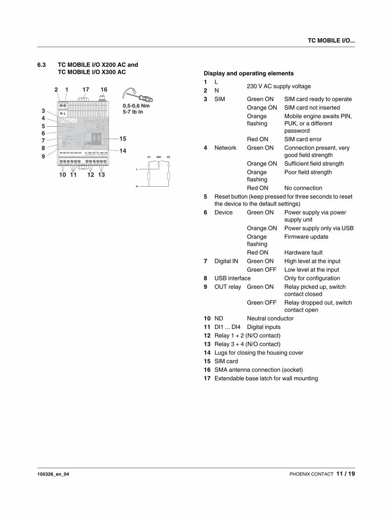
Display and operating elements
1 L230 V AC supply voltage
2 N
3 SIM Green ON SIM card ready to operate
Orange ON SIM card not inserted
Orange
flashing
Mobile engine awaits PIN,
PUK, or a different
password
Red ON SIM card error
4 Network Green ON Connection present, very
good field strength
Orange ON Sufficient field strength
Orange
flashing
Poor field strength
Red ON No connection
5 Reset button (keep pressed for three seconds to reset
the device to the default settings)
6 Device Green ON Power supply via power
supply unit
Orange ON Power supply only via USB
Orange
flashing
Firmware update
Red ON Hardware fault
7 Digital IN Green ON High level at the input
Green OFF Low level at the input
8 USB interface Only for configuration
9 OUT relay Green ON Relay picked up, switch
contact closed
Green OFF Relay dropped out, switch
contact open
10 ND Neutral conductor
11 DI1 ... DI4 Digital inputs
12 Relay 1 + 2 (N/O contact)
13 Relay 3 + 4 (N/O contact)
14 Lugs for closing the housing cover
15 SIM card
16 SMA antenna connection (socket)
17 Extendable base latch for wall mounting

TC MOBILE I/O...
105326_en_04 PHOENIX CONTACT 12 / 19
7 Communication channels at a
glance
7.1 Overview
The signaling system enables communication via various
channels.
However, for security reasons, the following channels are
not supported.
If you wish to use the receiving e-mail, alarm call, or
switching via call functions despite the increased security
risk, please get in touch with Phoenix Contact.
7.2 Sending e-mail (X200 and X200 AC)
The X200 and X200 AC signaling systems can also send
alarms and cyclical messages by e-mail. For this purpose,
GPRS communication is established with an e-mail server.
It is possible to send the entire log book as an e-mail.
In the event of a power failure, e-mails can no longer be sent
because it requires more power to establish the connection
to an e-mail server than the internal capacitor can store.
However, it is still possible to send an SMS.
E-mail communication can take place without encryption or
with SSL encryption. STARTTLS is not supported at
present. Please consult your e-mail service provider
beforehand. Most e-mail service providers support SSL
encryption.
Figure 3 Sending e-mails
7.3 Sending SMS (X200 and X200 AC)
Sending an SMS has the advantage of enabling
communication even if mobile communication reception is
very poor. An SMS can also be sent without an Internet
connection. The X200 and X200 AC signaling systems can
send an SMS to individual devices or to a device group. The
device group can be configured as a signal chain.
7.4 Receiving SMS (X200 and X200 AC)
You can switch the integrated relays via SMS messages. If
required all four relays can even be switched with a single
SMS. It is also possible to send the log book to an e-mail
address.
In addition, single telephone book entries can be
exchanged via SMS (name and phone number).
7.5 Receiving e-mail (X200 and X200 AC)
For security reasons, the signaling system does not process
any incoming e-mails.
Furthermore, many e-mail servers limit the amount of times
that a mailbox can be opened per day. In order for the
signaling system to be able to promptly respond to incoming
e-mails, it must regularly read the mailbox from the server at
very short time intervals. This is prevented by many e-mail
services.
Communication via SMS or ODP is a suitable alternative.
Sending e-mail (X200 and X200 AC, optionally with
SSL encryption)
Sending SMS (X200 and X200 AC)
Receiving SMS (X200 and X200 AC)
Communication with an ODP server (X300 and
X300 AC)
Alarm via call (free flash call)
Switching via call
Receiving e-mails from the Internet
GPRS communication between two mobile
communication devices
In the event of a power failure, an SMS can still be
sent to a selected device.
The signaling systems are preset so that only
SMS commands from contacts that are entered in
the telephone book can be processed (white list).
This function can be deactivated.
TC MOBILE I/O...
105326_en_04 PHOENIX CONTACT 13 / 19
7.6 GPRS communication between two mobile
communication devices
Many mobile communication providers prevent direct
GPRS communication between mobile communication
devices that use standard SIM cards. This special function
is not supported because it is heavily dependent on the
mobile communication network operator.
Communication via SMS or ODP is a suitable alternative.
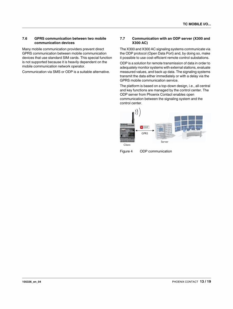
7.7 Communication with an ODP server (X300 and
X300 AC)
The X300 and X300 AC signaling systems communicate via
the ODP protocol (Open Data Port) and, by doing so, make
it possible to use cost-efficient remote control substations.
ODP is a solution for remote transmission of data in order to
adequately monitor systems with external stations, evaluate
measured values, and back up data. The signaling systems
transmit the data either immediately or with a delay via the
GPRS mobile communication service.
The platform is based on a top-down design, i.e., all central
and key functions are managed by the control center. The
ODP server from Phoenix Contact enables open
communication between the signaling system and the
control center.
Figure 4 ODP communication
GPRS
ServerClient
TC MOBILE I/O...
105326_en_04 PHOENIX CONTACT 14 / 19
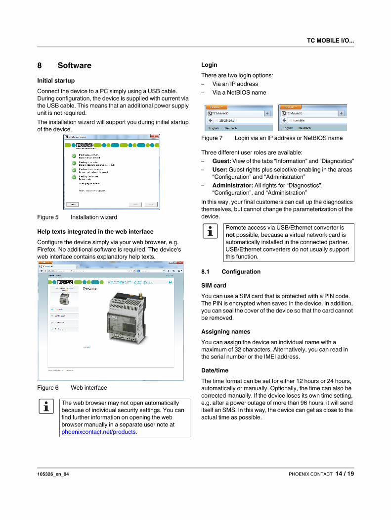
8 Software
Initial startup
Connect the device to a PC simply using a USB cable.
During configuration, the device is supplied with current via
the USB cable. This means that an additional power supply
unit is not required.
The installation wizard will support you during initial startup
of the device.
Figure 5 Installation wizard
Help texts integrated in the web interface
Configure the device simply via your web browser, e.g.
Firefox. No additional software is required. The device's
web interface contains explanatory help texts.
Figure 6 Web interface
Login
There are two login options:
– Via an IP address
– Via a NetBIOS name
Figure 7 Login via an IP address or NetBIOS name
Three different user roles are available:
– Guest: View of the tabs “Information” and “Diagnostics”
– User: Guest rights plus selective enabling in the areas
“Configuration” and “Administration”
– Administrator: All rights for “Diagnostics”,
“Configuration”, and “Administration”
In this way, your final customers can call up the diagnostics
themselves, but cannot change the parameterization of the
device.
8.1 Configuration
SIM card
You can use a SIM card that is protected with a PIN code.
The PIN is encrypted when saved in the device. In addition,
you can seal the cover of the device so that the card cannot
be removed.
Assigning names
You can assign the device an individual name with a
maximum of 32 characters. Alternatively, you can read in
the serial number or the IMEI address.
Date/time
The time format can be set for either 12 hours or 24 hours,
automatically or manually. Optionally, the time can also be
corrected manually. If the device loses its own time setting,
e.g. after a power outage of more than 96 hours, it will send
itself an SMS. In this way, the device can get as close to the
actual time as possible.
The web browser may not open automatically
because of individual security settings. You can
find further information on opening the web
browser manually in a separate user note at
phoenixcontact.net/products.
Remote access via USB/Ethernet converter is
not possible, because a virtual network card is
automatically installed in the connected partner.
USB/Ethernet converters do not usually support
this function.
TC MOBILE I/O...
105326_en_04 PHOENIX CONTACT 15 / 19
Telephone book
The telephone book contains up to 50 contacts with name,
phone number, or e-mail address. You can also change
telephone book entries via SMS. When the entry has been
successfully changed, the administrator receives
confirmation by SMS.
Signal chain
You can create a signal chain. An alarm is sent to the signal
chain’s devices by e-mail or SMS according to the
chronological order of telephone entries. E-mail recipients
cannot confirm the message however.
The signal chain is interrupted when the device receives a
confirmation SMS. You are free to choose the text of the
confirmation SMS. The time window within which the
devices have to send confirmation can be set to between
one minute and 999 hours.
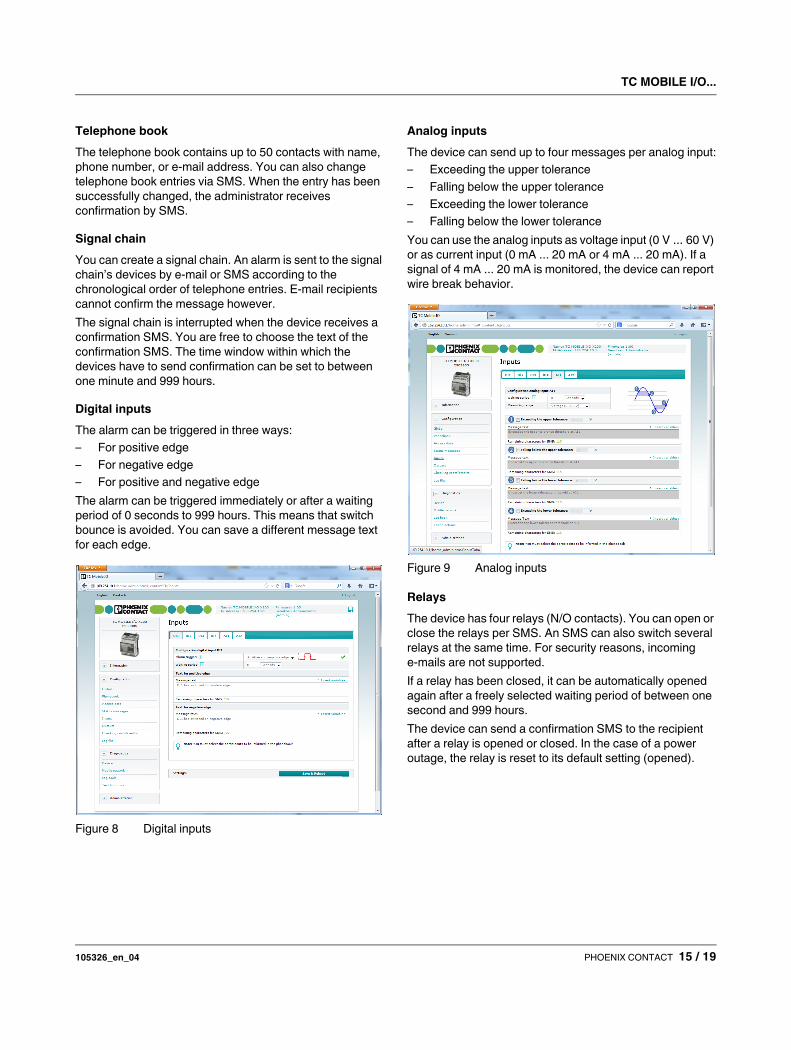
Digital inputs
The alarm can be triggered in three ways:
– For positive edge
– For negative edge
– For positive and negative edge
The alarm can be triggered immediately or after a waiting
period of 0 seconds to 999 hours. This means that switch
bounce is avoided. You can save a different message text
for each edge.
Figure 8 Digital inputs
Analog inputs
The device can send up to four messages per analog input:
– Exceeding the upper tolerance
– Falling below the upper tolerance
– Exceeding the lower tolerance
– Falling below the lower tolerance
You can use the analog inputs as voltage input (0 V ... 60 V)
or as current input (0 mA ... 20 mA or 4 mA ... 20 mA). If a
signal of 4 mA ... 20 mA is monitored, the device can report
wire break behavior.
Figure 9 Analog inputs
Relays
The device has four relays (N/O contacts). You can open or
close the relays per SMS. An SMS can also switch several
relays at the same time. For security reasons, incoming
e-mails are not supported.
If a relay has been closed, it can be automatically opened
again after a freely selected waiting period of between one
second and 999 hours.
The device can send a confirmation SMS to the recipient
after a relay is opened or closed. In the case of a power
outage, the relay is reset to its default setting (opened).
TC MOBILE I/O...
105326_en_04 PHOENIX CONTACT 16 / 19
8.2 Messages
Alarm messages
The device sends alarm messages as SMS or e-mail.
E-mails are sent to an SMTP server. The e-mails can be
sent without encryption or with SSL encryption.
You are free to choose the text of the alarm message, and
to add variables as well.
Example:
“... The input DI1 has the state: #DI1#...”
(#DI1# = Variable)
The firmware 1.0 supports the following variables:
– Device name
– Serial number of the device
– IMEI number of the device
– Time stamp of the current time
– Status of all four digital inputs (high = 1, low = 0)
– Status of the individual digital inputs (1 ... 4)
– Status of the individual analog inputs (1 ... 2)
– Status of all four relay outputs
– Status of the individual relay outputs (1 ... 4)
– Number of sent SMS messages
– Data volumes currently used
– Current network operator
Periodic status messages
In addition to alarm messages, the device can also send
periodic status messages. The time interval can be between
five minutes and one month.
Status message for power outage
The device can send a freely configurable SMS to a
telephone book device when switched off, during a power
outage, or when being started. The SMS is sent to the
selected device once. It is not possible to send an e-mail
because the power consumption is too high.
Status requests via SMS
You can request the current status of the inputs and outputs
via SMS.
8.3 Diagnostics
You can see all the relevant diagnostics information in the
“Device status” and “Mobile communication” areas. In this
way, you can quickly check the function of the device.
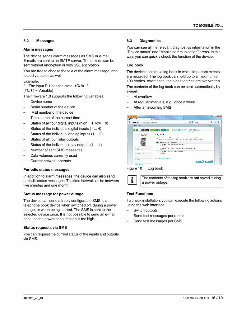
Log book
The device contains a log book in which important events
are recorded. The log book can hold up to a maximum of
100 entries. After these, the oldest entries are overwritten.
The contents of the log book can be sent automatically by
e-mail:
– At overflow
– At regular intervals, e.g., once a week
– After an incoming SMS
Figure 10 Log book
Test Functions
To check installation, you can execute the following actions
using the web interface:
– Switch outputs
– Send test messages per e-mail
– Send test messages per SMS
The contents of the log book are not saved during
a power outage.
TC MOBILE I/O...
105326_en_04 PHOENIX CONTACT 17 / 19
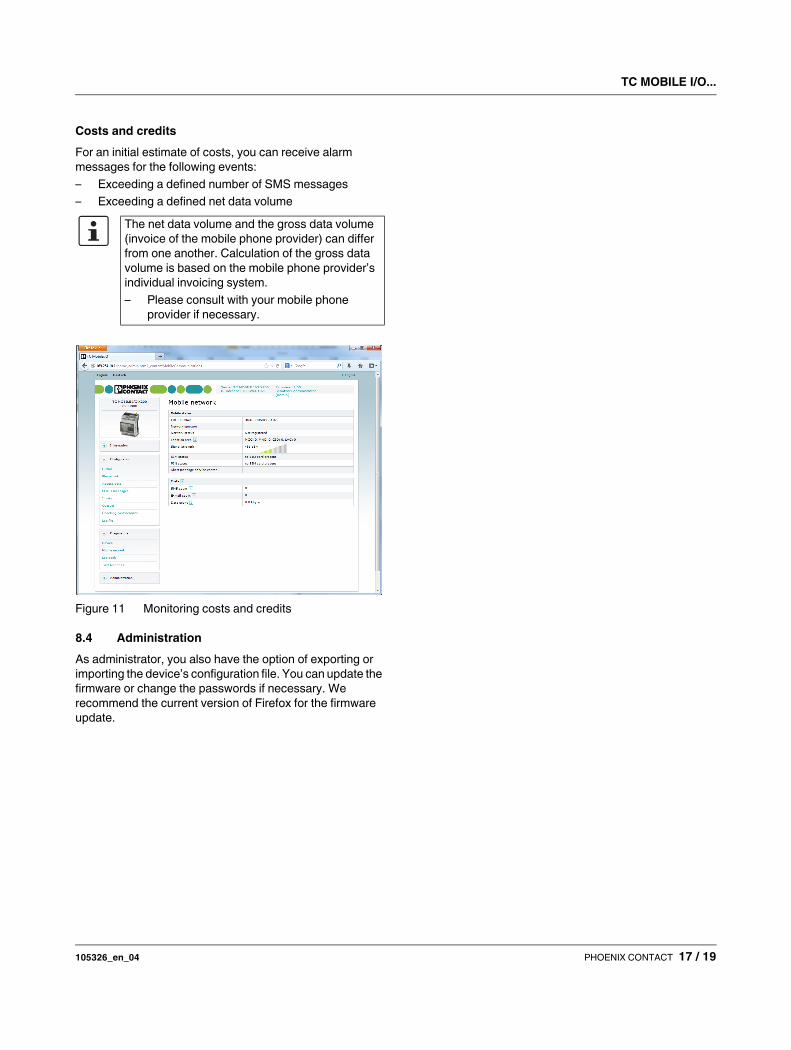
Costs and credits
For an initial estimate of costs, you can receive alarm
messages for the following events:
– Exceeding a defined number of SMS messages
– Exceeding a defined net data volume
Figure 11 Monitoring costs and credits
8.4 Administration
As administrator, you also have the option of exporting or
importing the device’s configuration file. You can update the
firmware or change the passwords if necessary. We
recommend the current version of Firefox for the firmware
update.
The net data volume and the gross data volume
(invoice of the mobile phone provider) can differ
from one another. Calculation of the gross data
volume is based on the mobile phone provider’s
individual invoicing system.
– Please consult with your mobile phone
provider if necessary.
TC MOBILE I/O...
105326_en_04 PHOENIX CONTACT 18 / 19
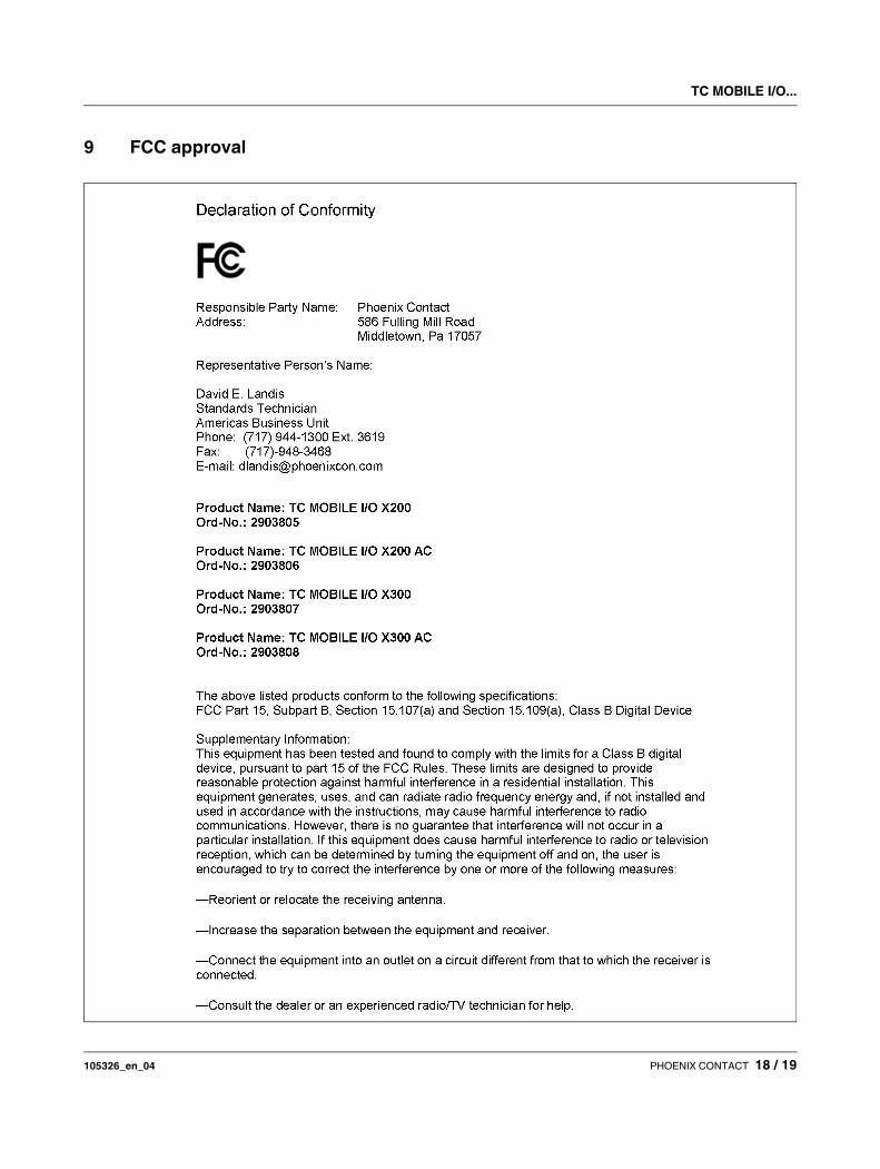
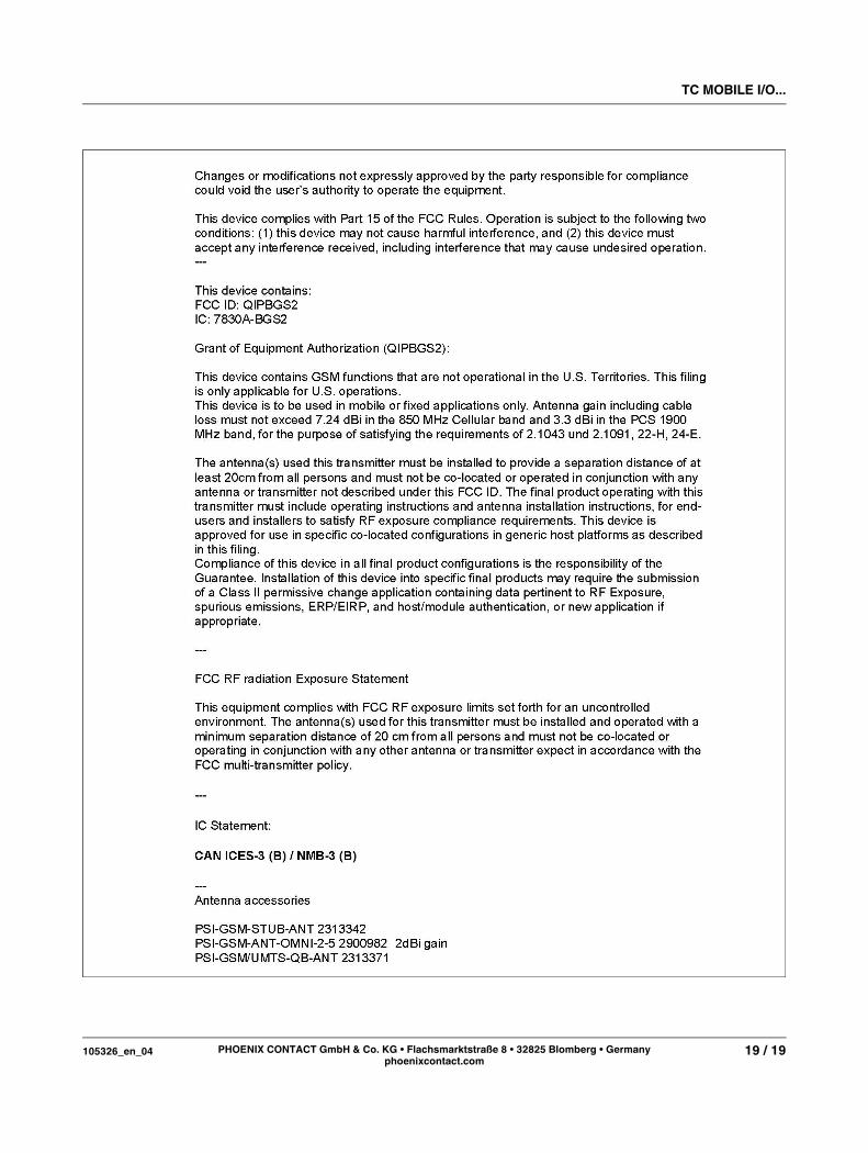
9 FCC approval
TC MOBILE I/O...
105326_en_04 19 / 19PHOENIX CONTACT GmbH & Co. KG • Flachsmarktstraße 8 • 32825 Blomberg • Germany
phoenixcontact.com