elec 2607 lab 3
DESCRIPTION
Elec 2607 Carleton uniTRANSCRIPT
ELEC 2607 Lab 3:The T-Bird Tail Light Control Using a CPLD
Jahed Bushnaq – 100890338Qais Al-Farsi – 100881878
Lab Section L8EDate Performed: March.3rd.2014Date Submitted: March.9th.2014
Introduction
The purpose of this experiment is to design a T-Bird tail light control, which is composed of 2 sets of lights, each containing 3 bulbs. The T-Bird light had 3 different situations, which are the signal, brake, and emergency flasher.
In order to get the desired situations, a divide-by-two-circuit was designed for the right control box and the left control box. The circuits were simulated and designed using a computer program, which was Xilinix ISE, which used another computer program called ModelSim that simulated and compiled the circuits then created a waveform to be downloaded on a programmable logic board. A programmable logic board (CPLD) was used to light the bulbs by downloading the circuits on it using the mentioned programs. Once the program was downloaded on the CPLD, the right signal, left signal, brake light, and emergency signal were implemented.
The T-Bird tail light control circuit implements the tail lights for a variety of vehicles in order to provide awareness and safety on the streets.
Specifications
The T-Bird tail light was implemented on Xilinix computer program. The schematic for circuits implemented on the Xilinix are shown in Figures 6-8. Figure 7 shows the schematic for the counter with the gates used to simulate it. Figure 3 shows the T-Bird control for the right and left control box.
The circuits mentioned above were compiled and then implemented using ModelSim program, which generated a waveform simulating the output for all the gates, which is shown in figure 4 in the appendix.
The simulation and the waveform for the tail light was downloaded on the programmable logic board CPLD which was able to show the result of each of the right signal, left signal, brake lights, and emergency signal.
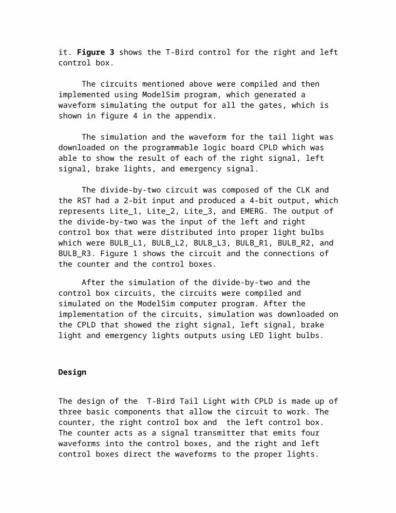
The divide-by-two circuit was composed of the CLK and the RST had a 2-bit input and produced a 4-bit output, which represents Lite_1, Lite_2, Lite_3, and EMERG. The output of the divide-by-two was the input of the left and right control box that were distributed into proper light bulbs which were BULB_L1, BULB_L2, BULB_L3, BULB_R1, BULB_R2, and BULB_R3. Figure 1 shows the circuit and the connections of the counter and the control boxes.
After the simulation of the divide-by-two and the control box circuits, the circuits were compiled and simulated on the ModelSim computer program. After the implementation of the circuits, simulation was downloaded on the CPLD that showed the right signal, left signal, brake light and emergency lights outputs using LED light bulbs.
Design
The design of the T-Bird Tail Light with CPLD is made up of three basic components that allow the circuit to work. The counter, the right control box and the left control box. The counter acts as a signal transmitter that emits four waveforms into the control boxes, and the right and left control boxes direct the waveforms to the proper lights.
A possible implementation of the T-Bird Tail Lights is shown below.
Figure 1. The interior of the counter divides the clock signal by two and sends out four different signals. [1, pp 2.]
The Counter
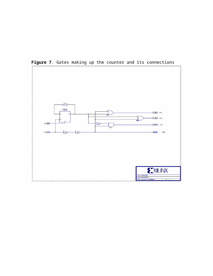
The objective of the counter is to receive an input from the clock, and a flip flop within the counter divides the input into two. This new frequency is half that of the clock frequency, while the counter still does receive the clock input as well. The divide by two circuit extends the waveform by two. Four different waveforms are sent out in the form of Emerg, Lite_3, Lite_2, and Lite _1.
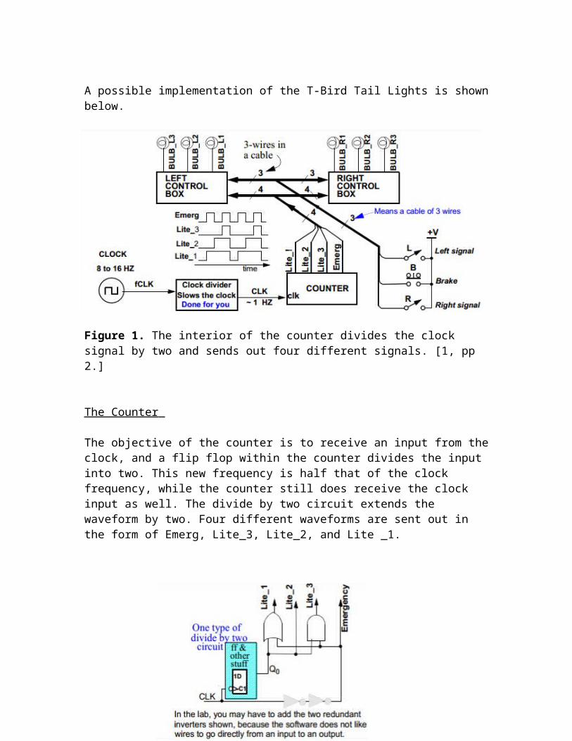
Figure 2. A Basic figure of how the counter deals with the four different signals are shown above.
The order in which the signals are sent out to the control boxes is determined by the counter, this task is important in ensuring that the right signals are sent to the control box in order for the proper lights to come on at the right time.
Table 1.
Qo CLK Lite_1 Lite_2 Lite_3 Emergency0 0 0 0 0 01 1 1 0 0 11 0 1 1 0 00 1 1 1 1 1
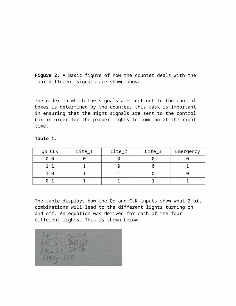
The table displays how the Qo and CLK inputs show what 2-bit combinations will lead to the different lights turning on and off. An equation was derived for each of the four different lights. This is shown below.
Figure 3. The four equations seen above are used for the counter circuit.
Using the equations seen above, a graphical representation of what the lights would look like in a schematic circuit can be seen below.
Figure 4. Schematic Circuit – The two inputs here are Qo and CLK.
The Right Control Box
The Right Control Box's main duty is to control the taillights of the right side of the car. It receives the signals from the counter, and according to what waveforms it receives, it will output a sequence of lights. The right Control box is made up of three outputs called Bulb_R1, Bulb_R2 and Bulb_R3.
The control box will output a flash signal, an emergency flash or the brake lights. In order to understand how the box determines what to output, a truth table is shown below.
Table 2.
B L R Flash Signal Emergency Flash Brake0 0 0 0 0 00 0 1 1 0 00 1 0 0 0 00 1 1 0 1 01 0 0 0 0 11 0 1 1 0 01 1 0 0 0 11 1 1 0 0 1
Table 2. The table shows when the different lights are used and what combination of the B-Brake, L-Left and R-Right ( B L R) allows the signals to be outputted.
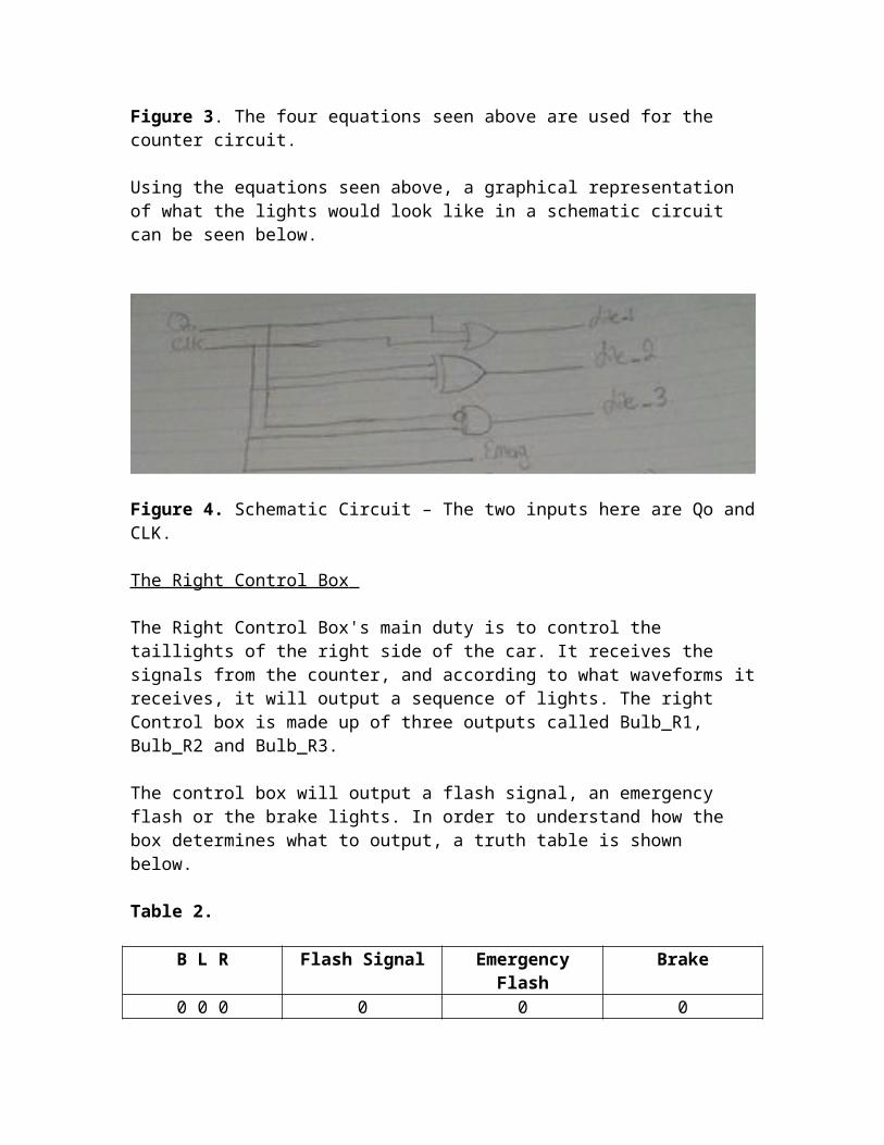
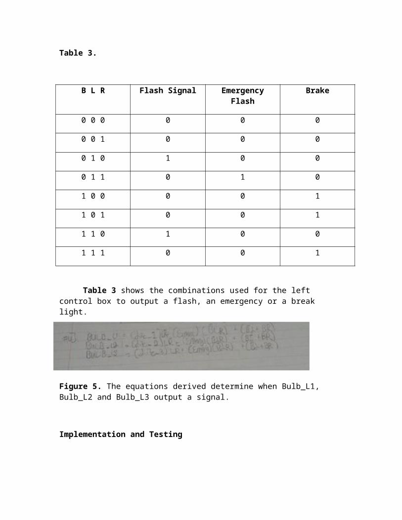
Figure 4. The equations that were derived determine when Bulb_R1, Bulb_R2 and Bulb_R3 output a signal.
The Left Control Box
The control duties on the left control box aren’t different of those on the right control box except now, it controls the taillights on the left side. The control determines what lights are to be outputted and in what sequence depending on the input from the counter box. The outputs in this case are there and are Bulb_L1, Bulb_L2 and Bulb_L3. The inputs are the outputs from the counter box.
The Truth Table for the Left Box is shown below.
Table 3.
B L R Flash Signal Emergency Flash Brake
0 0 0 0 0 0
0 0 1 0 0 0
0 1 0 1 0 0
0 1 1 0 1 0
1 0 0 0 0 1
1 0 1 0 0 1
1 1 0 1 0 0
1 1 1 0 0 1
Table 3 shows the combinations used for the left control box to output a flash, an emergency or a break light.
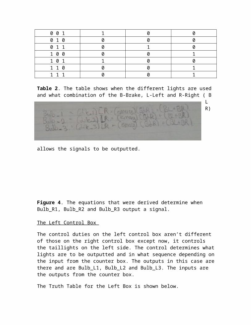
Figure 5. The equations derived determine when Bulb_L1, Bulb_L2 and Bulb_L3 output a signal.
Implementation and Testing
Conclusion
The required objectives and specifications of this lab were met. The Xilinix computer program was a useful tool that helped implementing the required circuits for the T-Bird tail light quickly and efficiently. Xilinix also played a major role in debugging the circuit in order to achieve the required outputs. Xilinix also helped making the wiring easier by making a neat wiring map and gates connections.
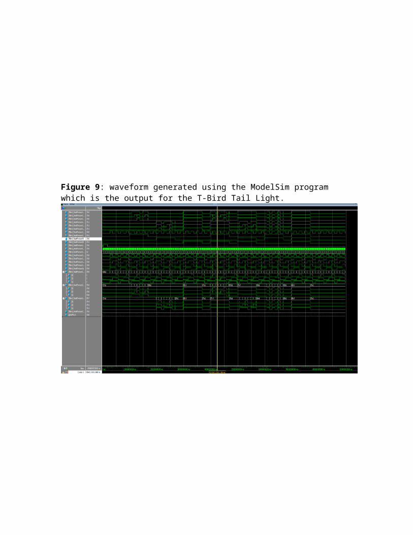
After compiling the connections and circuits with no errors, the ModelSim program was launched which generated a waveform shown in figure 4. The mentioned waveform shows the input and outputs for the circuits simulated on the Xilinix program. The output shown using the waveform matched the results and tables solved for in the pre-lab.
The CPLD showed a real life implementation of the logic gates, which play a huge role in maintaining the safety on the roads. Applying the T-Bird tail light show how the right signal, left signal, brake, and emergency signal are made and how they are implemented which was interesting.
Appendix:
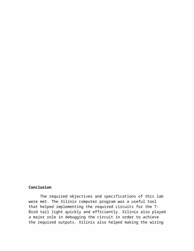
Figure 6. Top view of the T-Bird tail light circuit and connections
Figure 7. Gates making up the counter and its connections
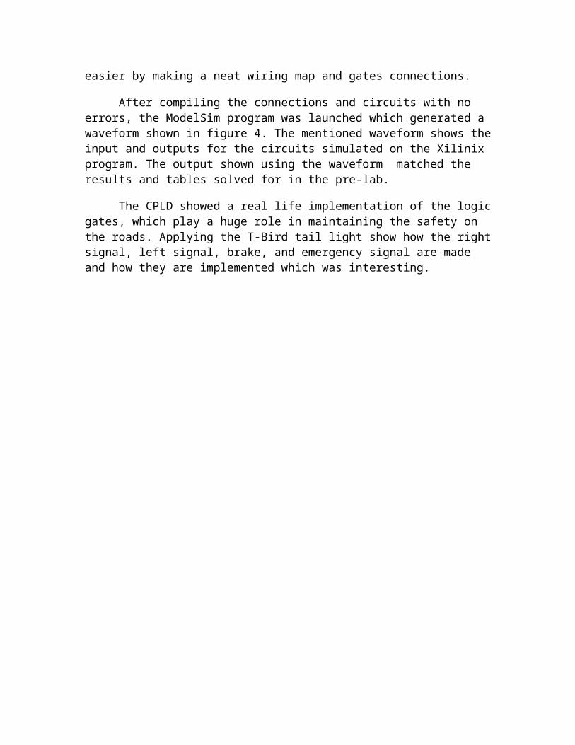
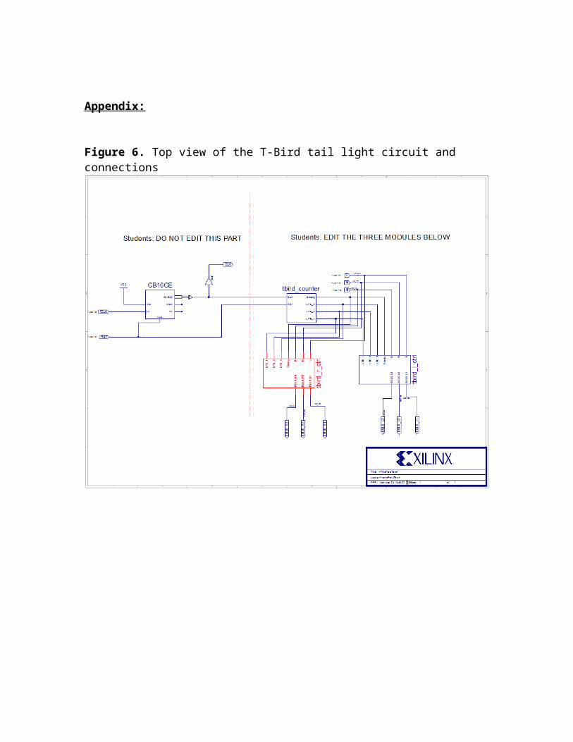
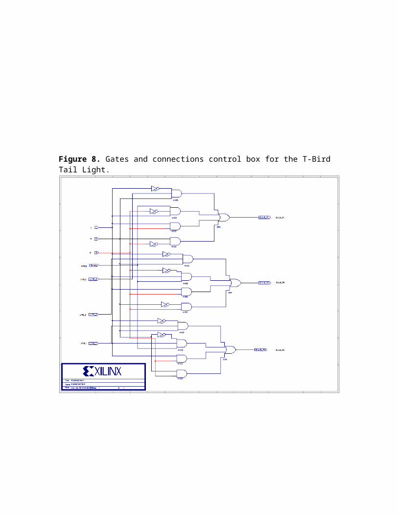
Figure 8. Gates and connections control box for the T-Bird Tail Light.
Figure 9: waveform generated using the ModelSim program which is the output for the T-Bird Tail Light.
Pre-Lab: