eis 447 aa052 395 drayton coal mine: mine development proposal
TRANSCRIPT

EIS 447
AA052 395
Drayton Coal Mine: mine development proposal

OPMENT PROPOSAL
INSW DEPT PR1M? INUSTRIES
AAO 52395
I
I DRAYTON COAL MINE
I MINE DEVEL
I
I
I
I
THSS
DRAYTON CO-VENTURE

H

I I I I I I I I I I I I I 1 I 1 1 I I I
THIESS BROS. PTY. LIMITED
AND
THE SHELL COMPANY OF AUSTRALIA LIMITED
DRAYTON CO-VENTURE
DRAYTON COAL MINE
MINE DEVELOPMENT PROPOSAL
JUNE 1978

1 CONTENTS
I I SUMMARY
INTRODUCTION
LOCATION
I
1.1
1.2 TOPOGRAPRYANDCLIMATE
GEOLOGY
2.1 COAL RESOURCES
I3. MINING PROPOSAL
3.1 SUMMARY OF EXTRACTION SEQUENCE
3.2 PIT LAYOUT
I MAJOR EQUIPMENT SELECTION
I
3.3
3.4 MINING RESERVES
1 I 3.5.1 West Pit
3.5.2 East Pit
Geotechnical Considerations
I
3.5.3
3.6 MINING OPERATIONS
3.6.1 Site Preparation
3.6.2 Overburden, Coal and Parting Preparation
I 3.6.3 Shovel/Truck Overburden Removal
1 (I)
Page
1
3
3
4
5
5
8
8
'ii
11
12
12
13
14
15
15
15
15

Page
3.6.4 Coal and Parting Extraction 16
3.6.5 Manning Levels 17
4. COAL QUALITY 18
4.1 PRODUCT QUALITY 20
4.2 QUALITY CONTROL 22
5. COAL HANDLING, TRANSPORTATION AND DESPATCH FACILITIES 24
5.1 LOCATION 24
5.2 COAL PRODUCTS 24
5.3 SCALE AND TIMING OF COAL HANDLING FACILITIES 25
6. PIT HEAD ESTABLISHMENT AND PROVISION OF SERVICES 27
6.1 ELECTRIC POWER SUPPLY AND RETICULATION 27
6.2 WATER SUPPLY AND TREATMENT 27
7. ENVIRONMENTAL IMPACT 28
8. COAL TRANSPORT 31
8.1 RAILTRANSPORT 31
8.2 PORT FACILITIES 31

1 I 1 I I I I 1 I I I I I I I 1 I I I I
FIGURES
1 Locality Map
2 Hunter Valley Coalfield - North West District
Location of Colleries
3 General Arrangement
4 Balmoral Seam Main Split (B3)
Geological Structure
5 Typical Stratigraphic Sections
6 Plan of NW Pit at End of Year 5
7 Mine Stage Development Plan
8 Open Cut Mining Plan
9 View of West Pit
10 Viewof East Pit
11 Restoration Plan
12 Typical Cross Section - East Pit
13 Typical Cross Section - West Pit
14 Elements of Quality Control
15 Pit Head Layout
16 Overland Conveyor, Trestles and Bridge
17 Train Loading Station
18 Newcastle Harbour Location Plan
19 Schematic Layout of Ship Loading Facilities at Newcastle
TYPICAL SPOIL DIAGRAMS - EAST PIT
20A Cuts 1E to 5E
20B North Cuts 6E to 18E - Stages 1 and 2
20C North Cuts 6E to 18E - Stages 3 and 4
TYPICAL SPOIL DIAGRAMS - WEST PIT
21 A South Cuts - Stage 1 and 2
21 B South Cuts - Stage 3 and 4
22 Development Schedule Summary

TABLES
No. Title
1 Summary of Total In Situ Geological Coal Reserves
2 Summary of Mine Quantities
3A Open-cut Mining Reserves - West Pit, North West Pit
313 Open-cut Mining Reserves - East Pit
4 Mine Production Schedule
5 Saleable Coal Tonneage
6 Maximum Number of Site Plant and Equipment
7 Utilization of Major Stripping Equipment
8 Annual Manning Schedule
9 Manning Table for Full Production Operation
10 Mine Site Staff
11 Summary of Physical and Chemical Properties

I I 1 I I I 1 I I 1 I I I I I I I I I I
No.
1
2
3
4
APPENDICES
Title
Major Equipment Specifications
Dragline Production Estimates
Shovel/Loader Production Estimates
Overburden, Coal and Parting Preparation
(V)

I
1
I SUMMARY
This development proposal outlines the conclusions of a detailed feasibility study
completed in January 1978 which investigated the extraction, preparation and
transportation of coalfrom the proposed Drayton Coal Mining Lease. The open
cut mining proposal, representing the optimum economic development in both
resource utilisation and commercial terms, is summarised below:
Location
The resource is located approximately 12 km. south of the town of
Muswellbrook and adjacent to the existing Bayswater No. 2 Open Cut Coal
Mine.
Coal Resource
Within the lease area coal reserves are:
Measured 96.8 million tonnes
Indicated 42.9 million tonnes
Inferred 79.0 million tonnes
TOTAL 218.7 million tonnes
Open Cut Coal Reserves
Coal reserves available to open cut mining are as follows:
In-situ coal 57,858,000 tonnes
In-situ overburden 225,249,000 m
Raw Coal to be mined 52,943,000 tonnes
Overburden to be removed
- Shovel 119,533,000 m
- Dragline, prime 109,510,000 m
- Dragline, rehandle 44,247,000 m
- TOTAL 273,290,000 m3
Ratios (m3/tonne)
In-situ Overburden 3.89 In-situ coal
- Tota Overburden to be removed (excl. rehandle) 4.33
Raw coal mined
Coal Quality
The coal is primarily a high quality steaming coal with low ash, high specific
energy and medium sulphur content.
Mining Mejhod
The multi seam resource will be recovered using a combination of an electric
walking dragline of 44.3 m bucketcapacity plus several shovel/dump truck
fleet combinations employing both electric and diesel hydraulic shovels.
1 I I I I I I I El I 1 1 I I E I I I

2
e Mine Life and Planned Production
The proposed development will have an assured life of 22 years although
additional reserves are available to extend the mine life beyond the year
2000. Raw coal production levels will be attained in the following key
stages:
- stripping overburden by electric shovel 1.0 million tonnes per annum
- after commissioning electric dragline 2.9 million tonnes per annum
- peak production rate 3.5 million tonnes per annum
S Environment
The mine is located in an area with a history of open cut coal mining and
cleared land cattle grazing. A Draft Environmental Impact Study in ac-
cordance with State Government Statutory requirements is being prepared
in association with the mining proposal. Consultants, Dames and Moore,
have been engaged to carry out this work on behalf of the Co-Venture. A
preliminary review of environmental factors has been completed by Dames
and Moore.
Marketing
A total of 52.9 million tonnes of raw coal is to be mined. In accordance
with marketing requirements, coal handling and preparation plant designs
have been developed for up to three product types. Two alternative de-
signs cater for:-
Indicative Annual Production
(millions of tonnes)
- STEAM COAL PRODUCT
Steaming coal products comprising a
"high" ash (10% - 15%) and a "low"
ash (lessthan 10%) type. 2.9
- STEAM COAL/COKING COAL PRODUCT
Steaming coal products of "high" and
"low" ash, as above, plus 2.2
A hard/soft coking coal product. 0.6
Start of Development
Mine development will commence in the financial year 1979 - 80 with peak
coal production being achieved in 1990. This production schedule is de-
pendent on the electric dragline being commissioned during 1983. Con-
ceptual design of the coal handling plant and mine establishment complex
has been completed by Crooks, Michell, Peacock, Stewart Pty. Ltd. (C.M.
P.S.), Engineering Consultants, in association with the co-venture study
team. Design of these facilities will be refined after testing of further bulk
samples.
The target development schedule is presented in Figure 22.

I
1 I I I [1 I I I I I 1
3
INTRODUCTION
Interest in the Drayton Mine area, formerly known as the Balmoral area, was established in 1951, when Thiess Bros. Pty. Ltd., lodged exploration applications in accordance with the provisions of the New South Wales mining legislation. Since that time, exploration programmes conducted under the auspices of the Joint Coal Board, the New South Wales State
Electricity Commission and Thiess Bros. Pty. Ltd. have been carried out.
During 1977, The Shell Company of Australia entered into a co-venture
agreement with Thiess and acquired a 44.5% interest in the proposed
Drayton Mine. The Drayton Co-Venture participants have purchased the surface rights to
874.8 hectares and are negotiating for additional land purchases within the
proposed lease area. In February 1977 an authorisation was obtained for
additional exploration activities which includes an excavation to enable bulk coal samples to be extracted.
Since the lodging of the initial applications, Thiess has carried out a num-
ber of investigations aimed at increasing the detailed knowledge of the area in respect of:
the geology of the coal measures,
the reserves available for open cut and underground mining methods,
the quality of the saleable coal product which could be offered for
export,
applicable mining method alternatives as well as the associated coal
handling, benefication and transportation options.
Following the signing of the Thiess/Shell Co-Venture agreement in 1977,
it was decided to proceed to a detailed study of the Drayton Area. The
first stage of this work was the preparation of the Drayton Geological Re-
port in the last quarter of 1977 and the second stage was the completion
of a definitive Mining Feasibility Study in January 1978. An excavation
to allow extraction of bulk samples of the Balmoral seam commenced in
February 1978 and will be completed in July 1978.
1.1 LOCATION
The Drayton Mine area is located in the Upper Hunter Valley district
of New South Wales, approximately 10 kilometres south-east of the
town of Muswellbrook, 125 kilometres from the city of Newcastle,
and 290 kilometres north of Sydney. (Refer Figure 1) The closest
malor settlement is Muswellbrook, a well established expanding rural
town with a population of approximately 10,000 people.
Transport services between Muswellbrook and Sydney are via a major
highway, arail link and air services to Scone (24 kilometres north of
Muswellbrookj, and Singleton (40 kilometres south of Muswellbrook).
The Drayton area is situated close to the main Northern Line of the
I Li I I I I I

21
New South Wales railway system. A site close to Antiene Station, a
distance of 8 kilometres by road from the mine area, has been chosen
for the construction of a rail loading facility. The rail distance from
the proposed Antiene siding to the Port of Newcastle is 114 kilometres.
Access to the site is made from the east via an all-weather unsealed
road, which adjoins the New England Highway, 11 kilometres south
of Muswellbrook. The Drayton Mine area is traversed NW-SE by a
bitumen sealed stockroute road (Refer Figure 3).
1.2 TOPOGRAPHY AND CLIMATE
The Drayton area is characterised by a central N-S to NW - SE trending
ridge along which elevations above sea level generally range from 250
to 300 metres (rising to a maximum 330 metres), and from which a
number of watercourses drain. Elevations above sea level along the
eastern boundary of the Drayton Mine area average approximately
180 metres, falling to a minimum 160 metres on the ash dam. Most
of the Drayton area is cleared or semi-cleared and used for general
grazing purposes. A small area near the proposed initial mining area
is subject to occasional cultivation and a few irregular scrub timber
stands, mainly on the steeper slopes, are scattered through the area.
The area experiences a warm temperate climate with hot maximum
summer temperatures (mean maximum for December 29.10 C.), and
cold to mild winter temperatures, (mean minimum for July 1.80 C.).
Annual rainfall averages approximately 600 mm. with heavier falls
generally occurring during the summer months November - March.

1 2. GEOLOGY
Regionally, the Drayton Mine area lies in the Muswellbrook-Balmoral inlier
I of the Lower Permian, and is situated in the extreme NE of the Permian-
Triassic Sydney Basin, some lOkilometres west of the Hunter Thrust System,
I which defines the NIE boundary of the basin.
The Lower Permian Greta Coat Measures in the Muswelibrook-Balmoral
area, crop-out along the approximately north-south trending crest of the
I Muswellbrook Anticline, a major gently southwards plunging structure
which traverses the Drayton Mine area. The Greta Coat Measures in the
Iarea are subdivided into two formations:-
The upper Rowan Formation, approximately 115 metres thick,
consists of sandstones, siltstones, shales and coal seams. Figure 5
I illustrates the two respresentative stratigraphic columns of the Greta
Coal Measures in the Drayton Area. The major coal seams occuring
I include the Brougham, Grasstrees, Puxtrees and Balmoral series. The
Puxtrees series includes the Thiess coal split.
I. The lower Skeletar Formation, approximately 100 metres thick,
consists of tuffaceous and pelitic shales and clays, cherts, and rhyo-
lites. The formation is overlain by the Rowan group.
I Many of the Upper coal seams in the Muswellbrook Anticline area have
been impaired by the effects of faulting and intrusive igneous sills and dykes.
I The most significant fault affecting initial mine planning at Drayton is a
NNE trending, normal, strike slip fault, located approximately 300 metres
west of the Muswellbrook Anticline axis. The throw of the fault ranges
I from 10 to 20 metres with a downthrow to the West.
The effect of igneous activity in the Drayton area is confined to intrusive
I sills and associated neighbouring coal seam alteration. Intermediate to
basic intrusive sills occur in the far northern, and north western and south
eastern corners of the area. However the Balmoral coal member which
1 contajns the major part of the coal reserves at Drayton is completely un-
affected by igneous activity within the limits of the proposed mining area.
I 2.1 COAL RESOURCES
Prospecting operations in the area date back to 1952. Exploratory drilling
Ito date totals 311 holes with approximately 19,500 metres of drilling in-
cludrng some 13,700 metres of coring. Three shafts have been sunk to
obtain bulk coal samples for testing. The mineable coal seams present, to-
I gether with their average thicknesses, are listed from top to bottom as
follows:-
I I I

Series Seam Idtification Average Code of Thickness
Mineable Section (metres)
Brougham Brougham Upper Split R2 1.6
Brougham Lower Split R3 1.6
Grasstrees Grasstrees Middle Split G4 1.4
Grasstrees Lower Split G5 0.7
Puxtrees Thiess Seam T2 2.3
Puxtrees Main Split P2 1.9
Balmoral Balmoral Savoy Split B1 1.8
Balmoral Main Split B3 5.8
In the southwest part of the mine area (the West Pit), the Balmoral Main Split
divides forming the Balmoral Main Split Upper (1331) and Balmoral Main Split
Lower (1332) seams with average thicknesses of 3.3 metres and 2.7 metres res-
pectively. The Balmoral Savoy Split also divides in the same area forming the
Savoy Split Upper (Bli) and the Savoy Split Lower (B12) with average thick-
nesses of 1.2 metres and 0.8 metres respectively.
Total measured, indicated and inferred geological coal reserves within the Mining
Lease Boundary are summarised in Table 1. The selected open-cut mining areas
are contained within the measured reserve areas of the East and West Block, and
the mining reserves are derived from the major coal seam horizons as follows:-
Series %of Mining Reserves
Brougham 9
Grasstrees 6
Thiess 11
Puxtrees 9
Balmoral 65
Laboratory testing of the Drayton coal seams has been conducted by a number
of organisations, including:-
Joint Coal Board
Commonwealth Scientific Industrial Research Organisation (CSI RO)
o Australian Coal Industry Research Laboratories (ACIRL)
Yawata Steel Mills (Japan)
A summary of the results from these testing programmes is given in Table 11.
These allow the following conclusions to be drawn in respect to the coal resource
potential of the Drayton Area:
Coal seams other than the Thiess seam are high quality steaming coal
with low ash, high specific energy and medium sulphur contents.
The Thiess seam is a high volatile coking coal.
The petrographic composition of each of the seams overlying the
Balmoral series indicates that they may possess some soft coking pro-
perties. This point is to be subject to further investigation.

1 I 1 1 I I 1 I I I I I I I I I I I I I
KA
Regionally, the Upper Hunter Valley isan important coal resource area and many
opencast and underground mining operations have been developed in the last 20
years. Figure 2 is a map showing the distribution of the mining activity already
established in the neighbourhood of the Drayton Mine Area.

FI
3. MINING PROPOSAL
Three areas, the North West, the West, and the East, have been identified as
open cut mining blocks. These mining blocks have the following general
characteristics: -
Each contains multiple seams with the East and West blocks containing
up to seven mineable seams including some with multiple splits.
The thinner seams occur in the upper section of the measures, e.g. the
Grasstrees series,
The thickest coal seam, the Balmoral, is the lowest in the sequence,
Seam dips range between 00 14°.
A flexible, selective mining method is essential to ensure maximum
extraction of reserves and to allow the production of saleable run-of mine
(raw) coal. A number of alternative mining methods were studied and it was
concluded that the Drayton area should be mined as an open cut with three
separate pits employing a combined shovel/truck and dragline operation for
overburden removal. These are hereinafter referred to as the West Pit, the
North West Pit, and the East Pit, with the latter two Pits being contiguous.
3.1 SUMMARY OF EXTRACTION SEQUENCE
The extraction sequence to be followed will be:-
0 Establishment of a shovel and truck overburden stripping operation
in the North West Pit.
A second shovel and truck stripping operation will then develop
the West Pit box cut in preparation for the introduction of an
electric walking dragline.
The dragline will later be complemented by the shovel and truck
operation exposing the upper seams as required.
After completing the overburden stripping in the North West Pit,
the shovel and truck combination will open up a box cut on the
anticlinal axis in the East Pit,and then pre-strip down the eastern
flank of the anticline in preparation for the dragline sidecasting
operation.
When the West Pit stripping is completed the dragline will move to
the East Pit initially cross-dragging from the box cut down the
west flank of the anticlinal axis and later working eastwards.
3.2 PIT LAYOUT
Pit layout was determined essentially by the structure of the deposit
to be mined, the geometry of the major extraction equipment alterna-
tives, and the method of operation. Strike cuts were preferred with
strata dipping into the highwall where possible because they provide
the longest uninterrupted working horizon, immediate access to the
coal with the lowest overburden ration suitable for dragline overburden

I I stripping and a reasonable assurance that no significant geotechnical
problems would occur.
1 NORTH WEST PIT
Cuts were oriented as close as possible to the strike of the seam with the
initial box cut being located in the lowest overburden to coal ratio area.
I The cut widths were determined by shovel and truck dimensions and method
of operation. The main access ramp into the pit runs in a W-E direction
I and overburden excavated in the ramp forms part of the pre-strip overburden
for the East Pit. ' WEST PIT
The West Pit cuts were orientated parallel to the western Mining Lease
boundary as this permitted:
I • Maximum cut lengths;
The ability to extend the north and south pit limits should further
I exploration prove this feasible;
A central access ramp splitting the cuts into north and south;
I. The opportunity to work the higher ratio south cuts in conjunction
with the lower ratio north cuts; -
I. Easier scheduling of in-pit operations;
Elimination of shovel and truck pre-stripping work during the first
two years of dragline operation;
I • Progressive rehabilitation to be carried out from the Mining Lease
bou ndary.
I EAST PIT
The East Pit cuts were orientated in a N-S direction as this permitted:
I. Maximum cut lengths for ease of equipment scheduling;
The option of extending south through the fault if reserves are
I proven to be economic;
The option of extending the pit beyond the eastern limit, if exten- sion proves economic. - A . central access ramp to the Balmoral seam;
o Minimum box cutting to ensure continuity of coal during East Pit
Idevelopment.
I3.3 MAJOR EQUIPMENTSELECTIQN
Major equipment capacity and geometry was selected after detailed
study of the alternative mining strip layouts, mining schedule and
I the economics applicable to alternative available equipment.
I I

10
DRAGLINE SELECTION
After detailed examination of:-
The average production rates and geometry, in particular dumping
heights and operating radii, of available draglines;
The proportion of overburden (and rehandled overburden) handled
by the dragline compared to the total overburden to be mined;
The average overburden/coal ratio in the mine area;
The in-pit operations such as drilling and blasting, coal and parting
removal that would also have to be scheduled along with the dragline
operation.
It was determined that a dragline of 44m3 (58yd 3) bucket capacity would
provide the lowest operating unit cost for a mine production in the range
of 2 - 3 m.t.p.a.
STRIPPING SHOVEL SELECTION
To maintain a flexible, selective mining method several shovel/dump truck
fleet combinations employing both electric and diesel hydraulic shovels are
used to excavate the overburden from the following sources:
All the overburden in the North West Pit;
Overburden from the initial box cuts in the West and East Pits;
Pre-strip overburden in advance of the dragline operation.
For the initial mining operation commencing in the North West Pit a 7.6m3
hydraulic excavator was selected because it was:
Best suited to the desired early production rate,
Easily transferrable to the West Pit to open up the initial box cut
without the need for site electrical reticulation,
Best suited to coal loading operations in the West Pit after the
introduction of the dragline,
Suitable for the overburden pre-stripping necessary in the West Pit
after the first two years operation with the dragline.
A 16m3 (21yd3 ) electric shovel was selected for introduction in the second
year of operation the North West Pit, to allow increased coal output.
For operations in the East Pit the proportion of shovel/truck overburden
increases and both the 7.6m3 hydraulic excavator and the 16m3 electric
shovel are required to pre-strip overburden from the upper seams in advance
of the dragline. Any subsequent reference to specific manufacturers' equipment models is
to assist readers to understand the nature and type of equipment, and in no
way indicates any commitment to, or preference for, particular manufact-
urer's products.

Li
11
3.4 MINING RESERVES
The determination of the overall pit layout and the choice of strike-
orientated cuts allowed a preliminary mine plan to be prepared, from
which reserves were calculated on a cut by cut basis. In calculating
the mining reserves it was necessary to identify the seams which were
mineable either individually or as a combination of seam splits,
where both the coal and parting would be mined together. Two
principal constraints were applied in the vertical selection procedure,
namely coal quality, and the ability tomine a particular coal/parting
interval with the equipment available. Specifically the constraints
applied were:-
A simple coal quality constraint whereby mining seam hori-
zons are to have a maximum 15% raw coal ash.
A minimum mineable seam thickness of 0.75 metre.
If the parting between two mineable seams is less than 0.5
metre, the seams and parting are to be combined to become
one mining horizon.
If the parting between two mineable seams is greater than
0.5 metre thick, the seams are to be treated as separate
mining horizons.
The vertical seam selection procedure allowed the mineable seam
intervals to be identified and this information, together with the
geological interpretation of the Drayton Area, was used to con-
struct 24 E-W oriented cross sections, at regular intervals through
the deposit. Ratio and reserve estimation was based on the
determination of the quantity of the situ-coal and overburden
between each pair of cross sections. In order to determine strip
quantities for phasing of the operation, the mining strips and seam
benching patterns adopted in the mining plan were superimposed on
the cross sections.
The overburden and coal quantities determined made allowance for
pit end wall batters and benches as shown in the mining plan.
Volumes of cindered or burnt coal were included in overburden
quantities. Although not included in the reserve base the volume
of potentially recoverable cindered coal was assessed at approxi-
mately 1.3 million m. In estimating the quantities of mineable
coal, the depth of coal weathering was considered. Examination of
the overburden weathering distributions resulted in the exclusion of
all coal from the mining reserves which was at a depth of less than
10 metres in the West Pit, 15 metres in the East Pit, and less than
20 metres in the North West Pit.
I I
1 I I Li I I I I I I I I 1 I I I
I

To allow for coal losses during mining operations, the in-situ coal
reserves were depleted by a value determined according to the
major excavating machine uncovering the coal seam. The following
constraints were app lied:-
For seams stripped by the shovel/truck overburden operation
(132 and G4) 20 cms of the seam thickness will be lost.
For seams stripped by a parting removal operation (R3 and
G5) 15 cms. of the seam thickness will be lost.
For seams or splits of seams uncovered by the dragline
25 cms. of the seam thickness will be lost.
For all splits within the Balmoral seam 15cms. of each split
will be lost. This was not the case for parting removal by
the dragline in the south cuts of the West Pit, where a loss
of 25 cm. coal was adopted.
The resulting overburden and coal quantities are shown in Tables 2,!
3A and 3B and these quantities were the basis of the production:
schedule in Table 4.
3.5 DRAGLINE MODE OF OPERATION
Because of the complexity of the deposit and the large variation in
parting and interburden thickness the dragline mode of operation
varies between pits. It is anticipated that the hardest overburden
for drilling, blasting and excavating will be the Balmoral Sandstone
which lies between the P2 and Bi seams. In both pits this material
is handled by a conventional inline dig and side cast operation
in preference to the more difficult chop-down method.
3.5.1 West Pit (Refer Figure 9)
The cuts are conveniently divided by a central access ramp,
initially exitting through the highwall for the box cut and
the first two dragline cuts, and then being routed through
the low wall spoils for the remaining cuts. The mining
method involves the dragline digging alternate north and
south cuts starting from the central ramp. A cut width of
50 m. is best suited to the multiseam application whereas a
wider cut gave a lower rehandle figure in the single seam
situation.
In the south cuts the parting between the Bi and B31 coal
varies between 4-5m. and a method of working was designed
to enable the dragline to dig this parting from a low wall
bench. The mode of operation for the south cuts is shown
in Figures 21A and 21B and involves one traverse of the
- cut with the dragline sitting on the highwall side and two
on the spoil bench.

I
13
In the north cuts ithe parting between the Bi and B31 coal
varies between 3-4m. and is removed by an in-pit shovel/
truck operation. The method of dragline operation in the
north cuts is basically a conventional bridging method. A
ramp is formed at the north end of the cuts rising from the
P2 to the G5 level. This gives an exit road for the dragline
after completing stripping to the Bi seam and enables it to
walk back along the G5 bench to start stripping operations
in the next south cut. It also prOvides access for coal
removal from the T2 and P2 seams when the progressive
dragline operation cuts off the road along the highwall
benches. After completing cut lOW the dragline is tempor-
arily transferred to the East Pit until all coal and partings
are removed. The same procedure applies for cuts 11W and
12W and then upon completion of the final cut, the machine
is moved to the East Pit.
East Pit (Refer Figure 101
The initial dragline work in the pit requires cross-dragging
from the anticlinal box cut down the west side of the
anticlinal axis.
To expose the steeply dipping Balmoral seam down the
east flank of the anticline a conventional bridging method
will be adopted. A 70m wide cut is used, this having the
advantage of slowing down the rate of advance of the
dragline and creating more working space in the cut, with-
out increasing the percentage of overburden rehandled.
The North West Pit low wall benches and ramps provide a
convenient access route down to the coal in the initial
dragline strips in the East Pit. With increasing depth of
operations and backfilling of the final North West Pit void
by the East Pit shovel/truck pre-strip material a central
ramp through the spoil (designed on a 10% grade) provides
continued access to the Balmoral coal. As in the West Pit
the dragline commences stripping at the central ramp and
completes its operation at the north and south pit lmits.
For the first five dragline cuts all overburden above the P2
level is removed by shovel and truck. From cut 6E to 18E
a shovel/truck operation removes all overburden down to
the G5 level and the dragline removes the remaining over-
burden to the Balmoral seam. (Refer Figures 20A to 20C)
Commencing from the central access ramp and
progressing north, the dragline digs from the G5
level to expose the T2 coal.
I 1 I I I I [1
3.5.2
I I I I 1 I I I I I I I

14
After completing this operation the dragline walks
back along the G5 bench and down the central
highwall ramp to sit at the P2 bench level.
At this horizon the dragline "chops" all the T2-P2
partings, digs a key cut in the P2 to Bi overburden,
and sitting out on the spoil bridge digs the remain-
ing overburden exposing the Bi coal.
When reaching the end of the cut the machine then
walks back along the P2 bench to the central ramp
and the same procedure is repeated in the south
cuts.
This mining method was adopted after detailed considera-
tion of various alternative dragline operations. The
advantages of this method of operation are that:-
0 Scheduling of overburden preparation, and coal
and parting removal is simplified,
Overburden preparation can always be carried out
well in advance of the dragline,
o Linear advance along the cut is slow, avoiding
crowding of the coal extraction operations and
allowing the opportunity to blend coal from the
various seams.
3.5.3 Geotechnical Considerations
Highwall batters and low wall spoil angles were initially deter-
mined after observation of these parameters in the neighbouring
Bayswater Mine where the same geological sequence occurs. A
preliminary geotechnical investigation completed by the consul-
tants, Dames and Moore, substantiated the assumptions made.
Two geotechnical boreholes have been drilled and core samples
tested and further geotechnical studies are being carried out in
association with the completion of the bulk sample excavation.
For the purpose of assuring spoil pile stability in the multiseam
operation in the East Pit,a 25 metre bench will be formed in the
spoil at the dragline bridge level. This bench may be used as a
haul road by having a ramp running (parallel to the cut) from the
bench down to the Balmoral seam. The ramp would enable
Balmoral coal to be hauled up and along the spoil bench, across
the end wall bench and out through the highwall upper seam
:ramp to the Pit Head.
Tight scheduling in the West Pit restricts the dragline to working
on a five day week basis. This situation applies until the multi-
seam operation commences in the East Pit when the dragline can
then be scheduled for a seven day week basis. Dragline specifica-
tions and production estimates are shown in Appendices 1 and 2.

I
15
3.6 MINING OPERATIONS
3.6.1 Site Preparation
Before mining operations commence all 'necessary site
preparation will be carried out. This will involve the
stripping and stacking of all topsoil from areas disturbed by
tips and associated facilities and initial mining areas. Topsoil
dumps will be positioned so as to provide visual screens and
noise barriers where these are considered necessary. Settling
ponds will be formed where the natural topography drains
surface water from the site, ensuring that any water leaving
the site will be within acceptable quality limits.
Before commencing operation in the West Pit the stock
route will be diverted along the Western Lease boundary to
join back into the existing route east of the South Tip.
3.6.2 Overburden, Coal and Parting Preparation
Overburden drilling and blasting for the shovels and dragline
is scheduled to remain well in advance of the excavating
equipment. The mining method adopted has been designed
to minimise "peak" drilling demands. Drill rigs have been
selected on the basis of suitability of app'ication. (Refer
Appendix 4)
It is anticipated that explosives will be purchased direct
from the ICI Explosives depot at Liddell which has bulk
ANFO and Slurry trucks available for "down -the-h ol e"
deliveries. Estimates of blasting patterns are shown in
Appendix 4.
3.6.3 Shovel/Truck Overburden Removal
The initial shovel/dump truck operation will start in the
North West Pit with a 7.6m3 hydraulic excavator loading
overburden into 85 ton rear dump trucks. Overburden from
the box cut and following cuts will be trucked to the East
Tip until progressive backfill of the working pit commences.
Because of the increasing length of cuts and depth of over-
burden, the backfill void created will only take a proportion
of the annual quantity of overburden removed and the
remaining material will go to the tip.
Commencing year 2, the hydraulic excavator will be trans-
ferred to start the box cut in the West Pit and a 16m3 (21yc13)
electric shovel loading into 120 ton rear dump trucks will
be introduced in the North West Pit. Shovel working
benches are designed for 30 metres in width which gives a
60 metre working area as each cut is excavated. End wall
benches and backfill benches are designed to give progressive
I I I I I Li I 1 I I I I I I I I I I I

16
backfilling of the mined out areas. Figure 6 shows the
working pit with highwall and backfill benches at the end
of year 5.
The overburden from the box cut in the West Pit will be
trucked to the South Tip along an access ramp out through
the highwall. Further pre-stripping in this Pit will not be
necessary until the dragline has completed two full years of
operation and during this period the hydraulic shovel and
associated trucks will be used on coal and parting removal.
When pre-stripping becomes necessary, a hydraulic excavator
will be introduced together with the necessary 85 ton dump
trucks and the pre-stripped overburden will be trucked
around the end of the dragline cuts to restore the spoil area
behind the dragline.
Upon completion of the North West Pit the electric shovel
will be transferred to the East Pit to dig a box cut down the
anticlinal axis and then to pre-strip overburden down the
eastern flank of the anticlinal axis in preparation for the
dragline. The electric shovel will be supplemented by the
7.6m3 hydraulic shovel from the West Pit to keep the pre-
stripping in advance of the dragline.
Shovel/truck overburden from the south cuts in the East Pit
will be trucked over to backfill the worked out West Pit and
to restore the area to final surface contours. Overburden
from the north cuts will be trucked back into the North
West Pit and the dragline spoils area to progressively restore
from the Western Lease boundary.
Production estimates for the shovels and loaders are shown
in Appendix 3 and the mine development plan is shown in
Figure 7.
3.6.4 Coal and Parting Extraction
Due to the dip of the coal seams, hydraulic excavators of
4.5m3 and 7.6m3 (equivalent rock bucket) capacity were
selected for excavating the coal and partings. These excavators
will be used in both face shovel and backhoe configuration.
They will be supplemented by a 9m3 front-end loader to
assist in parting removal between the R2 and R3 seams and
the G4 and G5 seams.
Rear dump trucks of 50 ton and 85 ton capacity will be used
to truck the coal and partings with the 50 ton trucks
equipped with coal bodies and the 85 ton trucks a combin-
ation of coal and rock bodies. Rear dump trucks were
chosen in preference to bottom dump coal haulers for the
following reasons:
Gradients on some of the access ramps are considered
too severe for bottom dump haulers.

I
17
I . A flexible fleet will be necessary, as many of the
trucks will be required to carry both coal and
partings.
I . In areas with steeply dipping pavements in-pit man-
ouvreability will be improved.
Equipment selected for cleaning the top of the coal seam,
prior to drilling, and around the loading excavators are
rubber tyred dozers (e.g. Cat 824) except in the East Pit
where a hydraulic shovel with backhoe attachment is used
for coal loading due to the steep seam dips. Table 6 shows
a list of all equipment employed at the mine when operating
on full production.
3.6.5 Manning Levels
Manning levels were determined on a yearly basis. Table 8
shows the total labour build-up and annual variations while
Table 9 shows a detailed listing for year 13 of the opera-
tion. A similar listing of mine site staff is shown in Table 10.
All wage rates have been determined in accordance with the
awards under the Coal Industry Act 1946- 1973 as follows:-
The Coal Mining Industry (Miners) Award, 1973,
New South Wales.
The Coal Mining Industry (Engine Drivers and
Firemen's) Award, 1973, New South Wales.
The Coal Mining Industry (Mechanics) Award, 1973,
New South Wales.
The Coal Mining Industry (Deputies and Shotfirers)
Award, 1973, New South Wales.
The Collieries' Staff Award, 1973.
The Amalgamated Engineering Union.
I I I I I I
I I I 1 I I I I I 1
I

ii:
4. COAL QUALITY
Analysis of coal samples obtained during the various phases of exploration
has been conducted by several laboratories (refer Table 11), and the general
quality of the Drayton coal has been known for some time. However the
selective mining criteria developed in the feasibility study required a detail-
ed re-evaluation of quantity and quality of the coal in the selected mining
areas of Drayton. For the purposes of the re-evaluation the three mining
pit areas, the North West Pit, the West Pit and the East Pit were computer
modelled and studied in detail.
NORTH WEST PIT
A satisfactory computer model involving three Balmoral seam plies (Bi, B3
and 134) and two interburdens (131-133 and 133-134) was produced. The effect
of varying the cutoff thickness of the interburden waste on the overall coal
quality in the pit was examined and the following selective mining criteria
was adopted.
50 cm interburden cutoff thickness
5 cm dilution by waste per mining ply
20 cm top of coal loss
15 cm coal loss at each parting
Application of this mining criteria to the North West Pit computer model I generated the following coal quality predictions (as received basis).
IN SITU AS MINED STANDARD DEVIATION
Ash (%) 9.7 10.17 0.73
Total Sulphur (%) 0.83 0.83 0.03 1 Specific Energy (MJ/Kg) 28.17 27.96 0.55
WEST PIT I As for the North West Pit a computer model was developed and the parting
within the Bi ply of the Balmoral seam was identified as being of critical I thickness. The effect of varying the Bil - 1312 parting cut off thickness on
overall pit quality was examined in association with the iso-coal contour
plans, and the following selective mining criteria was adopted: I 50cm Bi 1 - B12 interburden cut-off thickness
5 cm dilution by waste per mining ply
20 cm coal loss for seams stripped by shovel/truck overburden
operation (Brougham, Grasstrees)
25 cm coal loss for seams stripped by the dragline (Thiess, I Puxtrees, Balmoral)
15cm coal loss for seam splits within the Balmoral seam (1331
and B32) and at the Bli - B12 parting. I
I

I I
Application of this criteria to the West Pit computer model generated the
following coal quality prediction (as received basis).
SEAM IN SITU AS MINED
Ash Specific Energy Sulphur Ash Specific Energy Sulphur % (MJIK9) % % (MJ/Kg) %
R3 9.07 28.76 0.96 11.17 27.86 0.94
STD. DEV. 1.52 0.39 0.15
G5 7.35 29.83 0.75 11.21 28.15 0.73
STD. DEV. 0.62 0.62 0.04
T2 6.69 29.63 0.87 8.99 28.65 0.85
STD. DEV. 0.76 0.34 0.06
P2 6.44 29.87 0.83 8.40 29.01 0.81
STD. DEV. 0.69 0.35 0.05
131 11.70 27.77 1.12 13.90 26.84 1.08
STD. DEV. 3.97 1.40 0.37
B31 10.50 28.06 1.04 11.84 27.49 1.02
STD. DEV. 1.90 0.85 0.31
B32 12.54 27.14 0.80 13.86 26.58 0.79
STD. DEV. 1.76 0.77 0.15
AVERAGE 10.54 28.10 0.95 12.34 27.34 0.93
STD: DEV. 1 2.14 0.86 0.23
EAST PIT
I As for the other pits a computer model was developed. No critical parting
was identified in the East Pit although close to the anticlinal axis the 64 ply
I
of the Balmoral seam is mineable as part of the B3 horizon. Only the first
nine cuts of the East Pit, which coincides with fifteen years of operation
on the current production schedule were modelled because the denisty of
I
data outside this area is too scarce to realistically form the basis of a com-
puter model.
The selective mining criteria used for evaluating the East Pit is consistent
I witi-1 that used in the West Pit and North West Pit i.e.
5 cm dilution by waste per mining ply
1 20cm coal loss for seams stripped by shovel/truck overburden
operation (Brougham, Grasstrees)
I 25 cm coal loss for seams stripped by the dragline (Thiess,
Puxtrees, Balmoral)
15 cm coal loss for B3 seam ply.
I Application of this criteria to the East Pit computer model generated the
fol lowing coal quality predictions (as received basis.)
I I
[1 I I 1 I I I I
I

AIJ
SEAM IN SITU AS MINED
Ash Specific Energy Sulphur Ash Specific Energy Sulphur % (MJ/Kg) % % (MJ/Kg) %
R2 9.15 28.75 0.80 10.99 27.97 0.78
STD. DEV. 1.93 0.58 0.08
R3 8.21 29.00 0.81 10.13 28.19 0.79
STD. DEV. 1.52 0.62 0.12
G4 11.38 28.36 0.74 14.14 27.14 0.72
STD. DEV. 1.61 0.50 0.04
T2 7.23 29.68 0.90 9.00 28.92 0.89
STD. DEV. 1.90 0.83 0.12
P2 9.31 28.71 0.85 10.87 27.93 0.84
STD. DEV. 2.61 1.01 0.08
Bi 8.04 29.20 0.97 9.99 28.37 0.95
STD. DEV. 2.45 0.91 0.11
B3 9.88 28.27 0.91 10.39 28.05 0.91
STD. DEV. 1.95 0.87 0.08
AVERAGI 9.36 28.60 0.89 10.47 28.11 0.88
STD, DEV. 2.00 0.84 0.09
4.1 PRODUCT QUALITY
The detailed analysis of the three major quality parameters in the
mining areas of Drayton permitted the average ash, sulphur and calor-
ific value results to be determined for the first fifteen years of operation.
The quality predictions are (as received basis.)
IN SITU
PIT ASH SPECIFIC ENERGY SULPHUR % (MJ/Kg) %
NORTH WEST 9.70 28.17 0.83 WEST 10.54 28.10 0.95 EAST 9.36 28.60 0.89 AVERAGE 9.76 28.40
AS MINED
Pit Ash %
Std. Dev. Specific Energy (MJ/Kg)
Std. Dev. Sulphur %
Std. Dev
North West 10.17 0.73 27.96 0.55 0.83 0.03 West 12.34 2.14 27.34 0.86 0.93 0.23
- East 10.47 2.00 28.11 0.84 0.88 0.09 Average 11.02 1.91 27.85 0.81 0.89 0.13
0.90
(12211 Btu/Ib = 28.40 MJ/Kg = 6784 KcaI/Kg)
01975 Btu/lb = 27.85 MJ/Kg = 6653 Kcal/Kg)

I
21
An indicative product quality, including additional raw coal quality
parameters as determined in the Drayton Geological Report is as
follows:
Total Moisture (As Received) 7 - 9%
Inherent Moisture (Air Dried) 3 - 4.5%
Ash Content (As Received) 9 - 12%
Volatile Matter (As Received) 33 - 35%
CALORIFIC VALUE MJ/KG KCAL/KG BTU/LB
Gross (As Received) 27.7 —28.5 6610-6800 11900— 1224C
(Air Dried) 28.8-29.7 6885-7083 12400— 12750
(Dry) 30.1 —30.9 7185-7390 12930-13300
Net (As Received) 26.4-27.2 6305-6500 11350-11700
SULPHUR CONTENT (AIR DRIED)
Total
Pyritic
Sulphate
Organic
Phosphorus (Air Dried)
Chlorine (Air Dried)
Hardgrove Grindability Index
Product Sizing
ASH FUSION TEMPERATURES Redudng Atmosphere
Initial Deformation 1250— 13800 C
Spherical 1270-14000 C
Hemispherical 1300— 14200 C
Flow 1350-14800 C
PROXIMATE ANALYSIS (AIR DRIED)
Inherent Moisture 3 - 4.5%
Ash 10-13%
Volatiles 35 - 37%
Fixed Carbon 48 - 50%
Total Sulphur 0.7 - 1.0%
ULTIMATE ANALYSIS (DRY ASH FREE)
Carbon 82 - 84%
Hydrogen 5.3 - 5.6%
Sulphur 0.8-1.1%
Nitrogen 1.6-1.8%
Oxygen 8.0 - 10.0%
Chlorine 0.03 - 0.04%
Phosphorus 0.04— 0.1%
I E Li I 1 I
I I I I I I I I I I I
0.7— 1.00%
0.2 - 0.3%
Negi. - 0.003%
0.5— 0.7%
0.03 - 0.08%
0.03 - 0.04%
48 - 52
38 x 0 mm
Oxidising Atmosphere
1290 - 14200 C
1310— 14400C
1360— 14800C
1390-15200C
I

COAL C LASSI FI CATI ON
22
ASTM
International
Australian
High Volatile A Bituminous
611 —612
611(2) —612 (1)
COKING COAL
Further work is required to assess, predict and design for the coking
coal within the mining areas. For the purposes of this report the
details of the ACIRL study have been used and only the Grasstrees
and Thiess seams have been identified as coking coal. As production
from seams with coking potential is not realised until year 5, sufficient
time is available to investigate this important potential of the deposit.
An indicative specification for washed coking coal, taken directly
from the Drayton Geological Report is as follows:
Indicative Specification for Washed Coking Coal
(air-dried basis)
Inherent Moisture (%) 3.5
Volatile Matter (%) 38.0 - 40.0
Ash (%) 5.0 - 5.5
Fixed Carbon (%) 52.0 - 54.0
Sulphur (%) Max. 0.85
Phosphorus (%) Max. 0.07
B.S. Crucible Swell No. 4 - 5Y
Gray King Coke Type G - G2 Sizing (mm) 38 x 0
4.2 QUALITY CONTROL
The coal quality is influenced by three factors, these being:
Inherent 1properties of the seam or seam split being mined,
which would include all minor dirt bands within) the seam.
Extraneous material which may come from the roof or floor of
the seam during mining operations.
Partings mined with seam splits
In order to plan for variations in inherent properties of the seam being
mined, coal quality sampling will be a continuing operation throughout
the mine life. Cored boreholes will be drilled immediately behind the
stripping shovel or dragline enabling detailed coal sampling to be
carried out in advance of the working coal faces. These holes will be
drilled at intervals suited to the detail of data required and the varia-
tion•coal quality over any given area. Results obtained will enable
areas of high and low quality to be determined and will give the oppor-
tunityto plan blending procedures in the pit to give a consistent ROM
product. Channel samples taken along the exposed highwall face of
each working cut will give a good indication of the coal quality to be
expected in the next cut.

I
23
I Dilution of the coal mined by extraneous matter from the roof or floor
of theseam can be controlled by good in-pit supervision which ensures
that the top of the seam being mined is clean and free from overburden
I or parting material and that the coal loading equipment is working on
the correct floor horizon of the seam. Most of the strata forming the
I base of the seam consists of dark grey to black shales which will make
selection of the correct floor horizon difficult and necessitate close
and effective supervision.
I The only seam where partings are mined with seam splits is the
Balmoral. The vertical selection criteria allows for partings to be
mined with seam splits provided the ash does not exceed 15%. In
I practice, the quantity of partings mined with seam splits will be
dependent on the required product ash specification and the coal
I washing facilities available.
Blending of the steaming coal product will be possible at the pit head
where coal stacking facilities allow for the stockpiling of 80,000
I tonnes of steam coal products on two stockpiles each of 40,000 tonnes capacity. A further 40,000 tonne stockpile, primarily designedl
for clean coking coal storage could also be available for stockpiling
I steam coal depending on the coking coal production rate and railing
requirements. This will allow stockpiling of "high" and "low" ash ' coal separately and provides an opportunity for further blending,
Figure 14 shows a flowsheet of the elements of the quality control
system planned for Drayton.
I I I I I I I I I I

24
5. COAL HANDLING, TRANSPORTATION AND DESPATCH FACI LITI ES
The design of the coal handling facilities involved study of:-
Alternative locations.
The type of coal products that were to be produced, e.g. unwashed
steaming coal, washed coking coal, washed steaming coal.
The integration of the pit head with the mining plan, both in terms
of the scale of the plant required and the timing of its construction.
The impact on the environment of such facilities.
5.1 LOCATION
The most suitable location for the coal handling facilities has been
identified as an area to the North East of the East Pit, (Refer Figure 15),
where the upper coal seams have been intruded and cindered, and the
Balmoral series has thinned and deteriorated into numerous carbon-
aceaous shale bands. The area also has the advantage of being:-
Close to the main New England Highway, with an established
access already existing.
Well situated for the siting of a conveyor link to the train load-
out facilities at the Antiene site.
Well sited with respect to the North West and East Pit areas,
where 42 million of the 53 million ROM tonnes of coal will be
mined.
Well hidden from public view, by both the local topography
and vegetation.
Fairly level and hence requiring only minimal earthworks prior
to construction of the facilities.
5.2 COAL PRODUCTS
The design of the coal handling facilities is such as to provide sufficient
flexibility to handle three main product types:-
Unwashed, sized, steaming coal with a "high" ash composition
(10%-15% ash).
Unwashed, sized, steaming coal with a "low ash" composition
(less than 10% ash).
Washed, sized, soft/hard coking coal.
As well as installing a heavy media cyclone plant for benefication of
the metallurgical grade coal, it was decided to introduce a simple jig
plant, to handle low tonnages of dirty steam from the following
sources:-
Coal recovered from the low wall rib pillar, representing some
3% of the total ROM coal.
Diluted coal from the roof and floor of the coal seams.

'A;
I Thin upperseams not cons ide red in the estimated reserves, but
mined where localised thickening occurs.
Cindered coal as it is anticipated that, though not included in
I
. measu red reserves, some proportion of the estimated 1.7 million
nes of this coal would be recoverable.
I
ton
"low The jig plant recovered coal would be blended in with the ash" ' raw steaming coal.
5.3 SCALE AND TIMING OF COAL HANDLING FACILITIES
handling facilities involves:- Construction of the coal
A staged duplication of the basic steam coal handling plant,
I
. this being a ROM dump hopper and primary and secondary
crushing and screening facilities. The timing of the stages\
would be 1980 and 1983, the latter coinciding with the start- I up of the dragline and the subsequent large increase in coal
output from the mine.
Two unwashed steaming coal stockpiles and associated reclaim
facilities. The capacity of these stockpiles was designed to
hold some two weeks production when the mine is producing I at peak capacity, these on-site quantities being designed to
overcome shortfalls in production due to industrial disputes
and excessively wet weather. Environmentally it was consid- I ered preferable to have the major stockpiling adjacent to the
mine site rather than at the Antiene loadout station. Adequate
Istockpiling at the port would still be necessary.
An overland conveyor (Refer Figure 16) i, linking the coal
handling plant at the mine to the Antiene rail loadout station. I For the planned level of output at Drayton the overland
conveyor is clearly superior in both practical and economic
I
-' terms to road transportation of the coal to Antiene.
A second stage of development, due for commissioning in
1984, providing further stockpiling facilities to coincide with I the mining of the coking coal and the associated dense media
cyclone wash plant. The jig plant for handling dirty steam
coal would follow in 1985, although this facility could be I introduced earlier if sufficient quantities of dirty coal are
produced. Separate stockpiles would be provided for un-
I washed coking coal and dirty steam coal with the capacity of
each of the two unwashed coal stockpiles sufficient to allow a - constant feed rate to the two beneficiation plants, even when
large run-of-mine fluctuations of a particular coal type occur.
I I
26.
The second line of crushing and screening facilities, installed
in 1983, would incorporate the necessary transfer and reclaim
conveyors to handle the three types of coal coming from the
pit, i.e. coking coal, clean steaming coal and "dirty" steaming
coal, and deliver the coal type to its respective stockpile or
benefication plant.
A train loading facility (Refer Figure 17) with a capacity
sufficient to handle future increases in the unit train size. A
flood loading system was preferred for rapid train loading.
Bin storage capacity at the siding is sufficient to load two unit
trains, so should any minor hold up of the overland conveyor
occur train loading operations would not be affected.

27
6. PIT HEAD ESTABLISHMENT AND PROVISION OF SERVICES
I The pit head establishment, (Refer Figure 15 consisting of administration
office, bath house, workshop, store and associated facilities will be located
on the rise in the terrain to the west of the plant and stockpile area. The
I
layout adopted provides ideally for area drainage, efficient traffic flow, and
ease of overall supervision.
Where possible natural vegetation will be left untouched in the vicinity of
I the pit head and the area around the administration office and bath house
will be landscaped.
1 6.1 ELECTRIC POWER SUPPLY AND RETICULATION
Power for the mine site will be purchased from the Upper Hunter
I County Council,with delivery from the UHCC terminating in a switch
yard adjacent to the workshop. From this switch yard, 33 kv power
will be run to the mining areas, for supply to tramportable 33/6.6kv
I substations providing power to the dragline and electric power shovel.
Within the switch yard, power will be stepped down from 33 kv to 11
Ikv for distribution to the various plant substations.
6.2 WATER SUPPLY AND TREATMENT
I Mine water requirements will be supplied by a 750 ML mine area
catchment dam accumulating run-off which would normally flow to
the Liddell Ash Dam. The dam is located east of the East Pit and its
1 150 Ha. catchment area covers most of the East Pit. As mining
advances eastwards, the catchment area is reduced and after twelve
years of mining operations the dam is unable to meet the full water I requirements for Drayton. At this stage, a supplementary supply of
water will be required, either from groundwater sources or from the
I Hunter River. Water from the dam will be pumped to a head tank for
subsequent distribution around the pit head site and a small treatment
plant will be needed to ensure the tank water remains potable. For
I sewerage treatment a Passveer system will be provided for the mine, as
this system is currently advocated by the New South Wales Public
Works Department. Treated water will be used for spraying the
The waste water from the preparation plant thickener will be returned
1
via settling ponds to the process water dam south of the pit head area
and the clear water will be recycled to the wash plant.
I I I
revegetated area of the overburden dumps.
I

Ora
7. ENVIRONMENTAL IMPACT
A formal Environmental Impact Statement is currently being prepared by
the Consulting Company, Dames and Moore. Factors considered during
the design of the mine and associated facilities were:-
e Visual Impact
The site is well screened from the main New England Highway by
the undulating topography and natural vegetation. The mining plan
has been developed so that progressive restoration can be carried
out, starting from the diverted stock route on the western boundary
of the Lease Area, and steadily progressing eastwards as mining advances.
The Pit Head facility is sited in a wooded area and much of this
natural vegetation will be retained to act as a visual screen.
The train loading facility and rail loop is sited adjacent to a public
road which provides access to a local recreation area on the shores
of Lake Liddelt. It was considered that enclosed storage bunkers
sited away from the road would be more acceptable than open coal stockpiles.
Barriers of vegetation will be developed using tree and shrub species
selected to provide a maximum screen effect.
S
Water Pollution Fl
Water pumped directly from the mine, and surface run-off from the
South tip and the rehabilitated area, will be stored in a holding and
settling area in the SW of the mine area as shown in Figure 8. The
major water flow will be towards this area and drains will be
provided along the diverted stock road and on the southern mine
boundary to bring the surface run-off to the holding zone. Water
from this storage area will be used for road watering and spraying
of revegetated areas or allowed, after settling out of solids, to flow
into existing watercourses. Surface run-off to the east will flow into the mine area catchment dam.
The preparation plant incorporates a water recycling system which
includes a thickener and a process water dam. Design of detailed
water management plan is in progress as part of the Environmental
Impact Study preparation.

I 29
I • Dust Control With large scale mining excavations, creation of fugitive dust by
I loading machinery and trucks is unavoidable. Water trucks will be
utilised to reduce dust along the haul roads and in the vicinity of
working plant. Open coal stockpiles will be provided with a water
I spray system for surface wetting down. To control dust emission
during coal handling, dust suppression systems will be provided at
conveyor transfer points, at crushing and screening operations and
I at the train load-out facilities. The use of an enclosed bin storage
system at the train loadout facility will ensure that dust pollution
in this critical environmental position will be well within acceptable
1 limits.
0 Noise and Ground Vibrations
I In mining operations noise is generated by overburden and coal
blasting, by operating plant in and adjacent to the pit, by various
unit operations in coal preparation plants including breakers,
I crushers, screens, motors, blowers, feeders and chutes, and by work-
shop operations.
The Drayton Mine is located in such a sparsely settled area,
sufficiently remote from any community settlement that noise
nuisance to any places of residence will be avoided. However, all
conventional noise abatement measures will be applied to keep I noise levels to a minimum for the protection of mine employees.
Such measures will consist of earth barriers, vegetation barriers and
I effective silencing systems on operating plant and trucks.
0 Rehabilitation The mining plan makes provision for the continuous rehabilitation I of permanent overburden tips and disturbed areas both during and
after the completion of mining operations.
I Topsoil will be stripped and stockpiled in advance of the mining
activities and will later be recovered for use during the restoration
tips and recontoured areas. All topsoil tips will be seededand
Iof
an early growth encouraged in order to minimise soil erosion.
Overburden tips outside of the mining areas have been designed for
I permanent placement and all restored ground levels and contours
will be formed to blend in with existing topographical features in
the undisturbed areas. Progressive rehabilitation of the excavated
I areas will commence at the west (and most public) boundary and
progress steadily eastwards during the life of the mine.
The restoration plan (Figure 11) shows the proposed final surface I contours after mining operations are complete. The plan allows for
1 I I

the provision of water courses to be reinstated in their original
position where this is possible. Overburden from the shovel pre-
strip work in the East Pit will be used to fill the final void in the
West Pit.
The final void in the East Pit will be contoured to form a depression
with slopes conforming to the standards recommended by the Soil
Conservation Service of New South Wales, and the bottom allowed
to partly flood to create a small lake.

31
8. COAL TRANSPORT
8.1 RAILTRANSPORT
Train loading at the Antiene loadout station is planned for a maximum
rate of 3000 t/hr. Trains operated by the NSW Transport Commission
will transport the coal 114 km to the ship loading facilities at Port
Waratah, Newcastle. The rail link includes a standard guard (4 foot
8V2 inches) double track from Antiene to Maitland, and four tracks
from Maitland to Newcastle. The Public Transport Commission has
confirmed that ample coal track capacity exists, (stated by them to be
26 mtpa) and is more than sufficient to handle the additional output
expected from the Drayton Coal Mine, i.e. up to 3.5 mtpa. An earlier
study by the Northern Branch of the N.S.W. Combined Colliery
Proprietors Association is of the opinion that the main line track in
the Hunter Valley is capable of handling tonnages of at least 20 mtpa
and believes that this opinion is shared by the overseas consultants to
the P.T.C.
The current unit train consists of 20 CHS wagons with a nominal
capacity of 76 tonnes and a tare of 24 tonnes; giving a total train
capacity of 1520 tonnes. The Commission wish to operate their rolling
stock 7 days per week, 24 hours per day, and so adequate manning
and coal storage levels at the loadout station would have to be main-
tained. Although the timetable could vary during certain periods of
the day, and taking into consideration the anticipated time to unload
wagons at the Newcastle Coal Loader, it is estimated that the turna-
round, Antiene to Antiene via Port Waratah, will be approximately
eight to nine hours.
Future plans are, first, for unit trains of 24 CHS wagons x 2 locos by
mid 1978, then a further increase to 42 CHS wagons x 3 locos having
a total train capacity of 3192 tonnes. This unit train size is not expected
to be in operation for at least 2 years being dependent on delivery of
additional locomotives. The P.T.C. states that the 300 CTS wagons
currently on order for delivery prior to July 1979, will free sufficient
CHSwagonsfrom other duties to provide rolling stock for 20 mtpa on
the Northern line.
8.2 PORT FACILITIES
I The Port of Newcastle, situated at the mouth of the Hunter River,
exports coal from the Newcastle, Hunter Valley and Northern N.S.W.
collieries. Two major ship loading facilities are available at the port:-
Port Waratah Coal Services
The Marine Services Board Carrington Basin facility.
I Since'the construction of the Port Waratah loader, both facilities have
become partof an integrated coal handling complex. Figure 18 shows
I the location of the two sites at Newcastle.
The Carrington basin loader has two coal loading heads each of 1,000
I I I I I I I L I I I I
I

32
tph nominal capacity, supported by a very limited stockpile within the
coal loader itself but also by addititional facilities in the Golins yard
and more recently by interconnection to the new stockyard which
primarily supports the new Port Waratah channel coal loader. The
new loader recently constructed is now functional and has two loader
heads each of 2,000 tph nominal capacity, supported by stockyards
of 1,000,000 tonnes nominal capacity with two 2,000 tph reclaimers.
The significant number of distinct coal types handled reduces the
stockyard capacity by some 250,000 tonnes, whilst the limited yard
belt capacity of 2 x 2,000 tph means that the new loader and old
loader cannot be operated concurrently at full capacity. The present
nominal capacity of the coal loading facilities has been assessed by
others to be:
Basin Loader 7 mtpa
Port Waratah 14 mtpa
To achieve this, some modifications will be necessary to the new
facilities. In particular a new reclaimer and additional yard belts will
be required. The cost of these modifications would amount to some
$7 million. At the present time, however, an effective capacity of
some 15 million tonnes per annum total is available.
The M.S.B. have currently embarked on a dredging programme which
will provide additional water depths in the channel leading to, and
beyond, the new coal loader. Its present programme is based to give
13.1 m of water to accommodate 75/80,000 d.w.t. ships fully laden
by the end of 1979 and to give 15.2 m of water to accommodate
120,000 d.w.t. ships by the end of 1981. This work commenced in
mid October, 1977, and has a tender programme of 3 years and 8
months, i.e a nominal completion date of June, 1981. Work to date
is ahead of Schedule but has not entered the hard rock phase.
Figure 19 illustrates schematically the layout of Port Waratah and the
following photograph shows the coal loading complex at Port Waratah.

- - - - - - - - - - - - - - - - - - - -
- -v - - - 2_ - .-
oft
- • --- -•-• ':
• : . r'• --
-- - -- - -
8
Amlows
Ift
- -
:-• - •-
-'•
- - .- - - - - -
--. --- •__••'__: ..
- -----.- . U
ul
IL77
MX
- - •- -. - - - - •
-

TABLE 1
DRAYTON COAL MINE
SUMMARY OF TOTAL IN SITU
COAL RESERVES
(tonnes x 106 )
STATUS MEASURED
INDICATED INFERRED SEAM EAST BLOCK WEST BLOCK
Brougham Upper 3.43 0.33 6.40 10.0
Brougham Lower 4.17 0.37 6.76 15.0
Grasstrees Middle 3.94 0.42 4.34 3.0
Grasstrees G5 0.81 0.46 0.43 1.0
Thiess 9.67 2.16 7.25 11.0
Puxtrees 7.00 1.73 3.88 11.0
Balmoral 131/133 4.25 - - - Balmoral Bi 6.14 1.91 1.00 10.0
Balmoral B1-1 0.91 1.79 0.46 - Balmoral 131-2 - 1.38 0.55 - Balmoral B2 0.69 0.05 - - Balmoral B3 27.37 3.63 2.45 4.0
Balmoral 133-1 0.93 5.55 7.12 14.0
Balmoral 133-2 0.71 432 2.25 - Balmoral B4 2.23 - - -
SUB TOTAL 72.25 24.50 42.89 79.0
OVERBURDEN (m3) 346.17 76.09
RATIO OVERBURDEN: 4•79 3.10 COAL (m3:tonne)
TOTAL COAL 96.75
TOTAL OVERBURDEN (m3) 422.26
RATIO OVERBURDEN: TOTAL COAL (m3 : tonne)
4.36
TOTAL ALLCOAL 218.64

I
I
TABLE 2
I DRAYTON MINE : SUMMARY OF MINE QUANTITIES I
NW PIT WEST PIT EAST PIT TOTAL
Total In Situ Coal ('000's tons) 4222 12398 41238 57858
Raw Coal Mined ('000's tons)
Brougham - 229 4367 4596
Grasstrees - 404 2539 2943
Thiess - 822 5230 6052
Puxtrees - 1142 3573 4715
Balmoral 4073 8614 21950 34637
TOTAL 4073 11211 37659 52943
Total In Situ Overburden ('000's m3 ) 17290 38979 168980 225249
Handled Overburden ('000's m3)
Shovel 17405 11851 90277 119533
Dragline - 28043 81467 109510
Rehandle - 8827 35420 44247
TOTAL 17405 48721 207164 273290
Ratios (m3/ton)
In Situ Overburden
In Situ Coal 4.10 3.14 4.10 3.89
Total Overburden Handled*
Raw Coal Mined 4.27 3.56 4.56 4.33
* Not including rehandle.

- - - - - - - - - - - - - - - - - - - - TABLE 3A
DRAYTON MINE : OPEN-CUT MINING RESERVES
WEST PIT
IN SITU OVERBURDEN RatIO RAW COAL MINED Ratio
Strip ('000 m3) In Situ ('000 tonnes) 0/B Moved Coal In Situ Raw Coal
Coal Mined Dragline Shovel Total ('000 tonnes) m3 /tonne Brougham Grasstrees Thiess Puxtrees Balmoral Total ('000 m3) m3/tonne
1 - 3667 3667 899 4.08 - - - - 839 839 3712 4.42 2 2149 588 2737 871 3.14 - - - - 784 784 2799 3.57 3 2020 539 2559 834 3.07 - - - - 752 752 2630 3.50 4 2564 527 3091 920 3.36 - - - 47 791 838 3154 3.76
5 2532 446 2978 1014 2.94 - - 92 99 727 918 3063 3.34
6 2095 617 2712 1036 2.62 5 23 55 95 760 938 2786 2.97
7 2444 885 3329 1157 2.88 82 42 85 124 709 1042 3417 3.28
8 2654 1499 4153 1334 3.11 109 93 117 156 720 1195 4260 3.56
9 2519 1280 3799 1104 3.44 4 57 103 137 696 997 3881 1 3.89
10 2181 1042 3223 948 3.40 - 48 101 134 579 862 3289 3.82
11 1666 988 2654 970 2.74 21 81 140 121 507 870 2722 3.13
12 1639 473 2112 731 2.89 8 33 90 117 431 659 2168 3.29
13 1640 325 1965 580 3.39 - 27 39 112 339 517 2013 3.89
TOTAL 26103 12876 38979 12398 3.14 229 404 822 1142 8614 11211 39894 3.56
NORTH WEST PIT
TOTAL - 17290 17290 4222 4.10 - - - - 4073 4073 17405 4.27

TABLE 3B
DRAYTON MINE : OPEN-CUT MINING RESERVES
EAST PIT
IN SITU OVERBURDEN Ratio RAW COAL MINED Ratio
('0 m 3 In Situ 0/B:
('000 tonnes) 0/B Moved 0/B. Strip Coal In Situ Raw Coal
Coal Mined - Dragline Shovel Total ('000 tonnes) m3/tonne Brougham Grasstrees Thiess Puxtrees Balmoral Total ('000 m3) m3ltonne
Box Cut 4205 3352 7557 1687 4.48 - - - - 1639 1639 7594 4.63
1 1009 1413 2422 557 4.35 - 8 - - 517 525 2460 4.69
2 3581 4861 8442 2085 4.05 - 8 23 146 1777 1954 8543 4.37
3 3680 6874 10554 2600 4.06 40 103 214 257 1798 2412 10699 4.44
4 3744 7703 11447 3141 3.64 246 175 355 346 1774 2896 11637 4.02
5 3714 5499 9213 2907 3.17 244 156 273 213 1761 2647 9414 3.56
6 4881 3776 8657 2289 3.78 263 186 309 226 1110 2094 8808 4.21
7 4783 3954 8737 2268 3.85 260 157 330 232 1094 2073 8887 4.29
8 4802 4007 8809 2288 3.85 258 192 345 225 1078 2098 8964 4.27
9 4770 4006 8776 2278 3.85 247 186 359 231 1053 2076 8932 4.30
10 4819 4027 8846 2290 3.86 303 167 356 220 1041 2087 9003 4.31
11 4754 4190 8944 2251 3.97 286 170 351 221 1005 2033 9111 4.48
12 4684 4463 9147 2177 4.20 305 155 337 212 963 1972 9305 4.72
13 4591 4997 9588 2161 4.44 334 148 334 201 917 1934 9762 5.05
14 4542 5103 9645 2142 4.50 348 143 331 190 918 1930 9810 5.08
15 4490 5225 9715 2105 4.62 338 155 331 169 904 1897 9873 5.20
16 4428 5230 9658 2065 4.68 329 150 329 162 891 1861 9818 5.28
17 4381 5128 9509 1997 4.76 293 137 329 162 866 1787 9663 5.41
18 4317 4997 9314 1950 4.78 273 143 324 160 844 1744 9461 5.42
TOTAL 80175 88805 168980 41238 4.10 4367 2539 5230 3573 21950 37659 171744 4.56
- - - - - - - - - - - - - - - - - - - -

I I I I I 1 I I I I I I I I I I I I I I
Total Coal Uncovered ('000's tonnes)
Coal Production ('000's tonnes(
In-Pit Coal Inventory ('000's tonnes(
Production Weeks
YEAR
PRODLJCT(ON SCHEDULE TABLE L,
- .......--- --
P -- P ...........
-•-- --.-- . - .-- -- ..- .-- ..-.. - . ... r- .. r---•--- - H ...........- .. —1 1 2 3 4 5 6 7 8 9 10 11 12 13 14 15 16 17 18 19 20 21 22 TOTAL
TTi I -
44 44 44 44 i 44 44 44 44 44 44 44 44 44 14 44 44 44 44 1 44 44 44 15 -
____ __ L.. ____ ..... ..........--.
. .
49862 113746 115838 155438 193063 243994 249096 267290 221591 231714 229482 221814 231004 229214 229214 229214 229214 229214 229214 229214 120978 10413 4266765
2037 4959 5360 1 8197 8960 10383 10172 11501 10398 11237 11112 10125 10587 10497 10497 i 10497 10497 10497 10497 10497 5951 524 195232
- - 481 414 331 203 1 472 940 940 940 940 940 940 940 940 940 10361
2037 4959 5360 8678 9374 10714 10375 11501 10398 11237 11112 10597 11527 11437 11437 11437 11437 11437 11437 11437 6891 524 205593
.-. . ....
P ....................- . . .... .- ..--.- ..-..__ .. • H--•--................... .... ... . -
- 46/3900 46/4140 46/4140 46/4140 46/4140 46/4140 46/4140 46/4140 46/5888 . 46/5888 46/5888 46/5888 46/5888 46/5888 46/5888 46/5888 46/5888 46/5888 9/1152 -
— - - 6460 7270 7260 7450 7280 6711 7440 7648 8338 1 9560 9504 9502 9619 9553 9556 9607 9551 9566 1824 153757
- 24 29 30 34 30 13 22 28 53 49 49 . 48 48 49 54 52 55 50 41 -
5219 5657 5569 5554 5588 5957 6080 5959 5455 6415 6377 6415 6507 6396 6192 6303 6180 6393 1294 109510
1573 4973 4933 3553 3553 5269 5269 5269 5269 5269 5269 5269 5269 5269 5269 5269 5269 5269 5269 5269 1065 98685
1573 4973 4933 8772 9210 10838 10823 10857 11226 11349 11228 10724 11684 11646 11684 11776 11665 11461 11572 11449 7458 1294 208195t
734 782 1270 1286 1565 1576 1263 2042 1354 1384 1408 1415
j.
1404 1341 1240 1048 966 1085 1095 1226 752 -
11-H .
.... ll
490 1327 873 2330 2433 3223 2898 2396 2385 3835 3837 2918 2885 2866 2795 2858 2596 2465 2616 2434 2043 440 52943
400 1200 1000 2250 2400 3200 2900 2400 2500 3500 3500 3000 3000 3000 2900 2900 2600 2500 2500 2500 2150 643 52943
90 217 90 170 203 226 224 220 105 440 777 695 580 446 341 299 295 260 376 310 203 - -
42 384 337 835 635 1029 888 1171 927 1418 1160 1236 1268 1165 1228 1075 1250 1235 1154 1218 1025 166 20846
34 222 442 818 648 994 924 1133 944 1324 1096 1156 1286 1197 1343 1076 1210 1306 1144 1153 1131 265 20846
8 170 65 82 69 '04 68 106 89 183 247 327 309 277 162 161 201 130 140 205 99 -
3.30 4.04 6.04 4.12 4.05 3.68 4.04 5.02 5.10 3.33 3.23 4.10 4.49 4.47 4.62 4.50 4.97 5.15 4.86 5.20 4.46 3.36 4.33
Partings Uncovered ('000's m3 )
Partings Removed ('000's mt )
In-Pit Partings Inventory ('000's m3 )
m 3 :OIB + partings Overall ROM
ratio I tonnes:coal
Overburden Drilling (m) 6944
Prepared Overburden ('000's m3 ) 250
Prepared Partings for Dragline ('000's m 3 )
Total Overburden + Partings Prepared ('000's m) 250
Dragline Production Weeks/Hours
Total D/line 0/B + Partings Handled ('000's m3 )
Dragline Rehandle (%(
D/fine 0/B ± Partings Removed ('000's m3
Shovel Overburden Removed ('000's m3 (
Total Overburden Removed ('000's m3 )
Overburden/Partings Inventory ('000's m3 )
250
Partings consist of B1—B3 partings which the dragline removes in the south cuts, West Pit and the T2 to P2 partings in the East Pit.
t Coal losses are included in this total.

I
TABLE 5
DRAYTON MINE
SALEABLE COAL TONNEAGE
(000's tonnes)
Steaming Coal Case Steaming/Coking Coal Case Year
No Jig Plant With Jig Plant Coking Coal Steaming Coal Total Coal
1 400 400 400 400
2 1200 1200 - 1200 1200
3 1000 1000 - 1000 1000
4 2250 2250 - 2250 2250
5 2364 2400 102 2286 2388
6 3104 3200 266 2890 3156
7 2813 2900 323 2523 2846
8 2328 2400 372 1973 2345
9 2425 2500 293 2164 2457
10 3395 3500 352 3094 3446
11 3395 3500 341 3104 3445
12 2910 3000 458 2463 2921
13 " " 618 2282 2900
14 " " 640 2255 2895
15 2813 2900 637 2161 2798
16 " " 603 2208 2811
17 2522 2600 554 1964 2518
18 2425 2500 540 1878 2418
19 " " 560 1860 2420
20 " " 539 1881 2420
21 2086 2150 491 1595 2086
22 624 643 105 520 625
TOTAL 51537 52943 7794 43952 51746
I N.B. Washed coal recovery assumed as: 80% Grasstrees Seam, 90% Thiess Seam.
Jig Plant commences middle of Year 5.
I I I I I I I I I I I I I I I I
I

TABLE 6
DRAYTON MINE
MAXIMUM NUMBER OF SITE PLANT AND EQUIPMENT
1 x Bucyrus Erie 1370W Dragline
1 x Bucyrus Erie 295B Shovel
3 x 0 & K RH75 Shovel
2 x 0 & K RH40 Shovel
3 x Bucyrus Erie 45R Drilling Rigs
2 x Gardener Denver RDC30 Coal and Partings Drills
1 x Mayhew 1000 Exploration Drilling Rig
1 x 475 Michigan Front-End-Loader
1 x Cat 966 Front-End-Loader
35 x Rear Dump Trucks : Capacity Range 50 ton, 85 ton & 120 ton.
1 x Cat 640 Cable Carrier
2 x Cat 640 Water Truck
1 x Cat 623B Scraper
5 x Cat D9 Dozers
2 x Cat D8 Dozers
2 x Cat G14 Graders
1 x Cat 824 Rubber Tyred Dozers
3 x Explosives Truck
1 x 12 Ton - Table-Top Stores Truck
1 x Stores Van
2 x Grease/Lube/Fuel Truck
1 x 35 Ton Mobile Site Crane
1 x 6 Ton Mobile Site Crane
1 x Fork Lift (Workshop Area)
17 x Site Personnel Vehicles
1 x Bucyrus Erie 40H Backacting Shovel
1 x JCB 3D
6 x Mine Drainage Pumps : 3" - 6" Capacity
Miscellaneous Mobile Welding Unit(s)
Lighting Sets

- - - - - - - - - - - - - - - - - - - - TABLE 7
DRAYTON MINE
CHART SHOW INC STRIPPING EQUIPMENT UTILISATION
295 B
EAST
137OW H 00 PIT
RH75

TABLE 8
DRAYTON MINE - MANNING SCHEDULE
Yea r Mine Site 'Labour
Coal Handling! Despatch
Washing Plant
Workshop Labour
Security Officers Stores Assiants tores Van/Truck
Drivers Bathhouse Attendants
Absentee Labour
Total Hourly Paid Labour
Salaried Staff
Total Mine Personnel
—1 15 - - 70 jO 2 37 23 60
1 76 20 - 59 17 8 180 35 215
2 150 27 - 70 19 16 282 47 329
3 161 " - 77 20 " 301 " 348
4 157 33 - 100 22 328 48 376
5 161 jj 8 109 349 11 397
6 204 " 11 124 " 20 411 459
7 198 11 11 j I 1 405 " 453
8 194 " " " 401 " 449
9 190 1 " 397 445
10 208 11 " " 415 463
11 204 " " " " " 411 " 459
12 200 11 16 128 " 419 " 467
13 198 " " " 417 " 465
14 II '
15
16
17 Il II II fl fl
18 '' Ii II ii Ia a, a,
19 a, a 1, II ii II I, II
20 '' '' ' Ij
21 183 " " 116 " " 390 " 438
22 98 " " 70 " 10 249 " 297
- - - - - - - - - - - - - - - - - - - -

I
I
TABLE 9
REPRESENTATIVE MANNING TABLE FOR FULL PRODUCTION
OPERATION
Day A/noon Night Rotating Total
Crew Manning
MINE SITE
Dragline Operator 2 2 2 2
Dragline Greaser 1 1 1 1
Driller 13 8 4 - Excavator Operator 11 11 4
Rear Dump Operator 27 27 10 - Dozer Operator - Tracked 7 6 5 1
Dozer Operator - Rubber Tyred 1 1 Front-End-Loader Operator 1 1
Scraper Operator 1
Shotfirers 3
Grader Operator 2 2 2
Water Truck Operator 2 2 2
Cable Carrier Operator 1
Grease/Lube Truck Driver 2 2
Tipmen and Labourers 12 7 4
Excavator Groundsman 2 2 2
TOTAL MINE SITE 88 72 36 4 200
PIT HEAD
Watchman/Security 1 1 1 1
Bathhouse Attendant 1 1 1 1
CPP Foreman 1 1
CPP Operators and Labourers 18 18 3
Truck Driver (Wash Plant) 1 1
CPP Front-End-Loader Operator 1 1
ROM Spotter 2 2
Crane/Fork Lift Drivers 3 3 Stores Assistants 3 3 3 1 Stores Truck/Van Drivers 2 2
Workshop personnel including
Fitters, Welders, Electricians, Greasers etc. 48 44 30
TOTAL PIT HEAD 81 77 38 3 199
SUMMARY
Staff 34 8 6 - 48
Wages Personnel 169 149 74 7 399
Absentee Allowance 9 8 3 - 20
TOTAL MANNING REQUIREMENTS 212 165 83 7 467
I I I I I I I I I I I I I I I I

TABLE 10
MINE SITE STAFF
Staff Day Shift Afternoon Shift Night Shift
Mine Manager 1
Production/Pit Manager 1
Senior Mining Engineer 1
Drill and Blast Engineer 1
Planning Engineer 1
Mine Accountant 1
Industrial Relations Officer 1
Plant Manager 1
Mechanical Engineer 1
Electrical Engineer 1
Shift Supervisor 1
Pit Foremen 3 3 2
CPP Supervisor 1
Chemist 1
Laboratory Assistant 2
Office Manager 1
Pay Clerk 1
Cost Clerk 2
Stores Supervisor 1
Surveyor 1
Survey Assistants 2
Typist 2
Receptionist/Telephonist 1
Service Foremen 3 3 3
Plant Clerk 1
Secretary 1
TOTAL 34 8 6

— — — — - TA BLE 11
DRAYTON COAL MINE SUMMARY OF PHYSICAL & CHEMICAL PROPERTIES
BROUGHAM SEAM GRASSTREES SEAM THIESS SEAM PUXTREES SEAM BALMORAL SEAM LABORATORY TEST CODE 1 3 3 4 1 3 3 4 2(a) 2(b) 3 3 4 1 * 3 3 4 1 * 3 3 4 5
FL00fs CuroFtts Cow Flouts 01110 Flools OILS, FloWs CurruWools Currr Floots 01,8. 01,015 urr Roots Cur,,. FlooR SA1-IPLE CDNSITIO6 RAW RAW 0100145 01 SD 045 RAW RAW ofSD 145 of SD145 RAW
PlUs O<3O* 20 3 RAW RAW ofD145 ot SB 145 RAW RAW ofSD14S ,fSR145 RAW RAW of 50.145 of SB. 1-/.5 RAW
YIELD 7R-0 875
F36
R6 7 R27 ORS
PROXIMATE ANALYSIS (96 air dry basis Inherent moisture % 70 50 3-7 23 7-0 3-5 3-2 2-3 15 4-02 3-7 4-I 24 7-0 4-2 3-7 2-7 7-7 34 42 2-8 3-5 Volatile matter 35-3 35-0 369 3RD 34-8 37-I 39-0 3R-R 40-9 38-86 38-0 39-1 30-3 35-5 34-4 362 36-1 32-6 35-1 35-2 35-3 363
Ash 96 8-6 10-2 6-8 7-9 16-6 12-2 6-9 7-5 8-1 5-2 6-28 7-6 50 62 102 8-9 63 85 11 1. 9-1 6-9 8-5 68 Fixed Carbon 96 49-1 498 62-6 51 B 41-6 472 50-9 51-4 48-8 52-4 51-85 46-7 51-6 52-1 47-3 52-5 538 53-7 09 0 52-4 53-7 62-4 53-1.
TOTAL SULPHUR % 0-79 0-72 0 73 0-73 0-77 0-87 0-73 0-76 0-91 0-53 1-04 0-83 0-80 0-66 0-64 ORg 0-79 0-72 095 0-86 0-77 0-68 0-90 Pyritic Sulphur 0-22 0-01 0-01 0 21 0-02 0-03 0-01 0-06 0-00 0-03 0-02
Sulphate Sulphur % 0-29 0-09 0-04 0-06 0-13 0-07 0-10 0-17 008 0-17 0-20 Organic Sulphur % 0 63 0-63 0-68 0-69 0-58 0-70 0-76 0-62 0-61. 0-67 0-66
PHOSPHORUS 0-034 0-016 0-01 0-007 0-02 0-015 005 0-091 0-08
CHLORINE 96 0 03 0-03 0-03 0-03 004 0-02 0-04 0-0/. 0-03
ULTIMATE ANALYSIS 1% dry ash free basis) Carbon 96 82-34 81-75 8300 78-19 82-45 83-50 82-77 ROW 83-6 83 66
Hydragen 916 5-18 5-09 6-50 6-16 5-07 5-40 5-16 540 403 5-42
Nitrogen % I-RI 1 84 1-90 1 -73 1-78 190 1-76 1-90 1 78 1-63
Sulphur 0-82 0-81 1-07 0-88 0-83 0-87 0-99
Oxygen Y. 985 10-51 870 R -35 8-82 9-20 9.48 830 8-92 831
Ash 96 -_ 5-6
WROO RROO WRW WRDO WROC WOOD 10000 10000 mRoo 100 00 1-34 SPECIFIC GRAVITY 1-33 1-39 1-34 1-29 1-30 131 1 31 1-22 1-31 1-33
SPECIFIC ENERGY MJ/jg,_ 28-66 28-19 31-45 32-06 26 OR 28-99 31-10 32-17 29-19 32-26 31-33 30-76 31-45 32-85 26-18 29-67 31-14 31-95 27-76 30-02 31-36 31-23 30-52
B,S.CRUCIBLE SWELL No 1 3 54 6 4 1 1 - 2
DRAY KING COKE TYPE E F 02 0 0 6
HARDGROVE GRINDABILITY INDEX 45 44 44 46 54 46
ASH FUSION PROPERTIES)reducing atmos.) Deformation Temp. °C. 1440 1350 1600 1460 1420 1460 1450 1270 1230 1415
Hemisphere Temp °C. 1490 >1560 1580 >1560 >1060 1520 1540 1350 1300 1320 1540
Flow Temp. °C. 1640 >1560 1500 >1660 >1560 1650 >1060 1340 1400 1570
ASH ANALYSIS Si 02 % 66-2 67-0 05-76 66-8 64-0 48-5 44-8
Al2 03 22 B 23-6 24-89 25-6 23-7 26-6 27-0
Fe 2 03 3-68 2-40 10-38 4-08 6-72 7-12 -7-21
Ti 02 1-32 I -40 1-69 1-57 1-34 0-09 1 -86
Mn 3 04 0-02 0-02 0-06 0-01 0-03 0-04 0-06
Ca 0 96 1-17 0-94 1-68 0-64 1-00 6-68 7-76
Mg 0 96 0-74 0-66 0-48 0-38 0-76 0-83 1-67
Na 2 0 96 0-38 0-36 0-20 0-20 0-19 0-IS
K 2 O 0-70 0-62 0-32 0-59 0-13 0-12
P2 0 1-11 0-50 0-24 0-30 0-62 2-90 2-64
S03 0-62 0-60 0-36 0-20 0-35 4-00 5-71
Loss on ignition or undetermined % 1-16 2-00 4-36 0-80 1-74 2-02
SILICA RATIO % 92-0 94-0 620 93-0 90-0 77-0 23-0
GIESLER PLASTOMETER TEST-ASTM1812-66 Initial Softening Temp. °C. 370 366 302 370 366 364
Re-solidification Temp. 00. 444 462 454-5 468 444 444
Fusion Temp. at 5DD/Min. 416 406 374 422 408 412
Maximum Fluidity Temp. °C 419 428 432 436 419 416
Maximum Fluidity GD/Mm. 5-5 72 log 379 22 9-0 55
Range Soften to Re-solidification °C 74 86 162-5 00 78 80
Temp. Range at 1 GD/Mm. 3/. 47 80-0 62 40 1 38
LEOEND Note' * F. 'ssr,rroed boWs
905 I 100 • 0102 2101 10,,, 5,50 5010 55051 50opc. I oo.Os Loor.ry. roes) - 0, 0z' Fe203 '000 • MgO
0 oo 8
0 I
01/1,202 8 : -
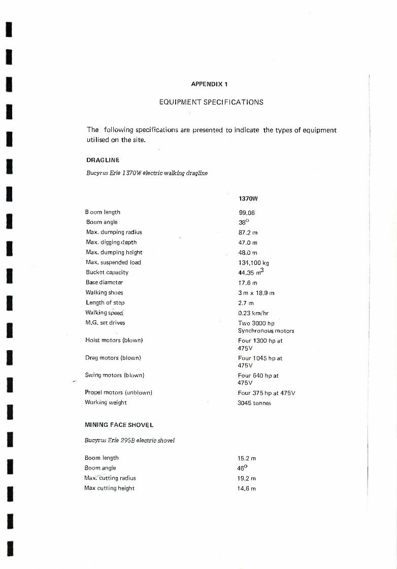
I I I 1 I I I I I I I I I 1 I I I I I I
APPENDIX 1
EQUIPMENT SPECIFICATIONS
The following specifications are presented to indicate the types of equipment
utilised on the site.
DRAGLINE
Bucyrus Erie 1370W electric walking dragline
1370W
Boom length 99.06
Boom angle 380
Max. dumping radius 87.2 m
Max. digging depth 47.0 m
Max. dumping height 48.0 m
Max. suspended load 134,100 kg
Bucket capacity 44.35 m3
Base diameter 17.6 m
Walking shoes 3m x 18.9 m
Length of step 2.7 m
Walking speed 0.23 km/hr
M.G. set drives Two 3000 hp Synchronous motors
Hoist motors (blown) Four 1300 hp at
475V
Drag motors (blown) Four 1045 hp at 475V
Swing motors (blown) Four 640 hp at 475V
Propel motors (unblown) Four 375 hp at 475V
Working weight 3045 ton nes
MINING FACE SHOVEL
Bucyrus Erie 295B electric shovel
Boom length 15.2 m
Boom angle 460
Max: cutting radius 19.2 m
Max cutting height 14.6 m

Radius of level floor at face 12.7 m
Max. dumping radius 16.2m
Max. dumping height at max. dumping radius 9.2 m
Max. digging depth below ground level 2.6 m
Bucket capacity 16.0 m3
Overall width 8.7 m
Induction motor 800 hp continuous, 2000 hp intermittent
Hoist motor (blown) One 800 hp at 475V
Swing motor (blown) Two 195 hp at 475V
Crowd motor (blown) One 195 hp at 475V
Propel motor (blown) One 375 hp at 475V
Working weight 549 tonnes
HYDRAULIC EXCAVATOR
Orenstein and Koppel (0 & K) RH 75-800
Shovel Operation Backhoe Operation
Max. cutting/dumping radius
- corresponding cutting/dumping ht
Max. cutting/dumping height
—corresponding cutting/dumping radius
Max. digging depth
Rated bucket capacity (rock type)
Engine
Horsepower (DIN 6270)
Hydraulic horsepower
-- Operating weight
10.5m 15.0m
9.8m 5.Om
10.Om 11.0m
7.4m 11.5m
2.9m 8.6m
7.6 m3 55 m3
2 x water cooled Cummins diesel engine (NTA - 855 - C)
2 x 348 hp at 2100 rpm
2 x 270 hp
129 tonnes
Orenstein and Koppel (0 & K) RH40-700
Max. cutting/dumping radius
- corresponding cutting/dumping height
Max. cutting/dumping height
- corresponding cutting/dumping radius
Max. digging depth
Rated bucket capacity (coal type)
Engine
Horsepower (DIN 70020)
Operating weight
Shovel Operation
9.Om
3.Om
8.7 m
5.9m
4.Om
6.0 m3
1 x Deutz air-cooled diesel engine (BE 12 L413)
1 x 432 hp at 2300 rpm
82 tonnes

I I I I I I I I I I I I I I I I I I I 1
FRONT-END-LOADER
Michigan 475B Wheel Type Loader
OveraU operating height
Dump height
Dumping reach
Rated bucket capacity (rock type)
Engine
Operating weight
OVERBURDEN BLAST HOLE DRILL
Bucyrus Erie 45R Rotary Drill
Drill pipe length (optional)
Blast hole diameter
Engine
Pull down force
Operating weight
COAL AND PARTING BLAST HOLE DRILL
Gardner Denver RDC 30
Drill pipe length 7.6 m (single pass)
Blast hole diameter 159mm —200mm (6Y4 in. —77/8 in.)
Engine G.M. 8V-71—N diesel
Pull down force 13,600 kg.
Operating weight 29,384 kg.
TRUCKS
(a) Haulpak 120B Electric Rear Dump
Engine
G.M. DDAD 12V-1491
Rated brake horsepower
1200 hp at 1900—rpm
Net vehicle weight
79,063 kg.
Payload
108,863 kg.
Solid volume overburden (struck)
52.7 m3
7.9m
4.1 m
1.7 m
9 m3
Cummins VTA - 1710 - C 700 diesel 680 hp max., 617 hp flywheel at 2000 rpm
70700 kg.
9.9 m - 16.7 m (single—double pass drilling)
170 mm —270 mm (6% in - 10 /8 in.)
Cummins diesel NT-855—P-380, rated 320 hp at 2000 rpm
31,818 kg.
67,727 kg.

(b) Euclid R85 Rear Dump
Engine
Gross vehicle horsepower (SAE)
Net vehicle weight
Payload
Solid volume overburden (struck)
Coal body capacity (side boards)
Cummins VTA-1710C
800 hp at 2100 rpm
51,600 kg.
77,100 kg.
39.8 m3
65 tonne
(c) Haulpak Model 50 Rear Dump
Engine
Rated brake horsepower
Net vehicle weight
Payload
Solid volume overburden (struck)
Cummins VTA-1710C
635 hp at 2100 rpm
34,174 kg.
45,360 kg.
23.55 m3
SCRAPERS
CAT 623B Elevating Scraper
Scraper bowl capacity (heaped)
Flywheel horsepower
Net weight
16.8m 3
330 kw at 1900 rpm
31,736 kg.

I
I APPENDIX 2
DRAGLINE PRODUCTION ESTIMATES
The dragline works on a three shift basis, five days a week for the first eight years
of operation and then operates seven days a week when working in the multi-
I seam situation in the East Pit.
I Shift hours per week on five days operation = 5 x 24 = 120 hours
Deduct 1/2 hour/shift for shift changeover
Allow machine availability of 80%
I Working hours/week = (120) - (15 x 1/2) x 80% = 90 hours
Working weeks/year = 46
Operating hours per year = 4140 hours
I Walking time is included in the 20% non working time.
When working on a seven day week operation, maximum operating hours per
I year were taken as 5888 hours.
The annual production for the dragline was determined by considering the
I various dragline operations and applying the corresponding output rate. Outputs
were based on a 50 minute hour. Relevant information is as follows:
Maximum suspended load ... 134,100 kg
I Bucket rating heavy duty ... 1,219 kg/rn3
Overburden bank density . . . 2,470 kg/rn3
I Overburden swell . . . 30 %
Bucket Fillability . . . 95 %
I Bucket
Bucket Factor
Capacity
. . . 0.73
.. . 44.35 m (58 yd3 )
Solid volume handled by bucket . . . 32.37 m3
I Dragline operations consist of:
I WEST PIT
North Cuts
I
Digging to Thiess seam - no rehandle.
Digging to Puxtrees seam - rehandle key cut from operation (a).
Digging to Balmoral seam by extended bench method with large rehandle
Iinvolved.
South Cuts
I Chopping to Puxtrees Seam (chopping operations above the dragline
seat level are inefficient and output is taken as 80% of similar digging
operation).
I Digging 70% of Balmoral overburden from highwall side.
Working from bench on spoils and cross-dragging remaining 30% of dig
down to Balmoral Seam including some rehandle.
I

(g) Working from spoil bench and chopping parting between Bi and B3 plus
remaining rehandle. (Take 90% of digging output).
Operation Swing Overburden Theoretical Cycles! Output Angle depth (m) cycles!hr 50 min.hr 50 mm. hr
m3/hr
900 10 77.77 64.81 2093
900 10 77.77 64.81 2093
1350 20 63.94 53.25 1720
1800 10 54.31 45.26 1165
90° 20 77.77 64.81 2093
1500 20 60.38 50.32 1623
1500 30 60.38 50.32 1460
EAST PIT
Cuts JE to 5E (70m)
Digging key cut to Balmoral and extending dragline bridge.
Sitting out on extended bench, cross-dragging and swinging round to
dump at 1500.
Cuts 6E to 1 8E (50m)
Digging from G5to T2with key cut spoils being dumped on P2 pavement
and remainder of spoil being cast over lower highwall.
Chopping parting T2 - P2. (Take 80% of digging rate).
Digging key cut to Balmoral seam and extending bridge.
Sitting on bridge and cross-dragging to form final spoil profile.
Operation Swing Overburden Theoretical Cycles! Output Angle depth (m) cycles/hr 50 min.hr 50 min.hr
m3/hr
90° 10 77.77 64.81 2093
1500 40 60.38 50.32 1623
90° 10 77.77 64.81 2093
-' 1800 10 54.31 45.26 1165
90° 20 77.77 64.81 2093
1500 40 60.38 50.32 1623
NOTE: Although the maximum operating radius of the dragline is 87.2m an
operating radius of 83m was used for the determination of Rehandle
quantities.

I I I I I I I I I I I I I I I I I I I I
APPENDIX
SHOVEL/LOADER PRODUCTION ESTIMATES
(a) Bucyrus Erie 295B electric shovel (overburden removal).
Rated bucket capacity 16.0 m3
Bucket Factor 0.6
Solid volume handled by bucket 9.60 m3
Average cycle time 30 secs.
Output per 50 mm. hour 960 m3 /hr.
Shift hours/week : 3 x 8 x 5 = 120 hours
Deduct meal breaks : start up : shut down : 3 x 1 x 5 = 15 hours
Allow 80% mechanical availability
Working hours per week = 84 hours
Output per week = 80700 m3
Working hours per 44 week year = 3696 hours
Output per 44 week year = 3,551,000 m3
0 & KRH75 hydraulic excavator (overburden, coal and partings removal).
Rated bucket capacity (rock) 7.6 m3
Bucket factor 0.61
Solid volume handled by bucket 4.64 m3
Average cycle time 30 secs.
Output per 50 mm. hour 464 m3 /hr.
Shift hours/week (overburden) : 3x 8 x 5 = 120 hours
Deduct meal breaks : start up : shut down : 3 x 1 x 5 = 15 hours
Al low 80% mechanical availability
Working hours/week = 84 hours
Output per week = 38976 m3
Working hours per 44 week year = 3696 hours
Output per 44 week year = 1,715,000 m3
When used on coal and parting removal the machine is working at an average
rate less than this estimated output.

(c) 0 & K RH40 hydraulic excavator (coal removal)
Rated bucket capacity (coal) 6.0 m3 Bucket factor 0.61
Solid volume handled by bucket 3.66 m3 Average cycle time 30 secs. Output per 50 mm. hour 366 m3 /hr
Shift hours/week : 2 x 8 x 5 = 80 hours
Deduct meal breaks : start up : shut down : 2 x 1 x 5 = 10 hours
Allow 80% mechanical availability
Working hours/week = 56 hours
Output per week = 20496 m3
Working hours per 44 week year = 2464 hours
Output per 44 week year = 902,000 m3
On coal excavation the machine is working at an average rate less than this
estimated output.
(d) Michigan 4 75B Front-End-Loader (coal and parting removal).
Rated bucket capacity (rock)
Bucket factor
Solid volume handled by bucket
Average cycle time
Output/50 mm. hour
Shift hours/week 2 x 8 x 5
Deduct meil breaks : start up : shut down : 2 x 1 x 5
Allow 75% mechanical availability
Working hours/week
Output per week
Working hours per 44 week year
Output per 44 week year
9.0 m3
0.60
5.4 m3
40 secs.
405 m3 /hour
= 80 hours
= 10 hours
= 521/2 hours
= 21,260m3
= 2310 hours
= 935,000m3

I APPENDIX 4
OVERBURDEN, COAL AND PARTING PREPARATION
Loading Pit Material Location Quantity Pattern Drilling
Ratio
('000's m3 ) (m x m) (m) m3 /kg.
NW Overburden Box Cut 1125 6 x 6 31250 2.95
Overburden Remaining 17701 7 x 7 361243 2.95
Coal Balmoral 2677 5 x 5 107080 7.60
WEST Overburden Box Cut 3080 6 x6 85554 2.95
Overburden Shovel pre-strip 3928 6 x 7 93522 2.95
Overburden G5 to T2 & T2 to P2 8641 6 x 5 288033 2.95
Overburden P2toB1 17462 7 x 8 311821 2.95
Coal B31 & B32 4711 3 x 3 523442 7.60
Partings Bi - B31 3872 3 x 4 322663 3.20
EAST Overburden All shovel Overburden 72052 6 x 7 1715521 2.95
Overburden G5 to T2 18099 6 x 7 430857 2.95
Overburden P2 to Bi 53144 7 x 8 948964 2.95
Parting T2 to P2 8937 4.5 x 4.5 441328 3.20
Parting Bi - B3 6370 3 x 4 530832 3.20
Coal B3 14234 4.5x4.5 1 702904 7.60
Put Material Average
Thickness
NW Balmoral coal 10 m
West Overburden G5 to T2 andT2toP2 8m
West Overburden P2 to B1 19 m
West Partings B1—B3 4 m
West Coal B31 and B32 2.5 m
East Overburden G5 to T2 10 m
East Overburden P2 to Bi 21 m
East Partings B1—B3 4 m
East Partings T2—P2 5 m
East Coal B3 6 m
I Li I I P I I I I I I k I I I I I I I

DRILLING ESTIMATES
Overburden Drills (Bucyrus Erie 45R drilling 229 mm dia. holes)
Annual drilling requirements were determined throughout the mine life and
drills were scheduled to operate on a sufficient number of shifts to meet these
requirements.
The drills are utilised on a five day week basis, working two or three shifts per
day.
Considering an 8 hour shift.
Allow: 1 hour for meal break, start-up and shut-down.
80% mechanical availability.
an average penetration rate of 25 metres/hour.
i.e. working hours per shift = 5.6 hours.
Working hours/week = 28 hours.
Operating on 44 weeks/year, working hours/year = 1232 hours.
Drilling achieved per week for 28 hours = 700 metres.
For a double and triple shift operation the drilling achieved per week would be
1400 m and 2100 m respectively.
Coal and Parting Drills (Gardner Denver RDC 30 drilling 159 mm dia. holes)
Coal and Parting drills are worked on a single (8 hrs) or double (16 hrs) shift
basis five days/week (i.e. 28 or 56 working hours/week).
Average penetration rates were taken as 35 metres/hour for drilling partings and
45 metres/hour for drilling coal. For a single and double shift operation in
parting drilling this gives 980 and 1960 metres/week respectively and for a
single and double shift operation in coal drilling this gives 1260 and 2520
metres/week respectively.

DARWIN
P J
N.T
WA QLD.
BRISBANE
DRAYTON COAL M I NE. PERTH N S W • Newcastle
ADELAIDE I
SYDNEY
vi'c_m• CANBERRA
MELBOURNE 0
HOBART
DISTANCES FROM IJRAYTON MINE
By road to Antiene ----------8 km.
By road to Newcastle ------ 123 km.
By rail to Newcastle ------ 11L km.
SCALE 50 0 50 100 Iii ii I
KiLometres
I I I I I I I I I I I I I I I I I I I I
Sydney Basin

Rsf.r.ncs Railways - Private
Railways - Public
Highways
Other Roads Location of Collieries
shown thus ow-t -.-o
do 0-ti -o
do
do
do GO/C, •U/G
3 0 3 6 9Km.
0 4 6Mjles
I I I I I I I I I I I I I I I I I I I I
Danga Aberdeen
Gap
Musweflbrook NO2 Extended çees______
DRAYTON MINJ
ene?
rook L F_L___I &Ifl 4
LIDDELL POWER STATION-.. ruyurou N' I
NEWDELL SIDING & tHeoaen
.ddeII wamp Cree CENTRAL WASHERY
South Maitland Mines Liddell .Q
Rescue Station - Sub Station
Howick North Ravensworth NO 2 Glennies Creek
Nundah Martindale rwell
Jerrys P
lRixs Creek
Li!9iaa
12
Dart
I MuswàIIE
weIIbrook
Bavw sater NO 2
Warkworth (1GLE
Warn b 0 NO \ NThrIL
I
Wa °
Bulga .. MT. THORLEY/'5
RAIL / TERMINAL
iiiNOL* SYSUCTIOSI
GN/
SCALE
1:300 000
DRAWN
C.C. Nov.77 C RE C KED
Source of information APPROVED
Joint Coal Board of N.SW
HIESS-SHELL DRAYTON CO-VENTURE
HUNTER VALLEY COALFIELD FIGURE 2
NORTH WEST DISTRICT DRAWING
LOCATION OF COLLI ERIES Di/l/lOG -32

A) f
7 BOUNDARY
220
ANTSTA
ISTA7
ENE
RA[L \J LOOP /
/ U
I \7
1 ---- 7 -
---- -- _ii-
H-- ---- \-----.---'
H-- -- --- -. -
----
--
7
ck
-
' 7 UDDELL - DAM1I
7;
/ LIDDELL /
/ I / POwER /
/ STJ0 / -- I ----- -
H
oE
H-- •-- --- --- -- - -- - -- - -
072•
cl
-: AM
SET\7 LNUNDATION - i--- -
(FROM I
- lOAM
I H
- - SCALE 1:10000 1SCALE 1 10000 200 0 200 COO 600 000 I—
D I I RAWING I C
MAIDAS DRAWN
CHECAED'
AROVFD
CI ADiGLTsAF
- ----------- DNHBVCADR M ---- -----REW
THIESS-SHELL DRAYTON CO-VENTURE
DRAYTON COAL MINE FIGURE 3
GENERAL ARRANGEMENT VISION
DRAWING U@ D1I1/300-24R

zt z 01 0 01 0 0! 0 01 0) A!! -
3000 I6
I 3000 06Z
\
+
-------------
OZL
wtololoMm

I I I I I I I I I I I I I I I I I I I I
- -
(_) LIJ
Oh' L.J.J
<
— 0 ow I
r1
<
a
I
O0
- (I)
L a
N
Lu
LL1
- LI) L U
1
0 Jj
' <
C
ci LI) '-'
a) -
- Nm -4
Lu
- U)
LI)
(--LJJ
0><u H OW
E a
.-
IcL
LI) C
LIJ
a
N
—J
0 -J 0 Lu
(I)
>. o a
- a) -4
/ I
Ljj
LLJ
co Ln
S KE L ETA R ROWAN FORMATION FORMATION
MAITLAND GROUP GRETA COAL MEASURES
SCALE 1:/400 Vert. THIESSSHELL DRAYTON CO-VENTURE
DRAWING DATE DRAWN
R.L. Aug.77 DRAYTON COAL MINE FIGURE 5 CHECKEDP
TYPICAL STRATIGRAPHIC SECTIONS I0/2O1
112 -

S
T HEAD
I I I I
11.20 000N
I I I I I I I I I I I I I I
1419000 N
I I
Ui' Ui CD 0 CD 0
0
MINING (N
LEASE 81
\ _ \\
\\
/ 1:5000
100 0 100 200 300 \ I I Metres
,\
SCALE
1:5000 THIESS - SHELL DRAY DRAWING I DATE
DRAWN C.C. NOV.'77
Mft DRAYTON COAL
/ CHECKED PLAN OF N.W. PIT
/ ' /
APPROVED AT END OF YEAR

I I I I I I
I I
/
\\
* LU
cr
Lr I
I L I I I I I I
+
LU
292 000
----------------
I I
Tii+iiiII+
I 100 0 100 200 300 400 500
Met res
THIESS-SHELL DRAYTON CO-VENTURE
77 DRAYTON COAL MINE FIGURE 7 MIME DEVELOPMENT PLAN
01/1/501-5 p

/
I I
LU
oell
:
MNg
- 8 M
C u
os
Ll
K
2W
215
el
V 01
220
— - 2E
N
THIESS-SHELL DRAYTON CO-VENTURE DRAWNG DATE
DRAYTON COAL MINE FIGURE 8 100 0 100 200 300 00 500
EA Metres OPENCUT MINING PLAN
W/i/5013 R

- - - - - - - - - - - - - - - - - - - - :
t ..
J&.
777777777
JI
(I
It
84
111/
IV
Ox ½ WEST PIT FI

- - - - - - - - - - - - - - - - - - - IN
Ali
04
40
;
PT
Am 01,
q
o kill
: U
41
1'
/ ft IN
4 - / /
4r.\ ' •
EAST PIT FIG 10

Ln
OE
07
220
oe
I /
/80
/
60 o (1/1
J77
08' Jo292
0 /30
ob co
(7
/
7 /
(°° c
20
291 000 E SS
220
H / 129OOIE
\ 0200
THIESS-SHELL DRAYTON CO-VENTURE
1000 100 200 300 400 500 DRAYTON COAL MINE
Metres °
RESTORATION PLAN J501-6 R

E E' 300 - JJ 8089 BC61 8088 9020 Bl70 BC HV32 - 300
w - z BRGHAM
250 - - 2t
200 - _
2E
200
E
150
J
THIESS
ii
z 91 Z
- 100
F F' 300 - TM BC 56 BC 54 JT 2W JT3E 8921 JU5W JU3W
300
EES
THIESS
250 —
\\\ L7 Pi
6 — 250
it
ISO-
LLJ
-
100 - lao
LEGEND
lnfoor.d foolt h0wflg drootor, of threw
JT3E EopLotory drill hole
Wookng proIIe of trp Oot
I THIESS-SHELL DRAYTON CO-VENTURE 20 0 2040 60 80
I .1i r- CC OCT 77 DRAYTON COAL MINE FIGURE 12
Metres r00r0 EAST PIT
CROSS SECTIONS E-E F-F O1F1201-l21

BC 72 BC 65
H
LLJ
300
250-
0
--
250— -
B3-
50 -
LU LU 0
P
H' 0
5053 BCSO /03 U) > U)
-250
—250
- ISO
100
0
a U LU
In LU LU I—U z
G
'T BCS2
250 -
200 -
150
150
BOOS 82.62 BOBS BC55 BP9O 02.50 505/ 70
- 250
/ -50
150
LEGEND
r0.,0 f,ll ,60O.0J dlrolO0 ol
E oroIOry dIl 6010
Wolloog prohIe 0/ SlOp Of
1 1 I
ORATTS J DRAYTON COAL MINE
THIESS- SHELL DRAY TON 00-VENTURE 20 0 20 2.0 60 80
I FG&J 13 .
WEST PIT I I I I J
Met/es I CROSS SECTIONS 0- G H-H 01/11201- 122

DRAYTON COAL MINE ELEMENTS OF QUALITY CONTROL
Determine reserves and
Determine quality of exposed quality of coal. ca a I Infill drilling to improve the
Basis for reliable estimates of
uccuracy of previous data. daily production quality.
DIRTY COAL
LOW ASH COAL HIGH ASH COAL
STOCKPILE
STOCKPILE JIG
WASH IN 0 FL ANT
" To remove any Analysis of samples large hard rock taken during the lumps from the various coal handling!
I
raw coal, treatment operatioris
Q. A dual line system to To remove shale and other
Lu handle fluctuations in impurities from the coal.
I c- run-of-mine coal feed Routine samples taken to ' without affecting in-pit monitor performance of the
mining operations. washing process.
To monitor the crushed coal To monitor the feed rate to production rate. J [jig plant.
To provide raw coal samples for laboratory analysis-the results used to control washing and blending requirements.
I
, OVERLAND
t STOCKPILE AT L OADING PORT
I
To allow additional blending of coal as required.
[To monitor tonneage and loading rate
1, L
CL) . TRAIN LOAD IN
I
To monitor reclaim rate and to control automatic sampler
To allow for the selective blending of differing coal qualities.
To monitor the quality of coal being railed.
To monitor coal output from jig plant
CONVEYOR
SHIPMENT TO OVERSEAS CUSTOMERS
ORAl OUR \
To determine quantity loaded into ship Certificate for commercial transactions.
Determine quality of loaded product to a predetermined precision for commercial transaction purposes 1: - OF 14 results certified by independant analysis.
IruIlI;I;o III
STACKING & RE CLAIMI NO
wFIi

5-
/
)
\k \\
/ \
Z / I NATUL \ VEGETATWN
1PAH o o /_J V)
/ DIRTY CO L
ON
NAURAL VEGEATION
/
/ LCAR IAHK
PLA
\ \SF UR ITY \\/
]
C C V C NC
I C RE ENI NC
"S I
CAR ITA 11 1 CAK J JASTAFF L SAYICN
/
CYCLONE
- P A NT 11 KY SUB
O SIORFS DELIVERY STATI9' THICKENER
\ WITCHYARD
LLJ
STORE ROTARY N BRFAKER S // VEBL
cCNV /
N - - - ODVERED SCHEENINT
STORAG
COMPOUND ROTARY
--LIGHT VEHICLE /AICE,' BREAKE
WASH HEAVY
DU
URNING
ROAD
SCALE 1:2000 THIESS-SHELLDRAYTON CO-VENTURE
\\ / DRANG DATE
—Drcincq A / HECKEfl
/Y 2/7V P1 T HEAD REVISION
Perrncinont jrve Mr
/
(10/ S '5UATFG 0 DAM , ESTABLISHMENT DRAWING No
/30022R

IS
IS
4
CONVEYOP BFir LA'E Br,
cL
A —
tVST/NG rn4DwAy I (N £AtL.4P
HIGHWAY) N47AL
PART ELEVATION
OVERLAND CONVEYOR
S
SECTION A - A. SECTION B - B
TYPICAL TRESTLE DESIGN
D1/1/30013 III It 4PA
________ S I S F I I I I
FIGURE 16 —SHELL DRAY1ON CO-VENTURE I MINE PROJECT
AND BRID JCOUT*ACT muffilpowl
IQ2O1-04 1 Iti. I1** lfJHleI Itt LItt 5 5

A ..44- FLOOQ L 14G,000
PLAN VIEW
-7 Ll yT
1LJ
SECTION AA
FIGURE 17 c i. I4o.uiJ THIESS.-SHELL DRAYTON CO-VENTt
—tU i200U0J I COAL MINE PROJECT
II T Lfl
ro2ri--(75
STATKN
27 7 Ut
1 I I . I I I I I
I I
1 I I I I I I I
H -- r /
floe ropaat / TO)
so cy
*JM t.Ot'T744 4TAT7ON
.1IR.2
'
ATrn.lL
j --
TO /
I
-
-
I ftoposc. ROAD 10 APJTII}Jt 9T&flOW
7 7
L j LOCATION PLAN ANTIENE RAIL LOOP
SCALE 1 5000
t. %t.oO
.J.V RL 140
ELEVATION CONVEYOR TL1. SCALE 1:1000
ELEVATION
IJ t.ALL. Le\/L5 lF. M1E.S. t.AIL DI JSI4S %PJ MILLU4LTg UQp..
01/1/305-11
t'.jeO,AarIc C."-. - '-aE-ra,ttSts.t cul.nt
0 CTJTE '1'TO7
.LlILL__ _
— --------
ENLARGED DETAIL AUTO LOADING CHUTE SCALE 1:50
T.O.S.
P',)LLY
L i1,15O T.cl. .
SL I1,G TOO r02 OF TO714
4
$
*
m
L
QL. TOP OP RAIL
raL ¶RTO, eoo
0.L 1TOR,WO %XISTIVIa
I

'' ii. AThornton A
_ /
j ..-.-- Ino
Beresfi
Tarro
Hexham
(/
-WILLiamtown
' I,
KOORAGANG
ISLAND
I
I
I
I
F
I
LI
LI
I
I Sandgatet --
/
%'O ChanneL
4E \ 4jj B>
yfietd p
/
You ngWa EL send
B adow
/
MAIN Cardiff
000
Cockle Ck.
I
otL -
I
CharLeslown
0 / V
V-33
/ MACQUA RIE
V Ship Turn i ng Basin
New Port Waratah Coal Loaderj[,~to~.kton—_
nrl
Coal Storage -- Roads err
I
I Ratiways
/S.B. Carnngton Basin
Coal Loader
Adamstn "(erewether
SCALE
Mites I____________________
10 1 2 3 1 - Kilo metres i I I I I I
SCALE
THIESS-SHELL DRAYTON CO-VENTURE AWING DATE
fNR Ve f Dec.'77 F'4EWCASTLE HARBOUR LOCATION PLAN FIGURE 18
KEDk D5 Dec- T? SHOWING COAL STORAGE AND DRAWINGNO.
OVED PORT FACILITIES J D1111803-6
I
I
I
I
I
I
I
I
I
LI

CC1O
SURGE BIN
I1 fc15A
STACK No-2
C 7 C 18
STACK No.3 I
C 12 RECL AIM
C13 STACKING
SURGE BIN I
19 1 JJ C21I
20 LtJ T BINI BIN2
CARRINGTON BASIN BERTH I
OC 6_ 7fJ. CC 9
TOWER TOWER 16 17
010 ol 01 001
1j-- T0'' 14
TC5 TOWER T5 TC8H I. i. TC8
R 13
TCS
T4A [1.-I] RC1O
SC6AISC7A
r i OH. 2
\ u
ROAD RECEIVAL DUMP HOPPERS (8 x 260 TON NE)
SURGE
V STACK No.4
THIESS-SHELL DRAYTON CO-VENTURE
SCHEMATIC LAYOUT OF FIGURE 19
PORT OF NEWCASTLE DRAWING No.
COAL LOADING FAC ILITI ES 01/1/803 -12
4
4
4 U
Lii —J Lii
rL O 0 I— (I).
a.
C) 0 Li)
SCALE
DIRECT TRUCK LOADING FROM WC1 & WC2.
PORT WARATAH BERTH
Ll
- WC3
SURGE BIN SB.2
DIRECT TRUCK LOADING FROM SB.3
SPILLAGE BIN SB.3
BASIN TRACK
00
HOPPERS 00
TOWER T2 TOWER TI
IC 2 -
TC3 j TC4
TC1O Ici
IC) U U
D R I V E 1
T
HOUSE DH.1 4
Of
BIN SB.1 l Ll -,1
Ic SR , F1B ft WR(i))R2 I () w
h/)
ul to O--'- c 1c 4 \
I co
I
<I 4
R M
1 RM
2
a:: CA 4 4
;V
Ui -J Lii -J EI
RAIL RECEIVAL HOPPERS RH1

STAGE 1
( I Remove overburden above P2
by shovel & truck.
I b) Drill and blast overburden P2 to Bi.
(c) Level blasted overburden with dozer.
(dl Dig key cut and cast to form
extended working bench for dragline.
STAGE 2
(e ) Move dragline to position 2, cross cli y
from key cut and cost to form final
spoil profile.
(f) Remove Balmorat coal and partings
by shovel & truck.
Highwall Angle 630
Spoil Angle 360
Swell Factor 30%
Cut Width 70 m.
Rehondle 22%
I I I I I I
I I I I I I I I I I I I
tt of D/L.
tof OIL.
DUMPING RADIUS 83m.

I I I I I I I I I I I I I I I I I I I I
G5
(a) Remove overburden above 05 12 by shovel & truck.
P2 (b) Drill and blast overburden
05 to T2.
(c) Drill and blast overburden P2 toBi.
Bi Id) Dragline in position 1 dig
B3 key cut and dump spoil over edge of upper highwalt.
clof O/L.
© DUMPING RADIUS 83m.
STAGE 2 rTM7M77 G5
(e) Move dragline to position 2
/ZY T2 dig remaining overburden and
1 P2 rehandle and dump spoil over ..................... lower highwall.
/ (f) Remove T2 coal.
/ (g) Drill and blast T2 to P2 parting.
I
Highwall Angle 63
Spoil AngIe 36
Swell Factor 30% [SCALE
Cut Width 50 m 1:1000 THIESS-SHELL DRAYTON CO-VENTURE
_______________________________________________________________________________________________

Highwall Angle 63
Spoil Angle 36
Swell Factor 30%
Cut Width 50 m.
Rehandle 46%
I I I I I
I I I I
Varying C of D/L.
©
DUMPING RADIUS 83m.
05
T2
P2 STAGE 3
I h ) Chop parting T2 to P2 and cast to extend dragline bridge.
i ) Dig key cut from P2 toBi Bi and cast spoil to extend
B3 bridge out from highwall.
I
DUMPING LIMIT 83m.
05 STAGE 1+
(j) Extend dragline bridge
T2 with spoil from P2 to B.
P2 1k) Move dragline to position L., crossdrag from key cut and cast to form final spoil profile.
(1) Remove P2 coal and Bi Balmoral coal and partings
B3 by shovel & truck.
I I I I I I I I I
I
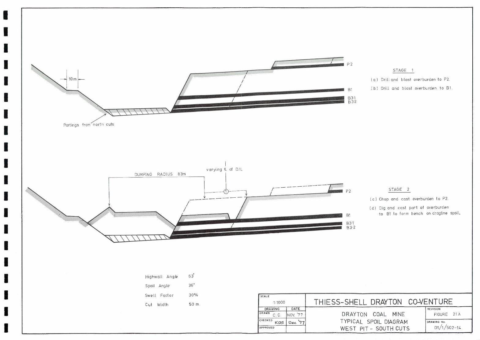
P2
STAGE 1
(a) Drill and blast overburden to P2.
b) Drill and blast overburden to Bi.
B 3-1 B3-2
P2 STAGE 2
Chop and cast overburden to P2.
Dig and cast part of overburden
to BI to form bench on dragline spoil.
B3-1 B 3-2
I I I I I I I I I I I I I I I I I I I I
Partings from-~~h cuts
varying of OIL
Highwall Angle 63
Spoil Angle 36
Swell Factor 30%
Cut Width 50 m.

STAGE 3 P2
(e) Deadhead Dragline along spoil
bench to central access Ramp.
( f ) Cross-drag and cast remaining Bi overburden exposing Bi coat.
B3-2 I g I Remove Bi coat by shovel&truck.
C h) Drill and blast Bi to B3 1 Partings.
P2 STAGE 4
Ci) Deadhead Dragline along spoil
bench to central access Ramp.
Bi Ci) Chop and cast parting above B31.
Dig and cast1 rehandle spoil to
B3-2 form final spoil profile.
(k) Remove remaining coal and partings
by shovel & truck.
Highwalt Angle 63
Spoil Angle 36
Swell Factor 30%
Cut Width 50 M.
Rehandle

I I I I I I I I I I I I I I I I I I I I
Tender SCALE
Order/.5upP/y/Contruct THIESS-SHELL DRAYTON CO-VENTURE DRAWING DATE WN
"/ 7 / 78 DEVELOPMENT FIG. 22 CHECKED - SCHEDULE SUMMARY
DRAWING No
APPROVED Di / 1 01 15
1918 1313 1380 1381 138 1983 1384
Apr-June luly - Sep Oct-Dec Jan - Nr pr -June July 5ep Oct-Dec Ian -June July - Dec Jan-June July-Dec )an-Jun }Dec y Jan June lu& -Dec Jan iune J -Dec
Fina/5e Lease/Conditions
Obtain N/n/n9 Purposes Lea.se
Development A pp//cat, on,14ppro'
Joith Coal Board Approval Enviromental Impact s tatement Trading E Board Decisions DEVELOPMENT Design Spec5.
CON5 TRUCT 51te Service 5
Power Offices VVOr.k5/io,b etc. 5ur face C/v//s
Coal Cru.thing Screening
Coal S facl< my & Reclairning
O/L Conveyor & Rail Loop
Overburden DrilLs Hydraulic Exc.avator5 76n Hydraulic EXC.avator5 4-5m
3
Dump Trucks Dozers/Grader3 Coal Drill Electric. 3hove/
PRODL/c TION Overburden Excavation
Coal Product/on
3 4 5
— — —
— —
Water
MAJOR PLANT
— — — — —
— — —
— —
— -----
— — — — --
Coo'! Preparation Plant
— —
Draglie
— — —. ---
-- — — —
— —
Bib
