egt...exhaust gas temperature (egt) sensor connections warning when installing the egt sensor, wear...
TRANSCRIPT

Installation Guide
EXPANDABLE ACCESSORY SYSTEM
EGT

Table of Contents4 Read Me4 Important Information4 Safety Terms
5 At a Glance5 EAS (Expandable Accessory System)
6 Main Cable Connections6 Securing the EAS7 Routing the Main EAS Cable7 Connecting EAS Accessories
8 JAB (Juice Attitude Bridge)8 Juice to Attitude Connections
9 EGT (Exhaust Gas Temperature)9 Exhaust Gas Temperature (EGT) Sensor Connections11 Non-Expandable EGT
12 SOTF (Shift On The Fly)12 2011-2014 Ford 6.7L13 2015-2017 Ford 6.7L14 2010-2018 Dodge/Ram 6.7L15 2001-2004 GM 6.6L LB716 2004.5-2005 GM 6.6L LLY17 2006-2007 GM 6.6L LBZ18 2007.5-2010 GM LMM19 2011-2016 GM 6.6L LML
20 Universal Sensor Input20 Applications20 Drilling and Tapping21 Temperature Sensor Installation22 Pressure Sensor Installation23 Generic Sensor Installation
24 Turbo Cool Down24 Fuse Box Locations24 Installing the Fuse Adapter26 Generic Installations27 Dodge Adapter Installation

28 Power Switch28 Connections29 Monitoring Tools with Power Switch - Device 131 Monitoring Tools with Power Switch - Device 232 Monitoring Tools with Power Switch - Device 3
33 EAS 12V Power33 Connecting to Power
34 MyStyle34 Starting MyStyle35 Universal Sensor Input - Explained36 Universal Sensor Input - Custom Mapping38 EGT Sensor38 Display Setup39 Power Switch

4 Read Me
Important InformationRead Me
Safety Terms
Before using your new EAS device, it is important that you update your product. Refer to the Display Device’s User Guide for more information on how to use the Fusion update software, or visit our web site.
Please take the time to thoroughly review all of the information outlined in this guide. Taking the time to understand how this product works and how to properly operate it will ensure that you have an extraordinary and safe driving experience. If we can be of any assistance to help you get the most from your product please call us.
Thank you again for your business and enjoy your new product. IMPORTANT: Read through these instructions completely so that you understand each step prior to installation. Refer to the Display Device User Manual for Safety and Warranty info.
Throughout this guide (hereafter noted as User Manual or Manual) you will see important messages regarding your safety or the protection of your vehicle. These messages are designated by the words WARNING or CAUTION.
WARNING indicates a condition that may cause serious injury or death to you, your passengers or others nearby. Pay careful attention to these Warning messages, and always comply with them. They could save a life.
CAUTION indicates a condition that could cause damage to your vehicle. It is important to install and operate your prod-uct in conformance with instructions in this Manual. Caution alerts you to particularly important things that will keep your vehicle operating properly.

5At a Glance
At a GlanceEAS (Expandable Accessory System)
JAB Adapter The Juice to Attitude Bridge allows you to connect your Edge Juice Module to your Attitude Moni-tor.
Turbo TimerThis accessory keeps the engine running, when the vehicle has been parked, and allows the engine to properly cool down before it is shut off.
Power SwitchThis accessory gives you
the ability to control two separate devices using
your Display.
SOTF The Shift On The Fly gives you the ability to change lev-els in place of a DSP switch.
Main EAS Cable
Connects the EAS accesso-
ries to the main device cable
End CapUsed to terminate the communication lines.
EGT Probe- Exhaust Gas Temperature probe can be used to monitor engine tem-
peratures during nor-mal and extreme
driving condi-tions.
Universal (5V) Sensor This accessory gives you the ability to monitor a
variety of sensor output readings using
your display.
NOTE: The HDMI to OBDII cable is included with your display device (i.e Insight, Evolution, or Attitude). Please refer to the display’s installation guide for more information on how and where to install it.
The EAS system was designed with ease of installation in mind. The system itself is installed under the hood with only one cable that has to be routed through the firewall.

Main Cable Connections6
Main Cable ConnectionsSecuring the EAS
Overhang
STEP 1 - Using the supplied zip ties, fasten the EAS connectors underneath the overhang which runs across the top of the fire wall. Keep the EAS assembly close to the driver side.
STEP 2 - Use any remaining zip ties to secure loose cable. NOTE: If more than one EAS device is plugged together, use the long zip ties provided in the packet to connect their bodies together.
Zip Ties
Endcap must always be connected

Main Cable Connections 7
Routing the Main EAS Cable
Connecting EAS AccessoriesThe round EAS connectors are Keyed which means that they can only be plugged in one way.
STEP 1 - Locate the two “key” features on each connector and lightly push the two together. CAUTION: Be carefull not to damage the gold contacts during installation.
STEP 2 - While lightly pushing the two connectors together, twist the nut until you feel the tabs snap/lock into place.
HDMI to OBDIICable
STEP 1 - Locate an entry point from underneath the hood and into the cab.
TIP - Most vehicles will have a rubber or plastic plug that can be removed from the firewall. Other vehicles may already have cables or wire harnesses going through it. STEP 2 - Route the rectangular (6 pin) connector from underneath the hood and into the cab. Leave the round connector under the hood.
CAUTION: Be careful not to damage the connector and/or it’s locking mechanism during installation. STEP 3 - Plug the Main EAS Cable into the HDMI cable junction.
STEP 4 - Make sure this junction is free from moving vehicle components (e.g. brake pedal, gas pedal, steering column, etc)
Nut
Tabs Tab SlotsGold Contacts
Keyways Keys
8 JAB (Juice Attitude Bridge)
Juice to Attitude Connections
JAB (Juice Attitude Bridge)
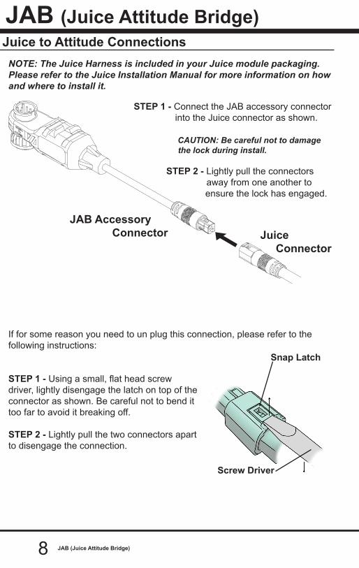
NOTE: The Juice Harness is included in your Juice module packaging. Please refer to the Juice Installation Manual for more information on how and where to install it.
STEP 1 - Connect the JAB accessory connector into the Juice connector as shown.
CAUTION: Be careful not to damage the lock during install.
STEP 2 - Lightly pull the connectors away from one another to
ensure the lock has engaged.
If for some reason you need to un plug this connection, please refer to the following instructions:
STEP 1 - Using a small, flat head screw driver, lightly disengage the latch on top of the connector as shown. Be careful not to bend it too far to avoid it breaking off.
STEP 2 - Lightly pull the two connectors apart to disengage the connection.
Snap Latch
Screw Driver
JAB Accessory Connector Juice
Connector

9EGT (Exhaust Manifold Temperature)
Exhaust Gas Temperature (EGT) Sensor Connections WARNING When installing the EGT sensor, wear eye protection and protec-
tive clothing to protect from getting metal chips in your eyes and skin. Also, since exhaust manifolds can be very hot, allow the engine to cool before drilling. When working under the vehicle, make sure the parking brake is set. CAUTION: One effective way to avoid metal fragment contamination in your engine manifold is to apply grease in the tip of the drill bit and threads of your tap tool when drilling/tapping the hole in your manifold. Reduce pressure on the drill when the drill breaks through the manifold wall to reduce risk of pushing metal chips into the manifold.
EGT (Exhaust Gas Temperature)
STEP 1 - Drill a 21/64” (5/16” optional) hole through the exhaust manifold wall.
STEP 2 - Use a 1/8” National Pipe Tap (NPT) to cut threads into the hole drilled in STEP 1.
STEP 3 - Remove the fitting from the thermocouple end and install by the tapered thread end into the manifold. Tighten the fitting so that it is securely seated.
NOTE: Ideally the bottom of the fitting would be less than or flush with the inside of the manifold wall.
Required Tools - Drill- 1/8” drill bit (pilot hole)- 21/64” (best size) or 5/16” drill bit- 9/16” wrench or socket- 5/8” open end wrench- 1/8”-27 NPT Thread Tap- Phillips screwdriver- 5/16” or 8mm wrench
ThermocoupleProbe
Fitting
Exhaust Manifold Wall
Tapped Hole

10 EGT (Exhaust Manifold Temperature)
STEP 4 - Next, insert the thermocouple through the fitting and into the center of the manifold. Be carefull not to damage the thermocouple tip.
STEP 5 - Tighten the top nut of the fitting just enough to keep the probe firmly mounted.
STEP 6 - Position the cable to allow for the least amount of bending when routing to the firewall.
NOTE: The probe will move approximately 90 Deg. clockwise in the direction the nut is tightened.
STEP 7 - Before fully tightening the nut, make sure the cable starts 90 Degrees from the final resting position.
STEP 8 - Tighten the nut until snug and until the cable is in its final resting position.
CAUTION: Do not bend the probe after installed. If needed, loosen the probe nut, adjust the probe, and re-tighten. Bending the probe tubing will result in a faulty probe.
Starting Position
Tightened Position90 Deg.
To fire wall
FittingNut
Thermocouple
Exhaust Manifold

11EGT (Exhaust Manifold Temperature) 11
The non-expandable accessory system (Standard EGT Probe) provides a single sensor allowing the user to monitor only one EGT parameter. NOTE: The EGT sensor can not be chained and if you wish to add expandable capability, you will need to purchase a new expandable EGT.
Probe
Main Cable
Non-Expandable EGT
SOTF (Shift On The Fly)12
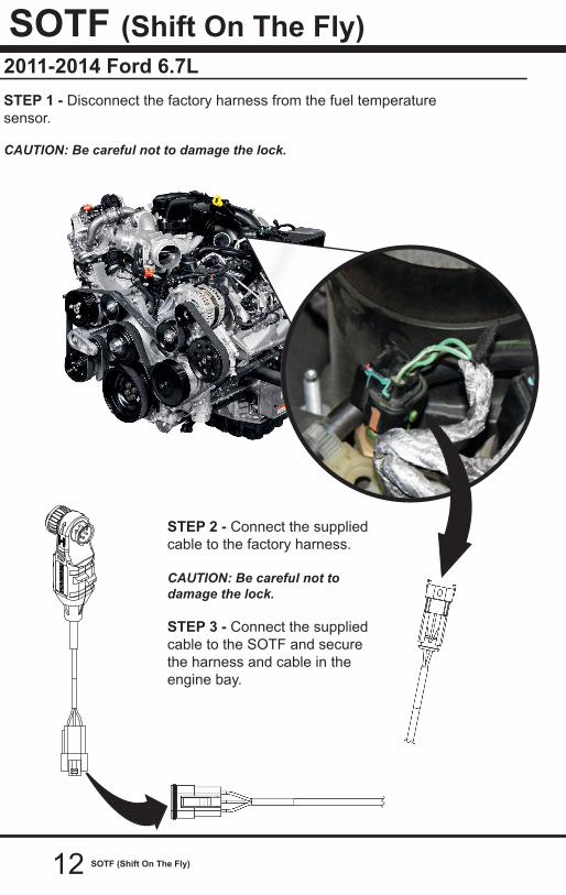
2011-2014 Ford 6.7L
SOTF (Shift On The Fly)
STEP 1 - Disconnect the factory harness from the fuel temperature sensor.
CAUTION: Be careful not to damage the lock.
STEP 2 - Connect the supplied cable to the factory harness.
CAUTION: Be careful not to damage the lock.
STEP 3 - Connect the supplied cable to the SOTF and secure the harness and cable in the engine bay.

SOTF (Shift On The Fly) 13
2015-2017 Ford 6.7LSTEP 1 - Disconnect the factory harness from the fuel temperature sensor.
CAUTION: Be careful not to damage the lock.
STEP 2 - Connect the supplied cable to the factory harness.
CAUTION: Be careful not to damage the lock.
STEP 3 - Connect the supplied cable to the SOTF and secure the harness and cable in the engine bay.

SOTF (Shift On The Fly)14
2010-2018 Dodge/Ram 6.7LSTEP 1 - Disconnect the factory harness from the crankcase pres-sure sensor. First slide the red locking tab back, before pressing the release tab and pulling the connector off.
CAUTION: Be careful not to damage the lock.
STEP 2 - Connect the supplied cable to the factory harness. Engage the lock by sliding the red locking tab in after sliding the connectors together.
CAUTION: Be careful not to damage the lock.
STEP 3 - Connect the supplied cable to the SOTF and secure the harness and cable in the engine bay.
SOTF (Shift On The Fly) 15
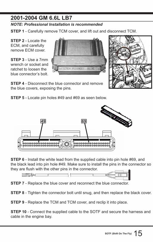
2001-2004 GM 6.6L LB7NOTE: Professional Installation is recommended STEP 1 - Carefully remove TCM cover, and lift out and disconnect TCM.
STEP 2 - Locate the ECM, and carefully remove ECM cover.
STEP 3 - Use a 7mm wrench or socket and ratchet to loosen the blue connector’s bolt.
STEP 4 - Disconnect the blue connector and remove the blue covers, exposing the pins.
STEP 5 - Locate pin holes #49 and #69 as seen below.
STEP 6 - Install the white lead from the supplied cable into pin hole #69, and the black lead into pin hole #49. Make sure to install the pins in the connector so they are flush with the other pins in the connector.
STEP 7 - Replace the blue cover and reconnect the blue connector.
STEP 8 - Tighten the connector bolt until snug, and then replace the black cover.
STEP 9 - Replace the TCM and TCM cover, and reclip it into place.
STEP 10 - Connect the supplied cable to the SOTF and secure the harness and cable in the engine bay.
49 69

16 SOTF (Shift On The Fly)
2004.5-2005 GM 6.6L LLYNOTE: Professional Installation is recommended STEP 1 - Locate ECM near the front of the engine bay, next to the battery.
STEP 2 - Lift the grey lever on the grey con-nector (J3) and detach the plug. (Push in the tab to allow the lever to slide up).
STEP 3 - Remove the black cover from the connector to expose the wire input side of the connector.
STEP 4 - Remove the green pin lock using long nose pliers, being careful not to damage or misplace it.
STEP 5 - Locate pin holes #32 and #50, and using long nose pliers carefully remove the filler pins.
STEP 6 - Install the white lead from the supplied cable into pin hole #32, and the black lead into pin hole #50. Make sure to install the pins in the connector so they are flush with the other pins in the connector.
STEP 7 - Reinstall the green pin lock and make sure the orange grommet inside the connector is still in place. Replace the black cover.
STEP 8 - Reconnect the grey connector, and ensure the lever is closed com-pletely.
NOTE: If the lever will not close, disconnect the connector and clean any dirt or debris and try again.
STEP 9 - Connect the supplied cable to the SOTF and secure the harness and-cable in the engine bay.
32 50

17SOTF (Shift On The Fly)
2006-2007 GM 6.6L LBZNOTE: Professional Installation is recommended
STEP 1 - Locate ECM near the front of the engine bay.
STEP 2 - Lift the black lever on the smaller connector until the connector is released from the ECM, then do the same for the larger connector.
STEP 3 - Remove the black cover on the larger connector by using a thin flat head screw-driver to dislodge the contain-ing tabs.
STEP 4 - Remove the pink pin lock from the connecor using a flat head screwdriver, being careful not to damage or misplace it.
STEP 5 - Locate pin holes #46 and #54; and install the white lead from the supplied cable into pin hole #46, and the black lead into pin hole #54. Make sure to install the pins in the connector so they are flush with the other pins in the connector.
STEP 6 - Carefully reinstall the pink pin lock into the connector.
STEP 7 - Replace the larger connector onto the ECM and gently push the con-nector into place, and close the lever until it closes against the ECM. Do the same with the smaller connector until both connectors are replaced.
NOTE: If the lever will not close, disconnect the connector and clean any dirt or debris and try again.
STEP 8 - Connect the supplied cable to the SOTF and secure the harness and-cable in the engine bay.
46
5452

18 SOTF (Shift On The Fly)
2007.5-2010 GM 6.6L LMMNOTE: Professional Installation is recommended
STEP 1 - Locate ECM near the front of the engine bay.
STEP 2 - Lift the black lever on the smaller connector until the connector is released from the ECM, then do the same for the larger connector.
STEP 3 - Remove the black cover on the larger connector by using a thin flat head screw-driver to dislodge the contain-ing tabs.
STEP 4 - Remove the pink pin lock from the connecor using a flat head screwdriver, being careful not to damage or misplace it.
STEP 5 - Locate pin holes #46 and #54; and install the white lead from the supplied cable into pin hole #46, and the black lead into pin hole #54. Make sure to install the pins in the connector so they are flush with the other pins in the connector.
STEP 6 - Carefully reinstall the pink pin lock into the connector.
STEP 7 - Replace the larger connector onto the ECM and gently push the con-nector into place, and close the lever until it closes against the ECM. Do the same with the smaller connector until both connectors are replaced.
NOTE: If the lever will not close, disconnect the connector and clean any dirt or debris and try again.
STEP 8 - Connect the supplied cable to the SOTF and secure the harness and-cable in the engine bay.
46
5452
19SOTF (Shift On The Fly)
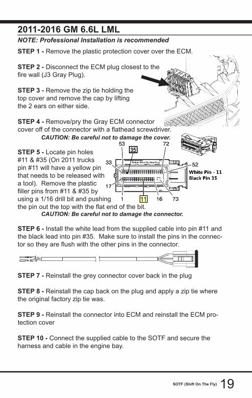
2011-2016 GM 6.6L LMLNOTE: Professional Installation is recommended STEP 1 - Remove the plastic protection cover over the ECM.
STEP 2 - Disconnect the ECM plug closest to thefire wall (J3 Gray Plug).
STEP 3 - Remove the zip tie holding thetop cover and remove the cap by lifting the 2 ears on either side.
STEP 4 - Remove/pry the Gray ECM connectorcover off of the connector with a flathead screwdriver. CAUTION: Be careful not to damage the cover.
STEP 5 - Locate pin holes #11 & #35 (On 2011 trucks pin #11 will have a yellow pin that needs to be released witha tool). Remove the plastic filler pins from #11 & #35 by using a 1/16 drill bit and pushing the pin out the top with the flat end of the bit. CAUTION: Be careful not to damage the connector.
STEP 6 - Install the white lead from the supplied cable into pin #11 and the black lead into pin #35. Make sure to install the pins in the connec-tor so they are flush with the other pins in the connector.
STEP 7 - Reinstall the grey connector cover back in the plug
STEP 8 - Reinstall the cap back on the plug and apply a zip tie where the original factory zip tie was.
STEP 9 - Reinstall the connector into ECM and reinstall the ECM pro-tection cover
STEP 10 - Connect the supplied cable to the SOTF and secure the harness and cable in the engine bay.
11

20 Universal Sensor Input
Applications
Universal Sensor Input
Drilling and TappingThese drilling and tapping instructions are generic for any install. However, you may need different drill bit sizes or additional tools for sensors we do not offer. REQUIRED TOOLS: -Drill -1/8”-27 NPT Thread Tap -Thread Sealing Compound -21/64” Drill bit -3/8” socket/wrench (temp sensor) -1/2” socket/wrench (temp sensor) -13mm Drill bit (pressure sensor) STEP 1 - Find the best location for the sensor to reside. The wall thickness of the object you are drilling needs to be able to properly capture the sensor’s threads.
NOTE: The example shows the temperature sensor being installed to the side plate of a manual transmission. This location is ideal for this particular install because the plate can easily be removed, modified, and reinstalled.
STEP 2 - Use the 21/64” drill bit to drill a hole perpendicular to the face you are drilling into.
STEP 3 - Tap the hole using the 1/8” NPT pipe tap.
STEP 4 - Clean the area in and around the tapped hole and make sure it is free of burrs and metal fragments.
SENSOR
COVER PLATE
This accessory allows you to connect up to two sensors at one time. However, if an additional accessory is purchased, you can “Daisy Chain” them to read multiple sensors at once.
The two most common sensors are temperature sensors (i.e thermistors) and pressure sensors. We offer these two types in easy to install kits that are described in the following three sections. Other types of sensors may also be connected using the 8 ft long adapters supplied with each Universal Sensor Kit. How these adapters are used will be explained in more detail later in the Universal Sensor Installation section.

21Universal Sensor Input
If you have purchased our Temperature Sensor kit, please follow these instruc-tions:
STEP 1 - Use the 1/2” wrench to tighten until snug. Do not over tighten to avoid stripping out threads.
STEP 2 - Locate the Temperature Adapter Harness included with the sensor.
STEP 3 - Remove the hardware from the end of the mounted sensor.
STEP 4 - Re-install the hardware, including the adapter’s ring terminal, in the order shown below.
STEP 5 - Tighten the nut using the 3/8” wrench or socket (Do not over tighten).
STEP 6 - Route the remaining connector and wire to the Universal Sensor ac-cessory.
STEP 7 - Plug the adapter connector into one of the accessory connectors.
Temperature Sensor Installation
COMPOSITEWASHER
METAL WASHER
LOCK WASHER
NUT
SENSORBODY
An additional temperature or pressure sensor could be used here
Temperature SensorAdapter Harness
EAS Universal Sensor Input
22 Universal Sensor Input
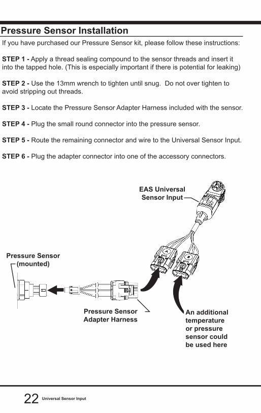
Pressure Sensor InstallationIf you have purchased our Pressure Sensor kit, please follow these instructions:
STEP 1 - Apply a thread sealing compound to the sensor threads and insert it into the tapped hole. (This is especially important if there is potential for leaking)
STEP 2 - Use the 13mm wrench to tighten until snug. Do not over tighten to avoid stripping out threads.
STEP 3 - Locate the Pressure Sensor Adapter Harness included with the sensor.
STEP 4 - Plug the small round connector into the pressure sensor.
STEP 5 - Route the remaining connector and wire to the Universal Sensor Input.
STEP 6 - Plug the adapter connector into one of the accessory connectors.
An additional temperature or pressure sensor could be used here
Pressure SensorAdapter Harness
EAS Universal Sensor Input
Pressure Sensor(mounted)
Generic Sensor
23Universal Sensor Input
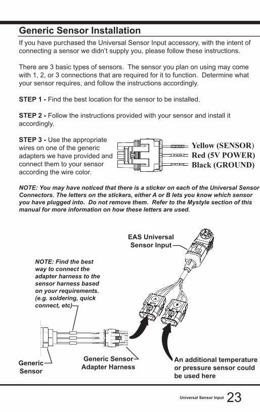
Generic Sensor InstallationIf you have purchased the Universal Sensor Input accessory, with the intent of connecting a sensor we didn’t supply you, please follow these instructions.
There are 3 basic types of sensors. The sensor you plan on using may come with 1, 2, or 3 connections that are required for it to function. Determine what your sensor requires, and follow the instructions accordingly.
STEP 1 - Find the best location for the sensor to be installed.
STEP 2 - Follow the instructions provided with your sensor and install it accordingly.
STEP 3 - Use the appropriate wires on one of the generic adapters we have provided and connect them to your sensor according the wire color.
NOTE: You may have noticed that there is a sticker on each of the Universal Sensor Connectors. The letters on the stickers, either A or B lets you know which sensor you have plugged into. Do not remove them. Refer to the Mystyle section of this manual for more information on how these letters are used.
Yellow (SENSOR)Red (5V POWER) Black (GROUND)
An additional temperature or pressure sensor could be used here
Generic SensorAdapter Harness
EAS Universal Sensor Input
Generic Sensor
NOTE: Find the best way to connect the adapter harness to the sensor harness based on your requirements. (e.g. soldering, quick connect, etc)
2424 Turbo Cool Down
Turbo Cool DownFuse Box Locations
Installing the Fuse Adapter
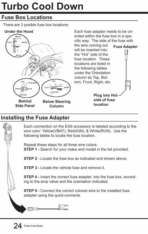
There are 3 posible fuse box locations:
Under the Hood
BehindSide Panel
Below Steering Column
Each fuse adapter needs to be ori-ented within the fuse box in a spe-cific way. The side of the fuse with the wire coming out will be inserted into the “Hot” side of the fuse location. These locations are listed in the following tables under the Orientation column as Top, Bot-tom, Front, Right, etc.
Plug into Hot side of fuse location
Fuse Adapter
Each connection on the EAS accessory is labeled according to the wire color: Yellow(VBAT), Red(IGN), & White(RUN). Use the following tables to locate the fuse location.
Repeat these steps for all three wire colors:STEP 1 - Search for your make and model in the list provided.
STEP 2 - Locate the fuse box as indicated and shown above.
STEP 3 - Locate the vehicle fuse and remove it.
STEP 4 - Insert the correct fuse adapter, into the fuse box, accord-ing to the amp value and the orientation indicated. STEP 5 - Connect the correct colored wire to the installed fuse adapter using the quick-connects.

2525Turbo Cool Down
TABLE 2 - IGN (Red Wire)
TRUCK YEAR FUSE BOX FUSE (amps) ORIENTATIONGM2001-2002 Under Hood TBC (10amp) Rear2003-2007 Under Hood TBC BATT (10amp) Rear
2007.5-2014 Under Hood IPC (10amp) Rear2015-2018 Under Hood 53 (10amp) RearFORD1994-1997 Steering Column 16 (15amp) Bottom1999-2001 Steering Column 4 (10amp) Left2002-2003 Steering Column 10 (10amp) Left2004-2007 Steering Column 2 (10amp) Left2008-2010 Under Hood 30 (10amp) Front2011-2016 Under Hood 46 (10amp) Left2017-2018 Under Hood 95(10amp) LeftDODGE1998.5-2002 Under Hood A/C CLUTCH (10amp) Front2003-2005 Under Hood 16 (10amp) Rear2006-2009 Under Hood 23 (10amp) Left2010 Under Hood M26 (10amp) Front2011-2012 Under Hood M27 (10amp) Right2013-2018 Under Hood 44 (10amp) Right
TABLE 1 - VBAT (Yellow Wire)
TRUCK YEAR FUSE BOX FUSE(amps) ORIENTATIONGM2001-2007 Under Hood IGN E (10amp) Rear2007.5-2014 Under Hood MISC ING (10amp) Rear2015-2018 Under Hood 39 (10amp) LeftFORD1994-1997 Steering Column 17 (10amp) Top1999-2001 Steering Column 19 (10amp) Right2002-2007 Steering Column 45 (10amp) Bottom2008-2010 Under Hood 77 (10amp) Front2011-2016 Under Hood 52 (10amp) Left2017-2018 Under Hood 33 (10amp) LeftDODGE1998.5-2002 Side Panel 9 (10amp) Bottom2003-2005 Under Hood 28 (10amp) Front2006-2012 Refer to “DODGE ADAPTER INSTALL” Section2013-2018 Under Hood 78 (10amp) Rear
NOTE: The following (3) tables have information for specific vehicles. If you do not see your vehicle here, refer to the Generic Installation section.

2626 Turbo Cool Down
TRUCK YEAR FUSE BOX FUSE(#/NAME) ORIENTATIONGM2001-2005 Side Panel BRAKE (10amp) Rear2006-2007 Side Panel BRK (10amp) Rear2007.5-2018 FUSE #3 Not needed for these trucksFORD1994-1997 Steering Column 18 (10amp) Bottom1999-2001 Steering Column 24 (10amp) Left2002-2003 Steering Column 26 (10amp) Right2003-2007 Steering Column 28 (10amp) Right2008-2018 FUSE #3 Not needed for these trucksDODGE1998.5-2002 FUSE #3 Not needed for these trucks2003-2005 Under Hood 35 (10amp) Front2006-2018 FUSE #3 Not needed for these trucksNOTE: On 2015 GM vehicles a check engine code (U0198) may be initiated when the turbo-timer is in use, but the check engine light will not turn on. The code can be cleared using the display device at any time.
TABLE 3 - RUN (White Wire)
For installation on vehicles not outlined previously:
VBAT CONNECTIONThe YELLOW VBAT connector should be connected to constant battery power. This could be done by connecting to the battery itself or any fuse that has con-stant power.IGN CONNECTIONThe RED “IGN” connector needs to be connected to the RUN-START circuit of the vehicle. This circuit has power when the key is in the run position and in the start/crank position. RUN CONNECTION The WHITE “RUN” connector may or may not be necessary. The RUN connector is used to power modules that would other wise generate codes if not powered while the turbo timer keeps the vehicle running. Typically these modules are connected to the RUN circuit of the vehicle. This circuit has power when the key is in the run po-sition and only in the run position. NOTE: If codes are set during or after using the turbo timer, the circuit that was touched with RUN is the wrong circuit.
WARNING: DO NOT use fuse locations that are for the AIR BAG / Supplement Restraint System.
Generic Installations
2727Turbo Cool Down
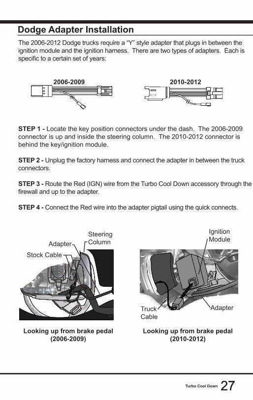
Dodge Adapter InstallationThe 2006-2012 Dodge trucks require a “Y” style adapter that plugs in between the ignition module and the ignition harness. There are two types of adapters. Each is specific to a certain set of years:
2006-2009 2010-2012
STEP 1 - Locate the key position connectors under the dash. The 2006-2009 connector is up and inside the steering column. The 2010-2012 connector is behind the key/ignition module.
STEP 2 - Unplug the factory harness and connect the adapter in between the truck connectors.
STEP 3 - Route the Red (IGN) wire from the Turbo Cool Down accessory through the firewall and up to the adapter.
STEP 4 - Connect the Red wire into the adapter pigtail using the quick connects.
Looking up from brake pedal (2006-2009)
Looking up from brake pedal (2010-2012)
Ignition Module
AdapterTruck Cable
Adapter
Stock Cable
Steering Column

2828 Power Switch
Power SwitchConnections
ADAPTER HARNESS
CONNECTOR
BLU
E
GR
EEN
RED
BLA
CK
KEYPOWER
RELAY 2
RELAY 1
BATTERYPOWER
BATTERYPOWER
LOAD 1
LOAD 2
CHASSISGROUND
CHASSISGROUND
CHASSISGROUND
85 87
86 30
85 87
86 30
+
-
+
-
A single EAS Power Switch gives you the ability to control two separate devices (e.g. light bars, spot lights, etc). Refer to the following instructions to learn how to properly connect a device to be controlled by an EAS Power Switch.
STEP 1 - Make sure the device(s) you are controlling came with an automotive grade relay. If not, you will need to purchase one.
TIP: You will need to make connections between the relays and each device you plan to control. We recommend using automotive quick disconnect style connec-tors that you can crimp onto the wires, and quickly install.
STEP 2 - Using the schematic below, make the proper connection to the load (what you are controlling), and the EAS adapter harness.
STEP 3 - Next plug the adapter into the Power Switch
To Relay
NOTE: If you are only controlling one device, you will only need to connect one relay. If this is the case, coil and secure the blue wire until future use.
Adapter Harness

2929Power Switch
Monitor Tools with Power Switch - Device 1STEP 1 - Once all of the proper connections are made, turn the key to the ON position.
STEP 2 - Enter the Quick Link menu (pull-up menu).
STEP 3 - Press the Screen Layout Icon
STEP 4 - Select either Layout 1 or Layout 2.
STEP 5 - Select the Switches screen option.
STEP 6- Return to the Home screen.
STEP 7 - Swipe horizontally to switch between your selected layouts.
Screen LayoutBackground
Layout 1 - Master
Layout 2 - Accelerometer
Screen Layout
Master Digital Retro
Needles Accelerometer Switches

30 Power Switch
6 Digital Gauges are also available on this screen.
Refer to the Individual Gauge Setup section for more information.
The display will detect the newly installed Power Switch during boot up. Once detected, the first two buttons (left) will automatically be populated.
STEP 8 - To toggle the switch On or Off, simply press the switch. The light indicator will illuminate when the switch is On.
If you would like to customize a switch:
STEP 9 - Touch and hold the switch for 3 second, then let off. A menu will appear.
STEP 10 - Select each option and make your adjustments accordingly:
12
3

31Power Switch
EAS SW1 (Green)Select New Switch
Rename Switch
Button Color
Switch Information
Exit Menu
The default name for each Power Switch that corresponds to the wire on the Power Switch pigtail.(SW2 is blue)
Allows you to select which device you are controlling. You may also Deactivate the switch location.
The new name can be up to two words with less than 12 characters per word.
Changes the color of the illuminated indicator when the switch is On.STEP 11 - Return to the Switch Screen to see the changes you have made.
Monitor Tools with Power Switch - Device 2For more information on how to select new PIDs, refer to the display device’s user manual. STEP 1 - Start the vehicle. NOTE: Once the Power Switch has been installed, the vehicle will need to be started so that the display device (i.e. Attitude, Evolution, or Insight) can detect the Power Switch.
STEP 2 - Press the Enter button. One of the PID locations will be highlighted.
STEP 3 - Use the arrow buttons to highlight the PID location you would like the Power Switch PID to be, then press Enter to open the PID Sub Menu.
STEP 4 - Choose “Select New PID” from the list.
STEP 5 - Scroll down through the list of available PIDs and select the EAS SW1 (Green) option. (or EAS SW2 (Blue) if you are controlling a second device).
STEP 6 - Return to the gauge screen.
STEP 7 - Press the Enter Button and use the arrow buttons to highlight the Power Switch PID.
STEP 8 - Press the Enter Button to turn ON/OFF the Power Switch.
NOTE: To change the PID location to something different, press and hold the Enter button for 3 seconds while the PID location is highlighted. This will open the PID menu.
EAS EGTSelect New PID
Alert Settings
Gauge Color
PID Information
Exit Menu
PID Select MenuEAS SW1 (Green)
EAS SW2 (Blue)
Engine Coolant Temp
Engine Load
Engine RPM

3232 Power Switch
Monitor Tools with Power Switch - Device 3
When an EAS Power Switch is connected this tool, a new switch page is automatically added to the Gauged mode. It is added in the very first slot, to the far left of the gauge pages. The switch page will be automatically populated with connected switches (up to 4). You also have the option of placing a switch on any digital gauge.
Switch Operation:• A single tap on a switch, or digital
gauge holding a switch, will change the state of the switch.
• A long press and hold on a switch, or digital gauge holding a switch, will enter the Switch Customization Menu.
Switch Customization Menu:Users can change the switch look, and LED color through this menu.
Gauges Mode Operation with EAS Power Switch connected:• If an EAS Switch module is present, the sleep timer is extended to 30
seconds. The 30 second timer is also used if a device is woken up by a tap (warm boot).
• If a switch is toggled to the ON position, the sleep timer is suspended until the switch is toggled to the OFF position. Once the switch is toggled OFF, the sleep timer will begin counting down.
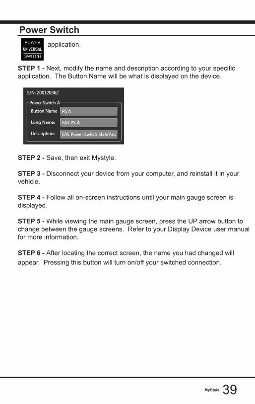
Display Name
Description
Current Settings
EAS PS

3333EAS 12V Power
EAS 12V PowerConnecting to PowerFor older vehicles not equipped with an OBDII port, a kit may be purchased along with an EAS 5V Sensor to provide vehicle parameters without OBDII.
STEP 1 - Locate a KEY-ON power source. A KEY-ON power source is only ON when the ignition is in the ON or RUN position. Connect the RED (+) wire to the KEY-ON source.
STEP 2 - Locate a bolt or other connection that is grounded to the chassis. Connect the Black (-) wire.
STEP 3 - Route the HDMI connector up to the display device (Insight).
STEP 4 - Plug the HDMI connector into the back of the display device (Insight).
STEP 5 - Plug the EAS system into the 6 Pin connector.
34 MyStyle
MyStyleStarting MyStyleNOTE: MyStyle is only for use with the Edge Products CS, CTS, CS2, and CTS2. If your tool/monitor is not one of the previously mentioned devices, check the user manual for your tool/monitor for instructions on EAS compatibility and customization.
This section explains how to use the MyStyle software to configure your sensor output data so it can be read and interpreted properly on your Display device. In order for you to complete the following steps, you will need: 1) Access to a computer. 2) Display Device 3) USB Cable (See Quick Install Guide) 4) MyStyle Program installed on your computer.
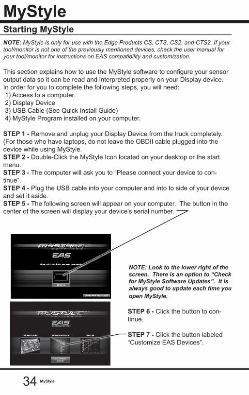
STEP 1 - Remove and unplug your Display Device from the truck completely. (For those who have laptops, do not leave the OBDII cable plugged into the device while using MyStyle.STEP 2 - Double-Click the MyStyle Icon located on your desktop or the start menu. STEP 3 - The computer will ask you to “Please connect your device to con-tinue”.STEP 4 - Plug the USB cable into your computer and into to side of your device and set it aside. STEP 5 - The following screen will appear on your computer. The button in the center of the screen will display your device’s serial number.
NOTE: Look to the lower right of the screen. There is an option to “Check for MyStyle Software Updates”. It is always good to update each time you open MyStyle. STEP 6 - Click the button to con-tinue.
STEP 7 - Click the button labeled “Customize EAS Devices”.
35MyStyle
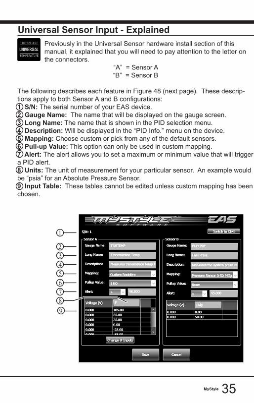
Universal Sensor Input - ExplainedPreviously in the Universal Sensor hardware install section of this manual, it explained that you will need to pay attention to the letter on the connectors.
“A” = Sensor A“B” = Sensor B
The following describes each feature in Figure 48 (next page). These descrip-tions apply to both Sensor A and B configurations:1 S/N: The serial number of your EAS device. 2 Gauge Name: The name that will be displayed on the gauge screen.3 Long Name: The name that is shown in the PID selection menu.4 Description: Will be displayed in the “PID Info.” menu on the device. 5 Mapping: Choose custom or pick from any of the default sensors.6 Pull-up Value: This option can only be used in custom mapping. 7 Alert: The alert allows you to set a maximum or minimum value that will trigger a PID alert. 8 Units: The unit of measurement for your particular sensor. An example would be “psia” for an Absolute Pressure Sensor. 9 Input Table: These tables cannot be edited unless custom mapping has been chosen.
1
2
543
76
89
36 MyStyle
Universal Sensor Input - Custom MappingIf you chose to install a sensor that is not called out as a default sensor, you may chose to create custom mapping.
STEP 1 - Choose the custom mapping option according to your type of sensor. The two choices are:
Voltage (V)Resistance (ohms)
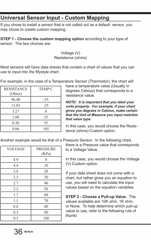
Most sensors will have data sheets that contain a chart of values that you can use to input into the Mystyle chart. For example, in the case of a Temperature Sensor (Thermistor), the chart will
have a temperature value (Usually in degrees Celsius) that corresponds to a resistance value.
NOTE: It is important that you label your units properly. For example, if your chart gives you degrees in Celsius, make certain that the Unit of Measure you input matches that value type.
In this case, you would choose the Resis-tance (ohms) Custom option.
Another example would be that of a Pressure Sensor. In the following chart, there is a Pressure value that corresponds to a Voltage Value. In this case, you would choose the Voltage (V) Custom option.
If your data sheet does not come with a chart, but rather gives you an equation to use, you will need to calculate the input values based on the equation variables.
STEP 2 - Choose a Pull-up Value. The values available are 10K ohm, 1K ohm, or None. To help determine which pull-up value to use, refer to the following rule of thumb:
RESISTANCE (Ohms)
TEMP C
96.40 -5513.03 -253.27 01.00 250.30 550.06 105
VOLTAGE PRESSURE (KPa)
4.9 04.4 103.8 203.3 302.7 402.2 501.7 601.1 700.6 800.3 900.3 100

37MyStyle
-3 wire sensors: None-2 or 1 wire sensors: 1K or 10K
If for example your sensor is a single wire Temperature sensor, and is rated as 1K @ 25C, you would want to use a 1K pull-up. You want to match your pull-up value as close to the sensor rating as possible.
STEP 3 - Set the alert value according to your specific sensor. Depending on the sensor, the alert value will be either a maximum or a minimum value.
For example, if you have a pressure sensor, and you want the device to alert you when the sensor reads greater than or equal to 90 psi, set up the values as shown:
STEP 4 - Fill in the Unit of Measure value. This will be displayed on the main gauge screen. Only 4 digits are allowed. STEP 5 - Input the chart data. Most sensors will have data sheets that contain a chart of values that you can input into the Mystyle chart. These will look similar to the charts in Figures 49 and 50 on the previous pages.
For non-linear output sensors, the more data points you can enter, the more ac-curate your custom mapping will be. When the sensor output is linear, only the maximum and minimum values are needed.
NOTE: You probably noticed the button in the upper right hand corner labeled “Switch to CNG”. We offer CNG kits for fleet vehicles, which are not yet available to individual users. This allows them to modify a PID that uses temperature and pres-sure to calculate the fuel level in their CNG tank. STEP 7 - Click the “Save” button, and you will be directed to the previous screen.
STEP 8 - Click the “Save Configuration” button to upload the changes to your Display Device.
38 MyStyle
EGT Sensor
Display Setup
If you are modifying an EGT Device, note that you are only allowed to change the names and descriptions.
STEP 1 - Update/change names and description.
STEP 2 - Click the “Save” button, and you will be directed to the previous screen.
STEP 3 - Click the “Save Configuration” button to upload the changes to your Display Device.
Now that you have modified and saved your Mystyle data, you can setup and display your EGT or Universal Sensor Input PIDs on the Display Device.
STEP 1 - Disconnect your device from Mystyle, and reinstall it in your truck.
STEP 2 - Follow all on-screen instructions until your main gauge screen is dis-played.
STEP 3 - While viewing the main gauge screen, choose the gauge you would like to modify.
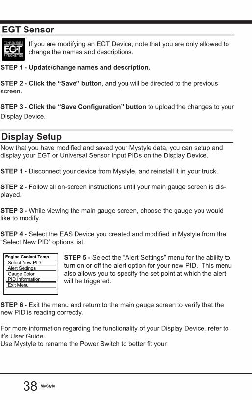
STEP 4 - Select the EAS Device you created and modified in Mystyle from the “Select New PID” options list.
STEP 5 - Select the “Alert Settings” menu for the ability to turn on or off the alert option for your new PID. This menu also allows you to specify the set point at which the alert will be triggered.
STEP 6 - Exit the menu and return to the main gauge screen to verify that the new PID is reading correctly.
For more information regarding the functionality of your Display Device, refer to it’s User Guide. Use Mystyle to rename the Power Switch to better fit your
Engine Coolant Temp
Gauge ColorPID InformationExit Menu
Alert SettingsSelect New PID
MENU
ENTER
39MyStyle
Power Switchapplication.
STEP 1 - Next, modify the name and description according to your specific application. The Button Name will be what is displayed on the device.
STEP 2 - Save, then exit Mystyle.
STEP 3 - Disconnect your device from your computer, and reinstall it in your vehicle.
STEP 4 - Follow all on-screen instructions until your main gauge screen is displayed.
STEP 5 - While viewing the main gauge screen, press the UP arrow button to change between the gauge screens. Refer to your Display Device user manual for more information.
STEP 6 - After locating the correct screen, the name you had changed will appear. Pressing this button will turn on/off your switched connection.

Copyright© 2019D10006700 Rev01 11/13/2019
For additional questions not found in the user guide call:Edge Products Technical Support: (888) 360-EDGE (3343) 6:00 am - 6:00 pm MST
To expedite your support call, please have your Vehicle Information, Part Number, and Serial Number ready prior to calling Technical Support.