efi fiery® central integrated serverhelp.efi.com/fierycentral/2.8/45140887_fierycentral_isg.pdfefi...
TRANSCRIPT
EFI Fiery® Central integrated server
Service GuideA guide for service technicians
Replacement parts and specifications are subject to change. For the most current parts list, contact your authorized service/support center.

© 2015 Electronics For Imaging, Inc.
This documentation is protected by copyright, and all rights are reserved. No part of it may be reproduced or transmitted in any form or by any means for any purpose without express prior written consent from Electronics For Imaging, Inc. (“EFI”), except as expressly permitted herein. Information in this documentation is subject to change without notice and does not represent a commitment on the part of EFI. The documentation is further covered by Legal Notices distributed with this product. The documentation may be provided in conjunction with EFI Software (“Software”) and any other EFI product described in the documentation. The Software is furnished under license and may only be used or copied in accordance with the terms of the Software License Agreement, which can be found in the “Legal Notices” distributed with this product.
13 November 2015 45140887
*45140887*

List of Figures . . . . . . . . . . . . . . . . . . . . . . . . . . . . . . . . . . . . . . . . . . . . . . . . . . . . . . . . . . . . . . . . . . . . . . . . . . . . . . . . . . . . . . . . . . . . . . . . 5
Introduction . . . . . . . . . . . . . . . . . . . . . . . . . . . . . . . . . . . . . . . . . . . . . . . . . . . . . . . . . . . . . . . . . . . . . . . . . . . . . . . . . . . . . . . . . . . . . . . . . . 6
About the Fiery Central integrated server. . . . . . . . . . . . . . . . . . . . . . . . . . . . . . . . . . . . . . . . . . . . . . . . . . . . . . . . . . . . . . . . . . . . . . . . . . 6
Preparing for service procedures . . . . . . . . . . . . . . . . . . . . . . . . . . . . . . . . . . . . . . . . . . . . . . . . . . . . . . . . . . . . . . . . . . . . . . . . . . . . . . . . . . 6
Precautions . . . . . . . . . . . . . . . . . . . . . . . . . . . . . . . . . . . . . . . . . . . . . . . . . . . . . . . . . . . . . . . . . . . . . . . . . . . . . . . . . . . . . . . . . . . . . . . . . . . . 6
Creating an electrostatic discharge (ESD) safe environment. . . . . . . . . . . . . . . . . . . . . . . . . . . . . . . . . . . . . . . . . . . . . . . . . . . . . . 8
Tools you will need . . . . . . . . . . . . . . . . . . . . . . . . . . . . . . . . . . . . . . . . . . . . . . . . . . . . . . . . . . . . . . . . . . . . . . . . . . . . . . . . . . . . . . . . . . . . . . . 9
Using the Fiery Central integrated server . . . . . . . . . . . . . . . . . . . . . . . . . . . . . . . . . . . . . . . . . . . . . . . . . . . . . . . . . . . . . 10
Overview. . . . . . . . . . . . . . . . . . . . . . . . . . . . . . . . . . . . . . . . . . . . . . . . . . . . . . . . . . . . . . . . . . . . . . . . . . . . . . . . . . . . . . . . . . . . . . . . . . . . . . . . 10
Using the Fiery Central integrated server control panel . . . . . . . . . . . . . . . . . . . . . . . . . . . . . . . . . . . . . . . . . . . . . . . . . . . . . . . . . . . 10
Buttons . . . . . . . . . . . . . . . . . . . . . . . . . . . . . . . . . . . . . . . . . . . . . . . . . . . . . . . . . . . . . . . . . . . . . . . . . . . . . . . . . . . . . . . . . . . . . . . . . . . . . . 11
Network status LEDs . . . . . . . . . . . . . . . . . . . . . . . . . . . . . . . . . . . . . . . . . . . . . . . . . . . . . . . . . . . . . . . . . . . . . . . . . . . . . . . . . . . . . . . . . . . . . 11
Starting, shutting down, restarting, and rebooting. . . . . . . . . . . . . . . . . . . . . . . . . . . . . . . . . . . . . . . . . . . . . . . . . . . . . . . . . . . . . . . . 11
Definitions. . . . . . . . . . . . . . . . . . . . . . . . . . . . . . . . . . . . . . . . . . . . . . . . . . . . . . . . . . . . . . . . . . . . . . . . . . . . . . . . . . . . . . . . . . . . . . . . . . . . 11
Replacing parts . . . . . . . . . . . . . . . . . . . . . . . . . . . . . . . . . . . . . . . . . . . . . . . . . . . . . . . . . . . . . . . . . . . . . . . . . . . . . . . . . . . . . . . . . . . . . 13
Overview. . . . . . . . . . . . . . . . . . . . . . . . . . . . . . . . . . . . . . . . . . . . . . . . . . . . . . . . . . . . . . . . . . . . . . . . . . . . . . . . . . . . . . . . . . . . . . . . . . . . . . . . 13
Fiery Central integrated server overview diagrams . . . . . . . . . . . . . . . . . . . . . . . . . . . . . . . . . . . . . . . . . . . . . . . . . . . . . . . . . . . . . 14
Accessing internal components . . . . . . . . . . . . . . . . . . . . . . . . . . . . . . . . . . . . . . . . . . . . . . . . . . . . . . . . . . . . . . . . . . . . . . . . . . . . . . . . . . 18
Shutting down the system . . . . . . . . . . . . . . . . . . . . . . . . . . . . . . . . . . . . . . . . . . . . . . . . . . . . . . . . . . . . . . . . . . . . . . . . . . . . . . . . . . . . 18
Opening the Fiery Central integrated server. . . . . . . . . . . . . . . . . . . . . . . . . . . . . . . . . . . . . . . . . . . . . . . . . . . . . . . . . . . . . . . . . . . . 18
Removing and replacing boards . . . . . . . . . . . . . . . . . . . . . . . . . . . . . . . . . . . . . . . . . . . . . . . . . . . . . . . . . . . . . . . . . . . . . . . . . . . . . . . . . 23
User interface board assembly. . . . . . . . . . . . . . . . . . . . . . . . . . . . . . . . . . . . . . . . . . . . . . . . . . . . . . . . . . . . . . . . . . . . . . . . . . . . . . . . . 23
Motherboard . . . . . . . . . . . . . . . . . . . . . . . . . . . . . . . . . . . . . . . . . . . . . . . . . . . . . . . . . . . . . . . . . . . . . . . . . . . . . . . . . . . . . . . . . . . . . . . . . . . . 26
Removing the motherboard . . . . . . . . . . . . . . . . . . . . . . . . . . . . . . . . . . . . . . . . . . . . . . . . . . . . . . . . . . . . . . . . . . . . . . . . . . . . . . . . . . . 26
Replacing the motherboard . . . . . . . . . . . . . . . . . . . . . . . . . . . . . . . . . . . . . . . . . . . . . . . . . . . . . . . . . . . . . . . . . . . . . . . . . . . . . . . . . . . 30
Replacing parts on the motherboard . . . . . . . . . . . . . . . . . . . . . . . . . . . . . . . . . . . . . . . . . . . . . . . . . . . . . . . . . . . . . . . . . . . . . . . . . . . . . 32
DIMMs. . . . . . . . . . . . . . . . . . . . . . . . . . . . . . . . . . . . . . . . . . . . . . . . . . . . . . . . . . . . . . . . . . . . . . . . . . . . . . . . . . . . . . . . . . . . . . . . . . . . . . . . 33
CPU . . . . . . . . . . . . . . . . . . . . . . . . . . . . . . . . . . . . . . . . . . . . . . . . . . . . . . . . . . . . . . . . . . . . . . . . . . . . . . . . . . . . . . . . . . . . . . . . . . . . . . . . . . 33
Battery . . . . . . . . . . . . . . . . . . . . . . . . . . . . . . . . . . . . . . . . . . . . . . . . . . . . . . . . . . . . . . . . . . . . . . . . . . . . . . . . . . . . . . . . . . . . . . . . . . . . . . . 37
Jumpers . . . . . . . . . . . . . . . . . . . . . . . . . . . . . . . . . . . . . . . . . . . . . . . . . . . . . . . . . . . . . . . . . . . . . . . . . . . . . . . . . . . . . . . . . . . . . . . . . . . . . . 39
Fan. . . . . . . . . . . . . . . . . . . . . . . . . . . . . . . . . . . . . . . . . . . . . . . . . . . . . . . . . . . . . . . . . . . . . . . . . . . . . . . . . . . . . . . . . . . . . . . . . . . . . . . . . . . . . . 39
Contents

4Service Guide: EFI Fiery Central interated serverContents
Power supply. . . . . . . . . . . . . . . . . . . . . . . . . . . . . . . . . . . . . . . . . . . . . . . . . . . . . . . . . . . . . . . . . . . . . . . . . . . . . . . . . . . . . . . . . . . . . . . . . . . . 40
Hard disk drive . . . . . . . . . . . . . . . . . . . . . . . . . . . . . . . . . . . . . . . . . . . . . . . . . . . . . . . . . . . . . . . . . . . . . . . . . . . . . . . . . . . . . . . . . . . . . . . . . . 43
Switch bank assembly . . . . . . . . . . . . . . . . . . . . . . . . . . . . . . . . . . . . . . . . . . . . . . . . . . . . . . . . . . . . . . . . . . . . . . . . . . . . . . . . . . . . . . . . . . . 48
DVD drive . . . . . . . . . . . . . . . . . . . . . . . . . . . . . . . . . . . . . . . . . . . . . . . . . . . . . . . . . . . . . . . . . . . . . . . . . . . . . . . . . . . . . . . . . . . . . . . . . . . . . . . 52
Restoring and verifying functionality after service . . . . . . . . . . . . . . . . . . . . . . . . . . . . . . . . . . . . . . . . . . . . . . . . . . . . . . . . . . . . . . . . 53
Installing Fiery Central integrated server Software . . . . . . . . . . . . . . . . . . . . . . . . . . . . . . . . . . . . . . . . . . . . . . . . . 55
Server software installation . . . . . . . . . . . . . . . . . . . . . . . . . . . . . . . . . . . . . . . . . . . . . . . . . . . . . . . . . . . . . . . . . . . . . . . . . . . . . . . . . . . . . . 55
Installing the system software . . . . . . . . . . . . . . . . . . . . . . . . . . . . . . . . . . . . . . . . . . . . . . . . . . . . . . . . . . . . . . . . . . . . . . . . . . . . . . . . . 55
Fiery Central License Manager . . . . . . . . . . . . . . . . . . . . . . . . . . . . . . . . . . . . . . . . . . . . . . . . . . . . . . . . . . . . . . . . . . . . . . . . . . . . . . . . . . . 56
Installing the hardware security key . . . . . . . . . . . . . . . . . . . . . . . . . . . . . . . . . . . . . . . . . . . . . . . . . . . . . . . . . . . . . . . . . . . . . . . . . . . . . . 57
Configuring Fiery Central integrated server . . . . . . . . . . . . . . . . . . . . . . . . . . . . . . . . . . . . . . . . . . . . . . . . . . . . . . . . . . . . . . . . . . . . . . . 58
Fiery Central Configure. . . . . . . . . . . . . . . . . . . . . . . . . . . . . . . . . . . . . . . . . . . . . . . . . . . . . . . . . . . . . . . . . . . . . . . . . . . . . . . . . . . . . . . . 59
Troubleshooting. . . . . . . . . . . . . . . . . . . . . . . . . . . . . . . . . . . . . . . . . . . . . . . . . . . . . . . . . . . . . . . . . . . . . . . . . . . . . . . . . . . . . . . . . . . . 61
Troubleshooting process. . . . . . . . . . . . . . . . . . . . . . . . . . . . . . . . . . . . . . . . . . . . . . . . . . . . . . . . . . . . . . . . . . . . . . . . . . . . . . . . . . . . . . . . . 61
Preliminary on-site checkout . . . . . . . . . . . . . . . . . . . . . . . . . . . . . . . . . . . . . . . . . . . . . . . . . . . . . . . . . . . . . . . . . . . . . . . . . . . . . . . . . . . . . 61
Checking external connections . . . . . . . . . . . . . . . . . . . . . . . . . . . . . . . . . . . . . . . . . . . . . . . . . . . . . . . . . . . . . . . . . . . . . . . . . . . . . . . . 62
Checking internal components . . . . . . . . . . . . . . . . . . . . . . . . . . . . . . . . . . . . . . . . . . . . . . . . . . . . . . . . . . . . . . . . . . . . . . . . . . . . . . . . 63
Inspecting the system. . . . . . . . . . . . . . . . . . . . . . . . . . . . . . . . . . . . . . . . . . . . . . . . . . . . . . . . . . . . . . . . . . . . . . . . . . . . . . . . . . . . . . . . . 63
Normal startup sequence . . . . . . . . . . . . . . . . . . . . . . . . . . . . . . . . . . . . . . . . . . . . . . . . . . . . . . . . . . . . . . . . . . . . . . . . . . . . . . . . . . . . . 66
Error messages and conditions . . . . . . . . . . . . . . . . . . . . . . . . . . . . . . . . . . . . . . . . . . . . . . . . . . . . . . . . . . . . . . . . . . . . . . . . . . . . . . . . . . . 67
Specifications . . . . . . . . . . . . . . . . . . . . . . . . . . . . . . . . . . . . . . . . . . . . . . . . . . . . . . . . . . . . . . . . . . . . . . . . . . . . . . . . . . . . . . . . . . . . . . . 75
Hardware features . . . . . . . . . . . . . . . . . . . . . . . . . . . . . . . . . . . . . . . . . . . . . . . . . . . . . . . . . . . . . . . . . . . . . . . . . . . . . . . . . . . . . . . . . . . . 75
Physical specifications. . . . . . . . . . . . . . . . . . . . . . . . . . . . . . . . . . . . . . . . . . . . . . . . . . . . . . . . . . . . . . . . . . . . . . . . . . . . . . . . . . . . . . . . . 75
Networking and connectivity. . . . . . . . . . . . . . . . . . . . . . . . . . . . . . . . . . . . . . . . . . . . . . . . . . . . . . . . . . . . . . . . . . . . . . . . . . . . . . . . . . 75
Safety and emissions compliance. . . . . . . . . . . . . . . . . . . . . . . . . . . . . . . . . . . . . . . . . . . . . . . . . . . . . . . . . . . . . . . . . . . . . . . . . . . . . . 75
Servicing the Fiery Central integrated server with furniture . . . . . . . . . . . . . . . . . . . . . . . . . . . . . . . . . . . . . . 77
Procedures . . . . . . . . . . . . . . . . . . . . . . . . . . . . . . . . . . . . . . . . . . . . . . . . . . . . . . . . . . . . . . . . . . . . . . . . . . . . . . . . . . . . . . . . . . . . . . . . . . . . . . 77
Index . . . . . . . . . . . . . . . . . . . . . . . . . . . . . . . . . . . . . . . . . . . . . . . . . . . . . . . . . . . . . . . . . . . . . . . . . . . . . . . . . . . . . . . . . . . . . . . . . . . . . . . . . . 86

Figure 1: FC integrated control panel . . . . . . . . . . . . . . . . . . . . . . . . . . . . . . . . . . . . . . . . . . . . . . . . . . . . . . . . . . . . . . . . . . . . . . . . . . 10
Figure 2: Front panel and connector panel . . . . . . . . . . . . . . . . . . . . . . . . . . . . . . . . . . . . . . . . . . . . . . . . . . . . . . . . . . . . . . . . . . . . . 14
Figure 3: Internal side view . . . . . . . . . . . . . . . . . . . . . . . . . . . . . . . . . . . . . . . . . . . . . . . . . . . . . . . . . . . . . . . . . . . . . . . . . . . . . . . . . . . . 15
Figure 4: Exploded view of components . . . . . . . . . . . . . . . . . . . . . . . . . . . . . . . . . . . . . . . . . . . . . . . . . . . . . . . . . . . . . . . . . . . . . . . 16
Figure 5: Power and data cable connections . . . . . . . . . . . . . . . . . . . . . . . . . . . . . . . . . . . . . . . . . . . . . . . . . . . . . . . . . . . . . . . . . . . 17
Figure 6: Removing/replacing the side panels . . . . . . . . . . . . . . . . . . . . . . . . . . . . . . . . . . . . . . . . . . . . . . . . . . . . . . . . . . . . . . . . . . 20
Figure 7: Removing/replacing the front panel . . . . . . . . . . . . . . . . . . . . . . . . . . . . . . . . . . . . . . . . . . . . . . . . . . . . . . . . . . . . . . . . . . 21
Figure 8: Removing/replacing the top panel . . . . . . . . . . . . . . . . . . . . . . . . . . . . . . . . . . . . . . . . . . . . . . . . . . . . . . . . . . . . . . . . . . . 22
Figure 9: Diagram of the user interface board (front and back) . . . . . . . . . . . . . . . . . . . . . . . . . . . . . . . . . . . . . . . . . . . . . . . . . . 24
Figure 10: Removing/replacing the user interface board. . . . . . . . . . . . . . . . . . . . . . . . . . . . . . . . . . . . . . . . . . . . . . . . . . . . . . . . 25
Figure 11: Removing/replacing the UIB buttons . . . . . . . . . . . . . . . . . . . . . . . . . . . . . . . . . . . . . . . . . . . . . . . . . . . . . . . . . . . . . . . . 26
Figure 12: Motherboard . . . . . . . . . . . . . . . . . . . . . . . . . . . . . . . . . . . . . . . . . . . . . . . . . . . . . . . . . . . . . . . . . . . . . . . . . . . . . . . . . . . . . . . 28
Figure 13: CPU cooling assembly . . . . . . . . . . . . . . . . . . . . . . . . . . . . . . . . . . . . . . . . . . . . . . . . . . . . . . . . . . . . . . . . . . . . . . . . . . . . . . 34
Figure 14: Removing/replacing the CPU . . . . . . . . . . . . . . . . . . . . . . . . . . . . . . . . . . . . . . . . . . . . . . . . . . . . . . . . . . . . . . . . . . . . . . . 36
Figure 15: Motherboard battery . . . . . . . . . . . . . . . . . . . . . . . . . . . . . . . . . . . . . . . . . . . . . . . . . . . . . . . . . . . . . . . . . . . . . . . . . . . . . . . 38
Figure 16: Removing the fan. . . . . . . . . . . . . . . . . . . . . . . . . . . . . . . . . . . . . . . . . . . . . . . . . . . . . . . . . . . . . . . . . . . . . . . . . . . . . . . . . . . 40
Figure 17: Removing/replacing the power supply . . . . . . . . . . . . . . . . . . . . . . . . . . . . . . . . . . . . . . . . . . . . . . . . . . . . . . . . . . . . . . 42
Figure 18: FC integrated hard disk drive. . . . . . . . . . . . . . . . . . . . . . . . . . . . . . . . . . . . . . . . . . . . . . . . . . . . . . . . . . . . . . . . . . . . . . . . 45
Figure 19: Removing/replacing the hard disk drive bracket . . . . . . . . . . . . . . . . . . . . . . . . . . . . . . . . . . . . . . . . . . . . . . . . . . . . . 46
Figure 20: Removing/replacing the hard disk drive from/in the hard disk drive bracket . . . . . . . . . . . . . . . . . . . . . . . . . . 47
Figure 21: component sled with switch bank assembly . . . . . . . . . . . . . . . . . . . . . . . . . . . . . . . . . . . . . . . . . . . . . . . . . . . . . . . . . 49
Figure 22: Removing/replacing the component sled from the chassis . . . . . . . . . . . . . . . . . . . . . . . . . . . . . . . . . . . . . . . . . . . 50
Figure 23: Removing/replacing the switch bank assembly . . . . . . . . . . . . . . . . . . . . . . . . . . . . . . . . . . . . . . . . . . . . . . . . . . . . . . 51
Figure 24: Removing/replacing the DVD drive . . . . . . . . . . . . . . . . . . . . . . . . . . . . . . . . . . . . . . . . . . . . . . . . . . . . . . . . . . . . . . . . . 53
Figure 25: FC integrated external cable connections . . . . . . . . . . . . . . . . . . . . . . . . . . . . . . . . . . . . . . . . . . . . . . . . . . . . . . . . . . . 62
Figure 26: FC integrated installed on the furniture . . . . . . . . . . . . . . . . . . . . . . . . . . . . . . . . . . . . . . . . . . . . . . . . . . . . . . . . . . . . . 77
List of Figures

Introduction
This document includes information about servicing the EFI Fiery Central integrated server. In this document, EFI Fiery Central integrated server is referred to as “the FC integrated.”
About the Fiery Central integrated serverFC integrated is a server computer that runs Fiery Central software. Fiery Central software is a modular, PDF-based production workflow tool that provides efficient load-balanced network printing to high-volume print environments.
For more information on Fiery Central software, refer to the documentation that is included in the software kit.
Preparing for service proceduresBefore installing or servicing the FC integrated, follow general precautions and obtain the correct tools.
Precautions
• Use a soft cloth moistened with Lens and Mirror Cleaner to clean the surface of the FC integrated display window.
Other solvents, such as water, may damage the polarizer on the display window.
ATTENTION: Ne jamais soulever le serveur d’impression par sa partie supérieure : celle-ci ne peut pas supporter le poids du système.
AVVERTENZA: Il server di stampa non deve essere mai sollevato afferrandolo dal pannello superiore, in quanto quest’ultimo non può sostenere il peso dell’intero sistema.
WARNUNG: Heben Sie den Druckserver nicht an der oberen Gehäuseabdeckung an. Die obere Gehäuseabdeckung ist nicht dafür ausgelegt, das Gesamtgewicht des Systems zu tragen.
ADVERTENCIA: No levante nunca el servidor de impresión agarrándolo por el panel superior. El panel superior no soporta el peso del sistema.
ADVERTÊNCIA: Nunca erga o servidor de impressão pelo painel superior. O painel superior não suporta o peso do sistema.
WAARSCHUWING: Til de afdrukserver nooit op door het bovenpaneel vast te nemen. Het bovenpaneel kan het gewicht van het systeem niet dragen.
Caution: Avoid pressing the surface of the LCD.
Applying excessive pressure to the LCD window causes it to change color.
Warning: Never lift the FC integrated by grasping the top panel. The top panel does not support the weight of the system.

7Service Guide: EFI Fiery Central integrated serverIntroduction
• The FC integrated contains hazardous moving parts. When servicing the FC integrated, keep away from moving fan blades.
• Only use the power cord that shipped with the FC integrated or an appropriate replacement power cord available from an authorized provider.
• Always disconnect the power cord from the FC integrated connector panel before opening the unit and servicing internal components.
• Do not pull on the power cord when unplugging the FC integrated. Instead, pull the plug.
• Do not place objects on the power cord. Place the power cord away from foot traffic.
• Do not tamper with or disable the power cord grounding plug.
• Do not use a 3-prong adapter in a 2-hole, ungrounded outlet.
• Do not use an extension cord.
• Do not plug the FC integrated into a circuit with heating or refrigeration equipment (including water dispensers).
• Do not plug the FC integrated into a switchable power outlet. This can result in the FC integrated being turned off accidentally.
• Never set any liquid on or near the FC integrated. If liquid is spilled into the FC integrated, disconnect the power cord immediately.
• Do not attempt to open the power supply, DVD drive, or hard disk drive.
• Handle the FC integrated LCD window with care.
If the FC integrated LCD window breaks and the liquid crystal inside leaks out, avoid contact. If you come in contact with the liquid crystal, immediately wash it off your skin with soap and water.
• Use care when handling parts of the FC integrated, as some edges on the unit may be sharp.
• Do not install third-party applications onto the FC integrated. Third-party applications are not supported and can cause system problems. Although virus scans are permitted on the FC integrated, antivirus software should not be loaded in memory-resident mode.
Warning: The FC integrated contains hazardous moving parts. When servicing the FC integrated, keep away from moving fan blades.
Important: When connecting or disconnecting the power cord:

8Service Guide: EFI Fiery Central integrated serverIntroduction
• Do not change the Windows operating system software preference settings.
Depending on the changes made, the FC integrated may become unstable or even unusable. If this occurs, we recommend that you reinstall the FC integrated System Software, which reliably restores the Windows operating system software to its factory defaults.
• Never alter an existing network without permission.
The FC integrated will probably be connected to an existing Local Area Network (LAN) based on Ethernet hardware. The network is the link between the customer’s computer, existing laser printers, and other prepress equipment. Never disturb the LAN by breaking or making a network connection, altering termination, installing or removing networking hardware or software, or shutting down networked devices without the knowledge and explicit permission of the system or network administrator or shop supervisor.
• Unless you are the network administrator, never assign an IP address in FC integrated Network Setup.
In a DHCP environment, the system assigns the IP address automatically. In a non-DHCP environment, enter only the IP address that has been assigned by the network administrator. Only the network administrator should assign an IP address to a network device. Assigning the FC integrated an incorrect IP address may cause unpredictable errors on any or all devices connected to the network.
Creating an electrostatic discharge (ESD) safe environment
Static is always a concern when servicing electronic devices. It is highly unlikely that the area around the FC integrated is static-free. Carpeting, leather-soled shoes, synthetic clothing fibers, silks, and plastics may generate a static charge of more than 10,000 volts. Static discharge is capable of destroying the circuits etched in silicon microchips, or dramatically shortening their life span. By observing standard precautions, you may avoid extra service calls and save the cost of a new board.
When possible, work on a ground-connected antistatic mat. Wear an antistatic grounding strap, grounded at the same place as the antistatic mat. If that is not possible, do the following:
• Attach a grounding strap to your wrist. Attach the other end to a good ground.
• When you unpack the FC integrated from the carton for the first time, touch a metal area of other device or equipment to discharge the static on your body.
• Before you remove any of the FC integrated panels and handle internal components, touch a metal part of the FC integrated.
• Leave new electronic components inside their antistatic bags until you are ready to install them. When you remove components from an antistatic bag, place them on a grounded antistatic surface, component-side up.
• When you remove an electronic component, place it in an antistatic bag immediately. Do not walk across a carpet or vinyl floor while carrying an unprotected board.
Important: Follow standard ESD precautions while working on the internal components of the FC integrated.

9Service Guide: EFI Fiery Central integrated serverIntroduction
• During service to the motherboard, avoid using excessive force and always place the motherboard on a grounded, non-metallic, antistatic surface. Never allow any metal to touch the solder contacts on the underside of the motherboard, especially beneath the battery socket. Improper handling can short circuit and permanently damage the motherboard.
• Handle printed circuit boards by their opposing edges only and avoid touching the contacts on the edge of the board.
Tools you will needTo install or service the FC integrated, you will need the following tools and parts:
• ESD wrist grounding strap and antistatic mat
• Flathead screwdriver
• #0, #1, and #2 Phillips head screwdrivers
• Needlenose pliers
• FC integrated documentation, including the customer media pack and any related service bulletins
Important: Avoid touching magnetic tools to storage media such as hard disk drives. Contact between magnetic tools and magnetic storage media may result in data corruption.

Using the Fiery Central integrated server
This chapter includes the following information:
• Using the FC integrated control panel
• Checking Network status LEDs
• Shutting down and restarting the FC integrated
OverviewTwo main user interfaces are available for the FC integrated:
• The control panel on the front of the FC integrated (see following figure)
• The Fiery Advanced Controller Interface (FACI), which includes a monitor, keyboard, and mouse.
Using the Fiery Central integrated server control panelDuring normal FC integrated operation, the control panel displays a static logo screen and the buttons are not functional. However, during installation of FC integrated server software, the control panel displays screens that allow you to proceed through the steps of the installation.
Figure 1: FC integrated control panel
1 Activity light 5 Display window
2 Up button 6 First
3 Menu button 7 Line selection buttons
4 Down button 8 Fourth
1
2
3
4
5
6
7
8

11Service Guide: EFI Fiery Central interated serverUsing the Fiery Central integrated server
Buttons
Network status LEDsTwo LEDs next to the Ethernet connector indicate the network speed. When a data transfer occurs between the FC integrated and the network, the appropriate LED(s) blink to indicate network activity.
Starting, shutting down, restarting, and rebooting The customer will generally leave the FC integrated on all of the time. Power off the FC integrated when you need to service it and before you remove or attach any cables to it.
Definitions
• Restart Fiery Central (soft reset)—Resets the FC integrated server software, but does not reboot the entire system. Network access to the FC integrated is temporarily interrupted and all currently processing jobs are aborted and may be lost.
• Reboot System (hard reset)—Shuts down all FC integrated activity properly, and then reboots.
• Shut Down System—Shuts down all FC integrated server software and powers off the system. Always select this option to power off the system.
Always use the following procedures when shutting down, restarting, or rebooting the FC integrated.
Note: Use the reset button on the front of the FC integrated only if the system is unresponsive to keyboard or mouse actions.
Line selection buttons Use the four line selection buttons on the right side of the control panel to select the command displayed on the corresponding line of the LCD display.
Up and Down buttons Use to scroll to different screens in multi-screen lists or prompts.
Network link speed LED 1 LED 2
10 Megabits/second Off Green
100 Megabits/second Green Green
1000 Megabits/second Amber Green
Important: Network connectivity is supported only through the upper RJ-45 port on the FC integrated connector panel. The lower port is not used.
LED 2
LED 1
Ethernet network port(Upper RJ-45)

12Service Guide: EFI Fiery Central interated serverUsing the Fiery Central integrated server
To start the FC integrated
1 Make sure that the power cable is attached and that the power switch is in the ON position.
2 Press the power button on the front panel.
3 Check the Activity light on the control panel.
The power supply automatically senses the correct voltage. Allow startup to proceed without interruption. Do not press any buttons on the control panel while the system is starting.
To restart the FC integrated server software
1 Make sure that the FC integrated is not receiving, processing, or printing jobs.
2 Right-click the Fiery Central Bar and select Restart Fiery Central.
To shut down or reboot the FC integrated system
1 Make sure that the FC integrated is not receiving, processing, or printing jobs.
2 From the Windows 7 Start menu, select Shut down to shut down the FC integrated, or select Restart to reboot the entire system.

Replacing parts
Generally, the FC integrated requires no regular service or maintenance. Use the procedures in this chapter to inspect, remove, reseat, and replace major hardware components, as well as install system software.
OverviewThis chapter includes information about servicing the following components:
• Boards and cables
• Motherboard components (DIMMs, CPU, CMOS, jumpers, and battery)
• Fans
• Power supply
• Hard disk drive
• DVD drive
Replacement parts are available from your authorized service representative. The terms “replace” and “replacing” are used throughout this document to refer to the reinstallation of existing components. Install new components only when necessary. If you determine that a component that you have removed is not faulty, reinstall it.
Note: Replacement parts and specifications are subject to change. When ordering replacement parts, refer to the Parts List document that shipped with the FC integrated. Install the correct parts as directed by your service/support center.
The tools required to service the FC integrated are listed on page 9.
Important: When performing the service procedures described in this chapter, follow the precautions listed on page 6.

14Service Guide: EFI Fiery Central interated serverReplacing parts
Fiery Central integrated server overview diagrams
The following figures provide an overview of FC integrated components.
Figure 2: Front panel and connector panel
Front panel Connector panel
1 Power button 7 Power connector
2 Reset button 8 USB ports (x2) and network port (RJ-45)
3 Control panel 9 DVI port (VGA signal)
4 DVD drive 10 USB ports (x2)
5 USB ports 11 USB ports (x2) and scan port (RJ-45)
6 Eject button
Note: Use the reset button only if the system is unresponsive to keyboard or mouse actions.
1
2
3
4
5
6
7
8
9
1011

15Service Guide: EFI Fiery Central interated serverReplacing parts
Figure 3: Internal side view
1 Power supply 6 USB ports (x2) and scan port 11 Hard disk drive in bracket
2 Motherboard 7 CPU cooling assembly 12 Front fan
3 Network port 8 DIMM slots
4 DVI port 9 DVD drive
5 USB ports (x2) 10 Removable drive (option)
Note: Cables, user interface board (UIB), and front panel USB ports are not shown.
9
1
2
5
6
4
7 8
3
10
11
12

16Service Guide: EFI Fiery Central interated serverReplacing parts
Figure 4: Exploded view of components
1 Top panel plug 7 Front panel 13 Hard disk drive data cables 19 Motherboard
2 Top panel 8 Upper faceplate 14 DVD drive power/data combination cable
20 Fan
3 User interface board (UIB) 9 UIB cable 15 CPU cooling assembly 21 Chassis
4 Component sled 10 Hard disk drive bracket 16 DIMMs 22 Power supply
5 Switch bank assembly 11 Hard disk drive 17 CPU 23 Side panel (right)
6 DVD drive 12 Side panel (left) 18 Battery
Note: UIB buttons, CPU fan cable, tie-wraps, cable clamps, dongle(s), and external cables are not shown.
1
2
3
4
5
6
7
8
9
10
11
12
1314
15
1617
18
19
20
21
22
23

17Service Guide: EFI Fiery Central interated serverReplacing parts
Figure 5: Power and data cable connections
Cable key From To
1 Power supply cable Power supply a. CPU power connector (PS connector)
b. Motherboard power connector (J18)
c. DVD drive power connector (combined with data)
d. Hard disk drive power connector
2 Front panel USB port cables Front panel Motherboard connectors J24
3 UIB cable User interface board Motherboard connector J27
4 Power cable Front panel Motherboard connector J15
5 Reset cables Front panel Motherboard connector J15
Align triangle on cable connector as shown.
6 Speaker cable Front panel Motherboard connector J83
7 Front panel fan cable and 3-pin extension cable
Front panel fan Motherboard connector REAR FAN
8 DVD drive power/data combo cable DVD drive Motherboard connector SATA_6G_0
1b
1c
8
5
1a
4
6
1d
3
2
9
10
7

18Service Guide: EFI Fiery Central interated serverReplacing parts
Accessing internal componentsShut down and open the FC integrated when you need to inspect or service internal components.
For more information on how to shut down the FC integrated, see page 11.
Shutting down the system
You can shut down the FC integrated from the FC integrated monitor interface. When shutting down the FC integrated, do the following:
• Remove the power cable from the connector panel before removing or connecting interface cables or accessing the internal components.
• If you are cycling power, wait at least 10 seconds before powering back on.
• If you are unable to shut down the FC integrated through the monitor, power off by holding down the power
button on the front of the FC integrated for up to eight seconds.
To shut down the FC integrated system
1 Make sure that the FC integrated is not receiving, processing, or printing jobs.
2 From the Windows 7 Start menu, select Shut down to shut down the FC integrated.
Opening the Fiery Central integrated server
To service internal components, open the FC integrated as described in the following procedure.
Avertissement: Ne jamais soulever le serveur d'impression par sa partie supérieure : celle-ci ne peut pas supporter le poids du système.
9 Hard disk drive (HDD) data cable Hard disk drive (HDD) Motherboard connector SATA_6G_1
10 CPU fan cable CPU fan Motherboard connector CPU FAN (If present, keep the cable cover on the CPU fan cable.)
Note: Power supply, DIMMs, and printer interface are not shown.
Important: Always obtain permission from the network administrator before you take the FC integrated off the network.
Important: Using the reset button may cause the system to operate unpredictably. Use the reset button on the front of the FC integrated only if the system is unresponsive to keyboard or mouse actions.
Warning: Never lift the FC integrated by grasping the top panel. The top panel does not support the weight of the system.
Cable key From To

19Service Guide: EFI Fiery Central interated serverReplacing parts
Avvertenza: Il server di stampa non deve essere mai sollevato afferrandolo dal pannello superiore, in quanto quest'ultimo non può sostenere il peso dell'intero sistema.
Warnung: Heben Sie den Druckserver nicht an der oberen Gehäuseabdeckung an. Die obere Gehäuseabdeckung ist nicht dafür ausgelegt, das Gesamtgewicht des Systems zu tragen.
Advertencia: No levante nunca el servidor de impresión agarrándolo por el panel superior. El panel superior no soporta el peso del sistema.
Aviso: Nunca erga o servidor de impressão pelo painel superior. O painel superior não suporta o peso do sistema.
Waarschuwing: Til de afdrukserver nooit op door het bovenpaneel vast te nemen. Het bovenpaneel kan het gewicht van het systeem niet dragen.
To open the FC integrated
1 Shut down the FC integrated (see page 18).
2 Remove all cables from the back of the FC integrated.
3 Remove the FC integrated from the furniture if necessary (see page 77).
4 Remove all panels necessary to access the component that you need to service.
For guidelines on which panels to remove, see the service procedure for the component that you want to access.
Note: When removing multiple panels from the FC integrated, use the following order:
• Left panel (see page 19)
• Right panel (see page 19)
• Front panel (see page 20)
• Top panel (see page 21)
Note: When replacing panels, reverse the order.
5 Place the FC integrated on a flat surface. Attach an ESD wrist strap before handling internal parts (see page 8).
6 Carefully position the FC integrated so that it is resting on its side and the internal components are facing up.
Place removed components on a grounded, antistatic surface.
To remove and replace the left or right panel
1 Remove the screws that secure the panel to the back of the chassis.
Set aside the screws so that you can replace them later.

20Service Guide: EFI Fiery Central interated serverReplacing parts
2 Pull the back edge of the panel away from the chassis and lift the panel off the chassis.
Figure 6: Removing/replacing the side panels
3 To replace the panel, fit the front edge of the panel on the pivot post in the chassis.
4 Rotate the panel closed against the back of the chassis and replace the screws that you removed earlier.
Make sure not to damage cables as you replace the panel. Fold all cables inside the chassis before closing the panel against the chassis.
To remove and replace the front panel
Note: To remove the front panel, you must first remove the left and right panels.
1 Remove the upper faceplate from the front of the chassis.
Press down to release the two tabs that secure the upper faceplate to the front panel, and then carefully remove the upper faceplate from the front panel.
Note: You must remove the upper faceplate in order to remove the front panel from the chassis.
2 Pull outward on the six tabs that secure the front panel to the chassis, and then lift the panel off of the chassis.
First remove the two top tabs, then the two middle tabs, and then the two bottom tabs.
1 Right side panel
2 Pivot post inside chassis
3 Left side panel
1
2
3

21Service Guide: EFI Fiery Central interated serverReplacing parts
Figure 7: Removing/replacing the front panel
3 To replace the front panel, align the four cutouts in the panel with the power and reset buttons and front USB ports.
4 Press the panel against the chassis to snap it into place.
Snap the tabs in pairs (first the top tabs, then the middle tabs, and then the bottom tabs).
5 Replace the upper faceplate.
Insert the two standoffs at the base of the faceplate into the chassis, and then carefully press the faceplate against the chassis to lock the faceplate into place.
To remove and replace the top panel
Note: To remove the top panel, you must first remove the left, right, and front panels.
1 Remove the plug from the top panel.
From the cutout in left side of the top panel, access and loosen the locking bolt, and then remove the plug.
2 Loosen the top panel.
Slide the top panel a few inches toward the front of the chassis to disengage the hooks in the panel from the slots in the top of the chassis.
Note: You may need to tap the back edge of the panel toward the front of the chassis to disengage the panel.
3 Detach the UIB cable from the motherboard.
1 Upper faceplate
1

22Service Guide: EFI Fiery Central interated serverReplacing parts
4 Remove the panel from the chassis.
Carefully route the UIB cable out of the hole in the top of the chassis as you remove the top panel.
Figure 8: Removing/replacing the top panel
5 To replace the top panel, route the UIB cable through the hole in the top of the chassis and attach it to motherboard connector J27.
6 Position the top panel on the top of the chassis.
Place the hooks on the underside of the panel into the slots in the top of the chassis, and then slide the top panel toward the back of the chassis to engage the hooks.
Note: You may need to tap the front edge of the panel toward the back of the chassis to engage the panel completely.
7 Replace the plug on the top panel.
Correctly align the plug, and then place it into the receptacle on the top panel. Secure the plug by replacing the locking bolt through the cutout in the left side of the top panel.
1 Plug
2 Cutout
3 UIB cable
4 Slot (1 of 4)
1
2
3
4

23Service Guide: EFI Fiery Central interated serverReplacing parts
Removing and replacing boardsThis section includes procedures for removing and replacing the following boards:
• User interface board
• Motherboard
The FC integrated is shipped from the factory with a standard board configuration. If optional components have been installed, see the documentation that accompanies the particular option kit.
User interface board assembly
The user interface board (UIB) provides the interface between the FC integrated and the user. The front of the UIB contains circuitry for the following:
• Activity lights (amber, green, and red LEDs)
• Display window (LCD)
• Four line selection buttons
• Up and Down buttons
• Menu button
• Jewel lights
The UIB cable is routed from a connector on the back of the user interface board to connector J27 on the motherboard (see Figure 12 on page 28).

24Service Guide: EFI Fiery Central interated serverReplacing parts
Figure 9: Diagram of the user interface board (front and back)
To remove the user interface board
1 Shut down and open the FC integrated (see page 18).
To access the UIB, you must remove the left, right, front, and top panels.
Note: Be sure to detach the UIB cable from its connector on the motherboard, and then carefully route the cable out of the hole in the top of the chassis as you remove the top panel.
2 Turn the top panel over to expose its underside and place it on a padded surface.
3 Detach the UIB cable from the connector on the back of the UIB.
Detach the UIB cable by grasping the cable connector. Avoid pulling on the cable.
Front view Back view
1 Up button pad 8 UIB cable connector to J27
2 Menu button pad
3 Down button pad
4 Jewel lights
5 Activity lights (LEDs)
6 Line selection button pads
7 Display window
1
2
3
4
5
6
7
8

25Service Guide: EFI Fiery Central interated serverReplacing parts
4 Remove the four screws that secure the UIB to the underside of the top panel.
5 Remove the UIB from the top panel. Be sure to remove the plastic lens that covers the display window of the UIB.
Figure 10: Removing/replacing the user interface board
6 If you are removing the UIB to replace it with a new board, remove the UIB buttons from the old UIB (see Figure 11 on page 26).
When removing the buttons, take care not to damage the pointed tabs that hold the buttons onto the UIB.
7 Place the UIB in an antistatic bag.
To replace the user interface board
1 If you are installing a new UIB, correctly orient the UIB buttons, and then mount them on the new UIB.
The UIB buttons attach directly to the front of the UIB and extend through channels in the top panel. When correctly positioned, the buttons make contact with the button pads on the front of the UIB and provide users with manual status and control capability from the control panel.
Use needlenose pliers to pull the button tabs carefully through the anchoring holes in the UIB until the buttons are secured in place.
1 Screw (1 of 4)
2 UIB cable connector
1
2

26Service Guide: EFI Fiery Central interated serverReplacing parts
Figure 11: Removing/replacing the UIB buttons
2 Attach the UIB cable to the connector on the back of the UIB (see Figure 10 on page 25).
3 Turn the top panel over to expose its underside and place it on a padded surface.
4 Position the plastic lens around the display window of the UIB.
5 Secure the UIB to the underside of the top panel.
Grasp the UIB in one hand while using the other hand to hold the plastic lens steady against the UIB display window. Place the UIB in the mounting area of the top panel and carefully fit the buttons through the cutouts in the top panel as you hold the plastic lens in place.
Replace the four screws that secure the UIB to the underside of the top panel. Be sure to use the same screws that you removed earlier.
6 If you are replacing the UIB cable with a new cable, do the following:
If present, cut the clamp securing the old cable to the underside of the top panel and remove the old cable. Attach a new UIB cable to the connector on the UIB. If a new tie-wrap is included in the new UIB cable spare kit, use it to secure the new UIB cable to the underside of the top panel.
7 Replace the top panel (see page 21).
Route the UIB cable through the chassis and connect it to motherboard connector J27 (see Figure 5 on page 17).
8 Reassemble the FC integrated and verify its functionality (see page 54).
Motherboard
The motherboard controls hard disk drive functions and the communication between the FC integrated and external devices. The motherboard has four DIMM sockets.
Removing the motherboard
The motherboard attaches to the side of the chassis, below the power supply. Before you remove the motherboard, you must remove the following:
• The left panel
Important: If you are removing the motherboard in order to replace it with a new motherboard, review the troubleshooting and motherboard cautions on page 30.

27Service Guide: EFI Fiery Central interated serverReplacing parts
• All boards installed on the motherboard
• All cables connected to the motherboard (including the motherboard power cable, CPU power cable, front panel fan cable, hard disk drive data cable, DVD drive power and data combination cable, power button cable, reset button cable, speaker cable, front panel USB port cables, and UIB cable)
This section also includes information about the following:
• Replacing or adding DIMMs
• Replacing the CPU
• Replacing the battery
• Jumper configurations
Important: Follow standard ESD and other safety precautions when handling components (see page 8). During service to the motherboard, avoid using excessive force and always place the motherboard on a grounded, non-metallic, static-free surface. Never allow any metal to touch the solder contacts on the underside of the motherboard, especially beneath the battery socket. Improper handling can short-circuit and permanently damage the motherboard.

28Service Guide: EFI Fiery Central interated serverReplacing parts
Figure 12: Motherboard
To remove boards and cables from the motherboard
1 Shut down and open the FC integrated (see page 18).
To access the motherboard, you must remove the left side panel.
2 Remove all boards installed in slots on the motherboard.
Note the location of the slot where each board resides so that you can reinstall the board in the same slot later.
1 Type A USB2.0 ports and network ports
7 Battery (XBT1) 13 CPU fan power (CPU FAN) 19 SATA_6G_0, DVD drive data connection
2 Monitor (DVI) port 8 UIB cable (J27) 14 Front panel fan (REAR FAN)
20 SATA_6G_1, Hard disk drive data connection
3 Type A USB3.0 ports 9 DIMM0 (A1) 15 Speaker (J83) 21 Clear CMOS Jumper (J4)
4 Crossover Ethernet port/Type A USB 3.0 ports (x2)
10 DIMM1 (A0) 16 Motherboard power (PS connector)
MH Mounting holes
5 CPU power (J18) 11 DIMM2 (B1) 17 Front panel USB3.0 ports (J24)
6 CPU cooling assembly 12 DIMM3 (B0) 18 Power and Rest (J15)
Note: Arrows indicate positions for inserting cable and jumper connections.
1
2
3
4
5
6
7
8
1011
20
13
14
15
16
17
1819
21
MHMH MH
MH MHMH
MH
MHMH
12
9
29Service Guide: EFI Fiery Central interated serverReplacing parts
3 Remove the following cables from the old motherboard:
Note: First remove any plastic cable clamp(s) securing internal cables and reusable tie-wraps, if present.
• Front panel fan cable
• Reset button cable
• Power button cable
• Speaker cable
• UIB cable
• Front panel USB port cables
• DVD drive cables:
• SATA data cable
• Power and data combination cable
• Hard disk drive cables:
• SATA data cable
• Power supply cable
• Motherboard power cable
• CPU power cable
For motherboard connector locations, see Figure 12 on page 28.
To remove the motherboard
Note: This procedure assumes that you have already performed the procedure “To remove boards and cables from the motherboard” on page 28.
1 Remove the hard disk drive bracket, with hard disk drive attached (see page 45).
Remove the screw that attaches the bracket to the shelf. Removing the hard disk drive and hard disk drive bracket provides the clearance necessary for removing the motherboard. You must also detach the hard disk drive power cable to remove the hard disk drive.
2 Remove the nine mounting screws securing the motherboard to the chassis (for screw locations, see Figure 12 on page 28).
3 Remove the motherboard from the chassis.
Lift the edge of the motherboard. Make sure that the motherboard connectors clear the chassis while you lift it out of the chassis. Do not touch the contacts and avoid using excessive force.

30Service Guide: EFI Fiery Central interated serverReplacing parts
Replacing the motherboard
Troubleshooting cautions
• Before deciding to install a new motherboard, consult “Troubleshooting” on page 61.
• Inspect all cables and internal components as described on pages 62 and 63. If these inspections do not solve the problem, locate symptoms in the troubleshooting table beginning on page 67 and perform the suggested actions in the order listed.
• If troubleshooting strategies (checking cables and connections, reinstalling system software, and so forth) do not solve the problem, and you suspect that the hard disk drive or the motherboard is faulty, always troubleshoot in the following order:
(Troubleshooting in the wrong order will cause the system to malfunction. In general, it is highly unlikely that both the hard disk drive and the motherboard are defective; therefore, avoid replacing both to solve one problem.)
• First, replace the hard disk drive and install system software.
Always replace a faulty hard disk drive with a new hard disk drive. Transferring a hard disk drive from one FC integrated to another is incorrect and strongly discouraged.
• If the problem persists, reinstall the original hard disk drive in the system, and then replace the motherboard.
Motherboard cautions
If you have exhausted all other troubleshooting remedies and determined that you need to install a new motherboard, be sure to observe the following cautions:
• Do not transfer the BIOS chip from the old motherboard onto the new motherboard.
BIOS chips are not interchangeable.
• Do not reinstall system software at this time.
Reinstalling system software is not necessary when installing a new motherboard and can result in an error.
Important: During service, avoid using excessive force and always place the motherboard on a grounded, non-metallic, static-free surface. Never allow any metal to touch the solder contacts on the underside of the motherboard, especially beneath the battery socket. Improper handling can short-circuit and permanently damage the motherboard.
Important: Follow the procedures in this section to replace the motherboard. Failure to follow the instructions in this section may corrupt the system (not easily repaired in the field) or result in an incomplete installation.

31Service Guide: EFI Fiery Central interated serverReplacing parts
To replace the motherboard
1 If you are installing a new motherboard, do the following:
• Unpack the new motherboard.
• Open the load plate covering the CPU socket (see page 35) and remove the protective plastic cover on the CPU socket on the new motherboard. Later, you will transfer the protective plastic cover to the CPU socket of the old motherboard to protect the circuitry.
• Remove the DIMMs from the old motherboard and install them on the new motherboard (see page 33).
• Remove the CPU and cooling assembly from the old motherboard and install them on the new motherboard (see page 33). Make sure that the cable cover (if present) remains on the cooling assembly fan cable when transferring the cooling assembly to the new motherboard.
2 Install the motherboard in the chassis.
Angle the motherboard so that the motherboard connectors fit into the cutouts in the back of the chassis.
3 Align the mounting holes on the motherboard with the standoffs located in the base of the chassis.
4 Secure the motherboard to the chassis using the nine mounting screws that you removed earlier.
Partially tighten each screw before completing tightening any one screw. Do not overtighten the screws; doing so could damage traces on the motherboard.
You are now ready to complete motherboard installation.
To replace boards, cables, and components
1 Replace the hard disk drive bracket, with hard disk drive attached (see page 47).
You removed the hard disk drive bracket to provide clearance for removing the motherboard.
Important: When transferring the CPU to the new motherboard, make sure to use the fresh thermal compound that came with the new motherboard. For more information about the thermal compound, see page 36.
Important: Do not transfer the BIOS chip from the old motherboard onto the new motherboard. Doing so can damage the FC integrated. BIOS chips are not interchangeable.
Important: Make sure that the flexible grounding tabs on the cutouts for the network ports make contact with the outside of the ports. Do not allow the tabs to fold over or become bent inside the ports. The ports will not function if the tabs are placed improperly. Take care when lowering the new motherboard into the chassis. Do not strike the motherboard against the metal standoffs attached to the chassis, as doing so can damage the components on the underside of the motherboard.

32Service Guide: EFI Fiery Central interated serverReplacing parts
2 Replace the following cables:
• CPU power cable
• Motherboard power cable
• UIB cable
• Hard disk drive (HDD) cables
• DVD drive cables:
• Power and data combination cable
• SATA data cable
• Front panel USB port cables
• Speaker cable
• Power button cable
• Reset button cable
• Front panel fan cable and 3-pin fan extension cable
3 Secure cables as necessary with any plastic cable clamp that you may have removed earlier.
4 If you reinstalled the old motherboard, reassemble the FC integrated and verify its functionality (see page 53).
5 If you replaced the motherboard with a new motherboard, do the following
• Remove the battery (see page 37).
• Wait two minutes to allow the motherboard electrical components to fully discharge.
• Reinstall the battery.
• Reassemble the FC integrated (see page 53).
• Reset the time and date in Windows Control Panel.
Replacing parts on the motherboardBefore you remove and replace the DIMMs, CPU, and battery on the motherboard, shut down and open the FC integrated (see page 18).
Important: Connect the thin, black SATA power cable connectors to the hard disk drive and DVD drive. Do not connect the white, 4-pin power cable connectors. Connecting both types of power cables will damage the hard disk drive and DVD drive.
Important: Make sure that unused connector panel slots are covered with slot covers. Uncovered slots reduce air flow and may cause the FC integrated to overheat.

33Service Guide: EFI Fiery Central interated serverReplacing parts
DIMMs
When installing DIMMs, note the following:
• Different capacity DIMMs look alike. Make sure that you know the capacity of each DIMM before you install it in a socket.
• Install only approved DIMMs available from your service representative.
• DIMMs must be installed in matched pairs. A matched pair is comprised of two alternate sockets (see below). DIMMs within a pair must be identical (same capacity and same number of chips on each side). For example, in a two-DIMM configuration, populate DIMM 4 and DIMM 2 with DIMMs of identical capacity, with the same number of chips on each side.
To replace a DIMM
1 Shut down, and then open the FC integrated (see page 18).
To access the DIMMs, you must remove the left panel.
2 To release a DIMM, push outward on the levers on each side of the DIMM.
3 Pull the DIMM straight out of the socket.
4 To replace a DIMM, insert the DIMM straight into the socket and close the levers at each side to lock it into place.
Note: The socket is keyed so that the DIMM fits only one way. (See the notches in the preceding figure.)
5 If you installed a new DIMM, make sure to reset the time and date in Windows Control Panel.
6 Reassemble the FC integrated and verify its functionality (see page 54).
CPU
The CPU is installed in a socket on the motherboard. Before you remove the CPU from its socket, remove the motherboard from the chassis (see page 26), disconnect the CPU fan cable from the motherboard, and then remove the cooling assembly from the FC integrated (see page 34). The CPU cooling assembly consists of a fan and a heatsink.
Note: Do not remove the CPU fan from the heatsink.
Important: Make sure that the entire length of the DIMM (ends and center) is fully seated in the socket and that the levers close securely around the ends of the DIMM.

34Service Guide: EFI Fiery Central interated serverReplacing parts
Figure 13: CPU cooling assembly
To remove the cooling assembly
1 Shut down, and then open the FC integrated (see pages 18 and 18).
To access the CPU, you must remove the left panel.
1 CPU fan 4 CPU
2 Fastener screw (1 of 4) 5 Load plate open
3 Heatsink 6 Yellow triangle
Important: If you remove the CPU from the motherboard in order to install it on a new motherboard, unpack the new motherboard and remove the protective plastic cover on the CPU socket. Transfer the protective cover to the CPU socket of the old motherboard to protect the circuitry. Follow standard ESD precautions while handling the motherboard and all components.
1
2
3
4
5
6
6

35Service Guide: EFI Fiery Central interated serverReplacing parts
2 Remove the CPU fan cable from motherboard connector CPU FAN.
3 Remove the CPU cooling assembly.
• Insert a flathead screwdriver into the groove on the top of a fastener cap and rotate the fastener counterclockwise (that is, in the direction of the arrow) to the position shown below.
• Pull straight up on the fastener cap until the peg is out of the motherboard.
4 Lift the cooling assembly off the CPU socket and set it aside.
To remove and replace the CPU
1 Unlock the CPU socket lever and raise it into the open position (flex the lever away from the retention post, and then raise it).
2 Open the load plate (see Figure 14 on page 36).
3 Grasp the CPU by its edges, lift it out of the socket, and then place the CPU in a safe place.
Note: If you remove the CPU from the motherboard to install it on a new motherboard, unpack the new motherboard and remove the protective plastic cover from the CPU socket. Transfer the protective cover to the CPU socket of the old motherboard to protect the circuitry.
Caution: Be aware that the cooling assembly and the CPU may be very hot. You may need to let the components cool before attempting to remove them.
Important: You may need to use moderate force to pull the pegs out of the motherboard. Be careful not to damage the components on the motherboard or the CPU cooling assembly when pulling up on the fasteners.
1 Groove
2 Peg
3 Rotate each fastener to this position.
1
2
3
36Service Guide: EFI Fiery Central interated serverReplacing parts
4 Wipe the contact surface of the CPU (the smooth, gray side of the chip) with a clean, lint-free cloth to ensure proper contact with the new heatsink.
If you remove the CPU from the motherboard to install it on a new motherboard, make sure that you completely remove any thermal compound residue on the surface of the CPU and at the base of the heatsink. It may help to scrape all the residue off of the surface using the flat edge of something non-conductive.
5 Prepare the CPU socket by ensuring that:
• The socket lever is in the open position.
• The load plate is open.
6 Place the CPU in the socket.
The CPU and the socket are keyed to ensure correct installation. The notches on the edges of the CPU correspond with the two small posts inside the socket. Align the yellow triangle on the CPU with the yellow triangle on the socket. Do not force the CPU.
7 Close the load plate.
8 Lower the socket lever and place it in the locked position under the retention post.
Figure 14: Removing/replacing the CPU
To replace the CPU cooling assembly
Note: Before you install the cooling assembly, completely remove any thermal compound residue on the surface of the CPU and the base of the heatsink, and then apply a fresh thermal compound square to the base of the heatsink. When installing the thermal compound square, make sure to remove the plastic backing on both sides of the square. Avoid creating any bubbles or wrinkles on the square. Bubbles and wrinkles reduce the heat-transfer efficiency of the cooling assembly.
1 Socket lever in the locked position
2 Load plate open
3 Yellow triangle
4 CPU
5 Socket lever in the open position
1
2
3
4
5
3

37Service Guide: EFI Fiery Central interated serverReplacing parts
1 Prepare the CPU cooling assembly for installation.
• Make sure that the motherboard is placed on a padded, static-free work surface.
• Apply a fresh thermal compound square, as described in the note above.
• Align the cooling assembly so that when it is installed, the fan cable easily reaches the CPU fan power connector CPU FAN on the motherboard.
2 Place the cooling assembly on the CPU.
• Make sure that the thermal pad on the underside of the heatsink is positioned on top of the CPU.
Be sure to remove any protective material that may be covering the surface of the thermal pad. Otherwise the CPU may overheat.
• Align the four screws with the four screw posts.
Tighten the screws. Partially tighten all the screws before tightening any one screw all the way.
3 Connect the CPU fan cable to the motherboard connector CPU FAN.
4 If you installed a new CPU, make sure to reset the time and date in Setup (see Configure Help for more information).
5 Reassemble the FC integrated and verify its functionality (see page 54).
Battery
The battery on the motherboard is located at BT1. To replace it, use a 3V manganese dioxide lithium coin cell battery (Sony CR2032 or equivalent).
ACHTUNG: Es besteht Explosionsgefahr, wenn die Batterie durch eine Batterie falschen Typs ersetzt wird. Als Ersatz dürfen nur vom Hersteller empfohlene Batterien gleichen oder ähnlichen Typs verwendet werden. Verbrauchte Batterien müssen entsprechend den jeweiligen gesetzlichen Bestimmungen entsorgt werden.
ATTENTION: Il y a risque d’explosion si la pile est remplacée par un modèle qui ne convient pas. Remplacez-la uniquement par le modèle recommandé par le constructeur. Débarrassez-vous des piles usées conformément aux réglementations locales en vigueur.
ADVARSEL!: Litiumbatteri - Eksplosionsfare ved fejlagtig håndtering. Batteriet må kun udskiftes med et andet batteri af samme fabrikat og type. Brugte batterier skal bortskaffes i henhold til gældende regler.
Important: If you are installing a new CPU, secure slack in the fan cable using a tie-wrap. The tie-wrap prevents the fan cable from interfering with the CPU fan. Also, make sure the connector on the cable is securely connected to the motherboard.
Warning: There is danger of explosion if the battery is replaced with an incorrect type. Replace it only with the same type recommended by the manufacturer. Dispose of used batteries according to local regulations.

38Service Guide: EFI Fiery Central interated serverReplacing parts
VAROITUS: Paristo voi räjähtää, jos se on vaihdetaan väärän tyyppiseen paristoon. Vaihda paristo ainoastaan laitevalmistajan suosittelemaan tyyppiin. Hävitä käytetty paristo paikallisten määräysten mukaisesti.
ADVARSEL: Eksplosjonsfare ved feilaktig skifte av batteri. Benytt samme batteritype eller en tilsvarende type anbefalt av apparatfabrikanten. Brukte batterier kasseres i henhold til lokal lovgivning.
VARNING: Risk för explosion om batteriet byts ut mot en felaktig batterityp! Byt bara ut batteriet mot en batterityp som har godkänts av tillverkaren. Hantera använda batterier enligt lokal miljölagstiftning.
CUIDADO: Existe peligro de explosión si la batería se sustituye por una batería del tipo incorrecto. Sustituya la batería sólo por una batería del mismo tipo que recomienda el fabricante. Deseche las baterías usadas respetando la normativa local.
ATTENZIONE: Esiste pericolo di esplosione se la batteria viene sostituita con una di tipo non corretto. Sostituirla solamente con un tipo raccomandato dal produttore. Lo smaltimento delle batterie usate deve essere eseguito secondo le normative locali.
AVISO: Existe o perigo de explosão se a bateria for substituída por uma do tipo incorreto. Substitua somente por uma do tipo recomendado pelo fabricante. Descarte as baterias conforme as normas locais.
GEVAAR: Er bestaat ontploffingsgevaar indien de batterij door een verkeerd type wordt vervangen. Vervang de batterij uitsluitend door hetzelfde door de fabrikant aanbevolen type. Ruim gebruikte batterijen op volgens de plaatselijke voorschriften.
To replace the battery
1 Shut down, and then open the FC integrated (see pages 18 and 18).
2 Locate the battery on the motherboard (see Figure 12 on page 28).
3 Carefully push the clip away from the battery until the socket ejects the battery.
Figure 15: Motherboard battery
4 Slide the battery out of its socket.
5 Wait two minutes to allow the motherboard electrical components to fully discharge.
6 To insert a new battery, slide it into the socket so that the positive (+) side of the battery faces up.
7 Press the battery down into the socket until it snaps into place.
Make sure that the battery is securely installed in the socket.
1 Clip
2 Battery
3 Socket
1
2
3

39Service Guide: EFI Fiery Central interated serverReplacing parts
8 Reassemble the system and verify its functionality (see page 53).
9 Configure the time and date in Windows Control Panel.
Jumpers
Jumper configurations should not be changed.
FanA fan mounted inside the FC integrated chassis draws air into the FC integrated to cool components. The fan runs continuously when the system is on. You should hear the fan start as soon as you power on the FC integrated. If you do not hear the fan, there may be a faulty power connection (see page 17).
The following procedures describe how to remove and replace the fan.
To remove the fan
1 Shut down, and then open the FC integrated (see page 18).
To access the fan, you must remove the left panel.
2 Remove the fan cable from motherboard connector REAR FAN
3 Release the fan from the fan bracket by bending the hooks on the bracket.
Important: Failure to configure the time and date will cause the FC integrated to hang when user software is being installed on the FC integrated (See page 72).
Jumper Description
J4 J4 is the Clear CMOS and Password jumper.
Default configuration: jumper cap installed on pins 2 and 3.
Note: It is not necessary to clear the CMOS settings when servicing the motherboard components, the DVD drive, and the hard disk drive. Pin 1

40Service Guide: EFI Fiery Central interated serverReplacing parts
Figure 16: Removing the fan
4 Remove the fan from the chassis.
To replace the fan
1 Align the fan.
An arrow on the side of the fan indicates the airflow direction. Make sure that the fan is positioned so that the arrow points inside the FC integrated and the fan cable extends downward toward the motherboard (see Figure 16).
2 Press the fan into the bracket until it clicks into place.
Make sure that the hooks on the bracket close over the edge of the fan.
3 Connect the fan cable to motherboard connector REAR FAN.
4 Reassemble the FC integrated and verify its functionality (see page 54).
Power supplyFor more information on the power supply, see “Specifications” on page 75.
To remove the power supply
1 Shut down, and then open the FC integrated (see page 18).
To access the power supply, you must remove the left panel.
1 Hook (1 of 2)
2 Fan bracket
3 Fan
4 Air flow direction
5 Fan cable extending downward
Important: Do not open the power supply for service or troubleshooting. Opening the power supply will void the warranty.
1
2
3
4
5

41Service Guide: EFI Fiery Central interated serverReplacing parts
2 Remove the power cable from the hard disk drive.
3 Remove the power and data combination cable from the DVD drive.
4 Remove the 24-pin motherboard power cable from motherboard connector PS connector.
5 Remove the 4-pin CPU power cable from motherboard connector J18.
6 Remove the reusable tie-wrap securing the power cables to the chassis support beam.
Do not cut the tie-wrap. Squeeze the tab to unlock it, and then open it completely and remove it. You will reattach the tie-wrap later when you replace the power supply.
7 Remove the ferrites that are installed around the hard disk drive power cables.
Carefully pry open the latches on the sides of the ferrites and remove the ferrites from the cables. Set the ferrites aside so that you can replace them later.
8 Remove four of the five screws that attach the power supply to the back of the chassis (see Figure 17 on page 42).
9 While supporting the power supply, remove the fifth screw.
Set the screws aside so that you can replace them later.
10 Lift the power supply out of the chassis.
Carefully gather the power supply cables as you remove the power supply.

42Service Guide: EFI Fiery Central interated serverReplacing parts
Figure 17: Removing/replacing the power supply
To replace the power supply
1 Support the power supply inside the chassis and align the mounting holes.
1 Power supply cables
2 Power supply
3 Chassis support beam
4 Connector panel
5 Screw (1 of 5)
1
2 3
4
5

43Service Guide: EFI Fiery Central interated serverReplacing parts
2 Attach the power supply to the chassis with the five screws that you removed earlier (see Figure 17 on page 42).
If you are installing a new power supply, make sure to use the screws that came with it to attach the new power supply to the chassis.
3 Connect the 4-pin CPU power cable to motherboard connector J18 (for connector locations, see Figure 12 on page 28).
4 Connect the 24-pin motherboard power cable to motherboard connector PS connector.
5 Connect the power and data combination cable to the DVD drive.
6 Install the ferrite around the hard disk drive power cable.
Use the ferrite that you removed earlier. Place the ferrite around the cable near the connector and snap the edges of the ferrite closed.
7 Connect the power cable to the hard disk drive.
8 Locate the reusable tie-wrap that you removed earlier and use it to attach the loose section of the power cable to the chassis support beam (see Figure 17 on page 42).
Gather the cable against the support beam with the tie-wrap, and then thread the tie-wrap to secure the cable.
9 Reassemble the FC integrated and verify its functionality (see page 54).
Hard disk driveThe factory-installed hard disk drive is formatted and loaded with system software, network drivers, and printer fonts. The hard disk drive is also used to store spooled print jobs. Available space on the hard disk drive is displayed on the Info screen of the digital press touch panel and in Command WorkStation.
If you replace the hard disk drive with a new one, you must install system software as described on page 55. (Spare hard disk drives are not shipped with preinstalled system software.)
It is unlikely that both the hard disk drive and the motherboard are defective. Avoid replacing both to solve one problem. If troubleshooting strategies (such as checking cables and connections; see pages 62 and 63) do not solve the problem, and you suspect either the hard disk drive or the motherboard is at fault, use the following order to troubleshoot: replace the hard disk drive, install system software, and then check to see if the problem persists. If it does, perform other procedures, such as replacing the motherboard (see page 30).
Important: Connect the thin, black SATA power cable connector to the hard disk drive. Do not connect the white, 4-pin power cable connector. Connecting both types of power cables will damage the hard disk drive.
Important: Do not replace the hard disk drive and the motherboard at the same time. Doing so in the wrong order, without updating the system (see page 30), will cause the system to malfunction.

44Service Guide: EFI Fiery Central interated serverReplacing parts
Proper handling
• Use proper ESD practices when grounding yourself and the FC integrated.
• Keep magnets and magnetic-sensitive objects away from the hard disk drive.
• Do not remove the screws on top of the hard disk drive. Loosening these screws voids the warranty.
• Never drop, jar, bump, or put excessive pressure on the hard disk drive.
• Handle the hard disk drive by its sides and avoid touching the printed circuit board.
• Allow the hard disk drive to reach room temperature before installation.
Hard disk drive problems may be caused by the following:
• Loose or faulty connections
• Faulty data or power cable
• Faulty hard disk drive
Important: Improper handling can damage a hard disk drive. Handle the hard disk drive with extreme care.
Important: Make sure that you attach an ESD grounding wrist strap and follow standard ESD precautions before handling FC integrated components.

45Service Guide: EFI Fiery Central interated serverReplacing parts
Figure 18: FC integrated hard disk drive
The hard disk drive is mounted inside a bracket.
If you are replacing the hard disk drive with a new one, you will need:
• The appropriate system software and documentation for the FC integrated that you are servicing.
• A compatible version of the user software for the networked computers that will print to the FC integrated.
To remove the hard disk drive
1 If you are removing the hard disk drive in order to install a new drive, give the network administrator the opportunity to print the Job Log and save any custom simulations. If possible, print the Configuration page and Font List.
2 Shut down and open the FC integrated (see page 18).
To access the hard disk drive, you must remove the left panel.
3 Remove the power supply cable from the hard disk drive.
4 Remove the hard disk drive data cable from the hard disk drive.
5 Remove the screw securing the hard disk drive bracket to the bracket shelf.
1 Hard disk drive bracket
2 Hard disk drive
Note: Printer interface and internal cables are not shown.
1
2

46Service Guide: EFI Fiery Central interated serverReplacing parts
6 Slide the hard disk drive bracket off the shelf and lift it out of the chassis (see Figure 19).
Unlock the hard disk drive bracket by moving the latch toward the connector panel, and then sliding the bracket off the bracket shelf.
Note: You will encounter slight resistance as you slide the bracket off the shelf. The resistance is caused by two tension points on the bottom of the bracket. The resistance helps control the bracket’s movement during removal and installation.
Figure 19: Removing/replacing the hard disk drive bracket
Important: Avoid striking the DIMMs as you remove the hard disk drive bracket.
1 Tension points
2 Latch
3 Hard disk drive bracket
4 Shelf
5 Screw
Note: Printer interface and internal cables are not shown.
1
2
3
4
5

47Service Guide: EFI Fiery Central interated serverReplacing parts
7 Remove the four screws that attach the hard disk drive to the hard disk drive bracket (see below).
Figure 20: Removing/replacing the hard disk drive from/in the hard disk drive bracket
8 Remove the hard disk drive from the hard disk drive bracket and place it in an antistatic bag.
Do not touch the drive with magnetic objects (such as magnetic screwdrivers), and avoid placing magnetic-sensitive objects (such as credit cards and employee ID cards) near the hard disk drive.
Replacement hard disk drives are not shipped with preinstalled system software. After you install the drive, you must install the appropriate system software.
To replace the hard disk drive
1 Screw (1 of 4)
2 Hard disk drive bracket
3 hard disk drive
Important: Do not unscrew the screws on the hard disk drive cover. Loosening these hard disk drive screws breaks the seal and voids the hard disk drive warranty.
Important: Do not install a new hard disk drive and a new motherboard at the same time. If you suspect that the FC integrated needs a new hard disk drive and a new motherboard, first install the new hard disk drive and install system software.
1
2
3

48Service Guide: EFI Fiery Central interated serverReplacing parts
1 If you are installing a new hard disk drive, unpack the drive.
Do not drop, jar, or bump the hard disk drive. Do not touch the hard disk drive with magnetic objects or place magnetic-sensitive objects s near the hard disk drive.
2 Position the hard disk drive inside the hard disk drive bracket and align the front-most mounting holes on the hard disk drive with the four holes in the bracket (see Figure 19 on page 46).
When correctly installed, the hard disk drive extends about an inch past the rear of the bracket.
3 Replace the four screws that you removed earlier to attach the hard disk drive to the bracket.
4 Slide the bracket all the way onto the shelf and lock it by moving the latch toward the front panel.
Note: You will encounter slight resistance as you slide the bracket onto the shelf. The resistance is caused by two tension points on the bottom of the bracket. The resistance helps control the bracket’s movement during removal and installation.
5 Secure the hard disk drive bracket to the hard disk drive shelf using the screw that you removed earlier.
6 Connect one end of the hard disk drive data cable to the hard disk drive and the other end to SATA 1 on the motherboard (see Figure 12 on page 28).
7 Connect the power cable to the hard disk drive.
8 Reassemble the FC integrated (see page 54).
9 If you replaced the hard disk drive with a new hard disk drive, install system software (see page 55).
If a startup error displays on the control panel when you power on the FC integrated, check the connections.
10 Verify functionality (see page 54).
Switch bank assemblyThe switch bank assembly attaches to the component sled. The switch bank assembly includes the following components:
• DVD drive
• Power button and cable
• Reset button and cable
• Speaker and cable
Important: Avoid striking the DIMMs as you replace the hard disk drive bracket.
Important: Connect the thin, black SATA power cable connector to the hard disk drive. Do not connect the white, 4-pin power cable connector. Connecting both types of power cables will damage the hard disk drive.

49Service Guide: EFI Fiery Central interated serverReplacing parts
• Front USB ports and cables
Note: For more information about servicing the DVD drive, see page 52.
Figure 21: component sled with switch bank assembly
To remove the switch bank assembly
1 Shut down, and then open the FC integrated (see page 18).
To remove the switch bank assembly, you must remove the left, right, and front panels.
2 Disconnect the following cables:
• Power and data combination cable from the back of the DVD drive
• Power and reset button cables from motherboard connector J15
• Speaker cable from motherboard connector J83
• Front panel USB port cable from motherboard connector J24
3 Remove the ferrite that is installed around the front panel USB port cables near the motherboard.
Carefully pry open the latch on the side of the ferrite and remove the ferrite from the cables. Set the ferrite aside so that you can replace it later.
1 Guide latch (1 of 2)
2 Component sled
3 Switch bank assembly with DVD drive
Note: Printer interface and internal cables are not shown.
1
2 3

50Service Guide: EFI Fiery Central interated serverReplacing parts
4 Unharness the cables from the cable clamp(s) and tie-wraps inside the chassis.
5 Remove the component sled from the chassis (see Figure 21 on page 49).
Press the guide latches on the sides of the component sled and carefully pull the sled out of its slot in the front of the chassis.
Figure 22: Removing/replacing the component sled from the chassis
Note: Be careful not to damage the EMI gasket around the slot in the chassis. Guide the cables out of the chassis as you remove the component sled to prevent them from catching or tangling on internal parts.
6 Remove the switch bank assembly from the component sled.
• Remove the three screws that attach the switch bank assembly to the component sled.
• Pull the switch bank assembly straight out of the component sled.
1 Guide latch (1 of 2)
2 Switch bank assembly
3 Component sled
1
2
3

51Service Guide: EFI Fiery Central interated serverReplacing parts
Figure 23: Removing/replacing the switch bank assembly
Note: Guide the cables as you remove the assembly from the component sled. Be careful not to damage the EMI gasket around the opening in the component sled.
7 If you are removing the switch bank assembly to replace it with a new assembly, remove the DVD drive (see page 52).
To replace the switch bank assembly
1 If it is not already attached, attach the DVD drive to the switch bank assembly (see page 53).
2 Install the switch bank assembly in the component sled (see Figure 23).
Note: If you are replacing the switch bank assembly with a new one, discard the cable extensions that may be provided with the new switch bank assembly.
• Starting with the cables, insert the switch bank assembly through the opening in the front of the component sled. Be sure to fold the EMI gasket under and through the opening when inserting the assembly.
• Replace the three screws that secure the switch bank assembly to the component sled.
3 Install the component sled in the chassis (see Figure 22).
• Route the cables of the switch bank assembly in through the chassis so that the cables are within reach of their connectors on the motherboard.
• Slide the sled into the front of the chassis until the guide latches click into place.
Note: Be careful not to damage the EMI gasket around the slot in the chassis when installing the component sled.
4 Connect the following cables (see Figure 12 on page 28 for the location of connectors on the motherboard):
• Power and data combination cable to the back of the DVD drive
• DVD data cable
1 Component sled
2 Screw (1 of 3)
3 Switch bank assembly
1
2
3

52Service Guide: EFI Fiery Central interated serverReplacing parts
• Power button cable
• Reset button cable
• Speaker cable
• Front panel USB port cables
5 Install the ferrite around the two front USB port cables near the motherboard.
Use the ferrite that you removed earlier. Place the ferrite around both cables in between the two preinstalled tie-wraps, and snap the edges of the ferrite closed.
6 Secure the cables with the cable clamp(s) inside the chassis.
7 Reassemble the FC integrated and verify its functionality (see page 53).
DVD driveThe DVD drive is attached to the switch bank assembly. The DVD drive is used to install system software onto the hard disk drive and archive data onto writable media.
To remove the DVD drive
1 Shut down, and then open the FC integrated (see page 18).
To remove the DVD drive, you must remove the left, right, and front panels, the component sled, and the switch bank assembly.
2 Remove the power and data combination cable from the back of the DVD drive.
3 Remove the component sled from the chassis, and then remove the switch bank assembly from the component sled (see page 49).
1 Component sled
2 Screw (1 of 3)
3 Switch bank assembly
1
2
3

53Service Guide: EFI Fiery Central interated serverReplacing parts
4 Remove the four screws that secure the DVD drive to the switch bank assembly.
Set aside the screws so that you can replace them later.
Note: On some systems, a small metal post in the switch bank assembly is used in place of one of the screws.
5 Remove the DVD drive from the switch bank assembly.
Figure 24: Removing/replacing the DVD drive
To replace the DVD drive
1 Install the DVD drive in the switch bank assembly.
2 Install the switch bank assembly in the component sled, and then install the component sled in the chassis (see page 51).
3 Attach the power and data combination cable to the back of the DVD drive.
4 If you installed a new DVD drive, make sure to reset the time and date in Windows Control Panel.
5 Reassemble the FC integrated and verify its functionality (see page 53).
Restoring and verifying functionality after serviceBefore you leave the customer site, make sure that you complete the following steps. If you cannot complete a step, determine the reason and correct the problem before continuing. For more information, see Troubleshooting on page 61.
1 Screw (1 of 4)
2 DVD drive
3 Some switch bank assemblies have a metal post in this location that is used in place of the screw.
4 Switch bank assembly
1
2
3
4

54Service Guide: EFI Fiery Central interated serverReplacing parts
To reassemble the FC integrated and verify functionality
1 Reseat all boards, cables, connectors, and other parts loosened or removed during service.
When routing cables inside the FC integrated, make sure that:
• Covers are securely installed after routing cables
• Cable routing does not interfere with the operation of internal components nor interfere with removing or replacing components
• Cables are not tangled nor looped around internal circuit boards or components (such as capacitors and resistors)
• Cables do not lie on or against any internal heating element
• Cables do not interfere with opening or closing FC integrated panels
• Cable slack is secured with a tie-wrap
2 Restore the FC integrated to the upright position.
3 Replace any panels that you removed earlier, as described on page 18.
4 If you replaced the motherboard, make sure that the new motherboard solves the problem that you are troubleshooting (see page 28).
5 If the FC integrated is to be mounted on the furniture with the monitor, see the reassembly instructions on page 81.
6 Connect the power cable to the FC integrated.
7 Connect to the network.
8 Ask the site administrator to test the Fiery Central functionalities.
If the problems still exist on the FC integrated, see the Troubleshooting sections of the user documentation.

Installing Fiery Central integrated server Software
This chapter explains how to install the FC integrated system software. This chapter also describes how to create a backup and restore on the FC integrated.
Server software installationFC integrated is shipped with the following DVDs:
• Fiery Central System Software DVD contains the FC integrated system software.
• Windows 7 Pro DVD 2 contains Windows 7 operating system.
• Windows 7 Pro DVD 3 contains Windows 7 operating system.
• Fiery Central User Software DVD contains Command WorkStation and other client software utilities, as well as user documentation in PDF format.
Installing the system software
When installing FC integrated server software from the System Software DVD, you can also install user software. You will be prompted to insert the required DVDs as needed.
For more information about purchasing optional FC integrated software, contact your support representative.
To install the FC integrated software
1 Before you install the system software, do the following:
• Connect a monitor, mouse, and keyboard to the FC integrated. Connect the FC integrated to a power outlet.
• Make sure the FC integrated is shut down.
2 On the front panel of the FC integrated, press the power button. Insert the Fiery Central System Software DVD into the DVD drive.
The FC integrated automatically boots from the DVD drive. Wait while the Windows files are loaded.
3 At the Fiery System Installer screen, select the language you use for the installation process.
4 At a message warning you that proceeding erases all data on the hard disk drive, click Continue to proceed with the installation.
5 When prompted, insert the Windows 7 Pro DVD 2. Wait for the files to be copied to the FC integrated.
6 When prompted, insert the Windows 7 Pro DVD 3. Wait for the files to be copied to the FC integrated.
7 When prompted, insert the Fiery Central User Software DVD. Wait for the files to be copied to the FC integrated.

56Service Guide: EFI Fiery Central interated serverInstalling Fiery Central integrated server Software
8 Wait while the files are installed and set up on the FC integrated.
It may take more than 10 minutes to complete this step. The progress par will be displayed both on the monitor and the FC integrated control panel.
When this step is complete, the FC integrated will restart. Wait until the Windows Log On screen displays.
9 At the Windows Log On screen, enter a password for the user Admin and press Enter.
The default password is Fiery.1. The password is case-sensitive.
10 When a message is shown asking to install the hardware security key, insert the hardware security key to one of the available USB connector and click OK.
11 At the License Manager dialog box, enter the activation key.
Refer to page 56 and page 57 for more information.
Fiery Central License ManagerYou can view the Fiery Central License using the Fiery Central License Manager. You can also edit the Fiery Central License provided you have a new dongle and activation key. The activation key is tied to the dongle.
The Fiery Central License Manager displays the terms of your Fiery Central license. If you have licensed additional Fiery Central applications or features, you can update the license information without running the installation program. Before you can use new features, you must update your license information in the Fiery Central License Manager. You can also update your license after the dongle is attached during Fiery Central software installation.
Note: This feature is accessed on the Fiery Central server from the Start menu > All Programs > Fiery Central > License Manager (see “To enter Fiery Central server licensing information” on page 57). You can also access this feature from the Command WorkStation. Select Device Center > General > Tools, then click Launch FC License Manager.
Note: A maximum of 10 Printer Groups may be created for each Fiery Central server.
The Fiery Central License Manager window shows the following information:
• System Serial Number (at the top of the license screen) - indicates the number of your hardware security key.
• Expiration Date (at the bottom of the license screen) - indicates when license terms expire. If your license is perpetual, then PERMANENT appears as the expiration date. Under the Features heading, the features that can be activated for your Fiery Central installation are listed, including:
• Standard printers - indicates the number of print devices that may be connected to the Fiery Central server at any time. Standard printers are classified as any device.
• Printers per Group - indicates the number of print devices that may be in a Printer Group, which can include any combination of black-and-white and color printers. A maximum of 16 print devices may be in a Printer Group.

57Service Guide: EFI Fiery Central interated serverInstalling Fiery Central integrated server Software
To enter Fiery Central server licensing information
1 Locate the Fiery Central Server License Form packaged with the FC integrated hardware security key.
This form contains the hardware security key serial number and licensing information.
2 If necessary, choose Start >All Programs > Fiery Central > License Manager in the Windows taskbar to display the Fiery Central License Manager.
If you installed the FC integrated software to a folder other than the default location, find the FC integrated program folder to start the license manager.
3 Type the activation key code exactly as displayed on the Fiery Central Server License Form included in your FC integrated software package, and click OK.
When you type the correct activation key, the installer confirms with the message “License Installed” and updates the current license information.
4 Click OK to close the FC integrated License Manager.
Installing the hardware security keyA hardware security key must be installed on the server computer prior to installation. The hardware security key maintains your serial number and license information.
To install the hardware security key
1 Shut down the FC integrated.
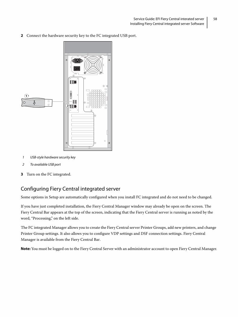
58Service Guide: EFI Fiery Central interated serverInstalling Fiery Central integrated server Software
2 Connect the hardware security key to the FC integrated USB port.
3 Turn on the FC integrated.
Configuring Fiery Central integrated server Some options in Setup are automatically configured when you install FC integrated and do not need to be changed.
If you have just completed installation, the Fiery Central Manager window may already be open on the screen. The Fiery Central Bar appears at the top of the screen, indicating that the Fiery Central server is running as noted by the word, “Processing,” on the left side.
The FC integrated Manager allows you to create the Fiery Central server Printer Groups, add new printers, and change Printer Group settings. It also allows you to configure VDP settings and DSF connection settings. Fiery Central Manager is available from the Fiery Central Bar.
Note: You must be logged on to the Fiery Central Server with an administrator account to open Fiery Central Manager.
1 USB-style hardware security key
2 To available USB port
1
2
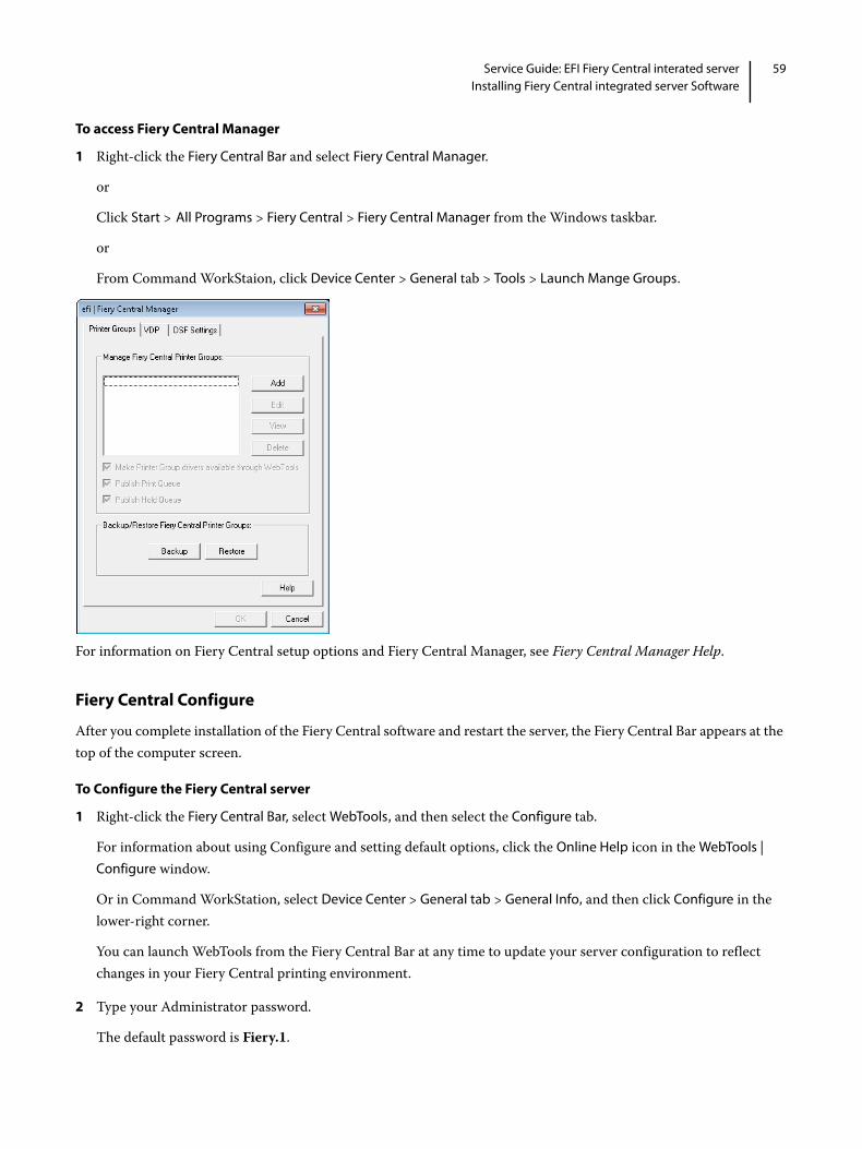
59Service Guide: EFI Fiery Central interated serverInstalling Fiery Central integrated server Software
To access Fiery Central Manager
1 Right-click the Fiery Central Bar and select Fiery Central Manager.
or
Click Start > All Programs > Fiery Central > Fiery Central Manager from the Windows taskbar.
or
From Command WorkStaion, click Device Center > General tab > Tools > Launch Mange Groups.
For information on Fiery Central setup options and Fiery Central Manager, see Fiery Central Manager Help.
Fiery Central Configure
After you complete installation of the Fiery Central software and restart the server, the Fiery Central Bar appears at the top of the computer screen.
To Configure the Fiery Central server
1 Right-click the Fiery Central Bar, select WebTools, and then select the Configure tab.
For information about using Configure and setting default options, click the Online Help icon in the WebTools |
Configure window.
Or in Command WorkStation, select Device Center > General tab > General Info, and then click Configure in the lower-right corner.
You can launch WebTools from the Fiery Central Bar at any time to update your server configuration to reflect changes in your Fiery Central printing environment.
2 Type your Administrator password.
The default password is Fiery.1.

60Service Guide: EFI Fiery Central interated serverInstalling Fiery Central integrated server Software
3 Click OK.

Troubleshooting
This chapter identifies the source of common problems that may occur with the FC integrated and suggests ways of correcting them.
Troubleshooting processProblems may occur in one of three areas:
• Inside the FC integrated
• Network connections between the FC integrated and the workstations or computers
This chapter does not attempt to provide troubleshooting information for attached computers such as Windows or Mac OS computers, printer/copiers, or extensive networks. Refer problems in these areas to the appropriate service departments and network administrators.
Preliminary on-site checkoutMost problems with the FC integrated are caused by loose board or cable connections. This section describes the quick checks that you can do to locate and fix obvious problems. It describes how to eliminate any problems with external connections to the back of the FC integrated, and then addresses checking internal board and cable connections. Check external and internal connections before replacing any components.
Note: Verify that the network is functioning, no unauthorized software or hardware is installed on the FC integrated, and no problems have occurred with a particular print job or application. The on-site administrator can help you verify these issues.
For problems that persist after you check the external and internal connections, this section provides a comprehensive list of internal and external checks that may help you fix the problem.
This section includes the following:
• “Checking external connections” on page 62
Describes the quick checks that you can do to make sure that the problem is not caused by a loose connection at the back of the FC integrated.
• “Checking internal components” on page 63
Describes the quick checks that you can do to make sure that the problem is not caused by a loose board or cable connection inside the FC integrated.
Important: When performing the service procedures described in this chapter, follow the precautions listed in page 6.

62Service Guide: EFI Fiery Central interated serverTroubleshooting
• “Inspecting the system” on page 63
Provides a more comprehensive checklist that you can use to check the FC integrated internally and externally. If your initial checks fail, complete this checklist before concluding that you need to replace a cable or component.
To troubleshoot problems that present specific symptoms, see “FC integrated error messages and condition” on page 68. Locate symptoms listed in the table to help you determine possible causes and steps to remedy them.
Checking external connections
Before removing the side and front panels of the FC integrated to check internal components, eliminate the most obvious sources of problems. Make sure that:
• All interface cables to the system are plugged into the proper connectors (see Figure 25).
• The power cable is plugged into the wall power outlet.
• The LED on the network port is blinking to indicate network activity.
Figure 25: FC integrated external cable connections
Front panel Connector panel
1 Power button 7 Power connector
2 Reset button 8 USB ports (x2) and network port (RJ-45)
3 Control panel 9 DVI port (VGA signal)
4 DVD drive 10 USB ports (x2)
1
2
3
4
5
6
7
8
9
1011

63Service Guide: EFI Fiery Central interated serverTroubleshooting
Checking internal components
To check the internal components, you must remove the side and front panels of the FC integrated.
To check internal components
1 Shut down, and then open the FC integrated (see page 18).
2 Inspect the inside of the FC integrated
Make sure that no foreign materials have been dropped into the chassis.
• Make sure that the DVD and hard disk drive data cables are connected to the correct SATA connectors on the motherboard (see Figure 5 on page 17):
• DVD drive power/data combination cable to motherboard connector SATA_6G_0
• Hard disk drive data cable to motherboard connector SATA_6G_1
• Look for obviously loose boards and reseat each board securely in its connector on the motherboard.
• Look for obviously loose cables and reseat each cable connector firmly.
• Make sure that each connector is properly aligned with its mating connector. If the pins are offset from each other, the affected board will not function properly.
3 Reassemble the FC integrated and verify its functionality (see page 53).
Inspecting the system
5 USB ports 11 USB ports (x2) and scan port (RJ-45)
6 Eject button
Note: Use the reset button only if the system is unresponsive to keyboard or mouse actions.
Important: Before you remove the FC integrated panels, be aware of the safety precautions that you should take when handling the FC integrated. Use standard ESD precautions when handling printed circuit boards and electronic components. To review the safety precautions, see page 6.
Important: Before you touch any components inside the FC integrated, attach a grounding strap to your wrist and discharge any static electricity on your body by touching a metal part of the FC integrated.
Important: If your initial checks of the cable and board connections do not fix the problem, you may need to inspect the system on a component-by-component basis, as described in “Table 1: Verifying the system.” A comprehensive inspection allows you to verify that each hardware component is properly installed and configured, and helps you avoid replacing expensive components unnecessarily.
Front panel Connector panel

64Service Guide: EFI Fiery Central interated serverTroubleshooting
If the system you are servicing does not meet a condition listed in Table 1, and it is not obvious what action(s) you should take to fix the problem (for example, if the system hangs before reaching Idle), locate the symptom in “FC integrated error messages and condition” on page 68 and perform the suggested action(s) for the condition.
Table 1: Verifying the system
Conditions to verify Part and additional page references
When the problem occurs, verify that: • Power cable is connected properly into the power outlet.• Chassis fans are operating.• Network link activity LED on RJ-45 connector is blinking.• All external cables required are present, in correct connectors,
and well-seated.• Cables, cable connectors, and mating connectors appear undamaged.
Connector panel external connectors, chassis fans, and power button, page 62 and page 63
If the problem occurs at power up or reboot, verify that:• Activity light on the control panel illuminates.• Display window lights up.• The system does not hang, and no error messages occur
before the systems reaches Idle.• After the system reaches Idle, the control panel buttons function.
Control panel, page 10
• All replaceable parts are:
• Present
• Properly aligned
• Installed securely
• Installed on the appropriate site
• The correct part for the system
• Properly configured, if configurable (such as hard disk drive jumper)
• Not visibly damaged
• Chassis and contents have not been tampered with.• Chassis does not contain any foreign objects.
Chassis
• Motherboard, including components and traces, appears undamaged, and no foreign objects are evident.
• CPU is present, well-seated, and appears undamaged.• CPU cooling assembly is well-aligned and firmly attached.• Each fan required (including fan cable) is well-positioned
(not upside down), installed in the correct connector, and appears undamaged.
• Boards required on the motherboard are present, well-seated, and in the correct slots.
• Each DIMM is well-seated.• Battery is installed.• BIOS is well seated.
Motherboard page 26
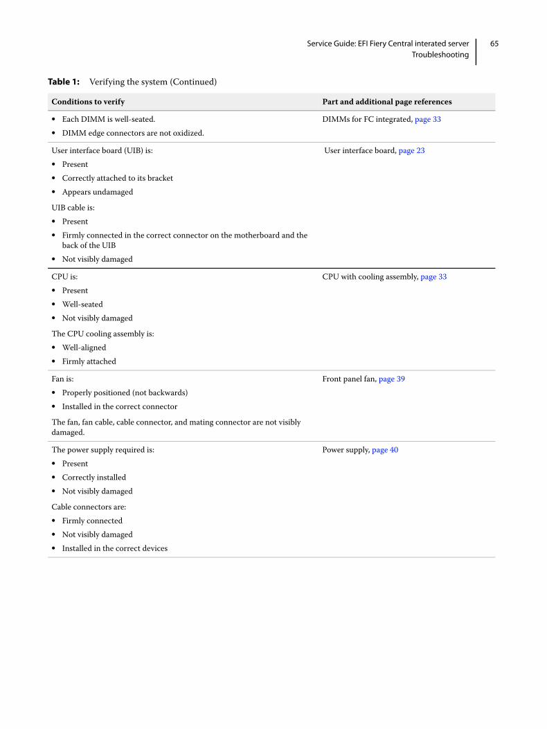
65Service Guide: EFI Fiery Central interated serverTroubleshooting
• Each DIMM is well-seated.• DIMM edge connectors are not oxidized.
DIMMs for FC integrated, page 33
User interface board (UIB) is:• Present• Correctly attached to its bracket• Appears undamaged
UIB cable is:• Present• Firmly connected in the correct connector on the motherboard and the
back of the UIB• Not visibly damaged
User interface board, page 23
CPU is:• Present• Well-seated• Not visibly damaged
The CPU cooling assembly is:• Well-aligned• Firmly attached
CPU with cooling assembly, page 33
Fan is:• Properly positioned (not backwards)• Installed in the correct connector
The fan, fan cable, cable connector, and mating connector are not visibly damaged.
Front panel fan, page 39
The power supply required is:• Present• Correctly installed• Not visibly damaged
Cable connectors are:• Firmly connected• Not visibly damaged• Installed in the correct devices
Power supply, page 40
Table 1: Verifying the system (Continued)
Conditions to verify Part and additional page references

66Service Guide: EFI Fiery Central interated serverTroubleshooting
Normal startup sequence
When you power on or reboot the FC integrated, the system runs a startup routine that takes about three minutes. If problems occur during startup and rebooting does not solve the problem, use Table 2 on page 68 to troubleshoot the system.
The hard disk drive required is:• Present• Correctly installed• Not visibly damaged• Jumpered as the master (primary) according to label
Hard disk drive data cable is:• Present• Firmly connected to motherboard connector SATA 2• Not visibly damaged
Hard disk drive, page 43
The drive required is:• Present• Correctly installed• Not visibly damaged• Jumpered as the master (secondary) according to label• Activity LED lights on power up
DVD drive SATA cable is: • Firmly connected to motherboard SATA 1• Not visibly damaged
DVD drive, page 52
Each cable required is:• Present• The correct type• Installed in the correct connector• Well-seated• Not visibly damaged (including connectors)
UIB cable, page 23
Hard disk drive data cable, page 43
DVD drive power and data combination cable, page 52
Power cable(s), page 40
If included in the system, the required mouse, monitor, and keyboard are present and appear undamaged. The mouse and keyboard are connected to the correct ports on the FC integrated connector panel.
The cables required are:• Present• Installed in the correct connector• Well-seated• Not visibly damaged (including connectors)
• Mouse (if applicable)• Monitor (if applicable)• Keyboard (if applicable)• Monitor power cord (not pictured)
Table 1: Verifying the system (Continued)
Conditions to verify Part and additional page references
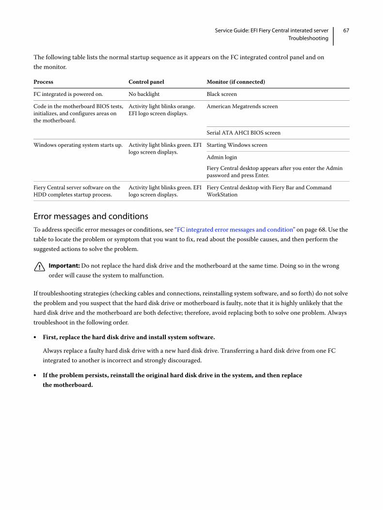
67Service Guide: EFI Fiery Central interated serverTroubleshooting
The following table lists the normal startup sequence as it appears on the FC integrated control panel and on the monitor.
Error messages and conditionsTo address specific error messages or conditions, see “FC integrated error messages and condition” on page 68. Use the table to locate the problem or symptom that you want to fix, read about the possible causes, and then perform the suggested actions to solve the problem.
If troubleshooting strategies (checking cables and connections, reinstalling system software, and so forth) do not solve the problem and you suspect that the hard disk drive or motherboard is faulty, note that it is highly unlikely that the hard disk drive and the motherboard are both defective; therefore, avoid replacing both to solve one problem. Always troubleshoot in the following order.
• First, replace the hard disk drive and install system software.
Always replace a faulty hard disk drive with a new hard disk drive. Transferring a hard disk drive from one FC integrated to another is incorrect and strongly discouraged.
• If the problem persists, reinstall the original hard disk drive in the system, and then replace the motherboard.
Process Control panel Monitor (if connected)
FC integrated is powered on. No backlight Black screen
Code in the motherboard BIOS tests, initializes, and configures areas on the motherboard.
Activity light blinks orange. EFI logo screen displays.
American Megatrends screen
Serial ATA AHCI BIOS screen
Windows operating system starts up. Activity light blinks green. EFI logo screen displays.
Starting Windows screen
Admin login
Fiery Central desktop appears after you enter the Admin password and press Enter.
Fiery Central server software on the HDD completes startup process.
Activity light blinks green. EFI logo screen displays.
Fiery Central desktop with Fiery Bar and Command WorkStation
Important: Do not replace the hard disk drive and the motherboard at the same time. Doing so in the wrong order will cause the system to malfunction.

68Service Guide: EFI Fiery Central interated serverTroubleshooting
If replacing a component does not correct the problem, make sure that you reinstall the old component back in the FC integrated.
Table 2: FC integrated error messages and condition
Symptom Possible cause Suggested action
Beep codes during Startup
1 beep No error. The FC integrated is starting up normally.
None
1 beep, followed by 3 beeps, followed by 3 beeps, followed by 1 beep
Missing, unmatched, incorrect,or faulty DIMMs
Check for missing, unmatched, incorrect or faulty DIMMs and reseat the DIMMs to remove any oxidation on the connector (see page 33).
Startup
FC integrated does not start and the control panel is black.
Note: If the Activity light is solid orange while the control panel is black, the FC integrated is in Sleep Mode.
Possibly one of the following:• The FC integrated is powered off• Power cable is not plugged into
the power connector on the FC integrated connector panel, or into the wall power outlet
• The connector panel power switch is in the OFF position
• UIB cable is not connected to the motherboard, the user interface board, or both
• Faulty power cable• Faulty power supply (power supply
may not be supplying power to the motherboard)
• The CMOS jumper is not in the default position
• Faulty motherboard (motherboard power plane may not be supplying power to components)
1 Recheck all cables and connections.2 Make sure the connector panel power switch is in the
ON position (see page 18).3 Listen for the power supply fan and feel for air at the
back of the unit where the power supply is located.If air is not coming from the power supply fan, isolate a possible faulty power cable as follows:• Power on using a different power cable.• Install a new or “known good” power supply.
4 Check the connector panel fan vent and feel for air coming out of the back of the system. If air is coming out of the power supply fan vent but is not coming out of the connector panel fan vent, the motherboard may be faulty. You may need to replace the motherboard (see page 30).
5 Review the jumper section on page 39 and ensure that the jumper is in the default position.
Activity light status:Off.

69Service Guide: EFI Fiery Central interated serverTroubleshooting
Startup (continued)
FC integrated is getting power, but the control panel is black.
• UIB cable is not connected to the motherboard, the user interface board, or both
• Faulty UIB cable• Faulty user interface board
1 Recheck all cables and connections.2 Use a different UIB cable.3 If the problem persists and you have verified that the
power supply and motherboard are functioning properly as described earlier, replace the user interface board (see page 23).
Following installation of a new user interface board, the control panel remains blank, yet backlit, for more than five minutes.
System software requires an additional reboot to synchronize with the firmware on the new user interface board.
Wait five minutes, power off using the power button, wait 10 seconds, and then press the power button to power on again.
NOT following installation of a new user interface board, system stops responding at this screen:
Possibly one of the following:• Faulty BIOS• Faulty motherboard
1 Recheck all cables and connections.2 Reboot the FC integrated.3 If the problem persists, replace the motherboard (see
page 30).
System stops responding at this screen:
Problem with the Fiery application. 1 Recheck all cables and connections.2 Reboot the FC integrated.3 If the problem persists, reinstall system software (see
page 55).
Table 2: FC integrated error messages and condition (Continued)
Symptom Possible cause Suggested action
Activity light status:Off.
Activity light status:N/A.
Activity light status:Off.
S T A R T I N G U P. . .
Activity light status:Blinking green.

70Service Guide: EFI Fiery Central interated serverTroubleshooting
Startup (continued)
Control panel screen and Activity light appear as follows:
Possibly one of the following:• Wrong, missing, incorrectly
connected, or faulty DIMM(s)• Faulty motherboard
1 Recheck all cables and connections.2 Reboot the FC integrated.3 If the problem persists, verify that the DIMMs are
installed. DIMMs must be installed in matching pairs in alternating sockets. Check for incorrect type, wrong capacity, missing, or faulty DIMM(s). Reseat the DIMM(s) to remove any oxidation on the connector (see page 33).
4 If the problem persists, you may need to replace the motherboard (see page 30).
Control panel screen and Activity light appear as follows:
Possibly one of the following:• Faulty disk in the DVD drive• Faulty motherboard
1 Reboot the FC integrated.2 If the problem occurs when you are installing software
from bootable media (DVD or CD), the media may be damaged. Try another DVD or CD.
3 If the problem persists, replace the motherboard (see page 30).
Table 2: FC integrated error messages and condition (Continued)
Symptom Possible cause Suggested action
Activity light status:Off, then solid red.
S T A R T I N G U P. . .
Activity light status:Blinking orange,then solid red.

71Service Guide: EFI Fiery Central interated serverTroubleshooting
Startup (continued)
Control panel screen and Activity light appear as follows:
Problem with the Windows operating system.
1 Recheck all cables and connections.2 Reboot the FC integrated.3 If the problem persists, reinstall system software (see
page 55).
Activity light status progresses from solid green to solid red.
Possibly one of the following:• Problem with system software• Print job is corrupt or too large• Faulty UIB cable• CPU overheated• Faulty motherboard
1 If you suspect that the problem may be caused by a print job, try printing a different job.
2 Recheck all cables and connections.3 Reboot the FC integrated and check whether the CPU
cooling assembly fan is operating. If the fan is properly connected to the motherboard but does not operate, replace the cooling assembly.
4 If the problem persists, reinstall system software (see page 55).
5 If the problem persists, try connecting another UIB cable (see Figure 5 on page 17).
6 If the problem persists, replace the motherboard (see page 30).
Control panel functions
FC integrated is getting power, the control panel is not black, but the buttons on the control panel do not function during the installation.
Possibly one of the following:• Faulty user interface board
1 Recheck all cables and connections.2 Reboot the FC integrated.3 If the problem persists, reinstall system software (see
page 55).4 If the problem persists, replace the user interface board
(see page 23).
DVD drive
DVD drive is not responding, cannot be located, or the disk will not eject.
Possibly one of the following:• A disk is stuck in the DVD drive• Cable connections to the DVD
drive are loose or data cable is faulty
• DVD drive is faulty• Motherboard is faulty
1 Press the eject button below the DVD slot on the front of the FC integrated.
2 If the problem persists, check the cable connections to the DVD drive (see Figure 5 on page 17).
3 If the problem persists, you may need to replace the DVD drive (see page 52).
4 If the problem persists, you may need to replace the motherboard (see page 30).
Table 2: FC integrated error messages and condition (Continued)
Symptom Possible cause Suggested action
S T A R T I N G U P. . .
Activity light status:Blinking green, then solid red.
Activity light status:Solid green, then solired.

72Service Guide: EFI Fiery Central interated serverTroubleshooting
System performance
System performs slowly and/or hangs periodically.
Possibly one of the following:• Board or cable connections are
loose or faulty• System software is corrupted• Missing or faulty DIMM(s)• CPU is overheated or faulty• CMOS settings need to be reset or
are corrupted• Motherboard is faulty
1 Recheck all cables and connections.2 Make sure that the CPU is firmly seated in its socket
and that the fan cable is connected to the motherboard. 3 If the problem persists, reinstall the system software
(see page 55).4 Check for missing or faulty DIMM and reseat the
DIMM to remove any oxidation on the connector (see page 33).
5 If the problem persists, you may need to replace the motherboard (see page 30).
Clock is slow. • Missing or dead battery on the motherboard
Replace the battery on the motherboard and update the time in the Windows Control Panel (if a monitor is connected), Command WorkStation, or WebTools.
The FC integrated hangs during the user software installation segment.
Possibly one of the following:• The time and date need to be
configured in the FC integrated BIOS. (If the battery was removed from the FC integrated motherboard during service and the time and date were not configured in Setup afterward, the FC integrated will hang during the user software installation segment.)
• User Software DVD is corrupted• The DVD drive is faulty• The hard disk drive is faulty
1 Set the time and date in the BIOS:• Power off the FC integrated and remove the User
Software DVD when it ejects.• If not already connected, connect a keyboard and a
monitor to the FC integrated.• Power on the FC integrated and immediately press F2
repeatedly to start the BIOS setup utility.• Configure the time and date. (To navigate, use the tab
key and the -/+ keys). • Save changes and exit (F10).• When the FC integrated reaches Idle, power off and
then begin a full software installation again, starting with the System Software DVD (see page 55).
2 If the problem persists, obtain another User Software DVD and begin software installation again starting with the System Software DVD (see page 55).
3 If the problem persists, you may need to replace the DVD drive (see page 52).If replacing the DVD drive does not correct the problem, reinstall the old DVD drive in the system.
4 If the problem persists, replace the hard disk drive (see page 43).If replacing the hard disk drive does not correct the problem, reinstall the old hard disk drive in the system.
Table 2: FC integrated error messages and condition (Continued)
Symptom Possible cause Suggested action

73Service Guide: EFI Fiery Central interated serverTroubleshooting
Network
If you suspect a network problem, keep in mind the following:• If the FC integrated does not appear in the list of printers on the network, another device on the network may have been
assigned the same Ethernet hardware address. • Conflicting network settings may have been configured in Setup and on the customer’s workstation.• Application-specific printing errors may be caused by missing or incorrectly placed printer description files.• System software may be corrupted.
Unable to connect to the network, or the green LED on the RJ-45 network port is not lit.
Possibly one of the following:• Network cable is connected to the
wrong RJ-45 port• No cable/wrong type of cable is
connected to the network port• Network cable or connection is
faulty• Network is faulty• If the FC integrated requires a static
IP address (for example, in a non-DHCP network environment), it may need to be reconfigured. A static IP address is deleted when system software is reinstalled.
• System software is corrupted• Network interface on the FC
integrated motherboard is faulty
1 If the problem persists, have the network administrator check Network Setup. To configure a static IP address (if applicable for the customer site), work with the network administrator as described in the Configure Help.
2 If the problem persists, make sure that the network administrator has checked other devices on the network.If other devices are not functioning, the problem may be with the network.
3 If the problem persists, reinstall the system software (see page 55).Corrupt system software may cause the system to hang.
4 If the rest of the network is functioning properly and the problem persists, replace the motherboard (see page 30).
Table 2: FC integrated error messages and condition (Continued)
Symptom Possible cause Suggested action

74Service Guide: EFI Fiery Central interated serverTroubleshooting
Network (continued)
System starts up slowly then displays one or more DHCP error messages on the control panel.
Possibly one of the following:• Network cable is connected to the
wrong RJ-45 port• No cable/wrong type of cable is
connected to the network port• Network cable or connection is
faulty• Network is faulty• System searches for a nonexistent
DHCP server because DHCP is enabled by default on the FC integrated, but the customer’s network is not using DHCP
• Ethernet interface on the FC integrated motherboard is faulty
• System software is corrupted
1 If the problem persists, ask the network administrator to check Network Setup. To configure a static IP address (if applicable for the customer site, as in a non-DHCP environment), work with the network administrator as described in the Configure Help.
2 If the problem persists, ask the network administrator to check other devices on the network.If other devices are not functioning, the problem may be with the network.
3 If the problem persists, reinstall system software(see page 55).Corrupt system software may cause the system to hang.
4 If the rest of the network is functioning properly and the problem persists, replace the motherboard (see page 30).
Table 2: FC integrated error messages and condition (Continued)
Symptom Possible cause Suggested action

Specifications
This section provides an overview of the Fiery print controller features, specifications, and safety certifications.
Hardware features
• Intel i5-4570S quad core 2.9GHz CPU (up to 3.6 GHz with Turbo Boost enabled)
• Memory: 4GB (2 x 2GB)
• An RJ-45 connector for 10BaseT/100BaseTX/1000BaseT Mbs connectivity over twisted pair cable (upper port)
• 1TB hard disk drive standard
• Built-in DVD drive
Physical specifications
• Operating Environment:
• Temperature: +5°C to +40°C
• Relative Humidity: 10%-85% (non-condensing)
• Power Supply Rating: 100-240V, 50-60Hz, 6A
• Power Supply Voltage Input: 100-240V @ 50-60Hz
• Power Supply Current Input: 100V @ 6A Max.; 240V @ 3A Max.
• Rated Power Consumption: 350W
• Dimensions (Height x Depth x Width): 48.5 cm (19.1 in.) x 48.3 cm (19.0 in.) x 21.5 cm (8.5 in.)
• Weight: 19.7 kg (43.4 lb.)
Networking and connectivity
• Supports AppleTalk and TCP/IP protocols simultaneously.
• Supports EtherTalk Phase 2 (allows users to print from a Mac OS computer to the FC integrated using the AppleTalk network protocol over an Ethernet network).
Safety and emissions compliance
The FC integrated has been certified to meet or surpass the following government standards:
Safety approvals
• IEC 60950-1:2005 (Second Edition) + Am 1:2009 + Am2:2013

76Service Guide: EFI Fiery Central interated serverSpecifications
• UL 60950-1:2007 R10.14 (TUV NRTL)
• CAN/CSA C22.2 No. 60950-1:2007 +A1:2011 +A2:2014 (TUV NRTL)
• GS Mark by TUV, EN60950-1:2006/A11:2009/A1:2010/A12:2011/A2:2013
EMI/EMC approvals
• FCC Title 47, Part 15 Subpart B, Class A
• ICES-003, Issue 5, August 2012, Class A
• EN55022:2010 (EU) Class A
• C-TICK mark (Australia and New Zealand)- Class A
• EN610003-2: 2006 Plus A1:2009&A2:2009 (EU)
• EN610003-3: 2008 (EU)
• EN55024:2010 (EU)

Servicing the Fiery Central integrated server with furniture
This chapter describes how to remove the FC integrated from the furniture in order to access internal components for service.
ProceduresIf the FC integrated is installed in the optional furniture, you must remove it from the furniture before performing most service procedures.
Figure 26: FC integrated installed on the furniture
Removing the FC integrated from the furniture
1 Monitor
2 Monitor pole
3 FC integrated
4 Table top
5 Stand
6 Drawer
Warning: Never lift the FC integrated by grasping the top panel. The top panel does not support the weight of the system.
1
2
3
4
5
6

78Service Guide: EFI Fiery Central interated serverServicing the Fiery Central integrated server with furniture
1 Make sure that the FC integrated is shut down and that all the cables are removed from the back of the FC integrated.
2 Remove the cable cover and disconnect the two monitor cables (power and video):
• Power from the back of the monitor and from the wall outlet
• Video from the back of the monitor and from the back of the FC integrated
1 Power cable
2 Cable cover
3 Video cable
1
2
3

79Service Guide: EFI Fiery Central interated serverServicing the Fiery Central integrated server with furniture
3 Remove the thumbscrews that attach the FC integrated stability bracket to the stand.
4 Lift the bracket and gently pull the FC integrated away from the table top.
Make sure to pull the FC integrated out just enough so that the front panel of the FC integrated is aligned with the back edge of the table top.
1 Thumbscrews
2 Stability bracket
1
2

80Service Guide: EFI Fiery Central interated serverServicing the Fiery Central integrated server with furniture
5 Remove the FC integrated left side panel (two screws) so that you can access the monitor pole tightening mechanism.
1 Monitor pole tightening mechanism
2 Left side panel
1
2

81Service Guide: EFI Fiery Central interated serverServicing the Fiery Central integrated server with furniture
6 Use the allen key to loosen the screw that secures the monitor pole to the FC integrated.
The allen key should be stored in the side drawer of the furniture.
7 Holding the monitor pole, gently lift the monitor pole assembly up and out of the FC integrated monitor mount.
8 Continue servicing the Fiery controller.
Replacing the FC integrated in the furniture
1 Make sure that the left side panel is removed from the FC integrated.
1 Allen key
1 Monitor pole
1
1

82Service Guide: EFI Fiery Central interated serverServicing the Fiery Central integrated server with furniture
2 Place the FC integrated upright on the furniture stand. Slide the FC integrated forward just until its front panel is aligned with the back edge of the table top.
Use the handle on the stability bracket to lift the rear of the FC integrated and slide it forward.
3 Route the monitor cables (power and video) into the cutout in the back of the top panel. Pull each cable out of the cutout in the top panel.
1 Video cable
2 Power cable
3 Top panel
4 Top cutout
5 Back cutout
12
3
4
5

83Service Guide: EFI Fiery Central interated serverServicing the Fiery Central integrated server with furniture
4 Lift up the pole assembly and insert the pole into the top of the FC integrated so that it is inside the monitor mount. Tighten the assembly into place using the allen key.
5 Replace the left side panel on the FC integrated with the screws that you removed earlier.
1 Tighten the monitor assembly
1

84Service Guide: EFI Fiery Central interated serverServicing the Fiery Central integrated server with furniture
6 Use the handle on the stability bracket to lift the rear of the FC integrated. Slide the FC integrated all the way forward into the stand. Lock the FC integrated into place with the two thumbscrews that you removed earlier.
7 Connect the two monitor cables (power and video):
• Power to the back of the monitor and to the wall outlet
• Video to the back of the monitor and to the back of the FC integrated
1 Power cable
2 Video cable
3 Stability bracket (lock into place with two thumbscrews)
1
2
3

85Service Guide: EFI Fiery Central interated serverServicing the Fiery Central integrated server with furniture
8 Replace the cable cover over the cables and monitor pole.
9 Replace the allen key in the furniture drawer and continue reassembling the Fiery print controller.
1 Cable cover
1

AAC connector 62activity light 23, 68, 69, 70AppleTalk 75
Bback panel connectors 62Balance module
install 55battery 37, 72boards
motherboard 26user interface 23
bracketHDD 45, 48
buttonsdown 10, 11, 23line selection 11line selection (move left/right) 10, 23menu 11, 23UIB, replacing 25up 10, 11, 23
Ccables
checking 62CPU fan 35, 37DVD drive 17, 48front panel fan 39front panel USB ports 48, 49, 52HDD data 17, 45, 48HDD power 45, 48power and reset buttons 48, 49, 52power supply 40printer interface 62speaker 48, 49, 52UIB 17
checklist for service calls 53clearing the CMOS 39clock 72closing the system 54CMOS 39
troubleshooting start up problems 68component sled 48, 50, 52components
checking 63exploded view of 16
configuration, see setupconfiguring a static IP address 73configuring Fiery Central 59connections, checking 62, 63
connectorsback panel 62network 62power, AC 62printer interface 62USB ports (dongle) 62
Control Panelbuttons 11
control panelactivity light 69, 70buttons 23display window 10using 10
cooling assemblyCPU 33, 35
covers, removing 19CPU 75
connecting the CPU fan power cable 37overview 33removing and replacing 35removing the cooling assembly from 34replacing the cooling assembly on 36
DDHCP network environment 73diagnostics, Ethernet address 73DIMMs
configuration 33, 75removing 33replacing 33
display window, control panel 10down button 10, 11, 23drives
DVD 52hard disk drive (HDD) 43, 48
DVD drive 48, 52power and data cables 17removing 52replacing 53
EEFI Fiery Central Bar
EFI Fiery Central Setup 59EFI Fiery Central License Manager 56EFI Fiery Central
licensing terms 56Ethernet
address 73exploded view
CPU and cooling assembly 33print server 16
Index

87Service Guide: EFI Fiery Central interated serverIndex
Ffan
CPU 33, 35front panel 39
ferriteinstalling on the front panel USB port cables 52installing on the power supply 43removing from the front panel USB port cables 49removing from the power supply 41
Font listprinting prior to HDD replacement 45
front panel 14, 62fan 39layout 10removing 20
front panel USB ports 48Functions menu
Shut Down 11, 18
Hhard disk drive (HDD) 43, 47, 48
bracket 45, 48capacity 75caution about replacing 47, 67data cable 45, 48description 43mounting screws 47, 48proper handling 44removing 45replacing 47
hardware security key 57heatsink, CPU 33, 35
Iinstall
Fiery Central software 55hardware security key 57
IP address, static 73
Jjumpers 39
LLCD 10, 23line selection buttons 10, 11, 23
Mmemory
configuration 33, 75removing 33replacing 33
menubutton 11
menu button 23motherboard
battery 37cautions about replacing 30description 26DIMMs 33removing 26, 29replacing 30verifying in Service Mode 30
move left/right buttons 23
Nnetwork
supported types 75normal startup sequence 66
Oopening the system 19
Ppanels, removing 19, 20power
AC cable 62AC connector 62CPU fan 35, 37DVD drive 53front panel fan 39HDD 48power and reset cables 17
power and reset buttons 48power supply
cables 40removing 40replacing 42voltages 12, 40, 75
Rreassembling the system 54reset and power buttons 11, 18Restart server 12reusable tie-wrap 41, 43
Sserver
setup see server setupservice calls
checklist 53Service Mode 30service procedures, overview 13setup 59
access 59license information 56
shutting down 11, 18side panels
removing 19replacing 19
slot assignments, motherboard 62

88Service Guide: EFI Fiery Central interated serverIndex
softwaresystem 30user 30
speakermotherboard connection 17removing 49, 52
specifications 75startup 12
normal sequence 66static IP address, configuring 73switch bank assembly 48, 53
removing 49replacing 51
system performance 72system software
do not install after installing a new motherboard 30
Tterminology 13thermal compound 31, 36tie-wrap, reusable 41, 43troubleshooting
beep codes during startup 68checking external connections 62checking internal connections 63control panel functions 71DVD drive 71error messages and conditions 67network 73normal startup sequence 66preliminary on-site checkout 61startup problems 68system performance 72
UUIB cable
routing diagram 17up button 10, 11, 23USB port 57USB ports 48, 62user interface board (UIB)
activity light 23buttons on 25description 23display window 23line selection buttons (move left/right buttons) 23menu button 23removing 24replacing 25up/down buttons 23
user softwaredo not install after installing a new motherboard 30troubleshooting problems during installation 72
Vverifying functionality 53voltages
checking 12, 40