effects of the magnetic dilution on the ferrimagnetic resonance of disordered heterostructures
TRANSCRIPT

Journal of Magnetism and Magnetic Materials 264 (2003) 86–94
Effects of the magnetic dilution on the ferrimagnetic resonanceof disordered heterostructures
Jean-Luc Mattei*, Marcel Le Floc’h
Laboratoire d’Electronique et des Syst"emes de T!el!ecommunications UMR CNRS 6616, BP 8099, 6 av. Le Gorgeu,
Brest Cedex 29285, France
Received 4 October 2002; received in revised form 20 January 2003
Abstract
This study deals with the noteworthy effects of inner demagnetizing effects on the ferrimagnetic resonance (FMR)
of disordered heterostructures, in particular, close to their percolation concentration (Cp) in magnetic material.
A recognized experimental fact is that the FMR increases with decreasing soft ferrite content in such composite
materials. We have undertaken a systematic experimental study of Ni1�xZnxFe2O4 composite materials, at the
low frequency range and at their gyroresonance. Our interpretation of the data, based on the Effective Medium
Theory, uses a reciprocity principle developed for heterostrucures. At concentrations below Cp magnetic gaps,
which originate from the magnetic dilution, may cause a cut-off of the magnetic flux-paths in the composite
medium, leading to inner demagnetizing effects that increase the magnetic anisotropy. Whereas above Cp; the topologyof the percolating cluster allows a magnetic flux path to be continuous throughout the material, here the inner
demagnetizing effects vanish, leading the FMR to be that of the bulk itself in the concentration range going from Cp to
unity.
r 2003 Elsevier Science B.V. All rights reserved.
PACS: 75.40.Cx; 75.50.Lk; 75.40.Gb
Keywords: Composite materials; Gyroresonance; Demagnetizing effects; Percolation; Reciprocity principle; Effective medium
1. Introduction
Ferrite composite materials find applications inthe microwave range. In the case of single-layerabsorbers made of ferrite composite materials, themaching frequency is expected to be controlled bychanging the ferrite content [1]. In microwave
devices such as tunable stop-band filters, or non-reciprocal devices (phase-shifters, circulators) [2–4]the gyromagnetic absorption is used, so that theabsorbed microwave power is strongly related totheir resonance frequency. However the operationscould be affected by non-uniform internal fields[2,3]. Numerous studies dealing with magneticheterostructures, which are constituted of avolume fraction C of magnetic soft particlesmatter (micro or nano sized) dispersed within anon-magnetic binder, have reported a pronounced
ARTICLE IN PRESS
*Corresponding author. Tel.: +33-2-98-01-62-91; fax: +33-
2-98-01-63-95.
E-mail address: [email protected] (J.-L. Mattei).
0304-8853/03/$ - see front matter r 2003 Elsevier Science B.V. All rights reserved.
doi:10.1016/S0304-8853(03)00143-4

increase of the measured ferro (ferri) magneticresonance (FMR) with decreasing ferrite contentin composites [1,6–11]. This paper presents arelation, which describes the particular behaviourof the resonance frequency of composite materials.Very recently, we have shown a way in which thevariations of the demagnetizing effects (both innerand outer) in disordered magnetic heterostructuresare ruled by the aggregation of the magneticinclusions in these materials [5]. A convergence ofevidences, obtained from several independentmethods (experimental, analytical and numerical),underlined the role played by the percolativephenomenon that takes place at the volumicconcentration Cp in magnetic material. Amongthe magnetic properties of soft magnetic materialsthat depend on demagnetizing effects, the FMR isprecisely known to be a very sensitive one. Arelationship established by Kittel shows that thecondition for the FMR of a uniformly magnetizedbulk material placed in the empty space dependsstrongly on its shape [12]. In this case this relationdescribes the demagnetizing effects coming fromouter demagnetizing fields only. But in the case ofcomposite media both inner and outer demagne-tizing effects may exist, depending on the value ofC [5]. So, we think that Kittel’s relation should notbe used in the case of heterostructures. Actually thecontinuity of the magnetic flux may be hinderedfor large enough amounts of the non-magneticbinder that coat the magnetic particles: when C
belongs to the range 0–Cp; magnetic gaps whichoriginate from the magnetic dilution cause a cut-off of the magnetic flux paths in the compositemedium. This leads in turn to a rise of themagnetic anisotropy and to the related innerdemagnetizing effects. For concentrations aboveCp; the topology of the percolative cluster allows amagnetic flux path to be continuous from one endof the material to the other end; the demagnetizingeffects depend mainly on the sample geometry.The aim of this study is to show that FMR incomposite materials is, for concentrations CoCp;mainly ruled by the variations of their innerdemagnetizing effects which are going togetherwith the variations of C. Whereas, for C > Cp; theFMRs’ values are set in by the external shape ofthe material.
2. Experiments
Soft magnetic powders (Ni1�xZnxFe2O4 ferrites)have been synthesized in our laboratory by a wetmethod [13]. This technique ensures a very highchemical purity for the resulting powders. Scan-nings by electron microscopy show regular sphe-rical-shaped particles, with sub-micronic diametersof about 0.1 mm. The composites samples wereconstituted by mixing soft magnetic with non-magnetic (resin) powders. Then they were shapedand pressed at room temperature in ring-shapedmolds, in order to avoid the macroscopic demag-netizing effects. The volume loading C in magneticmatter we are mainly interested in ranges betweenabout 10% and 51%. Higher concentrations inmagnetic matter are not desirable, and have beenavoided. Actually, the higher limit we reached,close to C=51%, corresponds roughly with themaximum filling fraction (Cf ¼ 50260%) of arandom packing of equal-sized particles [14]. Thehigh concentration range, which starts with thisfilling coefficient, cannot be reached unless highpressures are applied on the composite. Such atreatment, which bend out of shape the particles,will certainly lead to modify the physical origin ofthe magnetic permeability mi of the inclusions. Thismay be because the magnetization mechanism themagnetic powders are concerned with is primarilycontrolled by spin rotations, and this mechanismholds as long as particles are connected togetherthrough contact points, that is up to C ¼ Cf [15].Whereas to deform spherical particles in order toget a more dense medium would lead large grainboundaries to appear, and would eventuallyenhance this way (from contributions of multi-domain components) the initial permeability mi ofthe inclusions. However, some sample with highconcentrations (C close to 0.7) have been realized.
The ring-shaped samples were placed in order tofill an HP APC7 coaxial line, and their initialsusceptibility ðw� ¼ w0 � jw00Þ was obtained in the30–20GHz frequency band by using networkanalysers (HP 8753 and HP 8720), at roomtemperature. Several experimental results weobtained, including measurements on YIG-basedcomposites, have been already exposed [7]. Thecommon behaviour of the recorded variations of w0
ARTICLE IN PRESS
J.-L. Mattei, M.L. Floc’h / Journal of Magnetism and Magnetic Materials 264 (2003) 86–94 87

and w00 with the reduced frequency f =fR; and thestatic susceptibility w; is drawn in Fig. 1. Now wefocus on the frequency where w00 reaches itsmaximum value. We identify this particularfrequency fR to the magnetic resonance frequencyof the composite material. The observed shift ofthe frequency resonance fR with the volumeconcentration in magnetic material C is as shownin Fig. 2. Previous experiments, performed inother laboratories, argue in favour of this kindof behaviour for fR [1,6–11].
3. Background: description of the heterostructures
3.1. Decreasing inner demagnetizing effects and
enhanced recipocity at the percolation threshold
We consider an assembly of magnetic inclusionsdispersed in empty space. We would like toquantify, in a somewhat reliable and straightdescription, the intensity of the magnetic interac-tions between any two of the inclusions. Ob-viously, this must have something to do with thecontinuity of the magnetic flux paths inside thiscomposite medium. Focusing on one among themagnetic inclusions, we have demonstrated thatthe path followed by the magnetic flux density B
!
inside the medium can be linked to the innerdemagnetizing effects through the following rela-tion, where the tensors’ components are expressedin the particle frame (a ¼ x; y or z) [5]:
Na ¼ Aa � ð1� RÞ: ð1Þ
The Aa’s are the usual shape factors of theconsidered inclusion. They depend on the inclu-sion’s shape, and not on the magnetic properties ofits surrounding medium. Whereas the diagonalcomponents Na’s of the demagnetizing factor ofthe inclusion depend on the magnetic properties ofits surrounding medium [16], the reciprocity factorR, defined as the ratio
ðRÞ ¼Z
v2
~BB1 ~MM 2 dt� �. Z
v1
~BB2 ~MM 1 dt� �
quantifies the magnetic coupling between tworegions of volumes V1 and V2: We have demon-strated that a useful expression for R in the casewhere the magnetic inclusion (permeabilitymi ¼ 1þ wi) is embedded in a continuous magneticmedium (permeability me ¼ 1þ we) is R ¼miwe=mewi: The physical meaning for the (1� R)mutiplying term in Eq. (1) is that it would stemfrom the decrease in surface poles when meincreases. The variations of R with C are plottedon Fig. 3 (with Az ¼ 1=3). The value R ¼ 0 wouldmean that there are no magnetic interactionsbetween any two inclusions in the material (thiswould depict the situation in the low concentrationrange, where the magnetic correlation lengthis lower than the interinclusions length, whereas
ARTICLE IN PRESS
f/fR1
0
χ"
χ'
χ*
χ
Fig. 1. A schematic drawing for the complex susceptibility w�observed on Ni1�xZnxFe2O4 composite materials. At the lowest
frequencies, w� ¼ w:
0.2 0.4 0.6
C
f r/f
bulk
1
2
Ni1-xZnxFe2O4
x=0 x=0.3 x=0.5
0
Fig. 2. Reduced values of the experimental FMR measured on
Ni1�xZnxFe2O4 composite materials. For reasons, which are
detailed in the main text, values for C > 0:51; although
valuable, have not been exploited (except to show that the
FMR fbulk for the bulk arises as soon as C is closed to 0.6).
J.-L. Mattei, M.L. Floc’h / Journal of Magnetism and Magnetic Materials 264 (2003) 86–9488

R ¼ 1 means total influence between two giveninclusions: all the magnetic flux density linescoming from one inclusion reach the otherinclusion (this depicts the case of the highconcentration range, namely above the percolationthreshold). It can be seen that 0pRp1 means thatthe coupling strength is weak if RD0; and strong ifRD1: In the latter case, all the magnetic field linescreated by V1 go through V2; and vice versa.
3.2. The fictious shape factor
Mixing laws are often used to get the effectiveproperties of composite materials as a function ofthe intrinsic properties of their components. Thepredicted values are also strongly dependent onthe inclusions’ shape. The mixture to be describedis often assumed to be a somewhat idealizedmedium constituted of spherical inclusions. How-ever, we think that this a priori assumption couldnot suit well the actual materials, because the usualmanufacturing processes do not prevent particlesaggregation. Actually, during the powder mixingprocess, as well as during the following mixing ofmagnetic with non-magnetic parts, the individualparticles stick together to form complex chainsand clusters of various shapes. Then the questionarises how long it is right to assign for the
magnetic inclusions inside the composite shapefactors Aa ¼ 1=3: We believe that a variation of Aa
with C must be regarded at least as a possibility.The aim of this section is to provide an analytictool giving rise easily to the experimental values ofAa; in order to include some of the effects due tothe actual state of aggregation of the powderparticles.
Expression of the effective medium theory’s(EMT’s) approximation developed by Bruggeman[17] to randomly dispersed ellipsoids of identicalshapes, immersed in a non-magnetic matrix can bewritten as (see Appendix A)
Xa¼x;y;z
C
3
ðmi � meÞð1� AaÞme þ ðmi � meÞAa
� ��
þð1� CÞ
3
ðmi � meÞð1� AaÞme þ ð1� meÞAa
� ��¼ 0; ð2Þ
where mi denotes the permeability of the magneticmaterial (volume concentration C) and me; that ofthe effective medium. Since magnetic grains arethemselves materials made of clusters of severalrandomly oriented crystallites, the assumption isnow made that the actual samples are macro-scopically isotropic. This consideration allowssimplify Eq. (2). Actually, under only slightlyrestrictive conditions (see Appendix A), thetensorial Eq. (2) can be written in the followingmore versatile scalar form, and used so:
ð1� AÞ w2e þ ½1þ ðA � CÞwe � C we� ¼ 0: ð3Þ
There are really no compelling assumptionsrequired to write Eq. (2) under the form ofEq. (3). But once written under this scalar form,it turns out that the mixing rule expressed byEq. (A.1) can be understood as, in a sense, dealingwith a fictious shape factor A: In fact, A is linkedto the magnetic properties of the inclusionsconstituting the mixture, and also to their geome-trical aspects, through the relation
A ¼2þ 3Azð1� AzÞ d6þ ð1þ 3AzÞ d
; ð4aÞ
where d ¼ wi=ð1þ weÞ: ð4bÞ
It can be underlined that the internal fields inEMT explicitly depend on the shape factors Aa of
ARTICLE IN PRESS
0
0.1
0.2
0.3
0.4
0.5
0.6
0.7
0.8
0.9
1
0 0.2 0.4 0.6 0.8 1C
reci
pro
city
fac
tor
R
χi = 20
χi = infinite
Fig. 3. Reciprocity factor of a spherical particle (Az ¼ 1=3)embedded in a disordered composite medium whose equivalent
permeability is described by Bruggeman’s EMT (C is the
magnetic load fraction). The sensitivity to C above the
percolation threshold reflects the magnetic poles fading. The
magnetic permeability of the particles has been taken equal to
20 or to infinity.
J.-L. Mattei, M.L. Floc’h / Journal of Magnetism and Magnetic Materials 264 (2003) 86–94 89

the inclusions, and not at all on their demagnetiz-ing factors Na: It should be remarked, also, thatthe values taken by A are independent of theaverage isotropy of the material, otherwise onewould get A ¼ 1=3 whatever the particles shapedistribution could be. (This is because Brugge-man’s EMT is based on an average of the fields, noaveraging of the Aa’s is done.) We have usedEqs. (3) and (4) as tools for an easier determina-tion of the experimental variations of the factor A
with the magnetic loading C; from which thevariations of Az can be deduced.
4. Interpretation of experimental data
The fictitious shape factor and the innerdemagnetizing factors are determined, at first, inthe low frequency range. The FMR is calculated inthe second stage.
4.1. The low frequency range: determination of
inner demagnetizing factors Nz
Below f ¼ 50MHz magnetic losses are very low,and we get w ¼ w0: A typical variation of w0 with themagnetic fraction C is shown in Fig. 4. A similarbehaviour is obtained for the three-ferrite compo-sites studied. The scalar EMT (Eq. (3), where theequivalent permeability me has been identified tothe experimental permeability m suits these experi-mental results for the values of the shape factor A
that are presented in Fig. 5. These fits lead to theintrinsic susceptibilities wi of the variousNi1�xZnxFe2O4 powders we used (x ¼ 0; 0:3; 0:5give wi ¼ 4; 11, 15, respectively). These valuesfound for wi are those usually assigned to arotational mechanism of magnetization in thecompounds investigated [18].
In the whole explored concentration range,going from C ¼ 0:18 to 0:51; the most completesuperposition of the three curves is noticed.
Starting from C ¼ 18% and A ¼ 0:08; the valueof the fictious shape factor rapidly increases until itreaches the value of A ¼ 0:31 when C ¼ 40%:From C ¼ 40% to 51%, A increases more slowlyuntil it reaches the value of 1/3. (This behaviour ofA when C varies was already interpreted by usinga statistical approach of the inclusions’ shapedistribution in the composite medium [19]). Theassociated values of the shape factor Az can thenbe extracted with the help of Eq. (4). The resultsare given in Fig. 6. The accuracy of the experi-mental Az is not so satisfactory in the lowest C
range explored compared to that in the highest C
range. However, fairly it can be set that Az ¼ 1=3just above C ¼ 0 (isolated particles). Then, thedemagnetizing factor Nz of the inclusions and thereciprocity factor of the medium can be extractedfrom these experimental results on Az; using R ¼miwe=mewi and Eq. (1). Nz and R are presented inFig. 7.
A percolation threshold can be identified atthe concentration point above which Nz showsa noticeable decrease, i.e., Cp lies closely to
ARTICLE IN PRESS
0
4
8
12
χ
Ni0.7Zn0.3Fe2O4
(100 nm)
0 0.2 0.60.4C
χi
Fig. 4. An example of the experimentally determined static
susceptibility for Ni0.7Zn0.3Fe2O4-based composites materials.
Extrapolation of the recorded data to C ¼ 1 is very close to the
value of the rotational susceptibility for this material.
0.00
0.05
0.10
0.15
0.20
0.25
0.30
0 0.2 0.4 0.6 0.8 1
C
Fic
tio
us
shap
e fa
cto
r A
Fig. 5. The fictious shape factor, extracted from the measured
static susceptibilities of the composite materials, in using Eq. (3)
(symbols signification: grey: x ¼ 1; black: x ¼ 0:3; white:
x ¼ 0:5).
J.-L. Mattei, M.L. Floc’h / Journal of Magnetism and Magnetic Materials 264 (2003) 86–9490

C ¼ 0:2: This concentration value is, significantly,quite the same as those corresponding to the sharpincrease of the macroscopic demagnetizing factorof rod-shaped heterostructures (see Fig. (1) inRef. [5]).
In the present case, two changes can berecognized in the slope of R; the first one arisesat CD0:2; and the second one at CD0:35: CD0:2
would correspond to the threshold of aggregationof particles into a percolative cluster, from whichstarts a phenomenon of magnetic interactions atthe scale of the sample. Above C ¼ 0:35; most ofthe magnetic inclusions are concerned with thatphenomenon.
4.2. Experimental gyroresonance in actual
composite bodies: an insight into an effect of the
reciprocity phenomenon in these materials
We propose in this section an interpretation ofthe gyroresonance measured on soft compositematerials, which includes explicitly the role playedon fR by the reciprocity factor through thedemagnetization in magnetic heterostructures.When the dynamic properties of the magnetizationhave to be considered one would expect div ~MMa0;so that additional magnetic poles appear inside thevolume of the sample. As a consequence, incomparison with the static problem, the situationmay become complicated to be analytically trea-ted. Nevertheless, to assume div ~MM ¼ 0; as we do,is an approximation close to actual situations [20].
We consider an ellipsoid in the saturatedmagnetic state (with the magnetization ~MM s), andcharacterized by demagnetization factors N0
a wherethe subscript ‘‘0’’ indicates that the ellipsoid is
placed in the empty space (in fact, N0a ¼ Aa in this
situation). The Kittel equation for the resonancefrequency of such a bulk body can be written as
fk ¼ffiffiffiffiffiffiffiffiffiffiffiffiffiffiffiffiffiffiffiffiffiffiffiffiffiffiffiffiffiffiffiffiffiffiffiffif0 þ fMðN0
y � N0z Þ
q
�ffiffiffiffiffiffiffiffiffiffiffiffiffiffiffiffiffiffiffiffiffiffiffiffiffiffiffiffiffiffiffiffiffiffiffiffif0 þ fMðN0
y � N0z Þ
q� ð1þ a2Þ�1=2: ð5Þ
In this relation, f0 ¼ gH0=2p (g ¼ 35:12�10�3 MHz/Am�1 and H
!0 is the crystalline aniso-
tropy field responsible for the magnetic momentsalignment. Its direction defines the z-axis. Noexternal static field is considered), fM ¼ gMs=2pand a is the damping coefficient. (This coefficient isnot given in the original derivation of Eq. (5)because the damping was not considered, butit appears by solving the equation of the dynamicmotion of the magnetization in unboundedmaterial [21].)
ARTICLE IN PRESS
0
0.05
0.1
0.15
0.2
0.25
0.3
0.35
0.4
0 0.2 0.4 0.6 0.8 1
C
Exp
erim
enta
l sh
ape
fact
or
Az
of
the
incl
usi
on
s
Fig. 6. The shape factor Az calculated in using both Eq. (4) and
the experimental data of Fig. 5. Signification of the symbols
same as in Fig. 5.
0
0.05
0.1
0.15
0.2
0.25
0.3
0.35
0.4
0 0.2 0.4 0.6 0.8 1C
Inn
er d
emag
net
izin
g f
acto
r N
z (i
ncl
usi
on
s)
Exp
erim
enta
l rec
ipro
city
fac
tor
R1
1/2
Fig. 7. The reciprocity factor R (triangles), which account for
the intensity of the magnetic flux linkage between the magnetic
inclusions, increases as the inner demagnetizing factor Nz
(circles) of these inclusions decreases. The following values can
be conjectured: for C ¼ 0: Nz ¼ 1=3 and R ¼ 0; for C ¼ 1:
Nz ¼ 0 and R ¼ 1: The somewhat sharp increase of R above
C ¼ 0:2 is related to the aggregation of the magnetic inclusions
into a percolative cluster at this concentration. (The colors of
the symbols have the same signification as in Fig. 5.) Dashed
lines are guidelines.
J.-L. Mattei, M.L. Floc’h / Journal of Magnetism and Magnetic Materials 264 (2003) 86–94 91

(The static expressions of the fields used in theEMT requires the scale of the inclusions to besmaller than the wavelength in the material. Thisrequirement is not in this study because in theexplored frequency range the lower wavelength inthe material is typically about 0.05m, that is abouttwice the lowest sample dimension.) According toBruggeman’s EMT, the description of the actualcomposite material consists in ellipsoidal particlesincluded in the effective medium. The effects of themagnetic dipolar interactions in the actual mediumare taken into account by using the self-consistentfield calculation method. This is why the magneticinclusions, when they are immersed in the effectivemedium, are considered to be not interactingtogether. In order to make Eq. (5) suitable to beapplied to the FMR of composite materials, thedemagnetizing factor Na (as it is given by Eq. (1))has been substituted by N0
a : Therefore, theproposed extension of the Kittel expression,initially written for a saturated ellipsoid, to thefrequency resonance fR of a disordered hetero-structure formed by the assembly of saturatedellipsoids randomly dispersed in a non-magneticmatrix, is written as follows (the assumption ofellipsoidal shaped inclusions allows to write N0
x ¼N0
y in Eq. (5)):
fR ¼ff0 þ fM � ðN0y � N0
z Þ
� ð1� RÞg � ð1þ a2Þ�1=2 ¼ 0 ð6Þ
which underlines the major role taken by thereciprocity factor R:
Our experimental data are very satisfactorilymatched by Eq. (6) (see Fig. 8). The magneticparameters for Ni1�xZnxFe2O4 found used in theliterature are the following [18] x ¼ 0: Ms ¼ 267 kA/m, H0 ¼ 50:7 kA/m, x ¼ 0:3: Ms ¼ 410 kA/m,H0 ¼ 21:3 kA/m, x ¼ 0:5: Ms ¼ 450 kA/m, H0 ¼12:2 kA/m; the common value used for the dampingparameter was a ¼ 0:3:
5. Conclusion
We have performed experiments that clearlyshow that the FMR of soft magnetic heterostruc-tures increases while decreasing the magnetic
material content C: An increase of the couplingbetween the soft magnetic inclusions reducessignificantly their demagnetizing energy, hencetheir total magnetic anisotropy energy. To quanti-fy the magnetic coupling intensity between aninclusion and its surrounding medium, weintroduced the quantity that we called recipro-city factor, denoted R: So, the reciprocity factorshows a pronounced sensitivity to magneticpoles’ variations and, therefore, to inner demag-netizing effects. Experiments have shown that ifCo0:35; the stronger the inner demagne-tizing factor, the smaller the reciprocity factor.Whereas, if C > 0:35 the inner demagnetizingeffects are very feeble and hence R is close to itsmaximum value. (That behaviour is connected tothe formation of a percolating magnetic cluster.)Then, starting from the basics of Kittel’s relationfor bulk materials, we have shown that the changesin the magnetic anisotropy induced by themagnetic dilution cause the observed sensitivityof FRM to the concentration C in magneticmaterial. The expression we suggest for the FRMcould be used as a predictive law. We think alsothat the reciprocity factor can be used as a newtool for the examination of those properties of softmagnetic heterostructures that are concerned withinner demagnetizing effects.
ARTICLE IN PRESS
0
500
1000
1500
2000
2500
3000
0 0.2 0.4 0.6 0.8 1
C
fr (
MH
z) o
f N
i 1-xZ
nxF
e 2O4
com
po
site
s x=0
x=0.3
x=0.5
Fig. 8. The closed symbols are the measured FMR, and the
open symbols are their computed variations (Eq. (6)). Data
corresponding to C > 0:51 have not been fitted for reasons
detailed in the main text. Bulk values have been calculated from
literature data (see main text). Materials with a magnetic load
higher than about 0.3 show the same resonance frequency as the
bulk itself.
J.-L. Mattei, M.L. Floc’h / Journal of Magnetism and Magnetic Materials 264 (2003) 86–9492
Appendix A
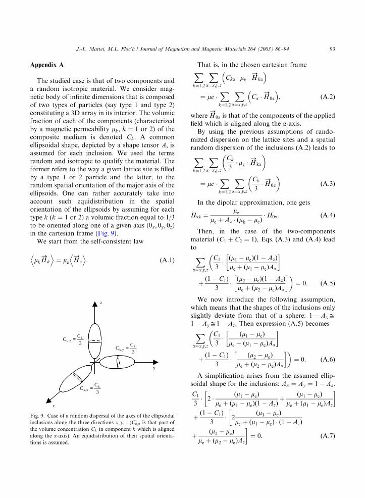
The studied case is that of two components anda random isotropic material. We consider mag-netic body of infinite dimensions that is composedof two types of particles (say type 1 and type 2)constituting a 3D array in its interior. The volumicfraction of each of the components (characterizedby a magnetic permeability mk; k ¼ 1 or 2) of thecomposite medium is denoted Ck: A commonellipsoidal shape, depicted by a shape tensor A; isassumed for each inclusion. We used the termsrandom and isotropic to qualify the material. Theformer refers to the way a given lattice site is filledby a type 1 or 2 particle and the latter, to therandom spatial orientation of the major axis of theellipsoids. One can rather accurately take intoaccount such equidistribution in the spatialorientation of the ellipsoids by assuming for eachtype k (k ¼ 1 or 2) a volumic fraction equal to 1/3to be oriented along one of a given axis (0x; 0y; 0z)in the cartesian frame (Fig. 9).
We start from the self-consistent law
mkH!
k
D E¼ me H
!e
D E: ðA:1Þ
That is, in the chosen cartesian frameXk¼1;2
Xa¼x;y;z
Cka mk H!
ka
�
¼ me X
k¼1;2
Xa¼x;y;z
Ca H!
0a
� ; ðA:2Þ
where H!
0a is that of the components of the appliedfield which is aligned along the a-axis.
By using the previous assumptions of rando-mized dispersion on the lattice sites and a spatialrandom dispersion of the inclusions (A.2) leads to
Xk¼1;2
Xa¼x;y;z
Ck
3 mk H
!ka
� �
¼ me X
k¼1;2
Xa¼x;y;z
Ck
3 H!
0a
� �ðA:3Þ
In the dipolar approximation, one gets
Hak ¼me
me þ Aa ðmk � meÞ H0a: ðA:4Þ
Then, in the case of the two-componentsmaterial (C1 þ C2 ¼ 1), Eqs. (A.3) and (A.4) leadto
Xa¼x;y;z
C1
3ðm1 � meÞð1� AaÞme þ ðm1 � meÞAa
� ��
þð1� C1Þ
3ðm2 � meÞð1� AaÞme þ ðm2 � meÞAa
� ��¼ 0: ðA:5Þ
We now introduce the following assumption,which means that the shapes of the inclusions onlyslightly deviate from that of a sphere: 1� AxD1� AyD1� Az: Then expression (A.5) becomes
Xa¼x;y;z
C1
3
ðm1 � meÞme þ ðm1 � meÞAa
� ��
þð1� C1Þ
3
ðm2 � meÞme þ ðm2 � meÞAa
� ��¼ 0: ðA:6Þ
A simplification arises from the assumed ellip-soidal shape for the inclusions: Ax ¼ Ay ¼ 1� Az:
C1
3 2
ðm1 � meÞme þ ðm1 � meÞð1� AzÞ
þðm1 � meÞ
me þ ðm1 � meÞAz
� �
þð1� C1Þ
3 2
ðm1 � meÞme þ ðm1 � meÞ ð1� AzÞ
�
þðm2 � meÞ
me þ ðm2 � meÞAz
�¼ 0: ðA:7Þ
ARTICLE IN PRESS
3
CC k
x,k =
z
x
y
x
3
CC k
y,k =3
CC k
z,k =
Fig. 9. Case of a random dispersal of the axes of the ellipsoidal
inclusions along the three directions x; y; z (Ck;a is that part of
the volume concentration Ck in component k which is aligned
along the a-axis). An equidistribution of their spatial orienta-
tions is assumed.
J.-L. Mattei, M.L. Floc’h / Journal of Magnetism and Magnetic Materials 264 (2003) 86–94 93

For an ease in using Eq. (A.7), in this work thefollowing form has been used, and it will bejustified later:
C1 ðm1 � meÞ
me þ ðm2 � meÞA1
� �þ ð1� C1Þ
�
�ðm2 � meÞ
me þ ðm2 � meÞA2
� ��¼ 0 ðA:8aÞ
Both left- and right-hand terms of the sum inEq. (A.7) have been identified to the correspond-ing term in the expression (A.8a). So, A1 (A2) islinked to Az and m1 ðm2Þ by the equality
A1ð2Þ ¼2� Az þ 3d1ð2ÞAzð1� AzÞ
3þ d1ð2ÞAz þ d1ð2Þ; ðA:8bÞ
where d1ð2Þ ¼ ðm1ð2Þ � 1Þ=me:Hereafter, moreover, A1 ¼ A2=A has been
assumed. This is a straight approximation thevalidity of which, however, is acceptable as long asd1 and d2 are not too different, i.e. when m1 and m2are closed enough. We expect this approximationto be relevant when the magnetization phenomen-on has a rotational origin (the value of mk istypically about 10 in that case), which is the casethis study is concerned with.
Therefore, in the special case where the compo-nent 2 is non-magnetic (m2 ¼ 1), Eq. (A.8) leads to
C1 ðm1 � meÞ
me þ ðm1 � meÞA
� �þ
ð1� C1Þ3
�
�ð1� meÞ
me þ ðm2 � meÞA
� ��¼ 0; ðA:9Þ
where
A ¼2� Az þ 3dAzð1� AzÞ
3þ dAz þ d
and d ¼ ðm1 � 1Þ or, using susceptibilities insteadof permeabilities, to the alternative quadraticequation
ð1� AÞw2e þ ½1þ ðA � C1Þw1�we � C1we ¼ 0: ðA:10Þ
References
[1] T. Tsutaoka, T. Kasagi, K. Hatakeyyama, T. Nakamura,
Proceedings of the Progress in Electromagnetics Research
Symposium (PIERS), Cambridge, USA, July 1–4, 2002.
[2] M. Pardavi-Horvath, J. Magn. Magn. Mater. 215-216
(2000) 171.
[3] M. Pardavi-Horvath, J. Yan, R. Peverley, IEEE Trans.
Magn. 37 (2001) 3881.
[4] E. Salahun, P. Queffelec, G. Tanne, A.-L. Adenot, O.
Acher, J. Appl. Phys. 91 (2002) 5449.
[5] J.-L. Mattei, M. Le Floc’h, J. Magn. Magn. Mater. 257
(2003) 335.
[6] O. Acher, A.-L. Adenot, Phys. Rev. B 62 (2001) 11324.
[7] J.-L. Mattei, D. Bariou, A. Chevalier, M. Le Floc’h,
J. Appl. Phys. 87 (2000) 4975.
[8] T. Tsutaoka, T. Kasagi, T. Nakamura, K. Hatakeyama,
J. Phys. IV (7) (1997) C1-557 (Proceedings of the Seventh
International Conference on Ferrites (ICF7), Bordeaux,
France, September 3–6, 1996).
[9] T. Tsutaoka, M. Ueshima, T. Tokunaga, T. Nakamura,
K. Hatakeyama, J. Appl. Phys. 78 (1995) 3983.
[10] D. Rousselle, A. Berthault, O. Acher, J.-P. Bouchaud,
P.G. Z!erah, J. Appl. Phys. 74 (1993) 475.
[11] Ch. Brosseau, Ph. Talbot, A.-M. Konn, in: David Hui
(Ed.), Proceedings of the Ninth Annual International
Conference on Composites Engineering, San Diego, CA,
July 1–6, 2002, p. 77.
[12] G. Kittel, Phys. Rev. 73 (1948) 155.
[13] T. Takada, M. Kiyama, in: Proceedings of the Interna-
tional Conference, Japan, 1970, p. 69.
[14] M.-J. Powell, Phys. Rev. B 20 (1979) 4194.
[15] J.-L. Mattei, A.-M. Konn, M. Le Floc’h, IEEE Trans.
Inst. Meas. 42 (1993) 121.
[16] J.A. Stratton, Electromagnetic Theory, McGraw-Hill,
New York, 1941.
[17] R. Landauer, in: J.C. Garland, D.B. Tanner (Eds.),
Electrical Transport and Optical Properties of Inhomoge-
neous Media, AIP, New York, 1978.
[18] A. Globus, P. Duplex, J. Appl. Phys. 39 (1968) 727;
J. Gieraltowski, Proceedings of the Second International
Conference on Ferrites, ICF2, Bellevue, France, 1976,
J. Phys. 38 (1977) C1-57.
[19] A. Chevalier, M. Le Floch, J. Appl. Phys. 90 (2001)
3462.
[20] A. Aharoni, J. Appl. Phys. 90 (2001) 4645.
[21] T.L. Gilbert, Phys. Rev. 100 (1955) 1243.
ARTICLE IN PRESS
J.-L. Mattei, M.L. Floc’h / Journal of Magnetism and Magnetic Materials 264 (2003) 86–9494