ferrimagnetic resonance in polycrystalline ferrite and ... · ferrimagnetic resonance in...
TRANSCRIPT
JOURNAL OF RESEARCH of the National Bureau of Standards- C. Engineering and Instrumentation Vol. 68C, No.2, April- June 1964
Ferrimagnetic Resonance in Polycrystalline Ferrite and Garnet Disks at L- Band Frequencies
W. E. Case, R. D. Harrington, and 1. B. Schmidt
(Jan uary 15, 1964)
I An experinlC'nLal st ud y made on t he measuremen t of the gy romagnd ie ral io an d lin e \\icl th o f four fC' rrimagnetie maLrrials at L-band usin g th in disk-shaprd sa mp ll's in it rectangu lar TE lOz mode cav i ty at l 107 :-Le/s is desc ribed. T he study cmphasi r.l'd f('ITi ll1agllPL i c resonanL IlwaS UremCll ts on a one ha lf inch diamete r samp](' of a gi vcn m:,Ll'r ial as a funcLi on of aspect ratio . Expe rim cnta l l'('suHs indi cate t haL fo r th rl'e mate ri als l il l' gY I'O ll1 itgnel i c rat io cou ld b (' accurat.el y ca lcu lated fro m Kit tc l 's (' quat ion fo r aspC'cl ralios of .')0 0 1' grpal;c r. Because of an an omaly, t hc ca lculati on In,s imposs i blr fo r a foul·t h Imderin L, ;L ni ckel a lumi IHlIll ferri tc. Generally, ve ry high aspect ral.ios a rc requ ired Lo cause lil l(' \\ icitil 1lH':l SUrcIllen ts to rapid ly approac h an asy mptotic val uc.
1. Introduction
Considemble eHort h as recen tly been directed toward s th e del"elopm ent of ferri te a nd garn et dev ices such as i olaLo rs a nd circulators aL Lhe lower l1li crOIl-a I-e frequencies. Howcl"er , th ere is a lack o[ engineering informatio n ~1I'aihtble on t he lin e width a nd gyronlH gneLic ratio of I' eni tes at theso froq ucncios el"ell t hough t hese qmtlltiti es are basic to t he des ign of ll1icrowHye del"ices. On e of t he s impler met bods or m easurin g lin e widLh , t::.II, a nd the gy romagnetic ratio, 'Y , at higher ll1 i c J'ow~we frequ encies S Uell as X-band Iws been based on t he deLel'l1linn,t ion of the ~tbso rpti o n of a sllHlll sph erical sH nlple in It n Olld egenerate r eCktngular mode c;)' I'ity [1, 2]. 1 This techniqu e c,w be exLe li ded to L-band frequ encies al t hough in lllall Y cases iL Ill ay b e necessar y Lo use lllill p olycl'ystallin e disk-slmped samples rath er than sph eres in order Lo <LI"oid JllH,gnetic satura tion problenl s [3, 4]. liowel'er, ill Lhe C~tse or disks, it is n ecessary to apply delli agnetization co rrections ill calculaLin g 'Y, I1S was pointed ou t by Ki ttel [5] . F ur t herm ore, at L-band frequ encies, i t is necessary to use a disk orien tation in th e cavity wbi ch is rn ore susceptible to dielectric effects than is usually the case at higher frequencies where smaller ca\' ities of differen t Jl10ci es m ay be used . It was thus the purpose of this study to determine the effects of sample size and geom etry upon the accuracy of L-band ferl'imagnetic magnetic resonance measurements. This in I"oh 'ed an experimen tal study of Ii ne width an d gyromagnetic ratio as a function or aspect ratio (diameter/ thi ckness) of several ferrites.
2. Experimental Techniques
The de l"elopm en t of a ferrimagneLic J'eso n ~tnce measurem ent facility at L-band frequen cies is subject to two basic requirements. First, t he d-c fi eld
I Figures in b rackcts indicate the literature references at the end of this papcr.
85
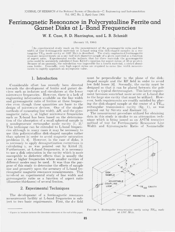
must b e perpendicular to t he pla ne o i' the di sks lHtped s;tmple and the RF field in order Lo al'oid low field losses [4]. Secondly, Lh e c,t l'iLy must be designed so LhaL it ca ll be placed b eL ween th e pol e caps of a t.vpi cal electrom agneL . Thi s lIttLer requireIll en t beco mes somewh ,tt more se l'ere at L-b;incl due to t he Lu ge s ize ca l'ity LhltL musL be u Lili zed . !TowOl"er , both requiremell Ls a re readily saLisfied by placin g Lhe disk-sha ped sltillple at Lhe center of ~t TE lo2 r ectangula r lransmiss ion CH I"i ly (fig. 1), as was poi n ted out by Sin'eLz a nd Zneimer r3].
Th e measurement procedure u Lilized for obL;), inin g daLa in Ih is study is silllihtr to a n lit ten uation techniqu e which is b'ei Il g' issued as f\,Jl ASTM Le n b)' live method of tesL for F crrill11tgnetic R eso n;tI1ce Line Width a nd Gyromagnetic 'R tLio of N onm etttllic
1 / ;/
/1 / I
v"
I I I I I I .!-: " I J~ I . ~r"'"
/ 1 I I 1 I •
TE I02 CAVITY
RF MAGNE TI C LI NES
FIG U RE 1. R eetangulw' transmission cavity using 'l.'E102 mode at 1107 Me/s.

Magnetic Materials designated ASTM C524-63T. Our setup varies from the ASTM method in that the input power to the cavity is held constant and measurements are made with a precision attenuator located in the IF detection circuit following the cavity . The frequency is adjusted to give cavity resonance for the empty cavity, and the variable precision IF attenuator is set to Ao to give a convenient output reference level, as indicated on the output detector. The sample is then inserted, the d-c magnetic field adjusted for maximum absorption in the sample, the frequency adjusted for cavity resonance, and the precision attenuator set to obtain the same output reference signal. The new attenuator reading is defined as AT) and the d-c field reading is defined as Hr. The attenuator reading corresponding to the half-power points on the ferrimagnetic resonance loss curve of the sample is calculated from the following formula [6]:
( A o- A , )
A H= Ao+ 20 log 2- 20 log 10-----ZO- +1 .
The attenuator is now set at the calculated Al/2
valuE'. The d-c magnetic field necessary to return the output p'Jwer to its previous level on one side of resonance is then read and recorded. The d-c field is then similarly adjusted and recorded br the other side of resonance. The difference betweE'n these two d-c field measurements is the line width, f>.H.
The effE'ctive g:yromagnetic ratio for the case of a sphere is determined from the formula
27rJr '}'=--
H r (1)
where ir is the microwave frequency required for cavity resonance at maximum sample absorption and Hr is the corresponding d-c field. In the case of a disk magnetized perpendicular to its plane, the gyromagnetic ratio is given by
(2)
which is Kittel's equation where the demagnetizing factors N x and Ny are equal and N x+ N y+ N z= 47r. M z is the magnetic moment per unit volume.
As can be seen in figure 1, the sample is oriented with its plane perpendicular to the E-field in the cavity. Even though it is at an electric field node, the diameter of the sample must be restricted in order to avoid errors due to dielectric effects. At higber frequen cies where smaller cavities may be used , it is possible to pick a cavity mode in which the plane of a disk may be parallel to the electric field in the cavity. In these cases, dielectric effects are avoided by baving a sufficiently thin sample located at an electric field node [7]. The necessity of placing the plane of the disk perpendicular to the E-fielcl in the L-band cavity is not a serious problem due to the longer wavelength involved. This was experimentally verified by comparmg Hr and line width
86
data on disks of }~ in. diam with corresponding data on the same disk reduced to ~~ in . diam and ground to the same aspect ratio . Resonant field measurements agreed within 0.3 percent for a given sample for three different materials. The dielectric effect on H ; may thus be considered negligible. For a fourth material, a distinct diameter dependence anomaly was observed, as will be described below. Since the dielectric constant of this material is comparable to that of the other three materials , it is believed that this anomaly is not due to dielectric effects. In the case of line widtb measurements, the variation between different diameter disks may be as great as 5 percent for all four materials. This small diameter dependence was not considered a serious error since the accuracy of the line width measurements due to sample variations, etc., was also of the order of 5 percent. Furthermore, it will be noted later that much larger errors in line width ma,y arise unless disks having large diameter to thickness ratios are used , It appears that a }~ in. disk offers a good compromise for keeping dielectric effects on line widths low while attaining high aspect ratios.
The samples were supported by a rexolite holder at the center of the cavity. The dielectric constant of the rexolite introduced negligible error in the measurement, as was determined from similar measurements using a polyfoam holder,
Possible errors due to wall effect were checked by measuring the disk at various distances from the broad wall of the cavity. The sample is normally placed at % of tbe distance between the broad walls. Placing the sample % and }~ of this distance from one of the walls resulted in only negligible change in the resonant measurements.
Many of the materials designed for use at the low microwave frequencies have relatively low Curie temperatures which may introduce errors in the data due to ambient temperature fluctuations. This situation is more serious in disk samples since the temperature dependent magnetization appears in the gyromagnetic ratio formula as given in eq (2). These effects were essen tially a voided by stabilizing the cavity temperature by means of coils carrying cons tan t temperature water ,
Having experimentally demonstrated that the above effects do not in troduce appreciable errors in the measurements , the maiority of the effort was directed towards a study of the dependence of f>.H
. (diameter) . and 'Y on the aspect ratIO thO k or the dIsks. . IC ness Early measurements indicated that more consistent data could be obtained from a given sample that was alternately ground down and measured rather than comparing data from several different samples of the same material. Initially, ultrasonic machining and diamond wheel grinding were used to cut a disk sample to a given Jiameter and thickness. A small rotary grinder using aluminum oxide oDtical finishing powder was then used to grind off small increments of thickness allowing many measurements on the same sample with a given diameter. In general there

appeared to be no dependence of the resonance properties on surface finish for three of the materials , as was determined by using powders of different grit size. However, in t he material no ted above which showed anomalous efl' ects for H T , a surface finish dependence was noted.
3. Results
The four commercially available materials referred to above and for which the line wid th , dH , and resonant field, H T , were determin ed as a function of the aspect ratio of the disks have the following general composition:
Sample A- Yttrium iron garnet Sample B- Magnesium, manganese, aluminum
ferrite Sample C- Substituted yt trium iron garnet Sample D- Nickel aluminum ferrite .
All measuremen ts were made at 1107 M c/s.
3.1. Gyromagnetic Ratio
Figure 2 shows EfT versus aspect ratio [or t he first three materials above. It can be seen that in at least two cases an asymptotic value of resonant field
13 20 ,--,------,--..,.----,---.-----,
2100 <!
1280 ..J
A " DISK DI AMETE R - .500" _ 2050 a: w I-
1240 " ::!'
2000 a: 0
u u.
0 1200 -z V)
<! 19 50 0 w
CD U60
l-V) 0::
(f) w ..J <! 1900 ~ a:
1120 w f-<!
'r." .501"
::!' 1850
a: 1080 0 u.
(f)
0 w 1040 f-(f) a: w ~ 1000
I~
960
920
880
120
ASPECT RATI O
FIGURE 2. Resonant field, H r , versus aspect ratio for disk samples of three materials, A, B, and C.
87
was not reached even for aspect ratios greater than 100, which in this case corresponds to disks less than 0.005 in. in thickness . This of course indicates that in such measurements i t is not, in general, reasonable to assume that one has an infinitely thin disk such that demagneti7.at ion corrections are not needed . H owever , these curves essentially express the dependence of Ki ttel 's r elation as given in (2) on demagnetizing factors which are a fun ction of the aspect ratio. The relationship between the demagnetizin g factors of ellipsoidal samples and their aspect ratios has been given by Stoner [8]. Thus (Nz- N x ) for a gi \'en disk may be readily obtained if we assume that t he demagnet izing factors of an ellipsoid and disk of the same aspect ratio are iden tical. The value of m agnetization, M ., may be determined from an independent measurement using a magnetometer. Thus , kn owin g lVIz and t he value of N z - N x as well as FIT as gi \Ten on t he curve for l1
given aspect ratio, one can calculate the gyromagnetic ratio from eq (2). This should be a constant, independen t of aspect ratio. When this was done for the data shown in figure 2, it was found that the yari ation in 'Y as a [unction of aspect ratio for ratios o[ 50 or hi gher was less than 1 percent for each of the three samples. This was co nsidered as satisfacto ry agreemen t between TGttel 's equation and the observed data.
The validi ty of the assump tion of equivalent demagnetizing factors for disks of t he same aspect ratio was further substantiated by grindin g ellipsoids from several disks keeping the aspect ratio approximately constant. A negligible effect on the measured value of I-IT was observed . This assumption thus appears to be valid at least for polycrystalline materials for measurements of this type. It has been noted in t he literature that this s ituation may not necessarily be true for other types of measurements such as tbe study of ma,gnetostatic modes ill single crystal disks [9].
The above discussion implies that Kittel's equat ion is quite applicable for predictin g the gyl'omagnetic ratio of most samples. However, similar measuremen ts taken on Material D, which is a nickel aluminum ferrite, showed an ano malous behavior as can be seen in figure 3. This material varies from the previous ones described in t hat EfT decreases for the higher aspect ratios and t he data is strongly diameter dependent . R ecent work indicates that HT is also dependent upon surface finish . The cause of this behavior is not yet und erstood. However, it is appar ent that Kittel's equation as given in (2) is no t applicable for describing this material. It th us appears t hat care should be taken in applying Kittel's equation to an unknown sample without flrst determining that t lte material is not [ollowi.ng an unusual behavior. This implies that it may be necessary to m easure samples of several different aspect ratios when gyromagnetic ratio data is desired .

1000
980
960
DISK DIAMETER - .498" 940
920
Cf) 900 0 W I- DISK DIAMETER - .250" Cf)
a: w 880 Q
r 860
840
820
800
780
120
ASPECT RATIO
FIGURE 3. Resonant field, H" versus aspect ratio f or disk sample of material D.
3.2 . Line Width
Figure 4 shows the line width of materials A through D as a function of the aspect ratio of the disk-shaped samples. Here again, it is seen that it is difficult to obtain disks sufficiently thin in order to obtain an asymptotic value of line width. It may thus be necessary to obtain data at several different values of aspect ratio and extrapolate the results to the higher aspect ratios in order to obtain meaningful information on line width. It is readily apparent that samples B , C, and D are displaying similar phenomena in that they show a relatively slow decrease in line width as the aspect ratio increases. This decrease in line width with increflosing aspect ratio is probably due to inhomogeneous field effects as well as incomplete saturation of the individual crystallites. The inhomogeneous field effect might be expected to result in magnetostatic modes arising from field inhomogeneities due to spacial variations in the demagnetizing field resulting £rom deviation of the disks from true ellipsoids such as described by Geschwind and Clogston [10]. The problem of incomplete saturation might be expected
88
220
200 D
180 DISK DIAMETER - .498"
160
Cf)
0 140 w I-Cf)
0:: w 0 120 r I-0
~ 100 w 2 :;
eo
60
XI A {o DIAMETER - 500" , ( X DIAMETER - 370"
\ oJ"'K"l>"X....o,o 0 ~,-
40
DISK DIAMETER - .488"
20
00 120
ASPECT RATIO
FIG U R E 4. Line width versus aspect ratio for disk samples of materials A, B, C, and D.
to cause a lin e broadening if the relatively low internal d-c fields in the disk required for resonance at L-band become of the same order of magnitude as the anisotropy fields such floS discussed by Suhl et al. [11] . The greatest variation in line width with aspect ratio in the data given in figure 4 floppears on the low field side of the resonance curves. This effect might be expected for both lin e broadening mechan isms described above. As such, it does not appear possible at the present time to separate the eftects due to saturation from the various possible inhomogeneous field effects that may be present in this data. One further point of interest in regard to this data is that sample D does not display an anomalo us behavior in line width even though there was a strong dependence of resonant field on diameter and surface finish.
Sample A, which is yttrium iron garnet, shows a somewhat different dependence of line width with aspect ratio . For this case, the line width appears to be relatively constan t for the higher aspect ratios. As can be seen, it is possible that there is actually a slight increase in line width as the aspect ratio

increas es in this rnaterial. This apparen t increase in lin e width for the higher aspect ratios is not en tirely unders tood althougll here again , the increase is largely due to chan ges in the low field sid e of th e resonance curve. It is also of in teresL to note that t he resonance curves [or this materi al were in general more sym metrieal t han for Lhe previous materials B, C, and D . This is ill agreement with d~1ta obtained on sin gle crys tal dis],s of YJ G by Smith and Watann,be [1 2]. Th e ~6 i.n. diam sH,mples o[ this material proved to be Loo lossy Jor measurements at the lower aspect ratios. However , data taken 011 a smaller % in. diam sample of yttrium iron garn et indicated that there is a very large increase in lin e width at aspect ratios of the order of ten or less. This is presumably due to the fact th at these samples are becoming magnetically unsaturated at the lower «spect ratios . Tt should also be noted that varitLtion s in dattL on different samples of t he sam e diam eter cut from the same block were noted for this material. Thi s apparent inh omogeneity ill such mH teri tds consid entbly effects the pr ecision of me<1s urements such as descr ibed above w hen differ ent samples must be used.
A fina l renhlrk con ccrnin g Lhe comparison of line width measurement s b etween ellipsoids and disks of the same aspect ratio for t he above four materi als may be oJ in terest. It has previously been men tion ed t hat a neglig ible varia,tion in r esonant field was noted when n, disk WftS ground to ftl1 ellipsoid of the Sfl.m e aspec t ratio . However , for the case of samples B , C , and D , Lhe ellipsoid IHLd a smftller line width than the disk of th e StLlll e aspect ratio . For sample A, th e ellipsoid had a greater lin e width t itan til e correspondin g disk . This s uggests that magnetostatic Illode ph enomena n,{J'ec ts t he line wid til bu t no t the resonant field in these po]ycr ys tallin e III ft tel' ials.
4. Conclusions
1. The use of a TI~I 02 rec tangular cavity is qu ite applicable for measurin g the effective lin e width and gYI"omagnetie ratio of dislt-shaped samples at L-band frequen cies.
2. In many cases , it may be necessary to obtain line width and gyromagnetic ratio as a function of aspect ratio and ex trajJolate the data to obtain the asymptotic values for these quantiti es. However ,
for many materials, the gYI'omagnetic ratio of a finite disk may be calculated from Kittel's eq uation jf one uses t he appropriate demagnetizing factors a,nd has a va.lue of M available.
0. In at least on e Cttse such as nickel aluminum ferrite, it is not possible to fit Kittel's equation in its usual form to th e c urves givin g resonant field as a function of aspect ra.tio. Su ch an anomaly appears to be associated wi th both a diameter and surface fm ish depend en ce of Hr as a fun ction of t he aspect mtio. Consid erable care should thus b e given to th e in terpretation or data of this type on such materi/Lls a t L-b/wd frequ encies.
5. References
[ I] Ar tm a n, J. 0. , and P. E . Tann(' n"'ald , lVlrasu]"(: ment of susceptib ili ty jrnso r in ferri tes, J. Appl. Ph ys. 26, K o. 9, 11 2·1- 11 :32 (19 55) .
[2] Sooh oo, n. F. , Th C'o ry and a pplicat io n of f( ' rri tC's, p p. 92- 99 ( Prent ice-Ha ll , In e., Eng\('\\'ood C li ffs, N r w J C' rs('y, 1960) .
[:3] f-i il ·\'('tZ, i\LH. , and J. l~ . Zll('im r r, :'I li crolVa \"(' pro pC'r t ies of polyc rystalli nc l"al'e (' a r t h ga rn ets , J . Appl. Ph ys. 29, ·1·31 (19:")8).
[41 Lax, B. , and K. J. Butto n, :'I l icro \\"a \'C' f(' r rilPs an d fr ]"]"i mag net ics, pp. -18 ·1-·185 (:'Il c(;ra \\'-Hill Co mpany, In c., N ('\\' York, N. Y. , J 962) .
89
[.5] J\:itte l, C. , On t hC' t heo ry of ferro magn(,t ic reso nance a i-sorpt io n, I' hys. R r v. 73, 155- 161 ( 1!J48) .
[6] PI'('s to n, C. C., a nd W. R, CasC', T ab les t o fa c ili tate t he d('t('rm ina tio n of t he' ferr imagnct ic r esona nce lin e " ' idth o f non- l1wtaJli c mag net ic ma t r ri a ls, N B~ T ech. ?\ote :\0. In (Apr . 19 6:3) .
[7] Von Auloc k, W ., a nd ,J . H . RO\\'en, :'I[easure ll1c nt of di d ectri c and magnC't ic propr rt ips of ferromagnet ic malP ria ls at mi crowan' fr(,qu encies, Bell Sys tem T ech. J. XXXVI, No . 2, ,127 ( I !).I7) .
[8] StonC' r, I ~ . C., The d('m ag n('t izing facto rs for r llipsoids, Ph il. M ag. (7) 36, 80:3- 82 1 (19·1.5) .
[H] i)illo n, J. P., ::'I l ag nC'tostat ic mod rs in dis ks an d rods , .J . Appl. Ph ys . 31, :\0.9, J 60:")- 1 614 (Sep t. 1960) .
[10] ( :('schwind , S., a nd A. :'If. Clogsto n, Na rrowin g (' ff C' ct of dipolr fo rces on inholl1og('nC'ously broackll C'd li m's, Ph ys. R c\, . 108, No . ] , 4H- 53 (Oct. ] 957) .
[J I] 8 uhl , H ., L . O . Va n U it r rt , and J . L. DaviS, FelTomagIl (,t ic rcso nan cr in mag n('s ium- ma nga m's(' a luminum fC' rri tc betw('en 160 a nd .1 900 :'l Ie , J . Appl. Ph ys. 26, X o. 9, 11 80 (f-ip p t . 105,5) .
[12] S mi t h, A . \V., a nd A. W ata nabe, Ff'rrim agnet ic ]'('so ll allce in a s in gle-c r.vsta l disk of yttriu m iron ga rn et , J. Appl. Ph ys., Rupp lC' nw n t to Voluln e 32, No. :3 , 1558 (1961) .
(Paper 68C2- 154)