effects of parallel programming design patterns …etd.lib.metu.edu.tr/upload/12612101/index.pdf ·...
TRANSCRIPT

EFFECTS OF PARALLEL PROGRAMMING DESIGN PATTERNS
ON THE PERFORMANCE OF MULTI-CORE PROCESSOR
BASED REAL TIME EMBEDDED SYSTEMS
A THESIS SUBMITTED TO
THE GRADUATE SCHOOL OF NATURAL AND APPLIED
SCIENCES
OF
MIDDLE EAST TECHNICAL UNIVERSITY
BY
BURAK KEKEÇ
IN PARTIAL FULFILLMENT OF THE REQUIREMENTS
FOR
THE DEGREE OF MASTER OF SCIENCE
IN
ELECTRICAL AND ELECTRONICS ENGINEERING
JUNE 2010

Approval of the thesis:
EFFECTS OF PARALLEL PROGRAMMING DESIGN PATTERNS ON THE PERFORMANCE OF MULTI-CORE
PROCESSOR BASED REAL TIME EMBEDDED SYSTEMS
submitted by Burak KEKEÇ in partial fulfillment of the requirements for the degree of Master of Science in Electrical and Electronics Engineering Department, Middle East Technical University by,
Prof. Dr. Canan ÖZGEN ________________________ Dean, Graduate School of Natural and Applied Sciences Prof. Dr. İsmet ERKMEN ________________________ Head of Department, Electrical and Electronics Engineering Prof. Dr. Semih BİLGEN ________________________ Supervisor, Electrical and Electronics Engineering Dept., METU Examining Committee Members: Prof. Dr. Hasan GÜRAN _______________________ Electrical and Electronics Engineering Dept., METU Prof. Dr. Semih BİLGEN _______________________ Electrical and Electronics Engineering Dept., METU Assoc. Prof. Dr. Cüneyt BAZLAMAÇCI _______________________ Electrical and Electronics Engineering Dept., METU Asst. Prof. Dr. Şenan Ece SCHMIDT _______________________ Electrical and Electronics Engineering Dept., METU Şafak ŞEKER _______________________ Lead Design Engineer, ASELSAN INC.
Date: _______30.06.2010_______

iii
I hereby declare that all information in this document has been obtained
and presented in accordance with academic rules and ethical conduct. I
also declare that, as required by these rules and conduct, I have fully
cited and referenced all material and results that are not original to this
work.
Name, Last name : Burak KEKEÇ
Signature :
iv
ABSTRACT
EFFECTS OF PARALLEL PROGRAMMING DESIGN PATTERNS ON THE
PERFORMANCE OF MULTI-CORE PROCESSOR BASED REAL TIME
EMBEDDED SYSTEMS
KEKEÇ, Burak
M.Sc., Department of Electrical and Electronics Engineering
Supervisor: Prof. Dr. Semih BİLGEN
June 2010, 114 pages
Increasing usage of multi-core processors has led to their use in real time
embedded systems (RTES). This entails high performance requirements
which may not be easily met when software development follows traditional
techniques long used for single processor systems. In this study, parallel
programming design patterns especially developed and reported in the
literature will be used to improve RTES implementations on multi-core
systems. Specific performance parameters will be selected for assessment,
and performance of traditionally developed software will be compared with
that of software developed using parallel programming patterns.
Key Words: Multicore programming, real-time embedded systems, design
patterns

v
ÖZ
PARALEL PROGRAMLAMA TASARIM ÖRÜNTÜLERİNİN ÇOK İŞLEMCİLİ
GERÇEK ZAMANLI GÖMÜLÜ SİSTEM PERFORMANSI ÜZERİNDEKİ
ETKİSİ
KEKEÇ, Burak
Yüksek Lisans, Elektrik ve Elektronik Mühendisliği Bölümü
Tez Yöneticisi: Prof. Dr. Semih BİLGEN
Haziran 2010, 114 sayfa
Çok çekirdekli işlemcilerin yaygınlaşması, bunların gerçek zamanlı gömülü
sistemlerde (GZGS) de kullanılmasına yol açmıştır. Ancak bunun gerektirdiği
yüksek performans, tek işlemcili sistemler için kullanılan geleneksel
yöntemlerle geliştirilmiş yazılımlarla sağlanamayabilmektedir. Bu çalışmada,
GZGS performansı ölçütleri seçilecek ve özel olarak bu amaca yönelik olarak
tanımlanmış ve literatürde tartışılmış bulunan paralel programlama tasarım
örüntüleri kullanılarak elde edilen performans ile geleneksel yöntemlerle
geliştirilen yazılımların performansı karşılaştırılacaktır.
Anahtar Kelimeler: Çok çekirdekli işlemci programlama, gerçek zamanlı
gömülü sistemler, tasarım örüntüleri

vi
To Melik Gazi…

vii
ACKNOWLEDGMENTS
I would like to thank Prof. Dr. Semih BİLGEN for his valuable supervision,
support and guidance throughout the thesis work.
I am grateful to Şafak ŞEKER and my other colleagues for their supports
throughout the thesis work. I am also grateful to Aselsan Electronics
Industries Inc. for encouragements and resources that are supported for this
thesis.
I would like to thank to TUBİTAK for scholarship throughout this study.
Finally, I owe my deepest gratitude to my parents and my brothers for their
encouragements and to my dear who is my everything.

viii
TABLE OF CONTENTS
ABSTRACT .................................................................................................... iv
ÖZ ................................................................................................................... v
ACKNOWLEDGMENTS ............................................................................... vii
TABLE OF CONTENTS ............................................................................... viii
LIST OF ABBREVIATIONS ........................................................................... xi
LIST OF TABLES .......................................................................................... xii
LIST OF FIGURES ...................................................................................... xiii
INTRODUCTION ........................................................................................... 1
BACKGROUND ............................................................................................. 4
2.1 Multicore Processors ........................................................................ 4
2.2 Parallel Computing and Symmetric Multiprocessing (SMP) .............. 5
2.3 Multicore Programming Challenges and Approaches ....................... 6
2.4 Patterns for Parallel Programming Design Approach ..................... 10
2.4.1 Design Patterns & Pattern Language: ...................................... 10
2.4.2 Design Patterns in Real-Time Systems: ................................... 11
2.4.3 Parallel Programming Patterns................................................. 11
2.4.3.1 Parallel Programming Pattern Language ........................... 12
2.4.3.2 Our Pattern Language (OPL) ............................................. 18
2.5 Real Time Performance Metrics ..................................................... 20
IMPLEMENTATION ..................................................................................... 24
3.1 VxWorks OS & VxWorks 6.6 with SMP........................................... 24
3.2 Wind River WorkBench 3.0 ............................................................. 28
3.2.1 VxWorks Image Project: ........................................................... 30
3.2.2 VxWorks Downloadable Kernel Module Project: ...................... 30
3.2.3 Debugger ................................................................................. 31
3.2.4 Additional Tools ........................................................................ 31
3.2.4.1 System Viewer ................................................................... 31
3.2.4.2 VxWorks Simulator ............................................................ 32
3.2.4.3 Function Tracer .................................................................. 33
3.3 Experiment Setup ........................................................................... 34
3.3.1 Host Machine ........................................................................... 34

ix
3.3.2 Target Machine ........................................................................ 36
3.3.2.1 Wind River SBC8641D: ..................................................... 37
3.3.2.2 Freescale MPC8641D ....................................................... 37
3.4 Test Project ..................................................................................... 38
3.4.1 List Management Software: ...................................................... 38
3.4.2 Design of Parallel Test Software: ............................................. 45
3.4.2.1 Finding Concurrency Phase............................................... 45
3.4.2.2 Algorithm Structure Phase ................................................. 55
3.4.2.3 Supporting Structure Phase ............................................... 58
3.4.2.4 Implementation Mechanism Phase .................................... 60
EVALUATION .............................................................................................. 73
4.1 Test Method: ................................................................................... 73
4.1.1 “Define”s in Software: ............................................................... 74
4.1.2 Auxiliary Testing Program: ....................................................... 75
4.2 Input Set: ........................................................................................ 77
4.3 Test Cases: ..................................................................................... 78
4.3.1 Test Case 1: Timeline Measurement Test ................................ 78
Goal of test: ....................................................................................... 78
Testing Method: ................................................................................ 78
Evaluation Method: ........................................................................... 78
Expectations: ..................................................................................... 79
Result: ............................................................................................... 81
4.3.2 Test Case 2: Consistency Test ................................................ 85
Goal of test: ....................................................................................... 85
Testing Method: ................................................................................ 85
Evaluation Method: ........................................................................... 86
Expectations: ..................................................................................... 86
Result: ............................................................................................... 86
4.3.3 Test Case 3: Computation Time Test ....................................... 86
Goal of test: ....................................................................................... 86
Testing Method: ................................................................................ 87
Evaluation Method: ........................................................................... 87
Expectations: ..................................................................................... 87
Result: ............................................................................................... 88
4.3.4 Test Case 4: Time Constraint Test ......................................... 103
Goal of test: ..................................................................................... 103
Testing Method: .............................................................................. 103

x
Evaluation Method: ......................................................................... 104
Expectations: ................................................................................... 104
Result: ............................................................................................. 104
DISCUSSION AND CONCLUSION ........................................................... 106
REFERENCES .......................................................................................... 109
APPENDIX-A ............................................................................................. 113

xi
LIST OF ABBREVIATIONS
OS: Operating System
SMP: Symmetric Multiprocessing
SISD: Single instruction single data
SIMD: Single instruction multiple data
MISD: Multiple instruction single data
MIMD: Multiple instruction multiple data
RT: Real-Time
UE: Unit of execution
PE: Processing Element

xii
LIST OF TABLES
Table 2.1: Relationship between Supporting Structures patterns and
Algorithm Structure patterns [1] ............................................................................ 15
Table 2.2: Relationship between Supporting Structures patterns and
programming environments [1] ............................................................................. 16
Table 4.1: Computation time change in usec for the same input .................. 104
Table A.1: Test Input Set ..................................................................................... 113
xiii
LIST OF FIGURES
Figure 3.1: VxWorks Tasks .................................................................................... 25
Figure 3.2: User Interface of Wind River Workbench ........................................ 29
Figure 3.3: Experiment Setup ................................................................................ 34
Figure 3.4 Flow Chart of the List Management Algorithm ................................ 39
Figure 3.5: Flow Chart of Update Decision Algorithm ....................................... 42
Figure 3.6: Flow Chart of Updating algorithm ..................................................... 44
Figure 3.7: Task group ordering for Design Approach 1 ................................... 50
Figure 3.8: Class Diagram Of List Management Problem ................................ 63
Figure 3.9: Message Sequence Diagram of the List Management Software 64
Figure 4.1 Auxiliary testing Program .................................................................... 76
Figure 4.2: Timing for 3rd input arrival for Serial Design.................................... 81
Figure 4.3: Timing for 3rd input arrival for Parallel Design 1 ............................ 82
Figure 4.4: Timing for 3rd input arrival for Parallel Design 2 ............................ 83
Figure 4.5: Timing for 3rd input arrival for Parallel Design 3 ............................ 84
Figure 4.6: Arrival - computation time graph for 1 to 250 elements of input
file for all design when there is no kill time .......................................................... 89
Figure 4.7: Arrival - computation time graph for 1 to 100 elements of input file
for all design when there is no kill time ................................................................ 90
Figure 4.8: Arrival - computation time graph for 1 to 250 elements of input file
for all design except Design 1 when there is no kill time .................................. 92
Figure 4.9: Arrival - computation time graph for 1 to 100 elements of input file
for all design except Design 1 when there is no kill time .................................. 93
Figure 4.10: Arrival - computation time graph for 1 to 250 elements of input
file when killtime is set to 10 usec. ....................................................................... 95
Figure 4.11: Arrival - computation time graph for 1 to 50 elements of input file
when killtime is set to 10 usec. .............................................................................. 96
Figure 4.12: Arrival - computation time graph for 1 to 250 elements of input
file when killtime is set to 10 usec. ....................................................................... 98
Figure 4.13: Arrival - computation time graph for 1 to 50 elements of input file
when killtime is set to 10 usec. .............................................................................. 99
Figure 4.14: Arrival - computation time graph for 1 to 250 elements of input

xiv
file when killtime is set to 100 usec. ................................................................... 101
Figure 4.15: Arrival - computation time graph for 1 to 50 elements of input file
when killtime is set to 100 usec. ......................................................................... 102
1
CHAPTER 1
INTRODUCTION
Development in science and the technology has triggered many
improvements in the computation area. The problems to be solved by
computers become bigger and more complex. This requires faster
computers. To meet this requirement multicore processors have been
introduced. Multicore processors are composed of two or more independent
processing elements with fast interface between the processing elements.
While multicore processors are new in computing technology, actually,
parallel computing and multithreading concepts are not new. However with
multicore processors these concepts have become more important.
To obtain better performance from multicore processors, software developers
must respond to multicore processors solutions of chip developers by
developing proper software with parallel programming effort. However to
perform this, software developers face lots of challenges such as parallelizing
tasks, data synchronization, load balancing, avoiding race conditions etc.
Parallel programming design patterns or pattern languages are helpful
solutions to overcome these challenges.
The aim of this thesis study is to evaluate the effectiveness of a specific
parallel programming design pattern language proposed by Mattson et.al. [1],
2
via a case study that involves a real time list management algorithm
implementation.
In the scope of the present study, the list management algorithm which has
been implemented as serial by traditional coding style, is re-implemented
using the parallel programming design pattern language in [1] to exploit the
concurrency provided by the multicore processors. Parallel implementation is
made using three different design approaches which include different
patterns from that pattern language.
After implementations of the serial and three different parallel designs, each
parallel implementation will be compared with the serial implementation and
other parallel implementations with respect to the real time performance
metrics. Then this comparison results will be evaluated and some inferences
are derived about parallel programming.
The remaining chapters of the thesis are organized as follows:
In Chapter 2 background information about multicore processors, parallel
computing and symmetric multiprocessing, multicore programming and its
challenges, pattern, pattern language concepts and parallel programming
patterns is presented. Moreover information about real rime software and real
time performance metrics are also introduced.
In Chapter 3 experimental work in the thesis is explained. The software
development environment, hardware components and connections between
them in the experiment setup, and the software and tools are introduced.
Also the list management algorithm that is implemented in the thesis,
implementation details of serial and three parallel software design tested,
parallel programming patterns and their usage in the software are also
presented.
3
In Chapter 4 test method to compare the one serial and three parallel
implementations with respect to the real time performance metrics is
explained. Different test cases to evaluate the software with respect to the
different real time performance metrics are explained in details. Moreover,
some graphs and tables are formed with the output data obtained from the
described test cases.
In Chapter 5 the one serial and three parallel different implementations of the
list management algorithm are summarized and compared with respect to the
real time performance metrics. Also suitability of the selected patterns for the
parallel designed software is discussed and some inferences about the
pattern selection for the different versions of the algorithm are stated. After a
review of achievements and shortcomings of the study, suggestions for future
work are also presented in this concluding chapter.
4
CHAPTER 2
BACKGROUND
2.1 Multicore Processors
Traditional methods to increase performance of a processor were using more
transistors on chips and increasing clock rate. However, this solution has
reached its limit. Since they cause high heat dissipation and too much power
consumption, chip developers have changed their methods. The new trend is
building chips with multiple cores instead of single core. This new method is
more power efficient and supplies better performance. [2] Thus, nowadays
multicore processors are preferred instead of single core processors.
Actually, multicore processor technology is an important solution for many
computing problems because some present problems and possible future
problems in human life require better performance. Multicore processors will
be indispensable for all areas of computing that require high performance
such as management of big databases, high quality PC animations and
games, high quality digital media, internet, data security etc. [3] As a result
usage of multicore processors has been increasing gradually with time.

5
2.2 Parallel Computing and Symmetric Multiprocessing
(SMP)
Sometimes single processor can not be practicable to solve some problems
that require high performance. Using more than one processor to work
concurrently is the solution for these problems. Processors can be connected
together in different ways. There are different kinds of parallel computing
architectures. These architectures can be roughly classified with Flynn’s
taxonomy which classifies parallel computing architectures with regard to
memory and instruction coherency. There are four types of structure in
Flynn’s taxonomy: SISD, SIMD, MISD, MIMD. [4] In SISD systems single
instructions access the single data and no parallelism can be exploited, in
SIMD systems single instruction access different data simultaneously, in
MISD systems multiple instructions process on the same data and in MIMD
systems multiple instructions process on different data. [5]
In parallel computing architectures processing elements can be on the same
machine or on distributed machines. If processing elements are on the same
machine, this kind of computing is named as multiprocessing. Multicore
processors are a kind of multiprocessing architecture with a difference that
parallelism is achieved not by processors but by processor cores. For
multicore processors, more than one core exists in a single processor. That
is, multicore processors are chip-level multiprocessing systems.
Symmetric Multiprocessing (SMP) is one of various parallel processing
approaches in which more than one identical processor can access a single
shared memory via a common bus. An identical copy of an operating system
runs on each processor. Also each processor has its own caches. Since
processors have identical architecture and instruction sets, a process or
thread can run on any of them. Thus workload can be balanced.
6
SMP approach can be used for multicore processors. SMP Multicore
processors can run a single OS which supports SMP such as VxWorks 6.6
SMP [6], Linux 2.6 [7] These OS can fulfill load balancing which is fairly
sharing out the overall processing workload to the processing elements.
2.3 Multicore Programming Challenges and Approaches
Before release of multicore processors, most software developers did not
have to consider parallelism, so serial programming was efficient. However
after beginning to use multicore processors, software developers must also
improve their code writing skills and they also rewrite their code that was
written for single core processors to reap the benefits of multi processors.
They must parallelize their codes, divide serial program into tasks that can be
run parallel on different cores simultaneously.
However this kind of programming is not easy. There are lots of challenges in
multicore programming. Sometimes difficulty arises from the problem
characteristic. Some problems can not be parallelized. Management of data
used for solving a problem is another major challenge. Sharing data between
tasks running in parallel and synchronizing the shared data are also
significant issues for parallel programming. Software developers must avoid
deadlocks and race conditions. [8] Partitioning of software into threads is
another important issue that developers must be careful. It must be adequate
for efficiency i.e. not too much and not too little. Also handling communication
mechanism between these threads is another challenge. Proper load
balancing must be ensured for avoiding mistakes due to disordered
execution of available threads in software. Beside multicore software design,
debugging is also a challenge for developers. [9]
Multiprocessing and multithreading are not new issues in programming but

7
with usage of multicore processors, they have become more popular.
Presently there are some software development tools (compilers, frameworks
etc.) that ease multithreading. [10] Nowadays companies continue to improve
their tools to overcome multicore programming challenges. [9] Some static
analysis tools have been developed to identify deadlocks and race
conditions. Also there are compilers and operating systems that support
development of multithreaded software. Moreover debugging tools have
been improved to perform multicore debugging. Also some Parallel
programming frameworks are available that ease the parallel programming.
However to be able to use these tools and to overcome multicore
programming challenges software developers must also improve their writing
skills and also change their viewpoint about problem analysis. Parallel
thought is a fundamental starting point of parallel programming. [11]
To overcome these challenges and to make parallel programming easier,
there are lots of studies. In the scope of these studies new parallel
programming languages, frameworks, design patterns, parallel software
architectures, libraries, run time environments are being introduced gradually.
There are some research groups that study on this area.
Parallel Computing Laboratory (Par Lab) at the University of California,
Berkeley is one of research group that study on parallel programming.
According to [12] Par Lab has a top-down from the application approach
instead of traditional bottom-up from the hardware approach. In parallel
program development approach of Par Lab, there are two layers. First one is
efficiency layer that includes optimized libraries and parallel programming
frameworks developed by the parallel programmer experts. Second one is
the productivity layer that includes composition and coordination language
which are used to develop applications by the help of the efficiency layer.
Application programmers or domain experts use the productivity of this layer.

8
Finally, autotuners which map the software efficiently to a particular parallel
computer are involved in Par Lab approach. [12]
Pervasive Parallelism Laboratory (PPL) at Stanford University is another
research group that study on parallel programming. PPL aims to make
parallel programming easier. PPL studies on specific applications in different
areas, programming models, software systems such as virtual machines,
optimized compilers etc. and hardware architectures. The key concepts of
PPL approach are domain specific languages, combining implicit or dynamic
and explicit or static management of parallelism in a common parallel
runtime, flexible hardware features. [13]
The Universal Parallel Computing Research Center (UPCRC) at the
University of Illinois is another research group that study on parallel
programming. UPCRC aims to develop a disciplined parallel programming
model that supported by sophisticated development and execution
environments as existing models in sequential programming. Also UPCRC
study on parallelism of all levels from application to hardware such as parallel
languages, autotuners, domain-specific environments, adaptive runtime
environments, hardware mechanisms, refactoring tools. Moreover UPCRC
aims to make future applications human centric. [14]
In [15], parallel computing approaches in ubiquitous programming of three
different groups involved three universities are maintained. The first group is
Parallel Computing Laboratory (Par Lab) at the University of California,
Berkeley. Par Lab team has defined their pattern language which includes
architectural and software patterns. Also they have formed a pattern-oriented
software framework to build the software architecture of the parallel program.
The second group is The Universal Parallel Computing Research Center at
the University of Illinois. They focus on programming language, compiler, and
runtime technologies supporting parallel programming. The third group

9
Stanford University’s Pervasive Parallelism Laboratory (PPL). Their goal is to
make parallelism accessible to average software developers. To do they
develop parallel domain-specific languages. Moreover all three groups study
on some other areas different from ubiquitous programming to develop
parallel programs.
In [16] a pattern language for distributed computing is introduced. Although
patterns involved in this pattern language are about distributed computing,
some of them can be used for parallel programming such as patterns about
concurrency, synchronization, message passing, data access.
In [17] Berkeley Par Lab’s approach to the parallel programming and their
studies are explained. Their studies are focused on both hardware and
software parts of the computation. They have developed application-driven
projects in different area by the helps of the domain experts. Par Lab
introduces a pattern language, frameworks, productive environments to
provide the abstraction of low level operations from the programmer. At the
last part of [17] four other projects related with the parallel programming
challenge are mentioned. One of them is The Universal Parallel Computing
Research Center of the University of Illinois. They focus on productivity in
specific domains than on generality or performance. They are advancing
compiler to determine potential parallel parts. Also they develop frameworks
that generate domain specific environment that provide an abstraction of
parallel programming details. Another project is belongs to The Pervasive
Parallelism Laboratory at Stanford University. Their approach includes
domain specific languages and a common parallel runtime environment.
Georgia Tech University is another group which develops different
applications for Cell Broadband Engine Processor. Another project is The
Habanero Multicore Software Project at Rice University. Languages,
compilers, libraries, and tools are being developed in this project.

10
In [18] a new language for multicore processors, Manticore, is introduced.
This language is a general-purpose programming language i.e. it is not
developed for a specific field and it is also a parallel programming language.
Parallel programming patterns or pattern languages can be a common
solution to parallel programming challenges for different domains. Two
parallel programming pattern languages are reviewed in further detail in the
next chapter.
2.4 Patterns for Parallel Programming Design Approach
2.4.1 Design Patterns & Pattern Language:
The concept of design patterns was first introduced by architect C. Alexander
and some design patterns were offered to some common problems in area of
architecture. In course of time this concept was entrenched in the area of
software development. [19]
Software design patterns are generalized, time-tested and high-quality
solutions to recurring problems that software developers frequently face with.
These solutions are recorded within a predefined context which generally
contains the name of pattern, problem, forces, solution etc. Thanks to this
well-defined context, readers can understand design patterns quickly. Design
patterns are also good method for sharing experience between experts of an
area. Furthermore, design patterns generate a common vocabulary between
people working in the same area. This provides better communication in the
domain. [1]
Pattern languages are structured collection of patterns, or “the web of
patterns”. Pattern languages help developers to select appropriate patterns in
complex designs.

11
There is a strong relation between some patterns in other words; actually
some patterns complete each other. Thus, in design process, each selected
pattern in pattern language leads to some other patterns. [1][20]
2.4.2 Design Patterns in Real-Time Systems:
Although design patterns concept has been used in software for years, their
usage in Real-Time (RT) software has not been soon. Some reasons for this
delay stem from the nature of RT software. Mostly RT software must run on a
particular hardware and this hardware has some limitations on memory, size,
power etc. Since software patterns consume some of these limited hardware
features, RT software developers could adapt to design patterns after
improvements in hardware technologies.
Another reason for the delay in design pattern usage in RT software is that
generally RT software developers are domain experts but not software
development experts. Thus, enhancement of their software developing skills
took some time. [21]
After usage of design patterns in RT software, some additional patterns that
offer solutions to problems concerning RT software specifically have been
developed.
2.4.3 Parallel Programming Patterns
After parallel computing became popular, software developers started to
develop new skills to exploit concurrency. Then, some software design
patterns and pattern languages have been developed for parallel

12
programming software to overcome some common problems and also to
form better parallel software architecture. The first parallel programming
pattern language was introduced in [1] by experts of parallel computing.
Another pattern language for parallel programming is currently being
developed by Berkeley Par Lab. [20]
2.4.3.1 Parallel Programming Pattern Language
In [1], Mattson, Sanders and Massingill collect and combine the experiences
of experts in the parallel programming field. They present this collection as a
pattern language which is a familiar method for software developers.
This pattern language is composed of four phases of parallel programming.
Visiting these four phases sequentially with a top-down approach is
recommended to parallel software developers. From top to down these
phases are Finding Concurrencies, Algorithm Structure, Supporting
Structures and Implementation Mechanisms.
2.4.3.1.1 Finding Concurrency Design Space:
In this design space of pattern language, the problem that is tried to solve
with a parallel program is analyzed by the developer. This analysis is focused
on problem size, possible tasks that solve the problem and data that would
be used by tasks. After this analysis, the developer decides whether the
parallel program effort is worthwhile or not for this problem. Also the
developer determines the tasks, data and possible concurrent parts in the
program.
The patterns in this design space can be divided into three groups.

13
Decomposition Patterns:
There are two patterns under this group which are Task Decomposition
Pattern and Data Decomposition Pattern. By the help of these patterns the
problem is decomposed into tasks that can be executed concurrently and
data used by the tasks. Actually there is a strong interaction between these
two patterns but according to the problem, one of them is selected for start.
Dependency Analysis Patterns:
Group Tasks Pattern, Order Tasks Pattern, and Data Sharing Pattern are
included in this group. Thanks to these patterns dependencies between tasks
are defined.
Design Evaluation Patterns:
Owing to this pattern the software developer can evaluate the design made in
this design space. After the evaluation software developer decides whether
to continue with this design or turn back and correct the design.
2.4.3.1.2 Algorithm Structure Design Space
In this design space, the software developer tries to distribute the
concurrency found in the first phase to the unit of executions (UEs), namely
threads or processes, by using patterns involved in this design space.
Most appropriate pattern or patterns must be selected for the problem. While
making this selection, the developer must consider some software forces
such as Efficiency, Simplicity, Portability and Scalability and also features of
the target platform on which the parallel program run. Sometimes these
factors can lead to conflicts. Thus the developer must optimize the selection.
Appropriate pattern selection depends on the specific problem. The potential

14
concurrent part of the problem is the major factor for this selection. This
factor is named as major organizing principle. According to the problem, a
task group, data or flow of data may be the major organizing principle.
Eventually the developer determines to the major organizing principle, the
most appropriate pattern or patterns for design is selected. The developer
must also consider the software quality factors and sometimes the hardware
on which the program will run.
Organize By Tasks:
If execution of tasks is the major organizing principle, patterns in this group
can be selected. Task Parallelism Pattern and Divide and Conquer
Pattern are patterns in this group. Selection of one of these patterns is made
according to the enumeration of the tasks. If tasks are enumerated linearly
then Task Parallelism Pattern is selected else if they are enumerated
recursively then Divide and Conquer Pattern can be selected.
Organize By Data Decomposition:
If decomposition of the data is the major organizing principle patterns in this
group can be selected. Geometric Decomposition Pattern and Recursive
Data Pattern are patterns in this group. Selection of one of these patterns is
made according to the structure of data decomposition of the problem. If data
is decomposed linearly then Geometric Decomposition Pattern is selected
else if data has a recursive data structure then Recursive Data Pattern can
be selected.
Organize By Flow of Data:
If flow of the data is major organizing principle patterns in this group can be
selected. Pipeline Pattern and Event-Based Coordination Pattern are
patterns in this group. Selection of one of these patterns is made according
to the data flow order. If data flow regular and static then Pipeline Pattern
15
can be selected else if it is irregular and/or dynamic then Event-Based
Coordination Pattern can be selected.
2.4.3.1.3 Supporting Structures Design Space
Patterns in this phase map the algorithm that was defined in Finding
Concurrency and Algorithm Structure design spaces to the program source
code. Patterns involved in this design space can be divided into two groups
which are program structures and data structures.
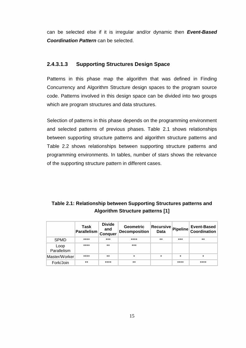
Selection of patterns in this phase depends on the programming environment
and selected patterns of previous phases. Table 2.1 shows relationships
between supporting structure patterns and algorithm structure patterns and
Table 2.2 shows relationships between supporting structure patterns and
programming environments. In tables, number of stars shows the relevance
of the supporting structure pattern in different cases.
Table 2.1: Relationship between Supporting Structures patterns and
Algorithm Structure patterns [1]
Task Parallelism
Divide and
Conquer
Geometric Decomposition
Recursive Data
Pipeline Event-Based Coordination
SPMD **** *** **** ** *** **
Loop Parallelism
**** ** ***
Master/Worker **** ** * * * *
Fork/Join ** **** ** **** ****

16
Table 2.2: Relationship between Supporting Structures patterns and
programming environments [1]
OpenMP MPI Java
SPMD *** **** **
Loop Parallelism **** * ***
Master/ Worker ** *** ***
Fork/Join *** ****
Program Structuring Patterns:
This group contains patterns which are used for structuring the program
source code.
SPMD Pattern, Master/Worker Pattern, Loop Parallelism Pattern and
Fork/Join Pattern are the patterns in this group. Some of these patterns can
be used simultaneously in a program. According to the programming
environment and patterns selected in algorithm structure phase, appropriate
pattern or patterns are selected from this group.
Data Structuring Patterns:
This group contains patterns which are used to structure the data to manage
data dependencies. Shared Data Pattern, Shared Queue Pattern and
Distributed Array Pattern are the patterns in this group.
2.4.3.1.4 Implementation Mechanisms Design Space
In this phase patterns of the previous phases are mapped to the codes for a
specific environment. Methods in this phase can not be considered as design
patterns. But this phase is important to complete the pattern language.
Methods in this phase are UE management, Synchronization and
Communication.
17
UE management:
There are different methods of creation, destruction, and management of the
UEs (processes and threads) for different environments. Threads are created
and destroyed with less cost with respect to he processes.
Synchronization:
Synchronization is very important issue for parallel programming. Because if
task running order change, result of the program may change. For serial
computation ordering is supplied by nature of sequential execution but in
parallel computation more attention must be taken.
Moreover mutual exclusion is necessary to avoid parallel access to the
shared data. If while one task writes to data and another task reads it at the
same time, wrong data is read.
For both synchronization and mutual exclusion, there are different methods
for different environments.
Communication:
Data transfer between the UEs is indispensable for most parallel programs.
Communication mechanism is changed for different environments. Thus
methods for communication are also changed.
2.4.3.1.5 Comments on Parallel Programming Pattern Language
Mattson, Sanders and Massingill’s book [1] was written thanks to many years
of experience of parallel computing. However the pattern language
introduced in this book is not definitively completed but it was a start point for
an iterative process of improvement. In course of time sufficiency of patterns
are expected to be determined by users of this language and missing parts

18
will be removed with some new patterns. [1]
Moreover, patterns in this book are high level patterns which are hard to
learn. This pattern language needs small scaled patterns that support it. Also
there may be some technology dependent and domain dependent patterns
beside the patterns involved in this pattern language. [23]
2.4.3.2 Our Pattern Language (OPL)
(Berkeley Par Lab Pattern Language for Parallel Programming)
OPL (Our Programming Language) developed by Berkeley Par Lab [24] is
another pattern language for parallel programming. This pattern language is
organized with a layered structure and it focuses on patterns for parallel
programming and their usage. Other concepts of computer science are out of
scope of this pattern language. Also OPL is domain independent, i.e., it is
appropriate to application programmers in any field.
2.4.3.2.1 Structure of OPL
OPL is organized with a layered structure that contains five main groups of
patterns. These groups are Architectural patterns, Computational patterns,
Parallel Algorithm strategy patterns, Implementation strategy patterns and
Concurrent execution patterns.
Architectural patterns and Computational patterns layers are at the same
level and there is strong relation between them. An ordinary software
developer visits layers from top to bottom but there can be some back and
forth transitions.

19
2.4.3.2.2 Architectural Patterns:
This group of patterns defines the overall architecture of a program. Patterns
in this group are Pipe-and-filter, Agent and Repository, Process control,
Event based implicit invocation, Model-view-controller, Bulk Iterative,
Map reduce, Layered systems, Arbitrary static task graph.
2.4.3.2.3 Computational Patterns:
Patterns involved in this group define the computations made by components
of the program. Patterns in this group are Backtrack, Banch and bound,
Circuits, Dynamic programming, Dense linear algebra, Finite state
machine, Graph algorithms, Graphical models, Monte Carlo, N-body,
Sparse Linear Algebra, Spectral methods, Structured mesh,
Unstructured mesh.
2.4.3.2.4 Parallel Algorithm Strategy Patterns:
This group is composed of high level strategies for better software to exploit
concurrency. Patterns in this group are Task parallelism, Data parallelism,
Recursive splitting, Pipeline, Geometric decomposition, Discrete event,
Graph partitioning, Digital Circuits.
2.4.3.2.5 Implementation Strategy Patterns:
This group of patterns defines implementation of the parallel program. There
are two types of patterns in this group, namely program structure patterns
and data structure patterns. Program structure patterns that describe
program organization are Single-Program Multiple Data (SPMD), Strict
data parallel, Loop-level parallelism, Fork/join, Master-worker/Task-
queue, Actors, BSP. Also data structure patterns are Shared queue,
Distributed array, Shared hash table, Shared data, Data Locality.

20
2.4.3.2.6 Concurrent Execution Patterns:
Patterns in this group illustrate the mapping of the parallel algorithm to the
program. These patterns are strongly related with hardware and parallel
programming model.
There are two types of patterns in this group. First type is process/thread
control patterns and CSP or Communicating Sequential Processes, Data
flow, Task-graph, Single-Instruction Multiple Data (SIMD), Thread pool,
Speculation are the patterns of this type. The second type is coordination
patterns that include Message passing, Collective communication,
Mutual exclusion, Point to point synchronization, Collective
synchronization, Transactional memory patterns. [24]
2.5 Real Time Performance Metrics
Real time systems are systems that must respond to an event within
operational deadlines. If such a system cannot complete its work before a
deadline then it is said to have failed. Thus correctness of the system
depends not only on the correctness of solution but also response time.
Hard real time systems always require response time within given
constraints. If even the system responds late only once, then it is said to
have failed.
Soft real time systems can tolerate such delays but if these occur
consistently then the system is said to have failed.
A real time system does not necessarily run as fast as possible. But it runs
within deterministic time constraints. These constraints are defined
specifically by system requirements.

21
In real-time embedded systems performance and low power consumption is
very important. Multicore processors are good choices to satisfy these two
criteria.
There are a number of metrics used to measure real time system
performance. According to [25], some metrics to measure performance are
grouped under performance profiles that include constraints that specify the
time spent in functions, A-B timing which is the time between two specified
points, response to external events which is the time between an external
event and system response (e.g. interrupt latency), RTOS task performance
i.e. task deadline performance according to a specific task profile.
In [26], three types of performance metrics for real-time systems are stated:
Qualitative binary criteria (criteria either being fulfilled or not):
o Timeliness, the ability to meet all deadlines
o No unbounded delays nor arbitrarily long executions
o Safety licensable, or better, safety licensed
o Functional correctness
o Deterministic behavior
o Permanent readiness
o Simultaneous operation towards the outside
o All applicable physical constraints met
o Only static and real features used
o Deadlocks prevented
Qualitative gradual criteria (one system may have a property to a
higher degree than another one, but the property cannot be
quantified):
o Safety

22
o Dependability
o Behavioral predictability, even in error situations
o Complexity, or better, simplicity (the simpler the better)
o Reliability
o Robustness
o Fault tolerance
o Graceful degradation upon malfunctions
o Portability
o Flexibility
Quantitative criteria (criteria giving rise to measurable numbers):
o Worst-case response times to occurring events
o Worst-case times to detect and correct errors
o Signal to noise ratio and noise suppression
o MTBF, MTDF, MTTF, and MTTR
o Capacity reserves
o Overall project costs (“the bottom-line”)
For different cases different subset of these metrics can be used. For
example in [27] responsiveness (worst-case time to response time to an
event) and timeliness (worst-case time to process after responding event)
are mentioned as the metrics that determine the system performance.
Beside these real time system performance metrics, there are some
performance metrics for parallel applications such as Sequential Time,
Parallel Time, Critical Path Time, Speed, Speedup, Efficiency, Utilization, and
Total Overhead. [28]
In [1] and in [24], parallel programming patterns from different sources have
been brought together and pattern languages have been introduced. Since
accessing to [1] is easier than accessing to [24] and [1] is well documented

23
than [24], the pattern language in [1] is selected as guide for this thesis.

24
CHAPTER 3
IMPLEMENTATION
In this chapter, implementation of parallel software design for the test project
in the thesis, multicore programming skills, development environment and
test setup are described. The test project is designed both as sequential
program and as parallel program by using the pattern language in [1].
Moreover, the test project is developed with attention to embedded real time
software concerns.
Executable code of the project is run on an embedded environment. Wind
River SBC8641D multicore evaluation board is used as hardware on which
embedded real-time WindRiver VxWorks 6.6 SMP operating system
operates.
Also Wind River WorkBench 3.0 development environment and its tools are
used to develop the test project and to obtain the measurements.
3.1 VxWorks OS & VxWorks 6.6 with SMP
VxWorks is a real time operating system which is developed by WindRiver
Company.
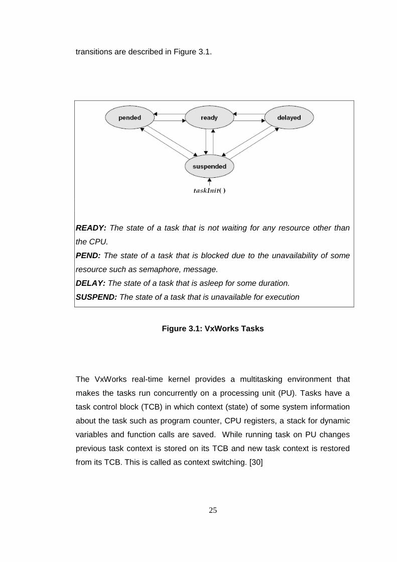
Main unit of execution elements for VxWorks OS are tasks. Task states and
25
transitions are described in Figure 3.1.
READY: The state of a task that is not waiting for any resource other than
the CPU.
PEND: The state of a task that is blocked due to the unavailability of some
resource such as semaphore, message.
DELAY: The state of a task that is asleep for some duration.
SUSPEND: The state of a task that is unavailable for execution
Figure 3.1: VxWorks Tasks
The VxWorks real-time kernel provides a multitasking environment that
makes the tasks run concurrently on a processing unit (PU). Tasks have a
task control block (TCB) in which context (state) of some system information
about the task such as program counter, CPU registers, a stack for dynamic
variables and function calls are saved. While running task on PU changes
previous task context is stored on its TCB and new task context is restored
from its TCB. This is called as context switching. [30]
26
Multitasking on VxWorks OS is performed by two scheduling algorithms:
Preemptive Scheduling: CPU is allocated to the higher priority task
among ready tasks by the preemptive priority-based scheduler.
Round-robin scheduling: CPU is allocated fairly among all ready
tasks of the same priority by executing tasks for same time interval or
time slice.
For VxWorks previous releases until VxWorks 6.6 SMP, although tasks are
seems as they run concurrently, this concurrency was virtual. In fact, at any
moment only one task can be executed and to execute any other task, tasks
must be switched by the operating system.
With VxWorks 6.6 SMP real parallel operating is performed on different cores
of the multicore hardware. At a moment one task can be executed on one
core and another one on another core. Beside this, the multitasking is still
provided on any cores of the hardware.
In VxWorks 6.6 SMP OS with default settings, ready tasks are assigned to
any idle core. But a task can be assigned to a specific core by user. This is
called as CPU affinity.
Mutual exclusion is one of the most important issues for multitasking systems
which means that avoiding the simultaneous use of a common resource by
two execution unit. This resource can be a global variable or a piece of code
called critical sections. Semaphores, message queues, task preemption
locks are standard methods for performing the mutual exclusion in VxWorks
OS.
Beside these methods, some new methods are required for VxWorks SMP to
exploit concurrency and to solve some problems such as memory access

27
disorders which can be occurred only in multicore systems.
Spinlocks: Spinlocks are like semaphore as both usage and
mechanism. But main difference is that while task wait for a spinlock it
does not make state transition from running to pending as in
semaphore. Instead, task spin in a tight loop while it take spinlock.
This is called spinning or busy wait. When spinlock is given by the task
taken it, it is taken immediately by the task make busy wait without any
context switch. Spinlock must be taken for a short and deterministic
period of time because it may make the both PEs (CPU core on which
task that took spinlock run and CPU core on which task making busy
wait to take spinlock run) be busy. Spinlocks must be used carefully to
avoid live locks.
o Live Lock occurs when such a case that task1 took spinlockA
and waits for spinlockB when task2 had taken spinlock B and
waits for spinlockA.
Memory Barrier: Modern CPUs reorder the memory access (read
and write) request. Sometimes this may cause errors. Actually this is
not a problem for unicore CPUs but it is only for multicore CPUs. To
avoid this problem memory barriers which prevents the memory
access reordering are used. Example adapted from [30] shows how
can memory access reorder be problem.
/* CPU 0 - announce the availability of work */
pWork = &work_item; /*store pointer to work item to be performed*/
workAvailable = 1;
/* CPU 1 - wait for work to be performed */
while (!workAvailable);
doWork (pWork); /*error - pWork might not be visible to this CPU yet*/
28
Atomic Operations: Atomic operations are small operations that
atomically access memory. Mutual exclusion is guaranteed while
these operations are made. These operations are add, subtract,
increment, decrement, OR, XOR, AND, NAND, set, clear, compare
and swap. [30]
CPU-Specific Mutual Exclusion: For a specific CPU task switching
can be locked for a time to provide mutual exclusion. [30]
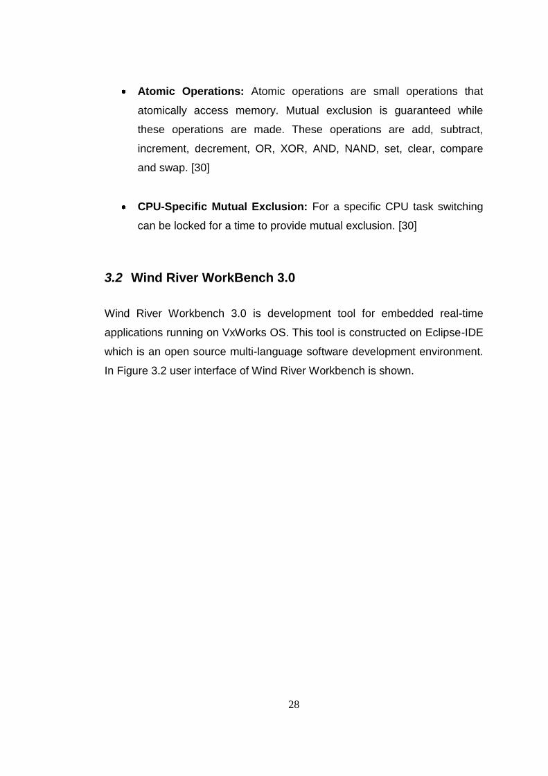
3.2 Wind River WorkBench 3.0
Wind River Workbench 3.0 is development tool for embedded real-time
applications running on VxWorks OS. This tool is constructed on Eclipse-IDE
which is an open source multi-language software development environment.
In Figure 3.2 user interface of Wind River Workbench is shown.

29
Figure 3.2: User Interface of Wind River Workbench
Workbench is not only for developing software but it also supplies some
features to control target by means of its cross development environment
which is defined in [29] as “Cross-development is the process of writing code
on one system, known as a host, that will run on another system, known as a
target”.
Workbench supports some different kinds of project as VxWorks Image
Project, VxWorks Boot Loader/BSP Project, VxWorks Downloadable Kernel
Module Project, VxWorks Real-time Process Project, VxWorks Shared
Library Project, VxWorks ROMFS File System Project, User-Defined Project

30
and Native Application Project. Among these project types VxWorks Image
Project and VxWorks Downloadable Kernel Module Project are used in
thesis. Additionally, VxWorks Boot Loader/BSP Project executable supplied
by Wind River with SBC8641D is also used.
[29]
3.2.1 VxWorks Image Project:
VxWorks kernel image that is booted to the target is configured by VxWorks
Image project. The most appropriate image projects for this thesis were
created and used. Necessary configurations were set to be able measure
performance parameters on running application. Moreover two image
projects were created for thesis. One of them was built as only uniprocessor
(UP) features included in it and other were built with symmetric
multiprocessor (SMP) features addition to the UP features. Other
configuration parameters were kept same between these two projects.
[29]
3.2.2 VxWorks Downloadable Kernel Module Project:
VxWorks Downloadable Kernel Module projects are developed and built to
add its executable into operating system kernel as module. This executables
can be downloaded to and unloaded from target after image boots. Since
these modules are added to the kernel space they can use system resources
directly. Also operating system operations can be called from these modules.
[29] Test program in this thesis were developed as a downloadable kernel
module.

31
3.2.3 Debugger
As well as being a good development tool Workbench also offers a useful
debugger that can be enable to debug kernel tasks and Real-time processes
(RTPs). This debugger supports breakpoints, watching variables and
registers, basic execution control (step into, step over, step out, go, and
stop), advanced execution control (go all, stop all), system and task mode
debugging on SMP systems and most of other debugging issues.
3.2.4 Additional Tools
Moreover thanks to additional tools workbench enable developers to test the
software in early phase of development process.
3.2.4.1 System Viewer
Wind River System Viewer is a logic analyzer that captures interactions
between the operating system, application and target hardware in a time
interval dynamically. These interactions are kernel activities such as
semaphore gives and takes, task spawns and deletions, timer expirations,
interrupts, message queue sends and receives, watchdog time activity,
exceptions, signal activity, system calls, I/O activity, networking activity,
memory allocation, freeing and partitioning, task switch, task states and also
user events coded by user.
After capturing these interactions it can demonstrates the events in timeline,
task by task graph or table. By using this tool race conditions, deadlocks,
CPU starvation, and other problems relating to task interaction can be
detected. [31]
32
3.2.4.2 VxWorks Simulator
The Wind River VxWorks Simulator is a hardware simulator that runs on the
host machine. VxWorks applications can be developed, run, and tested on
host machine without hardware thanks to VxWorks Simulator. VxWorks
Simulator supports most of standard VxWorks features as followings:
Real-Time Processes (RTPs)
Error Detection and Reporting
ISR Stack Protection (Solaris and Linux hosts only)
Shared Data Regions
Shared Libraries (Windows and Linux hosts only)
ROMFS
VxMP (shared-memory objects)
VxFusion (distributed message queues)
Wind River System Viewer
Also simulated hardware supports following features:
a VxWorks console
a system timer
a memory management unit (MMU)—MMU support is required to
take
Advantage of the VxWorks real-time process (RTP) feature.
non-volatile RAM (NVRAM)
virtual disk support—Virtual disk support allows you to simulate a
disk block
device. The simulated disk block device can then be used with any
file system
supported by VxWorks.
a timestamp driver
a real-time clock

33
symmetric multiprocessing (SMP) environment
[32]
Moreover, VxWorks Simulator supports networking application and it can be
used to test complex networking applications. However since it does not
simulates machine-level instructions for a target architecture, it is not suitable
develop hardware device drivers. Also for more accurate SMP simulation
multicore host machine must be used instead of simulator.
In this thesis both UP and SMP VxWorks Simulators are used to test
software in early development phases. Then test program run on real
hardware.
[32]
3.2.4.3 Function Tracer
Wind River Function Tracer is a dynamic execution-tracing tool that monitors
the calls to a traced function while the application runs. It gives the
information about which task make call, which parameters are passed, what
is the return of function and also execution time of call. [33]
In this thesis System Viewer tool is used while coding and testing the
software. VxWorks simulator tool is used to run the executable of the
software in early phases to verify and debug the executable. When source
code is verified at a sufficient depth on the simulator, the real hardware
SBC8641D is replaced with the simulator. Debugger and Function Tracer
tools are frequently used throughout the work to debug the program. Tools
such as Performance profiler, Memory Analyzer, Data Monitor and Code
Coverage Analyzer are not used in this thesis and have not been included in
the review presented above; but they can be useful for parallel programming.
For example Performance profiler can be used to determine the
computationally insensitive parts which are potentially parallelizable in the

34
source code.
3.3 Experiment Setup
Experiment setup in this thesis is formed with two nodes and two connections
between them as shown in Figure 3.3. One node is host machine which is a
standard PC and other is target machine which WindRiver SBC8641D
evaluation board.
Figure 3.3: Experiment Setup
3.3.1 Host Machine
Host machine that is used in this thesis is a standard a computer with Intel
Core2 Quad CPU Q9400 @2.66Hz 1.97Hz, 3.46 GB of RAM. As an OS,
Windows XP is run on the host machine. This machine has one Ethernet port
and one serial port to connect with target.

35
Some necessary programs are installed on the host machine. For this work
an FTP server, an NFS server and Wind River WorkBench will run on host
machine.
Connections with target:
As an FTP server, the FTP server supplied by Wind River in
WorkBench installation directories is used. FTP server is necessary to
boot VxWorks Image which is configured instance of VxWorks OS. To
use this FTP server user rights must be set. Also board must be
configured as to be able to boot from host and user name and
password must be set same as FTP server rights.
WorkBench supplies a useful interface to board by its target server
connection facility. Thanks to target server connection, download a
Kernel Module to the board is very easy as drag and drop. Running
tasks, downloaded modules, vb. can be watched by target server
connection. Also some VxWorks tools such as system viewer,
performance scope, debugger, console, shell vb. can be run owing to
the target server connection. Another feature supplied by target
server connection is The Target Server File System (TSFS). It is a full-
featured, easy to use file system that can be used to mount on host
file system. However since its slow, in this thesis an external NFS
server tool is used. But System Viewer tool actually uses TSFS.
WorkBench also supplies terminal view to open serial connection with
target. Terminal view can be used to watch the output text from target
and to send input text to the target. An alternative program to terminal
is Hyperterminal supplied by Windows XP.

36
As NFS server an open source NFS server Truegrid Pro NFS is used
for this thesis. Thanks to this server some directories on host machine
are exported to the target use. Configuration files are read from these
directories and log files are written to them in this thesis. This program
runs as windows service on the host.
Windows Telnet client is used to input text to board and output text
from board. It is used as an alternative to the terminal feature of
Workbench.
Other Used Programs:
PuTTY:
This tool is described as “PuTTY is a free SSH, Telnet and Rlogin client for
32-bit Windows systems” in its manual. Additionally it can be used to listen
serial channel. This tool can log the output to a specified log file. In this thesis
it is used both serial channel and telnet client.
UltraEdit:
UltraEdit is commercial text editor software. Also it has a useful file
comparison tool. This tool will be used to compare the output log files.
3.3.2 Target Machine
Target machine, namely the hardware that the application will run on is
WindRiver SBC8641D for this thesis.
37
3.3.2.1 Wind River SBC8641D:
The SBC8641D evaluation board is produced by Wind River to enable
software engineers to develop and test parallel applications. This single
board computer is in a 6U form factor and contains the Freescale®
MPC8641D™ dual core processor.
Features available on the SBC8641D evaluation board are listed as
followings:
Freescale MPC8641D processor
2 banks of 256MB of DDR2 SDRAM running at DDR400 speed
(each bank on different DDRMC).
128MB of Local Bus SDRAM using a 100-pin DIMM.
(2) 16MB of on-board Flash memory (Dual boot ROM).
64MB One Nand, Flash File System.
8KB EEPROM.
Four Gigabit Ethernet (GbE) ports via front-panel RJ45 connectors.
Two RS-232 serial communication ports via mini-DB9 connectors.
(2) x8 PCIe connectors
Hard reset switch.
8 user switches.
2x16 LCD character display.
16-pin JTAG header for emulator communication
52-pin Universal Debug header for emulator communication.
[34]
3.3.2.2 Freescale MPC8641D
The MPC8641D is a dual core processor developed by Freescale. This
processor has two 32-bit Power Architecture microprocessor cores e600
38
running at up to 1.5 GHz, two L2 cache for each core, dual 64 bit (72b with
ECC) DDR2 memory controllers which can be assigned to the cores or
shared between them, Dual 8-lane PCI Express ports, 4-lane serial RapidIO
port, four Ethernet controllers supporting QoS and 10 Mbps, 100 Mbps, and
1000 Mbps.
The MPC8641D supports both symmetric multiprocessing (SMP) and
Asymmetric multiprocessing (AMP). [35]
3.4 Test Project
3.4.1 List Management Software:
A dynamically changing list is managed by the test program within real time
constraints. Members of the list that be managed are called ListElements. All
ListElements are specified by an ID and they have three types of specific
parameters and one major parameter. Specific parameters are called
XParameter, YParameter, ZParameter which have similar properties. They
are determined by their values. Each has minimum, maximum, average
values. Major parameter has a single value for each element.
Parameters of a ListElement are measured by some devices. Measurements
are made from some numbers of samples and minimum, maximum and
average values are determined. Then ListElements that parameters values
are determined are sent to the test program by another program via TCP
interface. Any number of ListElements can be sent at one time.
After ListElements reach to the test program, program decides whether newly
received element (RE) can update any present ListElement in the list or it is
new element for the list. This decision is made with update decision
algorithm. If RE can update an existing ListElement than this elements
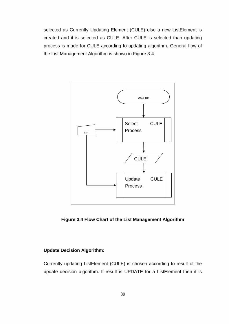
39
selected as Currently Updating Element (CULE) else a new ListElement is
created and it is selected as CULE. After CULE is selected than updating
process is made for CULE according to updating algorithm. General flow of
the List Management Algorithm is shown in Figure 3.4.
Figure 3.4 Flow Chart of the List Management Algorithm
Update Decision Algorithm:
Currently updating ListElement (CULE) is chosen according to result of the
update decision algorithm. If result is UPDATE for a ListElement then it is
RE
Wait RE
Select CULE
Process
Update CULE
Process
CULE
40
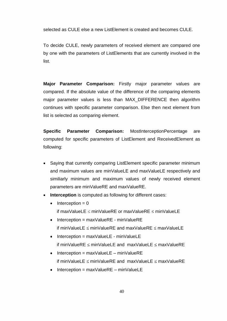
selected as CULE else a new ListElement is created and becomes CULE.
To decide CULE, newly parameters of received element are compared one
by one with the parameters of ListElements that are currently involved in the
list.
Major Parameter Comparison: Firstly major parameter values are
compared. If the absolute value of the difference of the comparing elements
major parameter values is less than MAX_DIFFERENCE then algorithm
continues with specific parameter comparison. Else then next element from
list is selected as comparing element.
Specific Parameter Comparison: MostInterceptionPercentage are
computed for specific parameters of ListElement and ReceivedElement as
following:
Saying that currently comparing ListElement specific parameter minimum
and maximum values are minValueLE and maxValueLE respectively and
similiarly minimum and maximum values of newly received element
parameters are minValueRE and maxValueRE.
Interception is computed as following for different cases:
Interception = 0
if maxValueLE minValueRE or maxValueRE minValueLE
Interception = maxValueRE - minValueRE
if minValueLE minValueRE and maxValueRE maxValueLE
Interception = maxValueLE - minValueLE
if minValueRE minValueLE and maxValueLE maxValueRE
Interception = maxValueLE – minValueRE
if minValueLE minValueRE and maxValueLE maxValueRE
Interception = maxValueRE – minValueLE

41
if minValueRE minValueLE and maxValueRE maxValueLE
Maximum Interception Percentage = 100 * maximum of
Interception/(maxValueLE - minValueLE) and Interception/(maxValueRE -
minValueRE)
If Maximum Interception Percentage values for all three parameters are
greater than MIN_INTERCEPTION_PERCENTAGE then ListElement is
selected as CULE. Else then next element from list is selected as comparing
element.
Beside this X, Y and Z parameter comparison algorithm, also some other
algorithms may be possible with different methods. Some methods may be
use parameter history list. Thus process time for the method is changed with
the selected MAX_HISTORY_LENGTH constant. Since main focus of this
thesis is not related with the selected methods, in test program this part of
algorithm is replaced with a TimeKiller function that uses the CPU for a given
time named as killtime. Tests are made for different killtime values to
simulate different methods and different MAX_HISTORY_LENGTH constant
values.
After major parameter and X, Y, Z parameter comparison, if more than one
element are decided as CULE candidate then major parameters of these
candidates are compared and one that has nearest major parameters value
to the RE major parameter value, is selected as CULE.
If all ListElements compared and CULE is not determined yet then new
ListElement is created and selected as CULE.
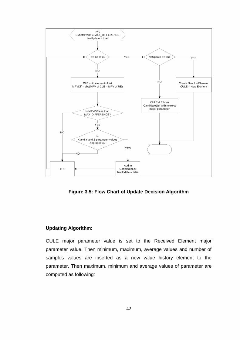
In Figure 3.5 the flow chart of the Update Decision Algorithm is presented.
42
i = 0
CMinMPVDif = MAX_DIFFERENCE
NoUpdate = true
i == no of LE
CLE = ith element of list
MPVDif = abs(MPV of CLE – MPV of RE)
Is MPVDif less than
MAX_DIFFERENCE?
Is
X and Y and Z parameter values
Appropriate?
Add to
CandidateList
NoUpdate = false
i++
NoUpdate == true
Create New ListElement
CULE = New Element
CULE=LE from
CandidateList with nearest
major parameter
NO
YES
YES
NO
NO
YES
NO
YES
Figure 3.5: Flow Chart of Update Decision Algorithm
Updating Algorithm:
CULE major parameter value is set to the Received Element major
parameter value. Then minimum, maximum, average values and number of
samples values are inserted as a new value history element to the
parameter. Then maximum, minimum and average values of parameter are
computed as following:

43
maxValue = maximum value among the value history elements max
values.
minValue = minimum value among the value history elements max
values.
avgValue = summation of multiplication of average value and number of
samples divided by summation of number of samples among the value
history elements.
After these update algorithm some other extra analysis on the list can be
made. This analysis processing time is changed with the list length or with
MAX_HISTORY_LENGTH constant. Since main focus of this thesis is not
related with these analysis methods, in test program this part of algorithm is
replaced with an TimeKiller function that uses the CPU for a given time.
In Figure 3.6 Flow Chart of the Updating Algorithm is demonstrated.

44
Figure 3.6: Flow Chart of Updating algorithm
45
3.4.2 Design of Parallel Test Software:
Parallel software design for the test project is made by using the pattern
language in [1]. According to the pattern language in [1] there are four design
phases that must sequentially be passed through by designer. Below, each
phase shall be described in succession. In each phase, three different design
approaches shall be considered.
In advance, it must be stated that the unit of execution (UE) is the task itself
for the purposes of this thesis because the running program will execute on
VxWorks OS as a downloadable kernel module.
3.4.2.1 Finding Concurrency Phase
According to the pattern language introduced in [1], first step to solve a
problem as parallel is finding the concurrency in the problem.
Unfortunately the problem that is tried to solve in this thesis, does not have
any parallelism that can be seen obviously. However some parts can be still
make parallel.
At first sight, algorithm that is mentioned in 3.4.1 includes two main tasks.
First one is update decision task which determines the CULE and second
task is updating task that updates the parameters of the CULE with the
parameters of the RE.
As for data, two main data are available in this problem, which are current list
of LEs and the list of REs.
According the pattern language in [1] there are some forces in finding

46
concurrency patterns that the software designer must consider. One of these
forces is flexibility. Parallel software design must be as flexible as it can be
adapted to another hardware which has different architecture, different
number of processors and different types of data sharing mechanisms.
Another force is efficiency. Parallel software design is efficient if exploited
concurrency is greater than work done to make design parallel. Number and
size of tasks and data must be adequate to exploit concurrency by to make
all PEs busy. Otherwise overhead of design (too much task switching,
synchronization, communication etc) may bring about less performance
respect to the serial program performance. Another force is simplicity. Design
must be simple enough to be handled and complex enough to be run as
parallel. However flexibility and efficiency may sometimes bring about some
complexity.
Also design must be suitable for the hardware on which software run.
Number of PE is an important hardware feature. Design must be made as
ideally all PEs be used during runtime. Another important issue that must be
considered is the data sharing mechanism on the hardware to make
appropriate data decomposition.
Hardware on which test application in this thesis runs is a dual core
processor. Thus it has two PEs. Also hardware is used as an SMP system.
Therefore data sharing is performed by shared memory mechanism. These
hardware features must be considered while parallel software design is being
made.
Implementation of the list management algorithm can be made with three
different parallel design approaches.

47
3.4.2.1.1 Design Approach 1:
One possible parallel programming design for list updating problem can be
made as decompose the update decision task and updating task into small
tasks as they process on only one parameter of the list elements. Also
unfortunately there must be other tasks that run as sequential. These tasks
are major element comparing task and new element creation task.
Tasks: Tasks in this approach are listed below.
Task0: Major parameter comparing task
◦ This task runs as sequential and it decides whether the major
parameters of the RE and CLE are appropriate to update or not.
◦ Major parameters of the ith RE and the kth LE are data accessed by
this task. These data are read only for this task.
Task1: X parameter comparing task
◦ This task decides whether the X parameters of the RE and CLE
are appropriate to update or not.
◦ X parameters of the ith RE and the kth LE are data accessed by this
task. These data are read only for this task.
Task2: Y parameter comparing task
◦ This task decides whether the Y parameters of the RE and CLE
are appropriate to update or not.
◦ Y parameters of the ith RE and the kth LE are data accessed by this
task. These data are read only for this task.
Task3: Z parameter comparing task
◦ This task decides whether the Z parameters of the RE and CLE
are appropriate to update or not.

48
◦ Z parameters of the ith RE and the kth LE are data accessed by this
task. These data are read only for this task.
Task4: New list element creating task
◦ This task runs as sequential and it creates a new list element with
default parameters.
◦ Data for this task is the new list element and it is set as CULE.
Thus this data is read/write for this task.
Task5: X parameter updating task
◦ This task updates the X parameter of CULE by using X parameter
of RE.
◦ X parameters of the ith RE and the kth LE are data accessed by this
task. X parameter of the ith RE is read only and X parameter of the
kth LE is read/write for this task.
Task6: Y parameter updating task
◦ This task updates the Y parameter of CULE by using Y parameter
of RE.
◦ Y parameters of the ith RE and the kth LE are data accessed by this
task. Y parameter of the ith RE is read only and Y parameter of the
kth LE is read/write for this task.
Task7: Z parameter updating task
◦ This task updates the Z parameter of CULE by using Z parameter
of RE.
◦ Z parameters of the ith RE and the kth LE are data accessed by this
task. Z parameter of the ith RE is read only and Z parameter of the
kth LE is read/write for this task.
Data: Data in this approach are listed below.
49
major parameter of each RE and LE
X, Y, Z parameters of each RE and LE
X, Y, Z parameters of CULE
Task Groups: Tasks in this approach can be grouped according to their
execution order. Tasks that run as parallel are placed in same group. Task
groups in this approach are listed below.
TaskGroup1: includes Task1, Task2 and Task3.
TaskGroup2: includes Task5, Task6 and Task7.
Since Task0 and Task4 are run as sequential they are not placed in a
group
Task Group Orderings:
Task group ordering for this approach is shown in Figure 3.7.
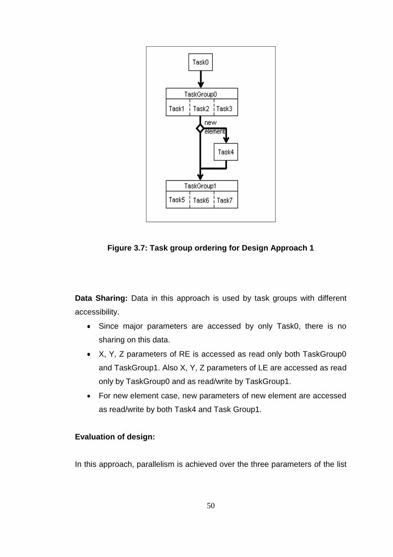
50
Figure 3.7: Task group ordering for Design Approach 1
Data Sharing: Data in this approach is used by task groups with different
accessibility.
Since major parameters are accessed by only Task0, there is no
sharing on this data.
X, Y, Z parameters of RE is accessed as read only both TaskGroup0
and TaskGroup1. Also X, Y, Z parameters of LE are accessed as read
only by TaskGroup0 and as read/write by TaskGroup1.
For new element case, new parameters of new element are accessed
as read/write by both Task4 and Task Group1.
Evaluation of design:
In this approach, parallelism is achieved over the three parameters of the list
51
elements. Thus for this design three tasks can be run as parallel. Since there
are only two PEs on the test hardware, only two tasks can be run as parallel
during the runtime. While third task run on one PE, other PE becomes idle. If
hardware would have three PEs, this design would be very appropriate. But if
hardware would have more than three PEs then still some PEs would be idle.
Therefore, this design is not flexible enough.
Since all data are accessed as read only or different date are written by
different tasks except new element case, there is no mutual exclusion
mechanism needed on data. For new element case parameters of new
element are written by both Task4 and Taskgroup1. In fact for this element
case, Task4 and TaskGroup1 run as sequential there is still no need to use a
mutual exclusion mechanism on data.
Task0, TaskGroup0, Task4 and TaskGroup1 must be synchronized to run as
shown in Figure 3.7.
3.4.2.1.2 Design Approach 2:
Another design approach to solve this problem can be made as making the
two main tasks i.e. update decision task and updating task run as parallel.
While CULE is updating with the kth RE on one PE simultaneously update
decision task is run on other PE for (k+1)th RE. Also new element creating
task is needed for new element case and this task run as sequential.
Tasks: Tasks in this approach are listed below.
Task0: Update decision task
◦ This task finds the list element which is appropriate to update with
the RE ie. it finds the CULE.
◦ The ith RE and the kth LE are data accessed by this task. These

52
data are read only for this task.
Task1: Updating task
◦ This task updates the parameters of CULE found by Task0 or new
element with the parameters of the RE.
◦ The ith RE and the CULE are data accessed by this task. The ith RE
is read only and CULE is read/write for this task.
Data: Data in this approach are listed below.
each RE
each LE
CULE
Task Groups: There is no need to group tasks for this approach.
Task Group Orderings:
While Task0 is run on one PE for (i+1)th, simultaneously Task1 can
run on another PE for ith PE as parallel.
Data Sharing:
REs are accessed as read only by both Task0 and Task1.
LEs are accessed as read only by Task0 but as read/write by Task1.
For new element case, new parameters of new element are accessed
as read/write by both Task1 and Task1.
Evaluation:
There only two parallel tasks in this approach so it is not appropriate for
hardware having more than two PEs. Thus this design is not flexible.
If one task lasts longer than the other, PE on which fast task run become idle
until the slow task finishes its run. This affects the efficiency.

53
While Task1 updates the CULE with ith RE, Task0 searches for appropriate
LE to update with (i+1)th RE simultaneously. Therefore, for currently updating
LE (CULE), protection is needed to avoid misread of the data.
3.4.2.1.3 Design Approach 3:
Another parallel design can be made as parallelizing loop works. LE list can
be divided into equal parts. Update decision task and updating task run as
sequentially on all PEs over the different parts of the data at the same time.
Tasks: Tasks in this approach are listed below.
Task0: Update decision task
◦ This task finds the list element which is appropriate to update with
the RE i.e. it finds the CULE.
◦ The ith RE and the some part of the current list are data accessed
by this task. These data are read only for this task.
Task1: New list element creating task
◦ This task runs as sequential and it creates a new list element with
default parameters.
◦ Data for this task is the new list element and it is set as CULE.
Thus this data is read/write for this task.
Task2: Updating task
◦ This task updates the parameters of CULE found by Task0 or new
element created by Task1, with the parameters of the RE.
◦ The ith RE and the CULE are data accessed by this task. The ith RE
is read only and CULE is read/write for this task.

54
Data:
each RE
some parts of LE list
Task Groups: Task1 and Task2 run as sequential on each PE. Maybe they
can be grouped together as TaskGroup1.
Task Ordering:
Same Task0 can run on different PEs over different parts of the LE list
as parallel. TaskGroup1 has the serial tasks of this design can run on
any PE after Task0 finishes its work.
Data Sharing:
Each TaskGroup1 accessed on RE as read only and different parts of
the LE list as read/write.
Evaluation:
Since the LE list can be divided into any number of parts this design is
flexible i.e. it can be adapted to the hardware having different number of PEs.
Efficiency depends on the partitions of the LE list. The most efficient design
can be made by fairly partitioning.
Parallelism is on only Update Decision part of the algorithm. The other part is
serial for this design and a synchronization mechanism is needed betwwen
Task0 and TaskGroup1.
55
3.4.2.2 Algorithm Structure Phase
According to the pattern language introduced in [1], after finding tasks, data,
task groups, task orderings and data dependencies, designing procedure
continues with algorithm structure phase. In this phase, design is refined and
moved closer to the program.
There are also some forces that must be considered while making the
design. Efficiency and simplicity are two forces for this phase as for finding
concurrency phase. Portability is another force which addresses that same
software can be run on different platforms. Another force is scalability which
requires software that can be run on platforms that has different number of
PEs.
Most important issue for this design phase is to choose right patterns to the
problem. The major organizing principle and features of the target platform
affect the choice. Major organizing principle is determined according to the
concurrency in the problem. If concurrency is on task than major organizing
principle is organization by tasks, if it is on data then major organizing
principle is organization by data or if it is on flow of data then major
organizing principle is organization by flow of data. After determining the
major organizing principle in the problem then patterns are chosen according
to the features of the tasks, data or flow of data. [1] Also while making
decision for right pattern, some features of target platform must be
considered. Features like memory sharing mechanism, communication
mechanism or number of UEs supported by hardware are important for right
decision.

56
3.4.2.2.1 Design Approach 1:
In this approach there are two tasks that run as sequential and two task
groups that both includes three tasks that run as parallel. Parallel tasks are
also embarrassingly parallel i.e. there are no data dependencies between
them. Therefore obviously major organizing principle fort his approach is
organization by tasks. Also since according to [1] tasks in this approach are
enumerated as linear, Task Parallelism pattern is selected.
According to the task parallelism pattern task definitions, dependencies
among tasks and scheduling are important issues. Task definitions in this
approach are as mentioned in finding concurrency phase. Also there are no
dependencies among the tasks that run as parallel. As to scheduling, there
are three parallel tasks but only two PEs in the target used for this thesis.
Therefore two tasks must be assigned to one PE and remaining one to other.
Unfortunately this brings about a bad load balancing. This assignment is
made by statically by using CPU affinity feature of VxWorks or it may be
done by VxWorks OS as dynamically during runtime.
Moreover it must be pointed that although parallel tasks do not accessed
same data i.e. X parameter, Y parameter and Z parameter for this approach,
they all accessed the list element structure which involves these three
parameters. Since target used for this thesis supports the shared memory
there is no need to replicate the data. If target would not support sharing
memory and communication would be poor between PEs, it might be needed
to replicate X parameter, Y parameter and Z parameter for tasks for better
performance.

57
3.4.2.2.2 Design Approach 2:
In this approach there are two tasks run as parallel. LE list is the data that is
used by this two parallel task. Firstly Task0 finds the CULE and then task1
updates it. Therefore a data flow is present between parallel tasks in this
approach. Thus major organizing principle for this approach is organization
by flow of data. Although at first sight pipeline pattern is seem to be
appropriate, after more thinking on problem event based coordination pattern
becomes better because pipeline pattern requires one direction flow of data.
However while Task1 is updating the CULE, simultaneously Task0 may try to
compare RE and CULE that is being written by Tasks0. For this case Task1
must notify Task0 after update of CULE is finished. Therefore event based
coordination pattern is better choice.
Since in this approach there are two parallel tasks and target in this thesis
has two PE, this approach is suitable for the target. However it is not scalable
and portable for targets which have more than two PEs.
3.4.2.2.3 Design Approach 3:
In this approach, there is one task that runs as sequential and a task group
with two tasks runs as sequential. Parallel task namely Task0 can run on all
PEs over different part of the current list. Therefore for this approach major
organizing principle is organizing by data. Also since LE list in this problem
does not have a recursive data structure geometric decomposition pattern is
selected for this approach.
Since Task0 can run on different PEs and do not need to access part of data
other than its part, part of data can be distributed to PEs. But if overhead is
tolerable shared memory can also be used and data is placed to the shared
58
memory.
To guarantee the better load balancing between the UEs list elements can be
divided into parts with equal size for each PE.
Since target used for this thesis has two PEs dividing LE list into two equal
parts is appropriate. Also for targets which have different number of PEs LE
list can be divided into number of PEs. Therefore this approach is scalable
for different number of PEs.
3.4.2.3 Supporting Structure Phase
According to the pattern language introduced in [1], Supporting Structure
Phase is the next phase after Algorithm Structure Phase. This phase is the
bridge between problem domain and software domain. Generally this phase
contains two groups of patterns. Program Structure Patterns are first group
and they are about structure of the source code. Data Structures are the
second group and patterns in this group is about the managing the data
dependencies.
Some forces must be considered while choosing the patterns in this phase.
First of all “clarity of abstraction” is an important force. Source code must be
clear enough to understand. Sequential equivalence is another force which
addresses the consistency between the result of the sequential and parallel
design. Also “environmental affinity” which is alignment of program onto the
used hardware environment is important force to be considered. Additionally
scalability, maintainability and efficiency are forces for this phase.
Patterns that are chosen in previous two phase and the environment or
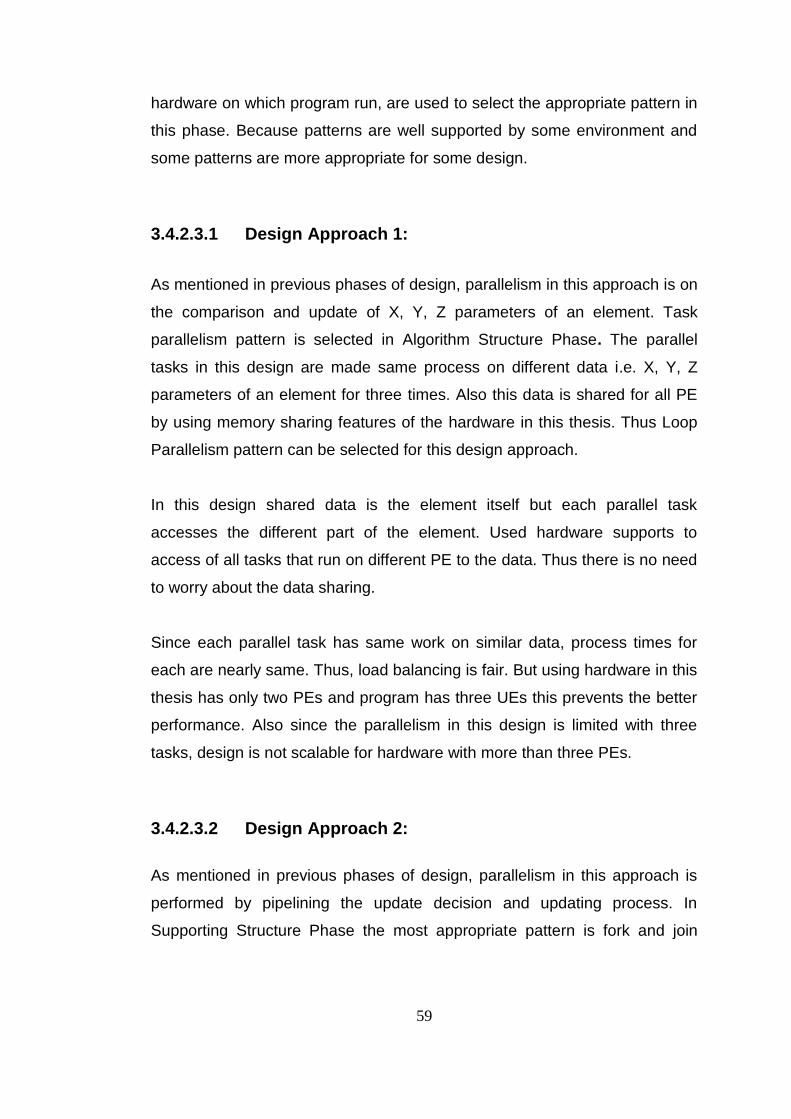
59
hardware on which program run, are used to select the appropriate pattern in
this phase. Because patterns are well supported by some environment and
some patterns are more appropriate for some design.
3.4.2.3.1 Design Approach 1:
As mentioned in previous phases of design, parallelism in this approach is on
the comparison and update of X, Y, Z parameters of an element. Task
parallelism pattern is selected in Algorithm Structure Phase. The parallel
tasks in this design are made same process on different data i.e. X, Y, Z
parameters of an element for three times. Also this data is shared for all PE
by using memory sharing features of the hardware in this thesis. Thus Loop
Parallelism pattern can be selected for this design approach.
In this design shared data is the element itself but each parallel task
accesses the different part of the element. Used hardware supports to
access of all tasks that run on different PE to the data. Thus there is no need
to worry about the data sharing.
Since each parallel task has same work on similar data, process times for
each are nearly same. Thus, load balancing is fair. But using hardware in this
thesis has only two PEs and program has three UEs this prevents the better
performance. Also since the parallelism in this design is limited with three
tasks, design is not scalable for hardware with more than three PEs.
3.4.2.3.2 Design Approach 2:
As mentioned in previous phases of design, parallelism in this approach is
performed by pipelining the update decision and updating process. In
Supporting Structure Phase the most appropriate pattern is fork and join
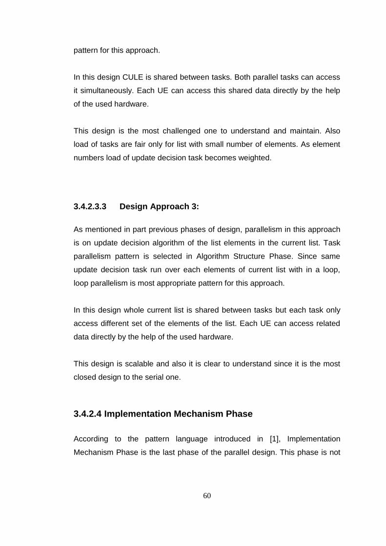
60
pattern for this approach.
In this design CULE is shared between tasks. Both parallel tasks can access
it simultaneously. Each UE can access this shared data directly by the help
of the used hardware.
This design is the most challenged one to understand and maintain. Also
load of tasks are fair only for list with small number of elements. As element
numbers load of update decision task becomes weighted.
3.4.2.3.3 Design Approach 3:
As mentioned in part previous phases of design, parallelism in this approach
is on update decision algorithm of the list elements in the current list. Task
parallelism pattern is selected in Algorithm Structure Phase. Since same
update decision task run over each elements of current list with in a loop,
loop parallelism is most appropriate pattern for this approach.
In this design whole current list is shared between tasks but each task only
access different set of the elements of the list. Each UE can access related
data directly by the help of the used hardware.
This design is scalable and also it is clear to understand since it is the most
closed design to the serial one.
3.4.2.4 Implementation Mechanism Phase
According to the pattern language introduced in [1], Implementation
Mechanism Phase is the last phase of the parallel design. This phase is not
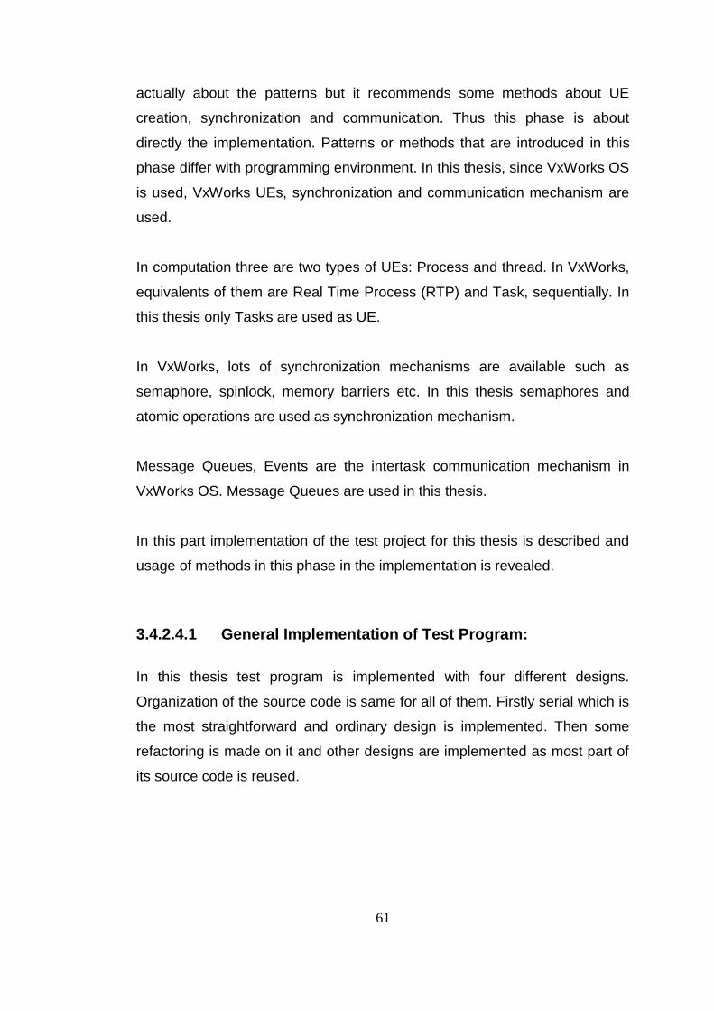
61
actually about the patterns but it recommends some methods about UE
creation, synchronization and communication. Thus this phase is about
directly the implementation. Patterns or methods that are introduced in this
phase differ with programming environment. In this thesis, since VxWorks OS
is used, VxWorks UEs, synchronization and communication mechanism are
used.
In computation three are two types of UEs: Process and thread. In VxWorks,
equivalents of them are Real Time Process (RTP) and Task, sequentially. In
this thesis only Tasks are used as UE.
In VxWorks, lots of synchronization mechanisms are available such as
semaphore, spinlock, memory barriers etc. In this thesis semaphores and
atomic operations are used as synchronization mechanism.
Message Queues, Events are the intertask communication mechanism in
VxWorks OS. Message Queues are used in this thesis.
In this part implementation of the test project for this thesis is described and
usage of methods in this phase in the implementation is revealed.
3.4.2.4.1 General Implementation of Test Program:
In this thesis test program is implemented with four different designs.
Organization of the source code is same for all of them. Firstly serial which is
the most straightforward and ordinary design is implemented. Then some
refactoring is made on it and other designs are implemented as most part of
its source code is reused.

62
3.4.2.4.2 Serial Design:
Implementation is made with object oriented approach. First problem is
analyzed and the class in the problem, required attributes and operations for
the classes and relations between the classes are determined. Then class
diagram in Figure 3.8 is obtained.
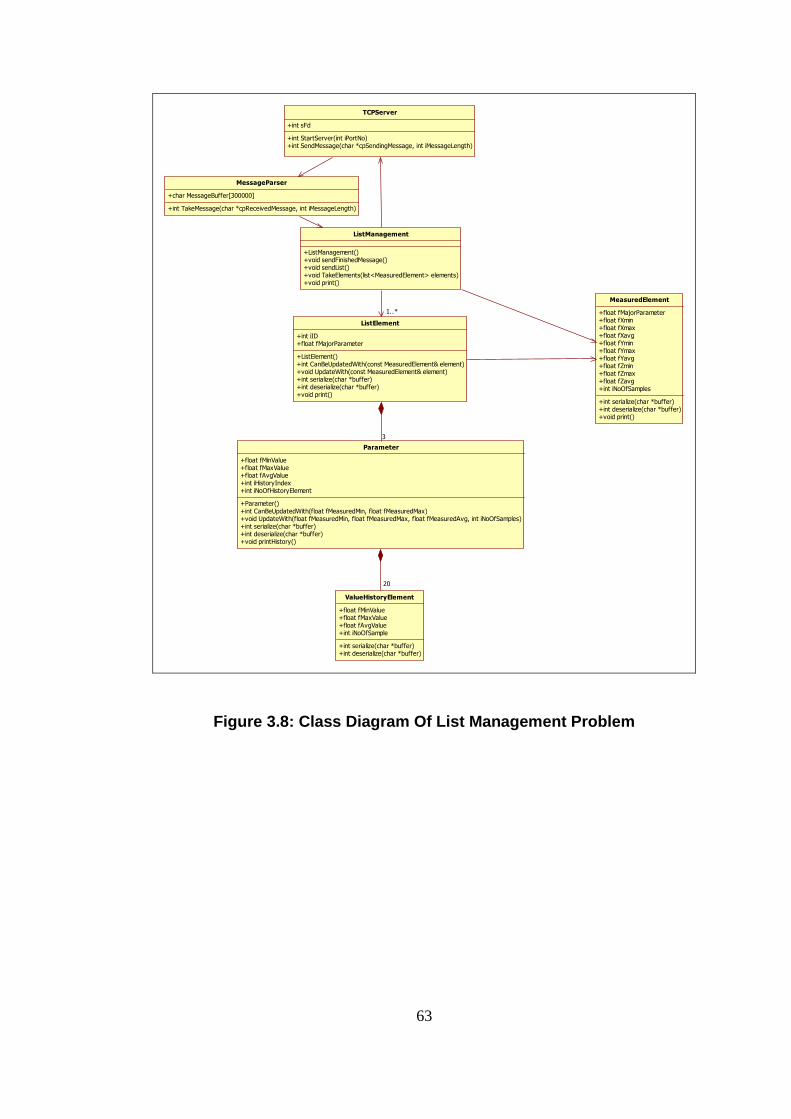
63
TCPServer
+int sFd
+int StartServer(int iPortNo)+int SendMessage(char *cpSendingMessage, int iMessageLength)
MessageParser
+char MessageBuffer[300000]
+int TakeMessage(char *cpReceivedMessage, int iMessageLength)
ListManagement
+ListManagement()+void sendFinishedMessage()+void sendList()+void TakeElements(list<MeasuredElement> elements)+void print()
ListElement
+int iID+float fMajorParameter
+ListElement()+int CanBeUpdatedWith(const MeasuredElement& element)+void UpdateWith(const MeasuredElement& element)+int serialize(char *buffer)+int deserialize(char *buffer)+void print()
Parameter
+float fMinValue+float fMaxValue+float fAvgValue+int iHistoryIndex+int iNoOfHistoryElement
+Parameter()+int CanBeUpdatedWith(float fMeasuredMin, float fMeasuredMax)+void UpdateWith(float fMeasuredMin, float fMeasuredMax, float fMeasuredAvg, int iNoOfSamples)+int serialize(char *buffer)+int deserialize(char *buffer)+void printHistory()
ValueHistoryElement
+float fMinValue+float fMaxValue+float fAvgValue+int iNoOfSample
+int serialize(char *buffer)+int deserialize(char *buffer)
MeasuredElement
+float fMajorParameter+float fXmin+float fXmax+float fXavg+float fYmin+float fYmax+float fYavg+float fZmin+float fZmax+float fZavg+int iNoOfSamples
+int serialize(char *buffer)+int deserialize(char *buffer)+void print()
3
20
1..*
Figure 3.8: Class Diagram Of List Management Problem
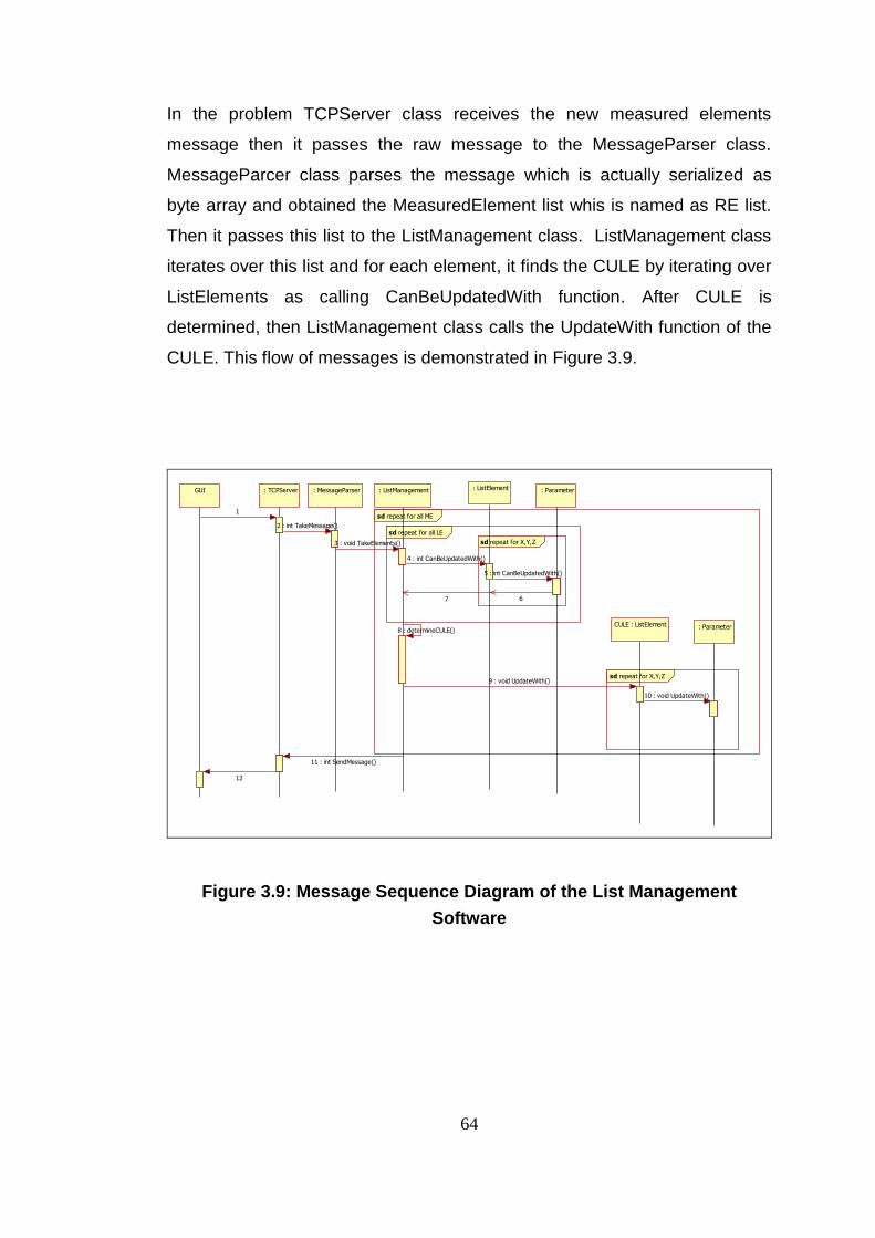
64
In the problem TCPServer class receives the new measured elements
message then it passes the raw message to the MessageParser class.
MessageParcer class parses the message which is actually serialized as
byte array and obtained the MeasuredElement list whis is named as RE list.
Then it passes this list to the ListManagement class. ListManagement class
iterates over this list and for each element, it finds the CULE by iterating over
ListElements as calling CanBeUpdatedWith function. After CULE is
determined, then ListManagement class calls the UpdateWith function of the
CULE. This flow of messages is demonstrated in Figure 3.9.
repeat for X,Y,Zsd
repeat for all LEsd
repeat for X,Y,Zsd
repeat for all MEsd
: TCPServer : MessageParser : ListManagement : ListElement : Parameter
CULE : ListElement : Parameter
GUI
1
2 : int TakeMessage()
3 : void TakeElements()
4 : int CanBeUpdatedWith()
5 : int CanBeUpdatedWith()
67
8 : determineCULE()
9 : void UpdateWith()
10 : void UpdateWith()
11 : int SendMessage()
12
Figure 3.9: Message Sequence Diagram of the List Management
Software

65
After determining the classes and message sequence in the problem, these
structures are declared implemented in appropriate C++ header and source
files. At the end the following files are written:
Starter.cpp: source file including the main function for the problem.
MessageParser.h, Connection.h and Connection.cpp: header and
source files including the declaration and implementation of the
TCPServer and MessageParser classes. Also WaitMessage function
which is entry point of the unique task of serial design implemented in
Connection.cpp file.
ListManagement.h and ListManagement.cpp: header and source
files including the declaration and implementation of the
ListManagement class.
Structures.h and Structures.cpp: header and source files including
the declaration and implementation of the ListElement, Parameter and
ValueHistoryElement classes.
MeasuredElement.h and MeasuredElement.cpp: header and
source file including the declaration and implementation of the
MeasuredElement class.
CommonFunctions.h and CommonFunctions.cpp: header and
source file including some common functions which are used in
different part of the algorithm by different classes.
Implementation Mechanism Pattern Usage:
Since in serial design there is only one task and all process is made as
serially any pattern or method is not required to use.
3.4.2.4.3 Design Approach 1:
Implementation of this design is made by using the serial design
66
implementation. Some part of the source code of serial design is
refactored and some new codes are added. Changed files are Structure.h
and Structures.cpp because the parallelism in this design is on the
Parameter class CanBeUpdatedWith and UpdateWith functions which are
called by ListElement class. Additionally, two new files ParallelTasks.h
and ParallelTasks.cpp are added. Tasks, synchronization and
communication objects are declared and created in these new files.
As mentioned in previous phases in this design there are two task groups
and each has three parallel tasks. Also the main task in the serial design
is kept. Serial works in this design are made by main task. Thus totally
there are 7 tasks in this design. These tasks are named as tTCPServer
(main task), tCBUX, tCBUY, tCBUZ update decision tasks, tUX, tUY, tUZ
updating tasks.
Also there are no data sharing in this design because all parallel tasks
access different part of the common data i.e. instances of
MeasuredElement and ListElement classes. But to synchronize the tasks
a common counter is used between tasks in this design.
Implementation Mechanism Pattern Usage:
UE Management: In this design UEs are VxWorks tasks. All 7
tasks are created at the start of the algorithm. Then they are used
throughout the program running. Therefore, tasks creation and
deletion overhead is prevented.
Synchronization: Main task and update decision tasks must be
synchronized because after parameter comparison is made main
task continue to select CULE. For this synchronization a

67
semaphore “semCBU” is used. When tCBUX, tCBUY, tCBUZ start
the computation, main task requires to take the semCBU and waits
in pending state until it is given. After all of tCBUX, tCBUY, tCBUZ
tasks finish the computation, semCBU is given and main task
continues to execute. The last executing task among tCBUX,
tCBUY, tCBUZ must give this semaphore. To determine if running
task is last or not, a global integer counter is used. At the end of
commutations, task increments this counter and reads the value of
it. If value is less than three, task finishes its work but if value is 3
then task clears the counter, give semCBU semaphore and
finishes the work. Since all tCBUX, tCBUY, tCBUZ tasks read and
write this counter it must be mutually excludes. This is made by
using atomic memory operation, actually atomizing operation of
VxWorks.
Similarly another semaphore “semU” is used to synchronize the
main and tUX, tUY, tUZ tasks. Also a global counter is used with
the same methods while CULE is updating.
Communication: REs are received by the main task. Thus first
running task is main task. But algorithm is run on other tasks. For
update decision, tCBUX, tCBUY, tCBUZ tasks must compare the
related parameter of the RE and LE. Thus main task must send
these parameters to the related task. This communication between
main task and tCBUX, tCBUY, tCBUZ tasks is managed by
message queue mechanism of VxWorks. For each communication
channel one queue is created. Therefore for update decision tasks
three message queues maned as mqCBUX, mqCBUY, mqCBUZ,
are created. Normally tCBUX, tCBUY, tCBUZ tasks wait in pending
state until they receive a message from main task. When main task
sends a message to a queue, related task receives the message

68
and starts to execute.
Similarly for communications between main task and tUX, tUY, tUZ
tasks another three queues named as mqUX, mqUY, mqUZ, are
created.
3.4.2.4.4 Design Approach 2:
Implementation of this design is made by using the serial design
implementation. Some part of the source code of serial design is
refactored and some new codes are added. Changed files are
ListManagement.h and ListManagement.cpp because the parallelism in
this design is on the ListElement class CanBeUpdatedWith and
UpdateWith functions which are called by ListManagement class.
Additionally, two new files ParallelTasks.h and ParallelTasks.cpp are
added. Tasks, synchronization and communication objects are declared
and created in these new files.
As mentioned in previous phases in this design there are two tasks:
tFCULE task which finds the CULE and tUCULE task which updates the
CULE. Also the main task in the serial design is kept.
The CULE is the shared data for this design because while tUCULE task
access to CULE for writing and tFCULE task can read it.
Implementation Mechanism Pattern Usage:
UE Management: In this design UEs are VxWorks tasks. All 3
tasks are created at the start of the algorithm. Then they are used
throughout the program running. Therefore, tasks creation and
deletion overhead is prevented.

69
Synchronization: In three parts of this design, synchronization
mechanisms are required.
First one is required to synchronize main task and tFCULE task.
When main task sends a RE to tFCULE, main task requires taking
the semFindCULE semaphore and waits in pending state until it is
given. When tFCULE is finds the CULE it gives the semFindCULE
and main task continues to execute and sends the RE to tUCULE
task.
Second one is required to synchronize tUCULE task and tFCULE
task. tFCULE task start to search for CULE by iterating over the
current LE list. But when iterator is the CULE it passes it and when
it reaches the end of the list, it requires taking the
semCULEIsUpdating semaphore and waits in pending state until it
is given. When tUCULE finishes the CULE updating it gives the
semCULEIsUpdating semaphore and tFCULE task continues to
execute and make comparison with RE and previous CULE
Last one is required to synchronize main task and tUCULE task for
the last RE. Since after all REs are processes main task sends a
just finished message to the RE source from TCP Interface, it must
wait the last updating to send this message. Thus when main task
sends to the last RE to tUCULE task, it requires to take the
semFinishIsWaiting semaphore and waits in pending state until it is
given. When tFCULE task finishes the updating for last element it
gives the semFinishIsWaiting semaphore and main task continues
to execute and sends just finished message.
Communication: RE list are received by the main task. Thus first

70
running task is main task. But algorithm is run on other tasks. For
update decision tFCULE must compare the RE and LEs. Thus
main task must send the RE and the current LE list to tFCULE
task. This communication between main task and tFCULE task is
managed by message queue mechanism of VxWorks and a
meesage queue named as mqFindCULE is created. Normally
tFCULE task waits in pending state until it receives a message
from main task. When main task sends a message to the queue
tFCULE task receives the message and start to execute.
Similarly, main task must send RE and the information about this
measured element is last one or not, to the tUCULE task by using
another message queue named as mqUpdateCULE.
3.4.2.4.5 Design Approach 3:
Implementation of this design is made by using the serial design
implementation. Some part of the source code of serial design is
refactored and some new codes are added. Changed files are
ListManagement.h and ListManagement.cpp because the parallelism in
this design is on iterations of the ListElements in the current LE list.
Additionally, two new files ParallelTasks.h and ParallelTasks.cpp are
added. Tasks, synchronization and communication objects are declared
and created in these new files.
As mentioned in previous phases in this design there are can be as many
parallel tasks as the number of PE. Since for this thesis there is two PEs,
two parallel update decision tasks are available. These are tFCULE_1
task which compares RE and elements in the first part of the current LE
list and tFCULE_2 task which compares RE and elements in the second

71
part of the current LE list. Also the main task in the serial design is kept.
In this design current list is divided into parts with the number of PEs. For
this thesis list divides in to two parts. tFCULE_1 task reads the first half
and tFCULE_2 reads second hald of the current LE list. Also both of them
may read RE simultaneously.
Implementation Mechanism Pattern Usage:
UE Management: In this design UEs are VxWorks tasks. All 3
tasks are created at the start of the algorithm. Then they are used
throughout the program running. Therefore, tasks creation and
deletion overhead is prevented.
Synchronization: To synchronize main task and update decision
tasks, a semaphore semListPartOk is used. When main task sends
the RE and related list part info to the update decision tasks, it
requires to take the semListPartOk semaphore and waits in
pending state until it is given. When all update decision tasks
finishes their work, the latest one gives the semListPartOk
semaphore and main task continues to execute.
To determine if running task is latest or not, an integer counter is
used. At the end of commutations, task increments this counter
and reads the value of it. If value is less than number of PEs, task
finishes its work but if value is no of PEs then task clears the
counter, give semListPartOk semaphore and finishes the work.
Since all update decision tasks read and write this counter it must
be mutually excluded. This is made by using atomic memory
operation, actually atomicInc operation of VxWorks.
72
Communication: RE list are received by the main task. Thus first
running task is main task. But update decision algorithm is run on
other tasks. Thus main task must send the RE and the current LE
list part info to the related update decision tasks. This
communication between main task and update decision tasks is
managed by message queue mechanism of VxWorks. Individual
message queues are created for each update decision task.
Normally update decision tasks wait in pending state until they
receive a message from main task. When main task sends a
message to the queue update decision tasks receive the message
and start to execute.

73
CHAPTER 4
EVALUATION
Four different test programs are coded as implementations of the list
management algorithm introduced in 3.4.1. One of these programs is
designed as serial by traditional and accustomed methods. On the contrary,
other three programs are designed with parallel programming patterns to
obtain the gain multiprocessor technology. After designs and coding of these
programs are finished, executables are run on WindRiver SBC8641D board
individually and they are compared with respected to some real time
performance metrics.
In this chapter test method to measure the real time performance metrics and
the evaluations for the results of the tests will be reported.
4.1 Test Method:
After design and coding of one serial and three parallel test software, to
determine the effects of the parallel programming patterns to the real time
performance, four test cases and a test input set is prepared. These test
cases are prepared considering the real-time performance metrics introduced
in part 2.5. From those metrics; Sequential Time, Parallel Time and Total
Overhead are considered in Test Case 1, Functional correctness and
Deterministic behavior are considered in Test Case 2, A-B timing is

74
considered in Test Case 3, A-B timing, timeliness and deterministic behavior
are considered in Test Case 4.
Also to perform these tests, software are recompiled with including or
excluding some code parts by some “C++ define”s. These defines effect the
logging and testing options but not the main execution of the software.
Moreover some external programs and WindRiver Workbench tools are used
for test cases. Additionally, an auxiliary testing program that run on PC is
written with java programming language. This program is used as RE source.
Serial and three parallel test software are run on the SBC8641 sequentially
and all test cases are run for each one. Then results are compared and
reported.
4.1.1 “Define”s in Software:
EXTRA_EVENTS: As it is described in 3.2.4.1, user events in the source
code can be demonstrated in the time line chart or event table of the
WindRiver Workbench System Viewer tool. Some user events are added to
the some part of the source code to observe the execution sequence and
measuring the time by an easy way. But these user events are meaningful for
only some test cases but not all. Thus code is compiled as these parts are
included or EXTRA_EVENTS are defined for some cases, on contrary they
are excluded or EXTRA_EVENTS are undefined for some cases before the
compilation.
DEBUG1: This define is used to include or exclude some code parts which
are used to print some debug logs written in the code. This definition is used
while coding the program so it is included for all test cases.

75
DEBUG2: This define is used to include or exclude some code parts which
are used to print some more detailed debug logs written in the code. This
definition is also used while coding the program so it is included for all test
cases too.
PRINT_LIST: This define is used to include or exclude some code parts
which are used to print whole current list at the end of process after new
elements are received. These parts are included for some cases and
excluded for others.
WRITE_TIME: This define is used to include or exclude some code parts
which are used to print the time in nanosecond at the start and end of the
algorithm process after new elements are received. These parts are included
for some cases and excluded for others.
killtime: This is not a define but it is a variable that determines TimeKiller
function execution time. This variable is set to different values for different
test cases or for different run of same test case.
4.1.2 Auxiliary Testing Program:
Auxiliary testing program is written for two main goals. First one is to supply
the input namely RE list with different size to the tested software. Second
goal is preparing the inputs with easy way. This auxiliary program has a
simple GUI to meet these goals. This GUI is formed by two main parts. First
part is at the top of GUI and in this part some GUI elements are exists to
prepare the input and send the input to the test software by TCP socket.
Second part contains an text area to print the received messages sent by test
software and two text fields to set the TCP socket IP and port information

76
fort the test software. GUI elements are introduced in Picture Figure 4.1.
Figure 4.1 Auxiliary testing Program
As it can be seen from the figure there are four different send buttons. All of
them send the list to the tested software but different mode.
Normal Mode: When Normal button is pressed, selected rows of the list are
sent to the test software for only once.
Incremental Mode: When Incremental toggle button is pressed, rows are

77
sent to test software continuously as adding the next one elements to the
sending list for each time until whole list is finished or button is released. In
this mode when a list is sent, a “JustFinished” message is waited and after it
comes new list is sent by adding one more elements to the previous list.
Continuous Mode: When Continuous toggle button is pressed, selected
rows are sent continuously until button is released. In this mode when a list
is sent, a “JustFinished” message is waited and after it comes same list is
sent.
One-by-one Mode: When OneByOne toggle button is pressed, list elements
starting with selected are sent one by one continuously until whole list is
finished or button is released. In this mode when an element is sent, a
“JustFinished” message is waited and after it comes same next element is
sent.
4.2 Input Set:
Auxiliary testing program can write the list to a file in a defined format and
can load it back. By using this facility of auxiliary testing program an input file
which contains 250 elements is prepared. First 50 one is used to testing
correctness of the software. Thus some of first 50 elements can updated the
forming list and some of them are decided as a new element. Also some
elements in first 50 are identical. Elements from 51 to 250 are always new
elements for the current LE list when they sent the first time, thus all of these
elements are different from each other with at least one different parameter.
Parameters of the elements in the input file are given as a table in Appendix
A.
78
4.3 Test Cases:
Four different test cases are prepared to define the effects of the parallel
programming patterns to the real time performance. A subset of the input set
is used as input for each case. This subset is determined according to the
related test case goal.
4.3.1 Test Case 1: Timeline Measurement Test
Goal of test:
In this test case by the user events in the source code, runtime behavior of
the software is determined in a timeline via using the WindRiver System
Viewer tool. Some performance metrics for parallel applications such as
Sequential Time, Parallel Time and Total Overhead can be determined by
this test.
Testing Method:
51st, 52nd and 53rd elements of the input set are used as input of this
test case.
Source codes of four software are compiled as EXTRA_EVENTS is
defined and DEBUG1, DEBUG2, PRINT_LIST, WRITE_TIME are
undefined.
Input elements are sent to the software by incremental mode of
auxiliary testing program.
This test case is repeated for four times as killtime is set as 0, 10, 50
and 100 usec.
Evaluation Method:
WindRiver Workbench System Viewer tool is used to measure the
time difference between the user events and to observe the parallel

79
execution.
After analysis of the event table of system viewer following parameters
are measured:
o Sequential Time
o Parallel Time
o Total Overhead
Expectations:
For first arrival of input which includes only 51st element of input file a
new element (Element_1) must be created.
Design1: While updating is made, parallelism must be
observed.
Design2: Parallelism can not be observed.
Design3: Parallelism can not be observed.
For second arrival of input which includes 51st and 52nd elements of
input file,
o 51st element is compared with Element_1 and update for
Element_1 is decided.
Design1: While comparison and updating is made,
parallelism must be observed.
Design2: Parallelism can not be observed.
Design3: Parallelism can not be observed.
o 52nd element is compared with Element_1 and a new element
(Element_2) creation is decided.
Design1: While comparison is made, parallelism must be
observed.
Design2: While Element_1 is updated by 51st element,
comparison for 52nd element start but since CULE is the
only element in the list comparison is made after updating is
finished.

80
Design3: Parallelism can not be observed.
For third arrival of input which includes 51st, 52nd and 53rd elements
of input file,
o 51st compared with Element_1 and Element_2 and update for
Element_1 is decided.
Design1: While comparison and updating is made,
parallelism must be observed.
Design2: Parallelism can not be observed.
Design3: While comparison is made, parallelism must be
observed as comparison with Element_1 is on one PE and
comparison with Element_2 is on other PE.
o 52nd compared with Element_1 and Element_2 and update for
Element_2 is decided.
Design1: While comparison and updating is made,
parallelism must be observed.
Design2: While Element_1 is updated by 51st element,
comparison for 52nd element start, parallelism must be
observed as updating is on one PE and comparison is on
other PE.
Design3: While comparison is made, parallelism must be
observed as comparison with Element_1 is on one PE and
comparison with Element_2 is on other PE.
o 53rd element is compared with Element_1 and Element_2, and
a new element (Element_3) creation is decided.
Design1: While comparison is made, parallelism must be
observed.
Design2: While Element_2 is updated by 52nd element,
comparison for 53rd element start, parallelism must be
observed as updating is on one PE and comparison is on
other PE.
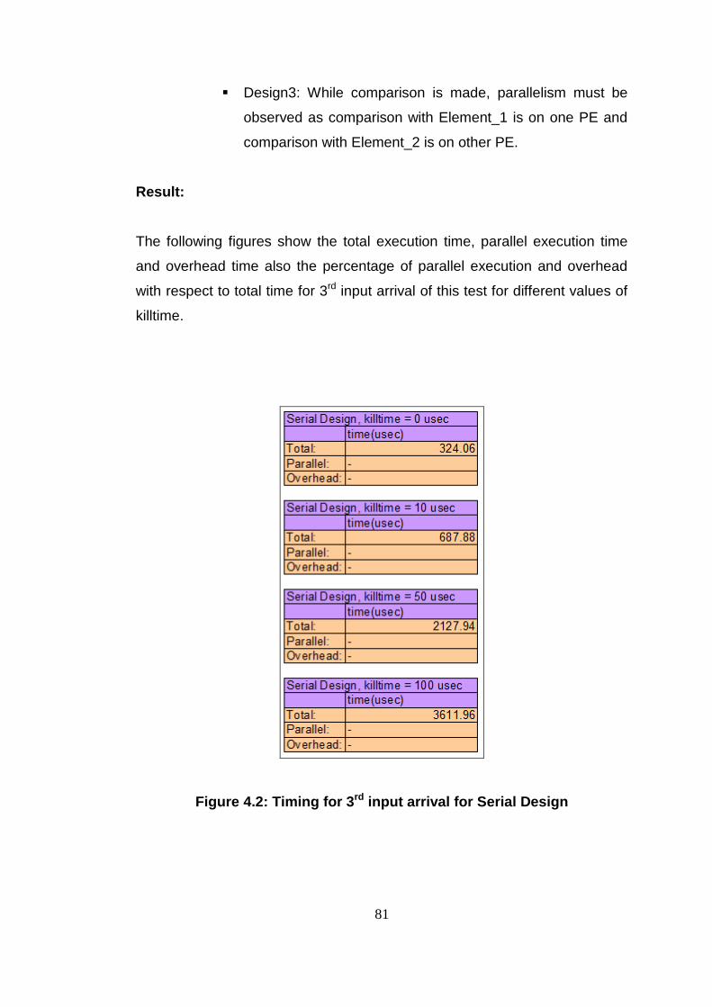
81
Design3: While comparison is made, parallelism must be
observed as comparison with Element_1 is on one PE and
comparison with Element_2 is on other PE.
Result:
The following figures show the total execution time, parallel execution time
and overhead time also the percentage of parallel execution and overhead
with respect to total time for 3rd input arrival of this test for different values of
killtime.
Figure 4.2: Timing for 3rd input arrival for Serial Design

82
Figure 4.3: Timing for 3rd input arrival for Parallel Design 1

83
Figure 4.4: Timing for 3rd input arrival for Parallel Design 2

84
Figure 4.5: Timing for 3rd input arrival for Parallel Design 3
This test is made with 3 elements and 3 input arrivals. Also the
measurements are obtained for the 3rd input arrival which contains three
elements when the current list has two elements. Thus these measurements
do not cover all cases but they show the parallel execution of the specified
case. Test Case 3 can give more information about the parallel executions
for different number of inputs.
85
4.3.2 Test Case 2: Consistency Test
Goal of test:
The main goal of this test is to determine correctness of the source codes
and consistency between serial and parallel software runtime behaviors.
Performance metrics such as Functional correctness and Deterministic
behavior are determined by this test.
Testing Method:
First Step:
o PC is connected to the board serially and connection is
established by putty program. Also putty properties are set as it
writes the all output screen to a log file
o First 50 elements of the input file are used as input of this test
case.
o Source codes of 4 software are compiled PRINT_LIST is
defined and EXTRA_EVENTS, DEBUG1, DEBUG2,
WRITE_TIME are undefined.
o Killtime is set as 10 usec.
o Input elements are sent to the software by one-by-one mode of
auxiliary testing program.
Second Step:
o PC is connected to the board serially and connection is
established by putty program. Also putty properties are set as it
writes the all output screen to a log file.
o First 50 elements of the input file are used as input of this test
case.
o Source codes of 4 software are compiled all EXTRA_EVENTS,
DEBUG1, DEBUG2, WRITE_TIME, PRINT_LIST are
undefined.

86
o Killtime is set as 10 usec.
o Input elements are sent to the software by incremental mode of
auxiliary testing program.
o At the end current list is printed.
Evaluation Method:
For both two steps, by using UltraEdit comparison tool tested parallel
software output log file is compared with the serial software output log
file.
Expectations:
For both steps of the test output files obtained by running software developed
with serial design and three parallel designs must be same.
First step verifies that the parallel and serial software produce the same
output for same input elements. But since input elements are sent one by
one mode, Design 2 does not execute as parallel for the first step. Therefore
second is made to observe the result while parallel execution is made. For
this step all software can run as parallel. Also since elements in list are sent
more times updating of parameters and changes in the value history list can
be verified.
Result:
Serial program log file and parallel programs log files are compared one by
one via UltraEdit comparison tool and its seen that all file are same as
expected.
4.3.3 Test Case 3: Computation Time Test
Goal of test:

87
The main goal of this test case is to measure the A-B timing (time between
two points in execution) for serial and parallel software and compare them. In
this test the computation time ratio between the software are considered
instead of the time value.
Testing Method:
PC is connected to the board serially and connection is established by
putty program. Also putty properties are set as it writes the all output
screen to a log file
All 250 elements of the input file are used as input of this test case.
Source codes of 4 software are compiled WRITE_TIME is defined and
EXTRA_EVENTS, DEBUG1, DEBUG2, PRINT_LIST are undefined.
Input elements are sent to the software by incremental mode of
auxiliary testing program.
This test case is repeated for four times for each software as killtime is
set as 0, 10, 50 and 100 usec.
Evaluation Method:
Using the time difference between start and end of the process, which
is written in the output log file, process time – element number graph
is obtained for all software and all run by Microsoft Excel.
Expectations:
Parallel software must run faster than serial i.e. computation time for
parallel software must be smaller with respect to computation time for
the serial software.
For Parallel Design 1 computation time is expected as nearly 2/3rd of
the serial computation time because two of three update decision or
updating process is made as parallel. Also Parallel Design 1 is
meaningful while update decision and updating for one parameter of a
ListElement is time consuming. Thus Parallel Design 1 must become

88
better as killltime increases.
Parallel Design 2 is better while list size is small. Because as list size
increases update decision process become longer with respect to the
updating process. Thus load balance become worse. Since in this test
list size increase with time, parallelism become worse.
In Parallel Design 3 update decision process time is expected as
nearly half of the serial design. Since in this test list size increase with
time update decision process last longer with respect to the updating
process and it becomes big part of overall computation time. Thus as
time increases, computation time for Parallel Design 3 can becomes
nearly half of the serial design.
Result:
The following two graphs show the computation times for each input arrivals
specified in test method when there is no killtime.

89
Without Killtime
0
500000
1000000
1500000
2000000
2500000
3000000
3500000
0 50 100 150 200 250
Arrival
Co
mp
uta
tio
n T
ime (
usec)
Serial
Design 1
Design 2
Design 3
Figure 4.6: Arrival - computation time graph for 1 to 250 elements of input file for all design when there is no kill time
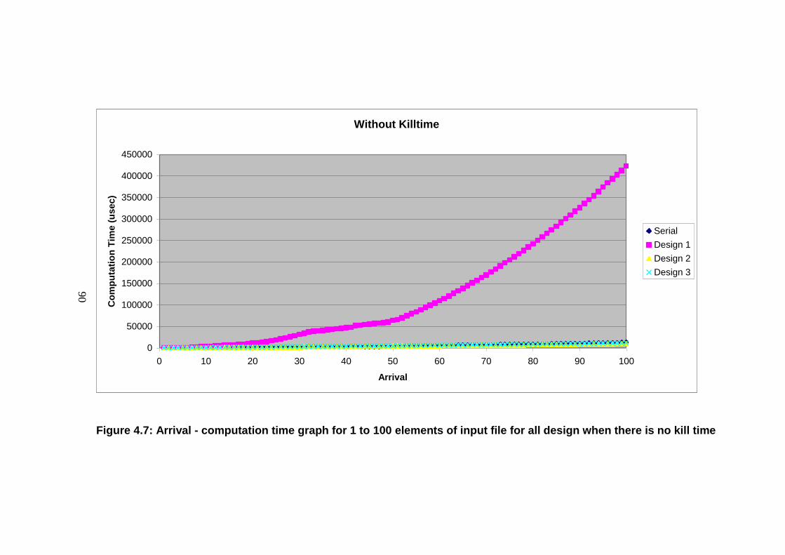
90
Without Killtime
0
50000
100000
150000
200000
250000
300000
350000
400000
450000
0 10 20 30 40 50 60 70 80 90 100
Arrival
Co
mp
uta
tio
n T
ime (
usec)
Serial
Design 1
Design 2
Design 3
Figure 4.7: Arrival - computation time graph for 1 to 100 elements of input file for all design when there is no kill time

91
When there is no killtime on parameter value comparison and update parts
on the source code, computation time for Parallel Design 1 is catastrophic
because the parallelism of Design 1 is on the these parts.
To better view of the graph source data of the Parallel Design 1 is excluded
and the following two graphs are obtained. They show the computation times
for each input arrivals specified in test method for all designs except Parallel
Design 1 when there is no killtime.

92
Without Killtime
0
10000
20000
30000
40000
50000
60000
70000
80000
0 50 100 150 200 250
Arrival
Co
mp
uta
tio
n T
ime (
usec)
Serial
Design 2
Design 3
Figure 4.8: Arrival - computation time graph for 1 to 250 elements of input file for all design except Design 1 when
there is no kill time
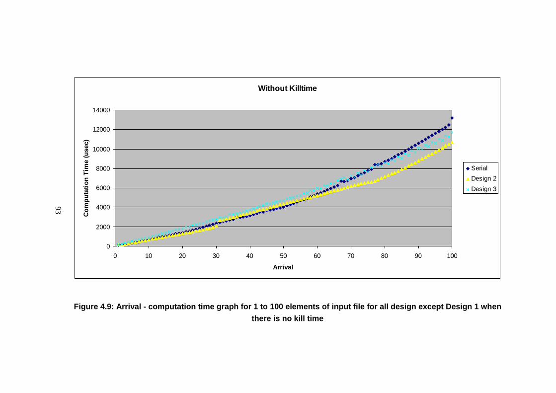
93
Without Killtime
0
2000
4000
6000
8000
10000
12000
14000
0 10 20 30 40 50 60 70 80 90 100
Arrival
Co
mp
uta
tio
n T
ime (
usec)
Serial
Design 2
Design 3
Figure 4.9: Arrival - computation time graph for 1 to 100 elements of input file for all design except Design 1 when
there is no kill time

94
When number of elements in the current list is small, parallel designs are not
faster than serial because of the overheads due to parallel program.
In time, Parallel Design 2 becomes the best in an interval but later when
update decision algorithm computation time becomes larger than the update
algorithm’s as number of elements in the list increases then speed up for
Parallel Design 2 does not increase any more.
Design 3 becomes the best in time as number of elements in the list
increases. The computation time for this design nearly the half as expected.
The following two graphs show the computation times for each input arrivals
specified in test method when killtime is set to 10 usec.
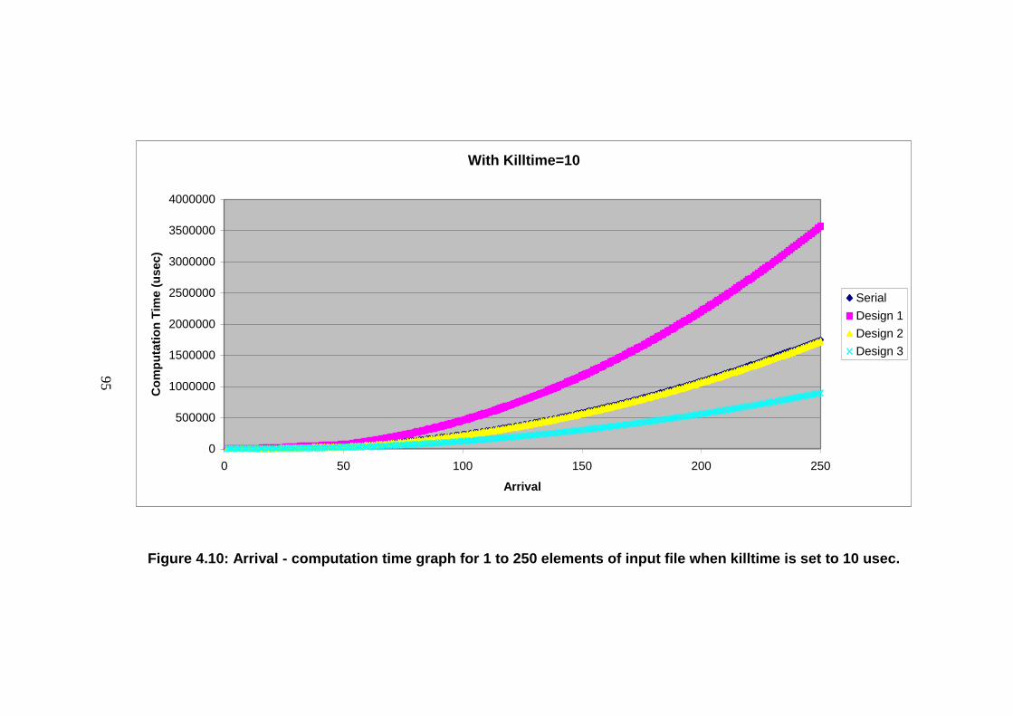
95
With Killtime=10
0
500000
1000000
1500000
2000000
2500000
3000000
3500000
4000000
0 50 100 150 200 250
Arrival
Co
mp
uta
tio
n T
ime (
usec)
Serial
Design 1
Design 2
Design 3
Figure 4.10: Arrival - computation time graph for 1 to 250 elements of input file when killtime is set to 10 usec.
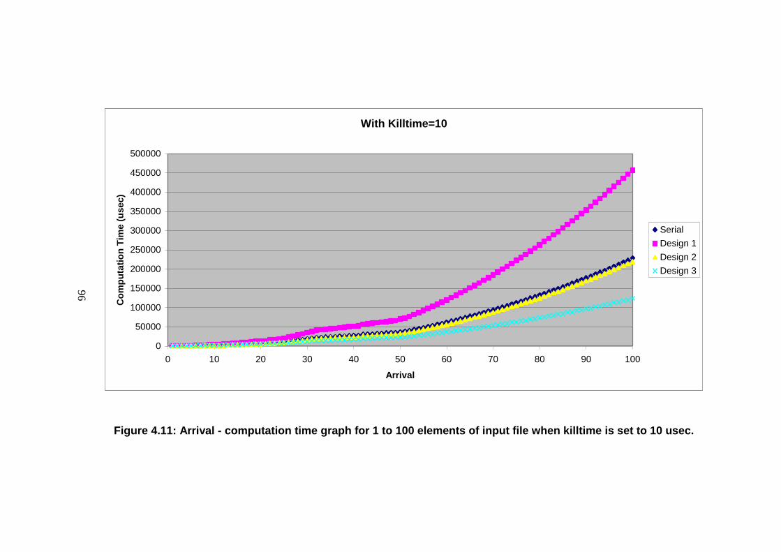
96
With Killtime=10
0
50000
100000
150000
200000
250000
300000
350000
400000
450000
500000
0 10 20 30 40 50 60 70 80 90 100
Arrival
Co
mp
uta
tio
n T
ime (
usec)
Serial
Design 1
Design 2
Design 3
Figure 4.11: Arrival - computation time graph for 1 to 100 elements of input file when killtime is set to 10 usec.

97
When killtime is set to 10 usec behaviors of serial design, Parallel Design 2
and Parallel Design 3 do not changed. But Parallel Design 1 becomes better
since the time difference between the computation time and overhead
become closer.

98
With Killtime=50usec
0
1000000
2000000
3000000
4000000
5000000
6000000
7000000
8000000
9000000
0 50 100 150 200 250
Arrival
Co
mp
uta
tio
n T
ime (
usec)
Serial
Design 1
Design 2
Design 3
Figure 4.12: Arrival - computation time graph for 1 to 250 elements of input file when killtime is set to 50 usec.

99
With Killtime=50usec
0
200000
400000
600000
800000
1000000
1200000
0 10 20 30 40 50 60 70 80 90 100
Arrival
Co
mp
uta
tio
n T
ime (
usec)
Serial
Design 1
Design 2
Design 3
Figure 4.13: Arrival - computation time graph for 1 to 100 elements of input file when killtime is set to 50 usec.

100
When killtime is set to 50 usec, Parallel Design 1 becomes better and
meaningful because the computation time for it is less than the computation
time for serial design.
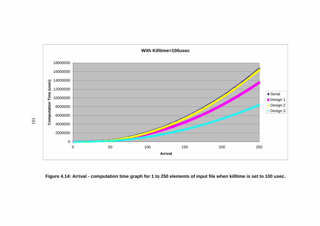
101
With Killtime=100usec
0
2000000
4000000
6000000
8000000
10000000
12000000
14000000
16000000
18000000
0 50 100 150 200 250
Arrival
Co
mp
uta
tio
n T
ime (
usec)
Serial
Design 1
Design 2
Design 3
Figure 4.14: Arrival - computation time graph for 1 to 250 elements of input file when killtime is set to 100 usec.
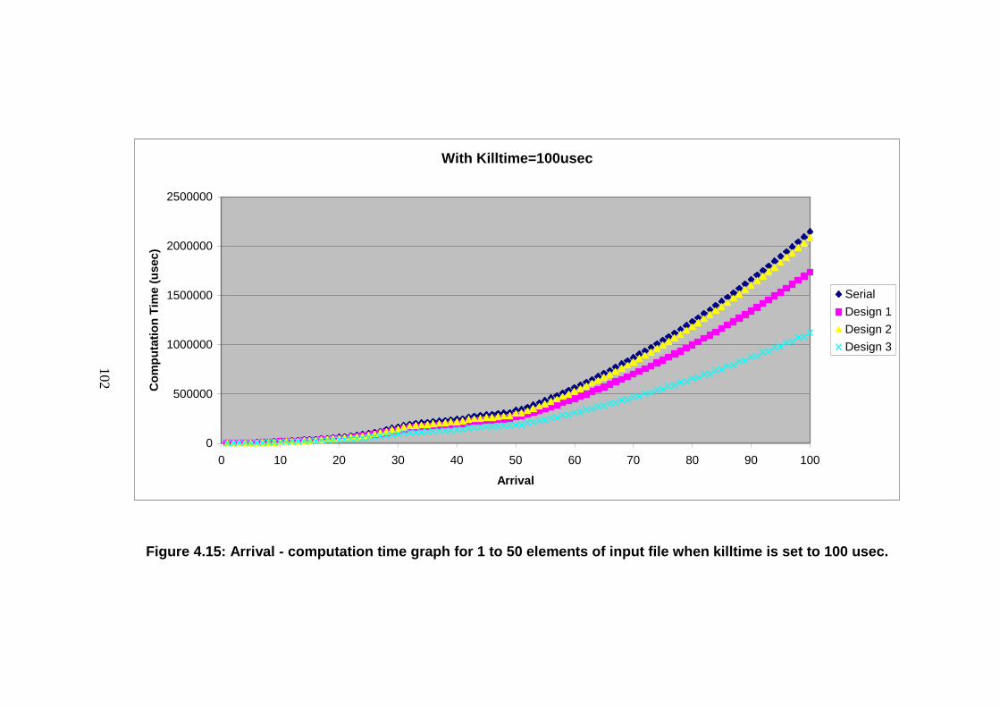
102
With Killtime=100usec
0
500000
1000000
1500000
2000000
2500000
0 10 20 30 40 50 60 70 80 90 100
Arrival
Co
mp
uta
tio
n T
ime (
usec)
Serial
Design 1
Design 2
Design 3
Figure 4.15: Arrival - computation time graph for 1 to 50 elements of input file when killtime is set to 100 usec.

103
When killtime is set to 100 usec Parallel Design 3 becomes more meaningful
to exploit the concurrency.
Following comments can be deduced from the result of this test:
The best design is Design 3 considering the execution speed.
Design 1 is meaningful when the parameter value comparison and
update part of the program is time consuming.
Speed up for the Design 2 stops when computation time for the
update decision algorithm becomes longer than the computation time
for update algorithm.
4.3.4 Test Case 4: Time Constraint Test
Goal of test:
The main goal of this test is to measure the performance metrics such as A-B
timing timeliness (the ability to meet all deadlines) and deterministic behavior.
Testing Method:
PC is connected to the board serially and connection is established by
putty program. Also putty properties are set as it writes the all output
screen to a log file
First 50 elements of the input file are used as input of this test case.
Source codes of 4 software are compiled WRITE_TIME is defined and
EXTRA_EVENTS, DEBUG1, DEBUG2, PRINT_LIST are undefined.
Killtime is set as 50 usec.
Input elements are sent to the software by selecting all and continuous
mode of auxiliary testing program.
After sending 51 times test is stopped.
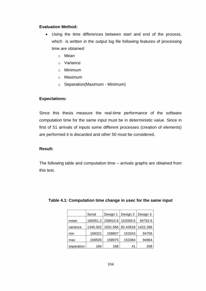
104
Evaluation Method:
Using the time differences between start and end of the process,
which is written in the output log file following features of processing
time are obtained:
o Mean
o Variance
o Minimum
o Maximum
o Separation(Maximum - Minimum)
Expectations:
Since this thesis measure the real-time performance of the software
computation time for the same input must be in deterministic value. Since in
first of 51 arrivals of inputs some different processes (creation of elements)
are performed it is discarded and other 50 must be considered.
Result:
The following table and computation time – arrivals graphs are obtained from
this test.
Table 4.1: Computation time change in usec for the same input
Serial Design 1 Design 2 Design 3
mean 169351.2 158910.8 153358.6 94792.6
variance 1345.002 1931.566 82.43918 1422.286
min 169321 158807 153343 94756
max 169505 158975 153384 94964
separation 184 168 41 208

105
There is no big difference among the serial and parallel designs considering
the change of the response time for each arrival of the same input. Thus all
designs can be acceptable regarding the real time constraints.

106
CHAPTER 5
DISCUSSION AND CONCLUSION
Faster computers are being required to solve today’s big and complex
problems. To meet this, chip developers have produced the multicore
processors. Also software developers must develop their skills to adapt this
new hardware and to take the advantages of it. Parallel programming has
been become mandatory. Parallel programming patterns help software
developers for better parallel software.
In this thesis, to determine the effects of parallel programming patterns on
real time performance, one serial and three parallel software designs are
implemented to solve a list management algorithm. Serial software is
designed by the traditional methods without any parallel programming
pattern. In the first parallel design, parallelism is on the tasks which carry out
the same tasks three times in one pass of the algorithm. In the second
parallel design, parallelism is obtained as pipelining the two sequential tasks
and synchronizing them by events. In the third parallel design, parallelism is
on the iterations of a loop.
All parallel designs exhibit better performance in comparison to the serial
design. But performance gains and other software quality factors are different
among them.
The first design, which is based on loop parallelism on parameter
comparison, is clear to understand but it is not scalable with the processor

107
number because it has only three parallel tasks. Also the performance
improvement for this design depends directly on the work load of the parallel
task. To obtain better performance with such a design load of the tasks must
be big enough else performance become worse than the serial design
because of the overheads due to parallelism such as tasks switch, task
communication etc.
The second design, that is pipeline structure, is the most complex one to
understand and it is not scalable with the processor number because it has
only two parallel tasks. Also if the work load of these tasks differs,
performance improvement decreasing. To obtain better performance with
such a design load of the tasks must be comparable.
The third design, which is based on loop parallelism on element comparison,
is the most clear to understand because it is the closest one to the serial
design. Also it is as scalable design as loop iterations can be diminished in to
tasks where tasks have enough work. Since tasks are the iterations of a loop
all tasks have nearly same work load. If this kind of parallelism can be
obtained for an algorithm it must be the first choice.
In this thesis, applicability of parallel programming patterns to the real time
software is shown. Also it can be proved that parallel programming effort is
worthwhile to obtain better performance from the multicore processor for real
time software by implementing a real time algorithm that is already used in
practice. Improvement on real time performance, reduction in power
consumption and deterministic behavior encourage the real time software
developers to use multicore processors and parallel programming patterns.
VxWorks 6.6 with SMP is used in this thesis as real time operating system.
WindRiver VxWorks product is one of the most reliable and well supported
real time operating system. Some important issues for parallel programming
such as load balancing, task communication mechanism etc. are provided by
108
the operating system features.
Moreover in this thesis the pattern language in [1] is tried on an algorithm
with real time constraints. Patterns in this pattern language are high level
patterns which address the analysis the problem and software design. They
also offer some implementation methods. This language is mostly useful to
learn parallel thinking about a problem while analyzing it and also to form the
general architecture of the software which implements the problem as
parallel.
The main shortcoming of the present study is also related to its strength:
namely, the fact that it is based on an experimental study. As such, while it is
repeatable for experiments that involve highly similar characteristics, there is
no claim to generalizability of results. That is, how design patterns affect
performance in general, is not a conclusion that is or that could be derived in
this study.
In this thesis, only one hardware platform with dualcore processor is used
and VxWorks 6.6 with SMP operating system is run on it. To derive more
conclusive evaluations, the test program needs to be tried with different
hardware and operating systems. This is the first suggestion for immediate
future work.
Although list management algorithm is implemented with three different
ways, another algorithm can be implemented in future works. This would
naturally enrich the evaluations in terms of generalizability of results.
Moreover, parallel designs in this thesis are based on the pattern language in
[1]. Other parallel programming patterns and pattern languages or parallel
programming environments with parallel programming languages, compilers,
frameworks can be tried and compared in future studies.

109
REFERENCES
[1] Mattson, T. G., Sanders, B. A., and Massingill, B. L., “Patterns for Parallel
Programming”, Addison-Wesley, 2004
[2] Geer, D., “Industry Trends: Chip Makers Turn to Multicore Processors”,
IEEE Computer, vol. 38, no. 5, pp. 11-13, May,
[3] AMD White Paper, “Multi-Core Processors - The next evolution in
computing”, 2005
[4] Flynn, M. J., “Some computer organizations and their effectiveness”, IEEE
Transactions on Computers, C-21(9), 1972
[5] “Wikipedia – Flynn Taxonomy”,
http://en.wikipedia.org/wiki/Flynn%27s_taxonomy, last visited on June 2010
[6] Wind River Systems, Inc., “VxWorks 6.6 SMP Product Note”, 2007
[7] Siddha, S., “Multi-core and Linux* Kernel”, Intel Open Source Technology
Center, March 2007
[8] Geer, D., “For Programmers, Multicore Chips Mean Multiple Challenges”
IEEE Computer, vol. 40, no. 9, pp. 17-19, August 2007
[9] Quinnell, R. A., “Multicore partitioning is a threads and comms problem”,
EE Times, October 20, 2008
[10] Kanaracus, C., “Multicore Boom Needs New Developer Skills”, IDG
110
News Service, Friday, March 21, 2008
[11] Reinders, J., “Rules for Parallel Programming for Multicore”, Dr. Dobb's
Journal, 32, 10; ProQuest Computing pg. 10, October 2007
[12] Asanovic, K., Bodik, R., Demmel, J., Keaveny, T., Keutzer, K.,
Kubiatowicz, J. D., Lee, E. A., Morgan, N., Necula, G., Patterson, D. A., Sen,
K., Wawrzynek, J., Wessel, D. and Yelick, K. A., “The Parallel Computing
Laboratory at U.C. Berkeley: A Research Agenda Based on the Berkeley
View”, Electrical Engineering and Computer Sciences at University of
California at Berkeley, March 21, 2008
[13] Aiken, A., Dally, B., Fedkiw, R., Hanrahan, P., Hennessy, J., Horowitz,
M., Koltun, V., Kozyrakis, C., Olukotun, K., Rosenblum, M., and Thrun, S.,
“The Stanford Pervasive Parallelism Lab”, August 2008
[14] Adve, S. V., Adve, V. S., Agha, G., Frank, M. I., Garzarán, M. J., Hart, J.
C., Hwu, W. W., Johnson, R. E., Kale, L. V., Kumar, R., Marinov, D.,
Nahrstedt, K., Padua, D., Parthasarathy, M., Patel, S. J., Rosu, G., Roth, D.,
Snir, M., Torrellas, J., Zilles, C. “Parallel Computing Research at Illinois The
UPCRC Agenda”, University of Illinois at Urbana-Champaign, November
2008
[15] Snir, M., et.al., “Ubiquitous Parallel Computing from Berkeley, Illinois and
Stanford”, IEEE Micro, 2010
[16] Buschmann, F., Henney, K., Schmidt, D., “Pattern-Oriented Software
Architecture: A Pattern Language for Distributed Computing”, Wiley, India,
2007
[17] Asanovic, K., et.al., “A view of the parallel computing landscape”, Comm.
ACM, 52:10, October 2009

111
[18] Fluet, M., et.al., “Manticore: a heterogeneous parallel language”, Annual
Symposium on Principles of Programming Languages; Proceedings of the
2007 workshop on Declarative aspects of multicore programming, Nice,
France, pp.37 – 44, 2007
[19] Christopher, A., et al., “A Pattern Language Towns, Buildings,
Construction”, Vol.2, New York: Oxford University Press, 1977
[20] “A Pattern Language For Parallel Programming Ver 2.0”,
http://parlab.eecs.berkeley.edu/wiki/patterns/patterns, last visited on June
2010
[21] Douglass, B. P., “Real-Time Design Patterns: Robust Architecture for
Real- Time Systems”, Addision-Wesley, 2002
[22] Mattson, T., “Teaching people how to think parallel”, Principal Engineer
Application Research Laboratory Intel Corp, 2009
[23] Johnson, R., “Parallel Programming Patterns”, The Universal Parallel
Computing Research Center, Illinois, September 19, 2008
[24] Mattson, T., “Our Pattern Language (OPL)”, February 13, 2009
[25] Hillary, N., “Measuring Performance for Real-Time Systems, Rev.0”,
Freescale Semiconductor , November 2005
[26] Halang, W. A., “Measuring the Performance of Real-Time Systems”,
2000
[27] Zalewski, J., “From Software Sensitivity to Software Dynamics:
Performance Metrics for Real-Time Software Architectures”, July 2005

112
[28] Hwang, K., Xu, Z., “Scalable parallel computers for real-time signal
processing”, Hong Kong Univ., July 1996
[29] Wind River Systems, Inc., “Wind River Workbench USER’S GUIDE 3.0”,
2007
[30] Wind River Systems, Inc., “VxWorks KERNEL PROGRAMMER'S GUIDE
6.6”, 2007
[31] Wind River Systems, Inc., “2007Wind River System Viewer USER'S
GUIDE 3.0”, 2007
[32] Wind River Systems, Inc., “Wind River VxWorks Simulator USER'S
GUIDE 6.6”, 2007
[33] Wind River Systems, Inc., “Wind River Workbench Function Tracer
USER'S GUIDE 3.0”, 2007
[34] Wind River Systems, Inc., “Wind River SBC8641D Engineering
Reference Guide”, 2007
[35] Freescale MPC8641D Product Summary Page,
http://www.freescale.com/webapp/sps/site/prod_summary.jsp?code=MPC86
41D, last visited on June 2010

113
APPENDIX-A
Table of Elements in Input File
Table A.1: Test Input Set
No major Xmin Xmax Ymin Ymax Zmin Zmax Decision
1 0 1001 1001 101 101 11 11 new element with ID=1
2 0 1001 1001 101 101 11 11 update element with ID=1
3 0 1000 1002 101 101 11 11 update element with ID=1
4 0 1001 1001 100 102 11 11 update element with ID=1
5 0 1001 1001 101 101 10 12 update element with ID=1
6 0 1501 1501 101 101 11 11 new element with ID=2
7 0 1501 1501 151 151 11 11 new element with ID=3
8 0 1501 1501 151 151 15 15 new element with ID=4
9 0 1500 1502 151 151 15 15 update element with ID=4
10 0 1496 1506 151 151 15 15 update element with ID=4
11 0 1504 1514 151 151 15 15 new element with ID=5
12 0 1489 1499 151 151 15 15 update element with ID=4
13 0 1601 1601 161 161 16 16 new element with ID=6
14 0 1601 1601 160 162 16 16 update element with ID=6
15 0 1601 1601 156 166 16 16 update element with ID=6
16 0 1601 1601 164 174 16 16 new element with ID=7
17 0 1601 1601 149 159 16 16 update element with ID=6
18 0 1801 1801 181 181 18 18 new element with ID=8
19 0 1801 1801 181 181 17 19 update element with ID=9
20 0 1801 1801 181 181 13 23 update element with ID=9
21 0 1801 1801 181 181 24 29 new element with ID=10
22 0 1801 1801 181 181 10 15 update element with ID=9
23 50 1001 1001 101 101 11 11 new element with ID=11
24 50 1501 1501 101 101 11 11 new element with ID=12
25 50 1501 1501 151 151 11 11 new element with ID=13
26 50 1501 1501 151 151 15 15 new element with ID=14
27 50 1504 1514 151 151 15 15 new element with ID=15
28 50 1601 1601 161 161 16 16 new element with ID=16
29 50 1601 1601 164 174 16 16 new element with ID=17
30 50 1801 1801 181 181 18 18 new element with ID=18
31 50 1801 1801 181 181 24 29 new element with ID=19
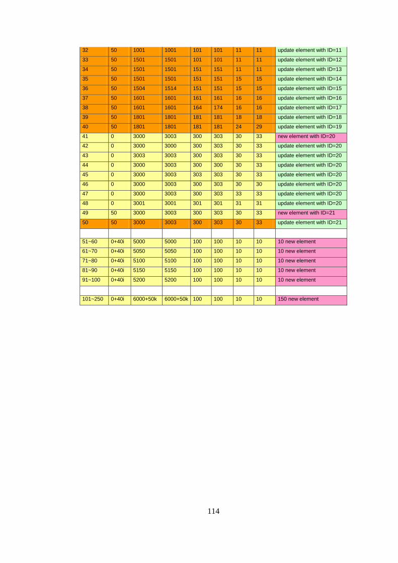
114
32 50 1001 1001 101 101 11 11 update element with ID=11
33 50 1501 1501 101 101 11 11 update element with ID=12
34 50 1501 1501 151 151 11 11 update element with ID=13
35 50 1501 1501 151 151 15 15 update element with ID=14
36 50 1504 1514 151 151 15 15 update element with ID=15
37 50 1601 1601 161 161 16 16 update element with ID=16
38 50 1601 1601 164 174 16 16 update element with ID=17
39 50 1801 1801 181 181 18 18 update element with ID=18
40 50 1801 1801 181 181 24 29 update element with ID=19
41 0 3000 3003 300 303 30 33 new element with ID=20
42 0 3000 3000 300 303 30 33 update element with ID=20
43 0 3003 3003 300 303 30 33 update element with ID=20
44 0 3000 3003 300 300 30 33 update element with ID=20
45 0 3000 3003 303 303 30 33 update element with ID=20
46 0 3000 3003 300 303 30 30 update element with ID=20
47 0 3000 3003 300 303 33 33 update element with ID=20
48 0 3001 3001 301 301 31 31 update element with ID=20
49 50 3000 3003 300 303 30 33 new element with ID=21
50 50 3000 3003 300 303 30 33 update element with ID=21
51~60 0+40i 5000 5000 100 100 10 10 10 new element
61~70 0+40i 5050 5050 100 100 10 10 10 new element
71~80 0+40i 5100 5100 100 100 10 10 10 new element
81~90 0+40i 5150 5150 100 100 10 10 10 new element
91~100 0+40i 5200 5200 100 100 10 10 10 new element
101~250 0+40i 6000+50k 6000+50k 100 100 10 10 150 new element