effects of angle-of-attack on lift and thrust€¦ · effects of angle-of-attack on lift and thrust...
TRANSCRIPT
EFFECTS OF ANGLE-OF-ATTACK ON LIFT AND THRUST
EXPERIMENTAL STUDY VIA TEST APPARATUS WITH PASSIVE WING ROTATION
Yutong Wang
Department of Engineering, Australian National University Canberra, 0200, Australia [email protected]
Shankar Kalyanasundaram
Department of Engineering, Australian National University Canberra, 0200, Australia [email protected]
John Young
School of Aerospace, Civil and Mechanical Engineering The University of New South Wales at the Australian Defence Force Academy
Canberra, 2600, Australia [email protected] Abstract: - This paper focuses on the effect of mean angle-of-attack (AOA) on aerodynamic forces of flapping wings. The study was conducted with the aid of a test bench, which provided an active flapping motion in a vertical stroke plane and meanwhile a passive rotating motion about the longitudinal axis of the tested wing having the planform of a dragonfly’s hindwing. AOA effect was studied together with the wing stiffness effect using Taguchi’s DOE method in order to extract the major effects with minimum expenditure both in labor and time. The experimental results indicated that during downstroke, the lift decreased with the decreasing of the overall AOA monotonically, but thrust increased. However, during upstroke, the relationship between the effects of mean AOA and aerodynamic forces were not monotonic: larger and smaller AOAs were beneficial to the lift; smaller AOA was detrimental to the thrust; and the effect of larger AOA on thrust was close to the one caused by medium AOA.
Key-Words: - Angle of attack, Passive rotation, Flapping wing, Effect on lift and thrust
1. Introduction
Angle-of-attack ( AOA ) plays an important role in flight for all types of flyers, such as insects, bats, and birds found in nature; and aeroplanes, helicopters and ornithopters made by human. In the case of a fixed wing, geometrical AOA is defined as the angle between the
chord direction (from tail to tip) and wing forward velocity, as shown in Figure 1; the effective angle of attack is the angle between the chord direction and the direction of the effective velocity formed by the wing forward velocity and the wing velocity relative to the downwash.
Proceedings of the 6th WSEAS International Conference on FLUID MECHANICS (FLUIDS'09)
ISSN: 1790-5095 126 ISBN: 978-960-474-40-6
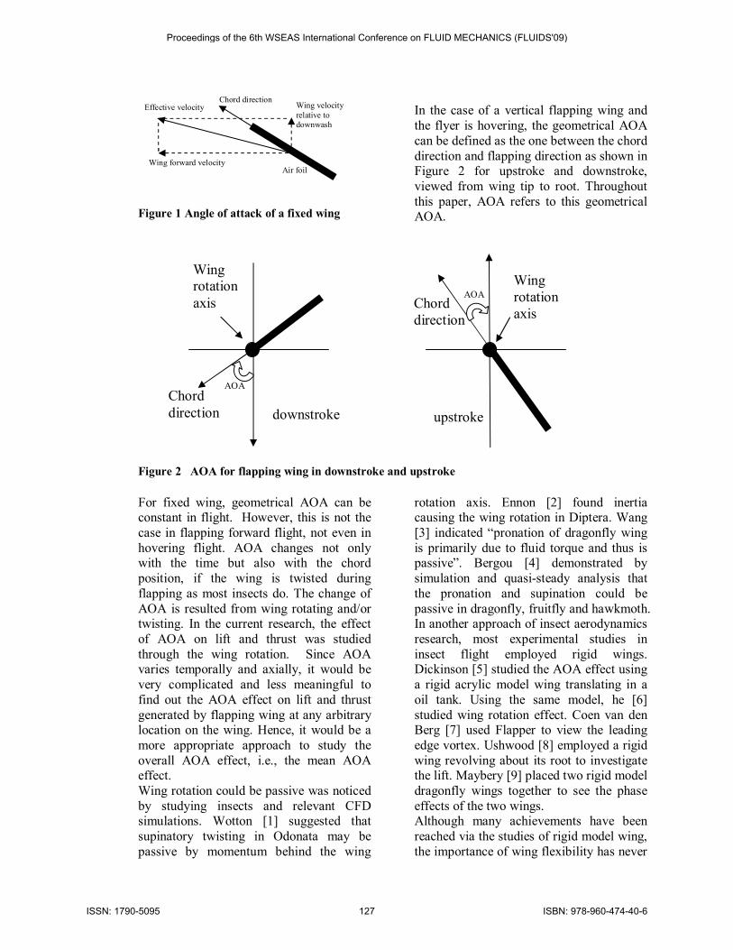
Figure 1 Angle of attack of a fixed wing
In the case of a vertical flapping wing and the flyer is hovering, the geometrical AOA can be defined as the one between the chord direction and flapping direction as shown in Figure 2 for upstroke and downstroke, viewed from wing tip to root. Throughout this paper, AOA refers to this geometrical AOA.
Figure 2 AOA for flapping wing in downstroke and upstroke For fixed wing, geometrical AOA can be constant in flight. However, this is not the case in flapping forward flight, not even in hovering flight. AOA changes not only with the time but also with the chord position, if the wing is twisted during flapping as most insects do. The change of AOA is resulted from wing rotating and/or twisting. In the current research, the effect of AOA on lift and thrust was studied through the wing rotation. Since AOA varies temporally and axially, it would be very complicated and less meaningful to find out the AOA effect on lift and thrust generated by flapping wing at any arbitrary location on the wing. Hence, it would be a more appropriate approach to study the overall AOA effect, i.e., the mean AOA effect. Wing rotation could be passive was noticed by studying insects and relevant CFD simulations. Wotton [1] suggested that supinatory twisting in Odonata may be passive by momentum behind the wing
rotation axis. Ennon [2] found inertia causing the wing rotation in Diptera. Wang [3] indicated “pronation of dragonfly wing is primarily due to fluid torque and thus is passive”. Bergou [4] demonstrated by simulation and quasi-steady analysis that the pronation and supination could be passive in dragonfly, fruitfly and hawkmoth. In another approach of insect aerodynamics research, most experimental studies in insect flight employed rigid wings. Dickinson [5] studied the AOA effect using a rigid acrylic model wing translating in a oil tank. Using the same model, he [6] studied wing rotation effect. Coen van den Berg [7] used Flapper to view the leading edge vortex. Ushwood [8] employed a rigid wing revolving about its root to investigate the lift. Maybery [9] placed two rigid model dragonfly wings together to see the phase effects of the two wings. Although many achievements have been reached via the studies of rigid model wing, the importance of wing flexibility has never
Wing rotation axis
Chord direction downstroke
Wing rotation axis
Chord direction
upstroke
AOA
AOA
Chord direction
Wing forward velocity
Air foil
Wing velocity relative to downwash
Effective velocity
Proceedings of the 6th WSEAS International Conference on FLUID MECHANICS (FLUIDS'09)
ISSN: 1790-5095 127 ISBN: 978-960-474-40-6
been neglected (Ennons [10], Combes[11], Newmann[12]). In fact, all the natural flyers use flexible wings to fly. The wing passive rotation and deformability are the two now-trivial features in insect flight. Very few researches have been done in the effects of above two characteristics on lift and thrust. Experimental data are very sparse and far from complete. Wing rotation and deformability are virtually equivalent to the AOA and stiffness respectively. To seek the insights into the effects of mean AOA on lift and thrust of the flexible wing in its hovering state, the current research was carried out with a test bench which featured an active wing flapping but purely passive wing rotating mechanism. “Purely passive” means it rotates by wing inertial and aerodynamic forces, and the overall wing rotation angle control at the wing root is by passive components (springs) rather than active part (motor). Flexible wings were used in the experiment whose stiffness varied from wing to wing. A DOE method
was applied to minimize the unnecessary labor but extract the major effects. Although the effects of stiffness were studied at the same time, this paper concentrates only on the effects of the mean AOA.
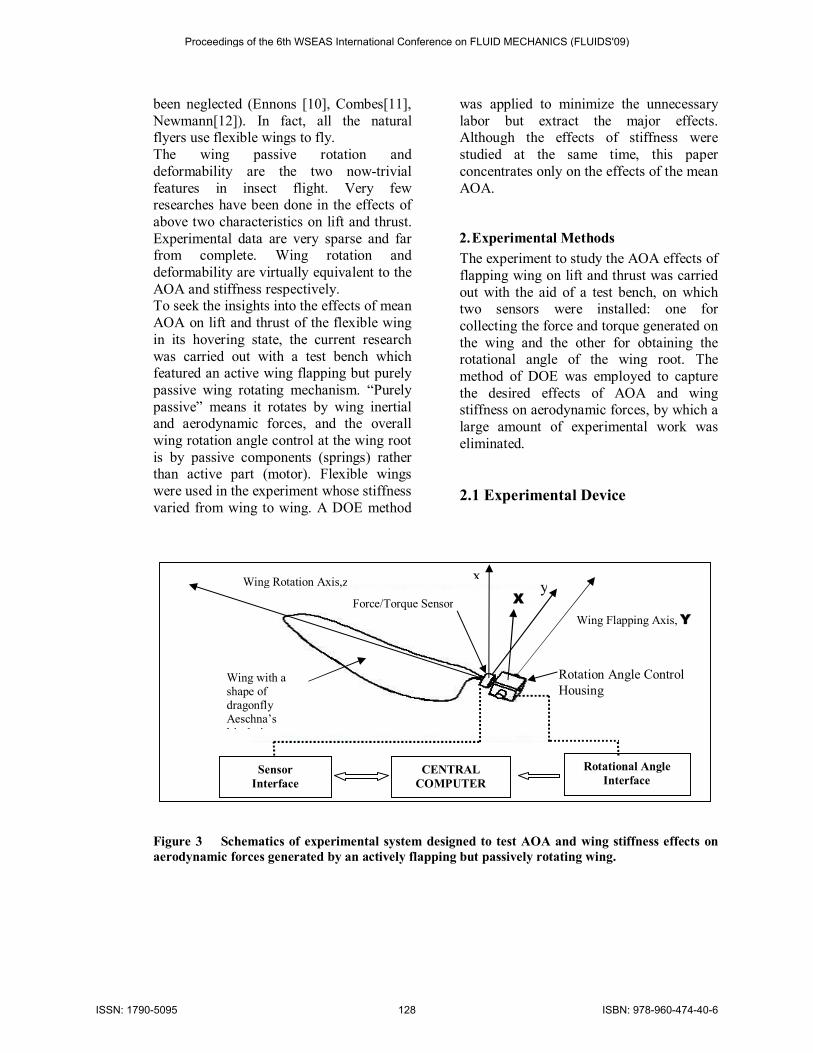
2. Experimental Methods The experiment to study the AOA effects of flapping wing on lift and thrust was carried out with the aid of a test bench, on which two sensors were installed: one for collecting the force and torque generated on the wing and the other for obtaining the rotational angle of the wing root. The method of DOE was employed to capture the desired effects of AOA and wing stiffness on aerodynamic forces, by which a large amount of experimental work was eliminated. 2.1 Experimental Device
Figure 3 Schematics of experimental system designed to test AOA and wing stiffness effects on aerodynamic forces generated by an actively flapping but passively rotating wing.
Wing Rotation Axis,z
Wing Flapping Axis, Y
Force/Torque Sensor
Rotation Angle Control Housing
CENTRAL COMPUTER
Sensor Interface
Rotational Angle Interface
yx
X
Wing with a shape of dragonfly Aeschna’s hindwing
Proceedings of the 6th WSEAS International Conference on FLUID MECHANICS (FLUIDS'09)
ISSN: 1790-5095 128 ISBN: 978-960-474-40-6
The experimental system shown in Figure 3 contains three major subsystems, namely mechanical, electrical and data acquisition system. The major function for electrical system is to drive the wing and control the flapping speed. Data acquisition system (DAS) employs a 6 degree of freedom (6 DOF) force and torque sensor mounted on the wing root to collect the force and torque generated by the wing in xyz-space. DAS also employs a sensor located inside Rotation Angle Control Housing to collect wing’s rotational angle which is necessary for calculating the AOA and converting the force/torque data from sensor reference to
ground reference in the pro-test data processing. In mechanical system, there are two major assemblies, which are the wing flapping mechanism simplified as the wing flapping axis in Figure 3 and 5, and the wing rotating mechanism including wing itself, force/torque sensor and wing rotation angle control assembly inside Rotation Angle Control Housing. Wing flapping mechanism generates an oscillating motion for wing to flap in a vertical stroke plane about wing flapping axis. Wing rotation mechanism makes the wing rotating about the wing rotation axis passively which will be discussed in detail in next section 2.2.
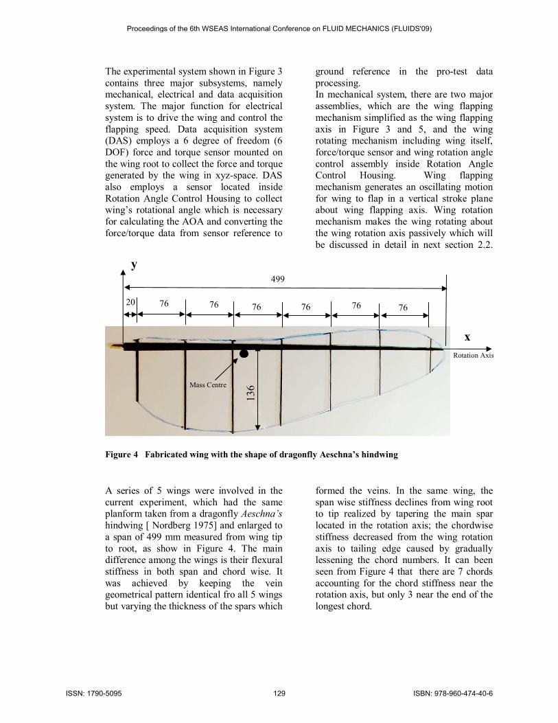
Figure 4 Fabricated wing with the shape of dragonfly Aeschna’s hindwing
A series of 5 wings were involved in the current experiment, which had the same planform taken from a dragonfly Aeschna’s hindwing [ Nordberg 1975] and enlarged to a span of 499 mm measured from wing tip to root, as show in Figure 4. The main difference among the wings is their flexural stiffness in both span and chord wise. It was achieved by keeping the vein geometrical pattern identical fro all 5 wings but varying the thickness of the spars which
formed the veins. In the same wing, the span wise stiffness declines from wing root to tip realized by tapering the main spar located in the rotation axis; the chordwise stiffness decreased from the wing rotation axis to tailing edge caused by gradually lessening the chord numbers. It can been seen from Figure 4 that there are 7 chords accounting for the chord stiffness near the rotation axis, but only 3 near the end of the longest chord.
y 13
6
499
76 76
76
20
x Rotation Axis
76
76
76
Mass Centre
Proceedings of the 6th WSEAS International Conference on FLUID MECHANICS (FLUIDS'09)
ISSN: 1790-5095 129 ISBN: 978-960-474-40-6
2.2. Passive Wing Rotation Mechanism
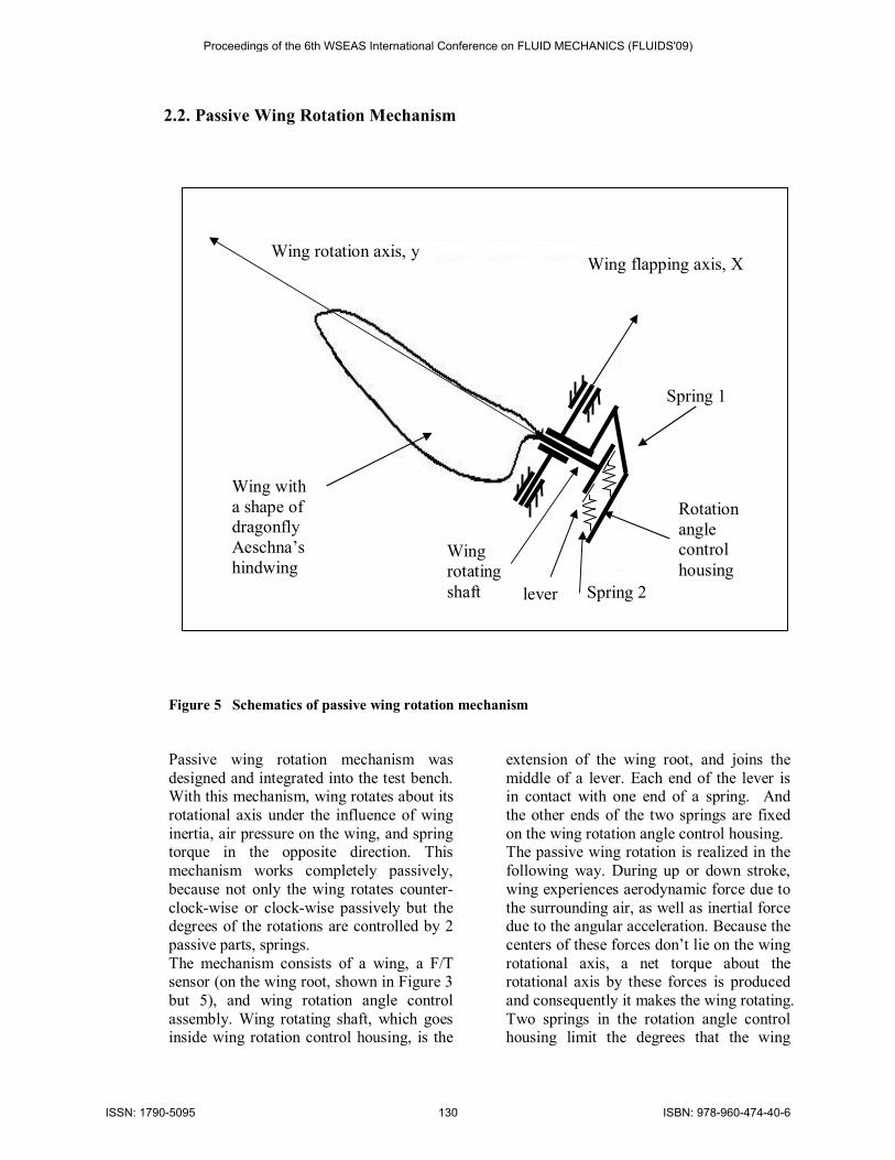
Figure 5 Schematics of passive wing rotation mechanism Passive wing rotation mechanism was designed and integrated into the test bench. With this mechanism, wing rotates about its rotational axis under the influence of wing inertia, air pressure on the wing, and spring torque in the opposite direction. This mechanism works completely passively, because not only the wing rotates counter-clock-wise or clock-wise passively but the degrees of the rotations are controlled by 2 passive parts, springs. The mechanism consists of a wing, a F/T sensor (on the wing root, shown in Figure 3 but 5), and wing rotation angle control assembly. Wing rotating shaft, which goes inside wing rotation control housing, is the
extension of the wing root, and joins the middle of a lever. Each end of the lever is in contact with one end of a spring. And the other ends of the two springs are fixed on the wing rotation angle control housing. The passive wing rotation is realized in the following way. During up or down stroke, wing experiences aerodynamic force due to the surrounding air, as well as inertial force due to the angular acceleration. Because the centers of these forces don’t lie on the wing rotational axis, a net torque about the rotational axis by these forces is produced and consequently it makes the wing rotating. Two springs in the rotation angle control housing limit the degrees that the wing
Spring 1
Rotation angle control housing
Spring 2
Wing flapping axis, X Wing rotation axis, y
Wing with a shape of dragonfly Aeschna’s hindwing
Wing rotating shaft lever
Proceedings of the 6th WSEAS International Conference on FLUID MECHANICS (FLUIDS'09)
ISSN: 1790-5095 130 ISBN: 978-960-474-40-6
could rotate in either direction independently. By changing the stiffness in the spring, the angle of wing rotation shaft
will change accordingly, hence the overall AOA.
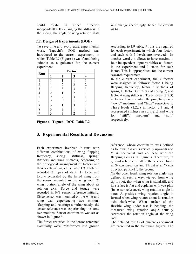
2.2. Design of Experiments (DOE) To save time and avoid extra experimental work, Taguchi’s DOE method was introduced to the current experiment, in which Table L9 (Figure 6) was found being suitable as a guidance for the current experiment.
Factor Run 1 2 3 4
1 1 1 1 1 2 1 2 2 2 3 1 3 3 3 4 2 1 2 3 5 2 2 3 1 6 2 3 1 2 7 3 1 3 2 8 3 2 1 3 9 3 3 2 1
Figure 6 Taguchi' DOE Table L9.
According to L9 table, 9 runs are required for each experiment, in which four factors and each with 3 levels are involved. In another words, it allows to have maximum four independent input variables as factors in the experiment and 3 states for each factor. This is appropriated for the current research requirement. In the current experiment, the 4 factors were assigned as follows: factor 1 being flapping frequency; factor 2 stiffness of spring 1; factor 3 stiffness of spring 2; and factor 4 wing stiffness. Three levels (1,2,3) in factor 1 represented flapping frequency “low”,” medium” and “high” respectively. Three levels (1,2,3) in factor 2,3 and 4 represented stiffness in spring1,2 and wing for “stiff”,” medium” and “soft” respectively.
3. Experimental Results and Discussion
Each experiment involved 9 runs with different combinations of wing flapping frequency, spring1 stiffness, spring2 stiffness and wing stiffness, according to the orthogonal arrangement of factors and their levels in Taguchi’s Table L9. Each run recorded 2 types of data: 1) force and torque generated by the tested wing from the sensor mounted in the wing root; 2) wing rotation angle of the wing about its rotation axis. Force and torque were recorded in F/T sensor reference initially. Since sensor was mounted on the wing and wing was experiencing two motions (flapping and rotating) simultaneously, the sensor reference was experiencing the same two motions. Sensor coordinates was set as shown in Figure 3. The forces recorded in the sensor reference eventually were transformed into ground
reference, whose coordinates was defined as follows: X-axis is vertically upwards and Y is horizontal and collinear with the flapping axis as in Figure 3. Therefore, in ground reference, Lift is the vertical force in X-axis direction and Thrust is in Y-axis direction parallel to the ground. On the other hand, wing rotation angle was defined in such a way, viewed from wing tip to root, that when wing is standstill, and its surface is flat and coplanar with yoz plan (in sensor reference), wing rotation angle is zero; A positive wing rotation angle is formed when wing rotates about its rotation axis clock-wise. When surface of the flexible wing under test is bending, the measured wing rotation angle actually represents the rotation angle at the wing root. The detailed results of current experiment are presented in the following figures. The
Proceedings of the 6th WSEAS International Conference on FLUID MECHANICS (FLUIDS'09)
ISSN: 1790-5095 131 ISBN: 978-960-474-40-6
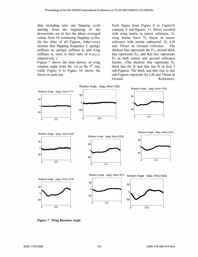
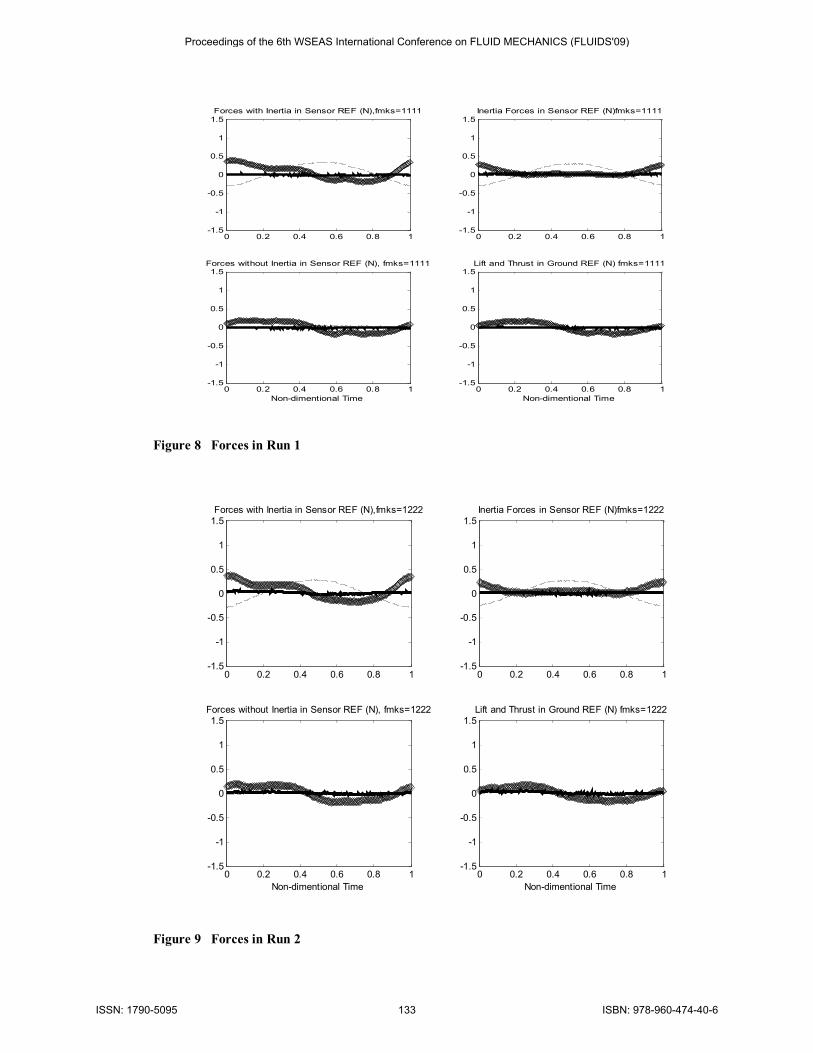
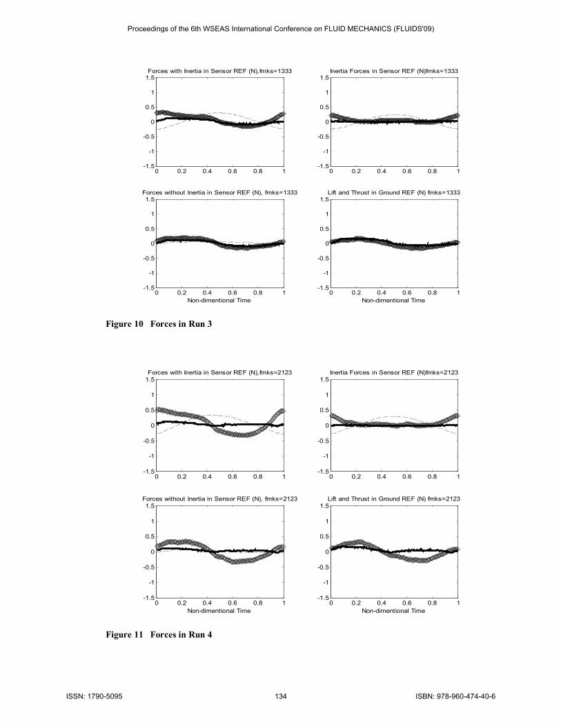
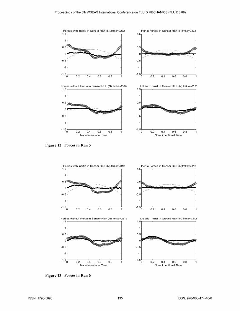
data including only one flapping cycle starting from the beginning of the downstroke are in fact the phase averaged values from 10 continuing flapping cycles. (In the titles of all Figures, fmks=wxyz denotes that flapping frequency f, spring1 stiffness m, spring2 stiffness k, and wing stiffness w, were in their state of w,x,y,z, respectively. ) Figure 7 shows the time history of wing rotation angle from the 1st to the 9th run, while Figure 8 to Figure 16 shows the forces in each run.
Each figure from Figure 8 to Figure16 contains 4 sub-figures: 1). forces recoded with wing inertia in sensor reference, 2). wing inertia force 3). forces in sensor reference with inertia subtracted. 4). Lift and Thrust in Ground reference. The thickest line represents the Fx, second thick line represents Fy, and thin line represents Fz in both sensor and ground reference frames. (The thickest line represents fx, thick line for fy and thin line fz in first 3 sub-Figures. The thick and thin line in last sub-Figures represent for Lift and Thrust in Ground Reference).
0 0.5 1
-50
0
50
Rotation Angle (deg), fmks=1111
0 0.5 1
-50
0
50
Rotation Angle (deg), fmks=1222
0 0.5 1
-50
0
50
Rotation Angle (deg), fmks=1333
0 0.5 1
-50
0
50
Rotation Angle (deg), fmks=2123
0 0.5 1
-50
0
50
Rotation Angle (deg), fmks=2232
0 0.5 1
-50
0
50
Rotation Angle (deg), fmks=2312
0 0.5 1
-50
0
50
Rotation Angle (deg), fmks=3132
0 0.5 1
-50
0
50
Rotation Angle (deg), fmks=3213
0 0.5 1
-50
0
50
Rotation Angle (deg), fmks=3322
Figure 7 Wing Rotation Angle
Proceedings of the 6th WSEAS International Conference on FLUID MECHANICS (FLUIDS'09)
ISSN: 1790-5095 132 ISBN: 978-960-474-40-6
0 0.2 0.4 0.6 0.8 1-1.5
-1
-0.5
0
0.5
1
1.5Forces with Inertia in Sensor REF (N),fmks=1111
0 0.2 0.4 0.6 0.8 1-1.5
-1
-0.5
0
0.5
1
1.5Inertia Forces in Sensor REF (N)fmks=1111
0 0.2 0.4 0.6 0.8 1-1.5
-1
-0.5
0
0.5
1
1.5Forces without Inertia in Sensor REF (N), fmks=1111
Non-dimentional Time0 0.2 0.4 0.6 0.8 1
-1.5
-1
-0.5
0
0.5
1
1.5Lift and Thrust in Ground REF (N) fmks=1111
Non-dimentional Time
Figure 8 Forces in Run 1
0 0.2 0.4 0.6 0.8 1-1.5
-1
-0.5
0
0.5
1
1.5Forces with Inertia in Sensor REF (N),fmks=1222
0 0.2 0.4 0.6 0.8 1-1.5
-1
-0.5
0
0.5
1
1.5Inertia Forces in Sensor REF (N)fmks=1222
0 0.2 0.4 0.6 0.8 1-1.5
-1
-0.5
0
0.5
1
1.5Forces without Inertia in Sensor REF (N), fmks=1222
Non-dimentional Time0 0.2 0.4 0.6 0.8 1
-1.5
-1
-0.5
0
0.5
1
1.5Lift and Thrust in Ground REF (N) fmks=1222
Non-dimentional Time
Figure 9 Forces in Run 2
Proceedings of the 6th WSEAS International Conference on FLUID MECHANICS (FLUIDS'09)
ISSN: 1790-5095 133 ISBN: 978-960-474-40-6
0 0.2 0.4 0.6 0.8 1-1.5
-1
-0.5
0
0.5
1
1.5Forces with Inertia in Sensor REF (N),fmks=1333
0 0.2 0.4 0.6 0.8 1-1.5
-1
-0.5
0
0.5
1
1.5Inertia Forces in Sensor REF (N)fmks=1333
0 0.2 0.4 0.6 0.8 1-1.5
-1
-0.5
0
0.5
1
1.5Forces without Inertia in Sensor REF (N), fmks=1333
Non-dimentional Time0 0.2 0.4 0.6 0.8 1
-1.5
-1
-0.5
0
0.5
1
1.5Lift and Thrust in Ground REF (N) fmks=1333
Non-dimentional Time
Figure 10 Forces in Run 3
0 0.2 0.4 0.6 0.8 1-1.5
-1
-0.5
0
0.5
1
1.5Forces with Inertia in Sensor REF (N),fmks=2123
0 0.2 0.4 0.6 0.8 1-1.5
-1
-0.5
0
0.5
1
1.5Inertia Forces in Sensor REF (N)fmks=2123
0 0.2 0.4 0.6 0.8 1-1.5
-1
-0.5
0
0.5
1
1.5Forces without Inertia in Sensor REF (N), fmks=2123
Non-dimentional Time0 0.2 0.4 0.6 0.8 1
-1.5
-1
-0.5
0
0.5
1
1.5Lift and Thrust in Ground REF (N) fmks=2123
Non-dimentional Time
Figure 11 Forces in Run 4
Proceedings of the 6th WSEAS International Conference on FLUID MECHANICS (FLUIDS'09)
ISSN: 1790-5095 134 ISBN: 978-960-474-40-6
0 0.2 0.4 0.6 0.8 1-1.5
-1
-0.5
0
0.5
1
1.5Forces with Inertia in Sensor REF (N),fmks=2232
0 0.2 0.4 0.6 0.8 1-1.5
-1
-0.5
0
0.5
1
1.5Inertia Forces in Sensor REF (N)fmks=2232
0 0.2 0.4 0.6 0.8 1-1.5
-1
-0.5
0
0.5
1
1.5Forces without Inertia in Sensor REF (N), fmks=2232
Non-dimentional Time0 0.2 0.4 0.6 0.8 1
-1.5
-1
-0.5
0
0.5
1
1.5Lift and Thrust in Ground REF (N) fmks=2232
Non-dimentional Time
Figure 12 Forces in Run 5
0 0.2 0.4 0.6 0.8 1-1.5
-1
-0.5
0
0.5
1
1.5Forces with Inertia in Sensor REF (N),fmks=2312
0 0.2 0.4 0.6 0.8 1-1.5
-1
-0.5
0
0.5
1
1.5Inertia Forces in Sensor REF (N)fmks=2312
0 0.2 0.4 0.6 0.8 1-1.5
-1
-0.5
0
0.5
1
1.5Forces without Inertia in Sensor REF (N), fmks=2312
Non-dimentional Time0 0.2 0.4 0.6 0.8 1
-1.5
-1
-0.5
0
0.5
1
1.5Lift and Thrust in Ground REF (N) fmks=2312
Non-dimentional Time
Figure 13 Forces in Run 6
Proceedings of the 6th WSEAS International Conference on FLUID MECHANICS (FLUIDS'09)
ISSN: 1790-5095 135 ISBN: 978-960-474-40-6

0 0.2 0.4 0.6 0.8 1-1.5
-1
-0.5
0
0.5
1
1.5Forces with Inertia in Sensor REF (N),fmks=3132
0 0.2 0.4 0.6 0.8 1-1.5
-1
-0.5
0
0.5
1
1.5Inertia Forces in Sensor REF (N)fmks=3132
0 0.2 0.4 0.6 0.8 1-1.5
-1
-0.5
0
0.5
1
1.5Forces without Inertia in Sensor REF (N), fmks=3132
Non-dimentional Time0 0.2 0.4 0.6 0.8 1
-1.5
-1
-0.5
0
0.5
1
1.5Lift and Thrust in Ground REF (N) fmks=3132
Non-dimentional Time
Figure 14 Forces in Run 7
0 0.2 0.4 0.6 0.8 1-1.5
-1
-0.5
0
0.5
1
1.5Forces with Inertia in Sensor REF (N),fmks=3213
0 0.2 0.4 0.6 0.8 1-1.5
-1
-0.5
0
0.5
1
1.5Inertia Forces in Sensor REF (N)fmks=3213
0 0.2 0.4 0.6 0.8 1-1.5
-1
-0.5
0
0.5
1
1.5Forces without Inertia in Sensor REF (N), fmks=3213
Non-dimentional Time0 0.2 0.4 0.6 0.8 1
-1.5
-1
-0.5
0
0.5
1
1.5Lift and Thrust in Ground REF (N) fmks=3213
Non-dimentional Time
Figure 15 Forces in Run 8
Proceedings of the 6th WSEAS International Conference on FLUID MECHANICS (FLUIDS'09)
ISSN: 1790-5095 136 ISBN: 978-960-474-40-6
0 0.2 0.4 0.6 0.8 1-1.5
-1
-0.5
0
0.5
1
1.5Forces with Inertia in Sensor REF (N),fmks=3322
0 0.2 0.4 0.6 0.8 1-1.5
-1
-0.5
0
0.5
1
1.5Inertia Forces in Sensor REF (N)fmks=3322
0 0.2 0.4 0.6 0.8 1-1.5
-1
-0.5
0
0.5
1
1.5Forces without Inertia in Sensor REF (N), fmks=3322
Non-dimentional Time0 0.2 0.4 0.6 0.8 1
-1.5
-1
-0.5
0
0.5
1
1.5Lift and Thrust in Ground REF (N) fmks=3322
Non-dimentional Time
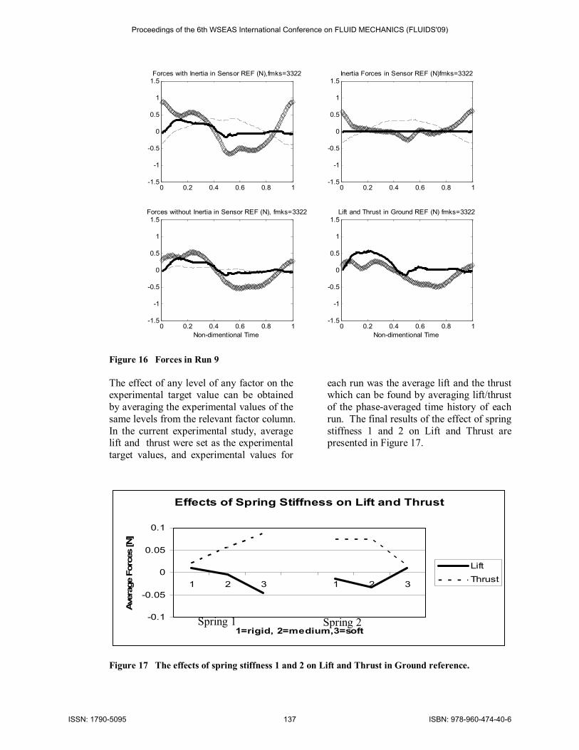
Figure 16 Forces in Run 9 The effect of any level of any factor on the experimental target value can be obtained by averaging the experimental values of the same levels from the relevant factor column. In the current experimental study, average lift and thrust were set as the experimental target values, and experimental values for
each run was the average lift and the thrust which can be found by averaging lift/thrust of the phase-averaged time history of each run. The final results of the effect of spring stiffness 1 and 2 on Lift and Thrust are presented in Figure 17.
Effects of Spring Stiffness on Lift and Thrust
-0.1
-0.05
0
0.05
0.1
1 2 3 1 2 3
1=rigid, 2=medium,3=soft
Ave
rage
For
ces
[N]
LiftThrust
Figure 17 The effects of spring stiffness 1 and 2 on Lift and Thrust in Ground reference.
Spring 1 Spring 2
Proceedings of the 6th WSEAS International Conference on FLUID MECHANICS (FLUIDS'09)
ISSN: 1790-5095 137 ISBN: 978-960-474-40-6
Spring stiffness is directly related to the wing rotation angle in the current experimental device. A stiffer spring will lead to a smaller rotation angle. However, wing rotation angle is a complementary angle of AOA. Therefore a stiffer spring will lead to a larger AOA. This means, the question of the effects of mean AOA on Lift and Thrust can be converted to the question of the effects of spring stiffness on Lift and Thrust. In other words, the effects of spring stiffness on Lift and Thrust are
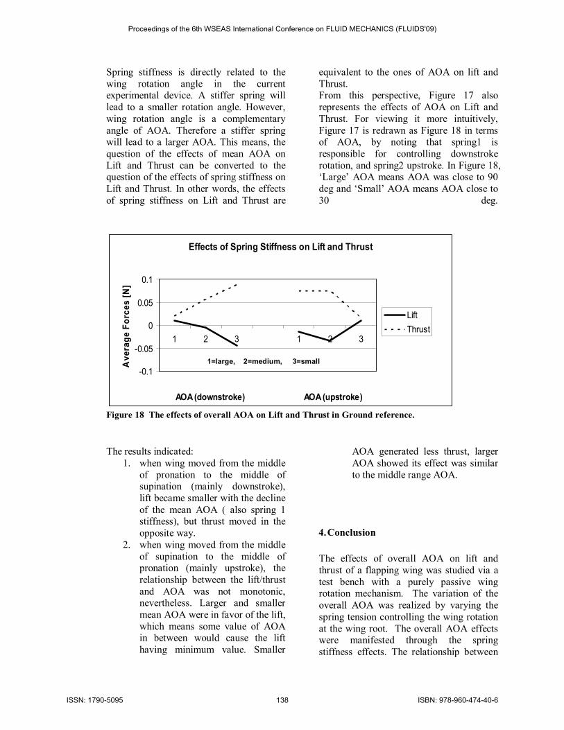
equivalent to the ones of AOA on lift and Thrust. From this perspective, Figure 17 also represents the effects of AOA on Lift and Thrust. For viewing it more intuitively, Figure 17 is redrawn as Figure 18 in terms of AOA, by noting that spring1 is responsible for controlling downstroke rotation, and spring2 upstroke. In Figure 18, ‘Large’ AOA means AOA was close to 90 deg and ‘Small’ AOA means AOA close to 30 deg.
Effects of Spring Stiffness on Lift and Thrust
-0.1
-0.05
0
0.05
0.1
1 2 3 1 2 3
AOA (downstroke) AOA (upstroke)
Ave
rage
For
ces
[N]
LiftThrust
Figure 18 The effects of overall AOA on Lift and Thrust in Ground reference.
The results indicated: 1. when wing moved from the middle
of pronation to the middle of supination (mainly downstroke), lift became smaller with the decline of the mean AOA ( also spring 1 stiffness), but thrust moved in the opposite way.
2. when wing moved from the middle of supination to the middle of pronation (mainly upstroke), the relationship between the lift/thrust and AOA was not monotonic, nevertheless. Larger and smaller mean AOA were in favor of the lift, which means some value of AOA in between would cause the lift having minimum value. Smaller
AOA generated less thrust, larger AOA showed its effect was similar to the middle range AOA.
4. Conclusion The effects of overall AOA on lift and thrust of a flapping wing was studied via a test bench with a purely passive wing rotation mechanism. The variation of the overall AOA was realized by varying the spring tension controlling the wing rotation at the wing root. The overall AOA effects were manifested through the spring stiffness effects. The relationship between
1=large, 2=medium, 3=small
Proceedings of the 6th WSEAS International Conference on FLUID MECHANICS (FLUIDS'09)
ISSN: 1790-5095 138 ISBN: 978-960-474-40-6
AOA and lift/thrust was found being monotonic in downstroke, but not the case
in upstroke.
Reference:
[1] R. Wootton, "Aerodynamics: From insects to microvehicles," Nature, vol. 403, pp. 144-145, 2000.
[2] A. R. Ennos, "The Inertial Cause of Wing Rotation in Diptera," J Exp Biol, vol. 140, pp. 161-169, November 1, 1988 1988b.
[3] Z. J. Wang, "Dissecting Insect Flight," Annu. Rev.Fluid Mech., vol. 2005, pp. 183-210, 2005.
[4] A. J. Bergou, S. Xu, and Z. J. Wang, "Passive wing pitch reversal in insect flight," Journal of Fluid Mechanics, vol. 591, pp. 321-337, Nov 2007.
[5] M. H. Dickinson and K. G. Gotz, "Unsteady aerodynamic performance of model wings at low Reynolds numbers," J Exp Biol, vol. 174, pp. 45-64, January 1, 1993 1993b.
[6] M. Dickinson, "The Effects of Wing Rotation on Unstead Aerodynamics Performance at Low Reynolds Numbers," J Exp Biol, vol. 192, pp. 179-206, July 1, 1994 1994.
[7] C. v. d. Berg and C. P. Ellington, "The Vortex Wake of a "Hovering" Model Hawkmoth,"
Phil. Trans. R. Soc. Lond, vol. 352, pp. 317-328, 1984b.
[8] J. R. Usherwood and C. P. Ellington, "The aerodynamics of revolving wings I. Model hawkmoth wings," J Exp Biol, vol. 205, pp. 1547-1564, June 1, 2002 2002a.
[9] W. J. Maybury and F.-O. Lehmann, "The fluid dynamics of flight control by kinematic phase lag variation between two robotic insect wings," J Exp Biol, vol. 207, pp. 4707-4726, December 15, 2004 2004.
[10] A. R. Ennos, "The Importance of Torsion in the Design of Insect Wings," J Exp Biol, vol. 140, pp. 137-160, November 1, 1988 1988a.
[11] S. A. Combes and T. L. Daniel, "Flexural stiffness in insect wings I. Scaling and the influence of wing venation," Journal of Experimental Biology, vol. 206, pp. 2979-2987, Sep 2003.
[12] D. J. S. Newman and R. J. Wootton, "An Approach to the Mechanics of Pleating in Dragonfly Wings," J Exp Biol, vol. 125, pp. 361-372, 1986.
Proceedings of the 6th WSEAS International Conference on FLUID MECHANICS (FLUIDS'09)
ISSN: 1790-5095 139 ISBN: 978-960-474-40-6