effective length factor for column in frame with girders ... · amount of elastic foundation...
TRANSCRIPT

International Journal of Scientific & Engineering Research, Volume 5, Issue 12, December-2014ISSN 2229-5518
IJSER © 2014http://www.ijser.org
Effective Length Factor for Column in Frame withGirders on Elastic Foundation
F.Y. Al-Ghalibi
Abstract— This paper considered the effects of elastic foundation on effective length factor calculations using subassembly model for bracedand unbraced frames, the girders far ends condition are modeled as rigid, fixed, or hinged. The derivation is under same assumptions of conven-tional effective length factor (K-factor) using two approaches. The first approach considered the effects of elastic foundation and girders far endsconditions by depending on 1 and 2 parameters, the general modified K-factor equations have been derived for braced and unbraced frame us-ing slop-deflection method. In the second approach, formulae of stiffness modification parameter ‘ ’, which modify the relative columns to beamsstiffness factor ‘G’ are calculated with direct use of G in the US National codes alignment chart. Approximate modified K-factor formulae are pro-posed for braced and unbraced frames. The Approximate proposed modified K-factor equations are suitable for practical use. Numerical exam-ples are presented to illustrate the effects of elastic foundation taken into consideration girders far ends conditions. The Results showed that theamount of elastic foundation modulus influenced the modified K-factor values and the stiffness of elastic foundation must be taken into account inK-factor calculations. Generally, modified K-factor values decrease with increasing of stiffness of the elastic foundation.
Index Terms— Stability, stiffness, elastic foundation, modified K-factor, stability functions, braced-frame, unbraced frame.
—————————— ——————————
1 INTRODUCTIONHE importance of K-factor calculation has increased sincethe middle of the last century. K-factor formulations andapplications are widely used in U.S. specifications such as
AISC-LRFD, AISC-ASD, ACI (318), AASHTO and many text-books. In the structural engineering, the calculation process ofeffective length factors are one of the most important applica-tions spatially in the field of second order analysis and mem-bers slenderness. K-factor is widely used in the field of ad-vanced structural analysis, design, buckling issues and struc-tural stability. The studies, research and many referencesshowed K-factor importance and effects on the behavior ofstructural analysis and design. The value of K-factor is varia-ble and it’s depending upon many factors, those factors arerelated to structure’s dimensions, types of supports, frame’sgeometry, shape of members, type of member’s material, andloading’s case. The derivation of K-factor equation is based oncalculation assumptions, these assumptions are simplified themodeling and calculation of K-factor. For example, the as-sumption of simultaneously buckling of all columns in onestory with an idealized subassembly model used to preparethe alignment charts, this assumption was proposed by Julianand Lawrence(1959). LeMessurier(1977)modified Julian andLawrence’s assumption based on considering the columns in aone story buckle simultaneously and the strong columnbraced the weak column or that carry high axial load. Depend-ing on this assumption, LeMessurier applied some types ofcorrection factor to the alignment charts.
————————————————
University Assistance Lecturer, Structures and Water Resources Department,College of Engineering, Kufa University, AN-Najaf city, AN- Najaf province,Iraq. Tel: +964 781 9877878, E-mail: [email protected].
Lui(1992)proposed simple and more effective method in eval-uating the K-factor in sway frame, the method consideredboth instability of member and frame. Hu and Lai (1986) pro-posed a computer programming method to calculate the K-factors. In that computer program, the modeling of elementwas considered the effects of axial force for typical offshorestructures with ends rotational spring and translational elasticsprings at a distance from element end. Yura(1971)studied theK-factor calculation for unbraced frame, his strategy involvedreducing the calculation process by modeling the problem asan equivalent pinned-ends braced columns. Duan andChen(1988)proposed a modification to K-factor’s calculationfor braced framed column to increase the accuracy of K-factor’s calculation by presenting a modification to G factorswhich are used in US National codes alignment charts by con-sidering the effect of columns far-ends condition in the aboveand below the column under consideration. Also, Duan andChen (1988) modified K-factor calculation for unbracedframed column by taking into account the effect of columnsfar ends condition in the above and below the considered col-umn. Their work involved modifying G factors used in USNational codes alignment charts. Chen et al(1993a) suggesteda new method to calculate K-factor for braced and unbracedcolumn in frame restrained by tapered girder with variousgirders far end conditions. The model improved the conven-tional G factor by girder stiffness modification parameter .Chen et al (1993a) discussed the ACI (318-89) simplified equa-tions and indicated some comments and limitations used forsimplified ACI-code K-factor equations. Dumonteil(1992)discussed the exact conventional K-factor formulae forbraced and unbraced columns and check the accuracy of K-factor approximate equations. Dumonteil (1999)discussedsome historical K-factor equations for braced and unbracedcolumns. He checked the accuracy with the exact form for theFrench “CM 66” approximate formulae for braced and un-
T IJSER
1259

International Journal of Scientific & Engineering Research Volume 5, Issue 12, December-2014ISSN 2229-5518
IJSER © 2014http://www.ijser.org
braced columns, Donnell’s approximate formulae and New-mark’s approximate formulae for braced column.The analysis of beams on elastic foundation was well estab-lished in the literature. The differential equation approachused by Hetenyi (1946) is practical for engineering purposes.In structural buildings, some elements may be interacting withelastic foundation; such interaction affected the accuracy of K-factor calculation. This paper presents the exact and approxi-mate modified K-factor equations for braced and unbracedcolumn in frame with girders on elastic foundation. The gird-ers far ends are modeled as rigid, fixed, and hinged. The mod-ified K-factor exact formulae derived by using two approach-es, the first approach considered the parameter n which isderived using subassembly model (Fig.1). The value of pa-rameter n is varying with frame’s case (braced or unbraced),elastic foundation stiffness parameter , and girders far endscondition. The second approach considered the conventionalalignment charts for prismatic girders, so that the original Gfactor can’t use directly. The present study developed G factorused in US codes alignment charts by depending on stiffnessparameter n which is derived for girders on elastic founda-tion with various far end conditions by dividing the bendingstiffness of girder on the elastic foundation on the bendingstiffness of ordinary member. The proposed modification to Gfactor allow to use the US cods alignment charts for column inframe with girders on elastic foundation and various far endconditions. The exact modified K-factor formulae are derivedaccording to the following assumptions:1. Columns buckle simultaneously.2. All members are elastic and prismatic cross section.3. All girders have negligible axial force.4. All column ends are rigid, while the girders far end are
modeled as rigid, fixed or hinged.5. All columns have equal stiffness parameter EI/PL .6. For braced frame, angles of rotation at opposite girder
ends have an equal value and produce single bendingcurvature as shown in Fig.1(B); whereas for unbracedframe, angle of rotation at opposite girder ends also haveequal value and but produce reverse bending curvature asshown in Fig.1(C).
7. Distribution of resistance of joint is proportion to L/I oftwo columns in above and below the joint.
Fig.1.Subassembly model for a frame with girders on elastic foundation,(A) modified model, (B) modified braced frame subassembly model, (C)modified unbraced frame subassembly model
.
Fig. 2. Alignment charts of the US National cods, (A) braced frame, (B)unbraced frame
2 EXACT MODIFIED K-FACTOR EQUATIONS (EXACT FIRSTAPPROACH)
The differential equation of girder on elastic foundation can begiven as:
0ykdx
ydEI s4
4 (1)
From the solution of Eq.1, the stiffness coefficients of girder onelastic foundation (S &Sc ) can be obtained as follow:
)(Sin)(Sinh
)(Cos)(Sin)(Cosh)(Sinh2S
22 (2)
)(Sin)(Sinh
)(Cos)(Sinh)(Cosh)(Sin2Sc
22 (3)
Where parameter is given by:
4 sEI4
k (4)
Where, ks is an elastic foundation parameter
2.1 Braced frameAt the buckling load, the columns have an axial force parame-ter
=2
K1
and the stability functions KK SCandS stated else-where(Duan and Chen, 1988, Duan and Chen, 1989) as shownin Eq.5 and Eq.6:
KSin
KKCos22
KCos
KKSin
KS
2
K (5)
IJSER
1260
International Journal of Scientific & Engineering Research Volume 5, Issue 12, December-2014ISSN 2229-5518
IJSER © 2014http://www.ijser.org
KSin
KKCos22
KSin
KKSC
2
K (6)
By using the slop-deflection equations for the subassemblymodel for column in braced frame on elastic foundation withvariable girders far end conditions, the following relation canbe achieved:
0GASCGAS
GBSGBSC
KK1
K2K (7)
Eq. 7 can be written as:
0SCSGBGA
SGBGA
2K
2K
21K
21 (8)
The basic equation for the stability analysis of sway-preventedframe on the elastic foundation with variable girder far endsconditions resulted from Eq.8 can be given as:
01K/
K2/tan2
K/tanK/1GBGAK/GAGB
21
2
21 (9)
Where
g
C
LEIL
EI
G (10)
The parameter n for braced frame can be given as:For rigid girder far end:
)(Sin)(Sinh)(Cos)(Cosh
2SCSnn
nnnnnn (11)
For fixed girder far end:
)(Sin)(Sinh
)(Cos)(Sin)(Cosh)(Sinh2S
n2
n2
nnnnnnn (12)
For hinged girder far end:
)(Cos)(Sin)(Cosh)(Sinh
)(Cos)(Cosh2
SSCS
nnnn
n2
n2
nn
2n
2n
n (13)
2.2 Unbraced frameBy using the slop-deflection equations for the subassemblymodel for column in unbraced frame with girders on elasticfoundation have variable girders far ends condition, the fol-lowing relation can be obtained:
0
K21SCS2)SCS()SCS(
SCSSCSGA
SCSSGB
SC
2
KKKKKK
KKKK1
KKK2
K
(14)
Eq.14 can be written in the following form:
)15(0SCSK
KSSSC
GBGASC2S2
KGBGA3
2K
2K
2
2
K2
K2
K21
KK
221
The basic equation for stability analysis of unbraced frame onelastic foundation with variable girder far ends conditionsresulted from Eq.15 can be given by:
0)K/tan(
K/
GAGB2
K/GAGB
21
212
(16)
The parameter n for unbraced frame can be given as:For rigid girder far end
)(Sin)(Sinh)(Cos)(Cosh
2SCSnn
nnnnnn (17)
For fixed girder far end
)(Sin)(Sinh
)(Cos)(Sin)(Cosh)(Sinh2S
n2
n2
nnnnnnn (18)
For hinged girder far end
)(Cos)(Sin)(Cosh)(Sinh)(Cos)(Cosh2
SSCS
nnnn
n2
n2
nn
2n
2n
n (19)
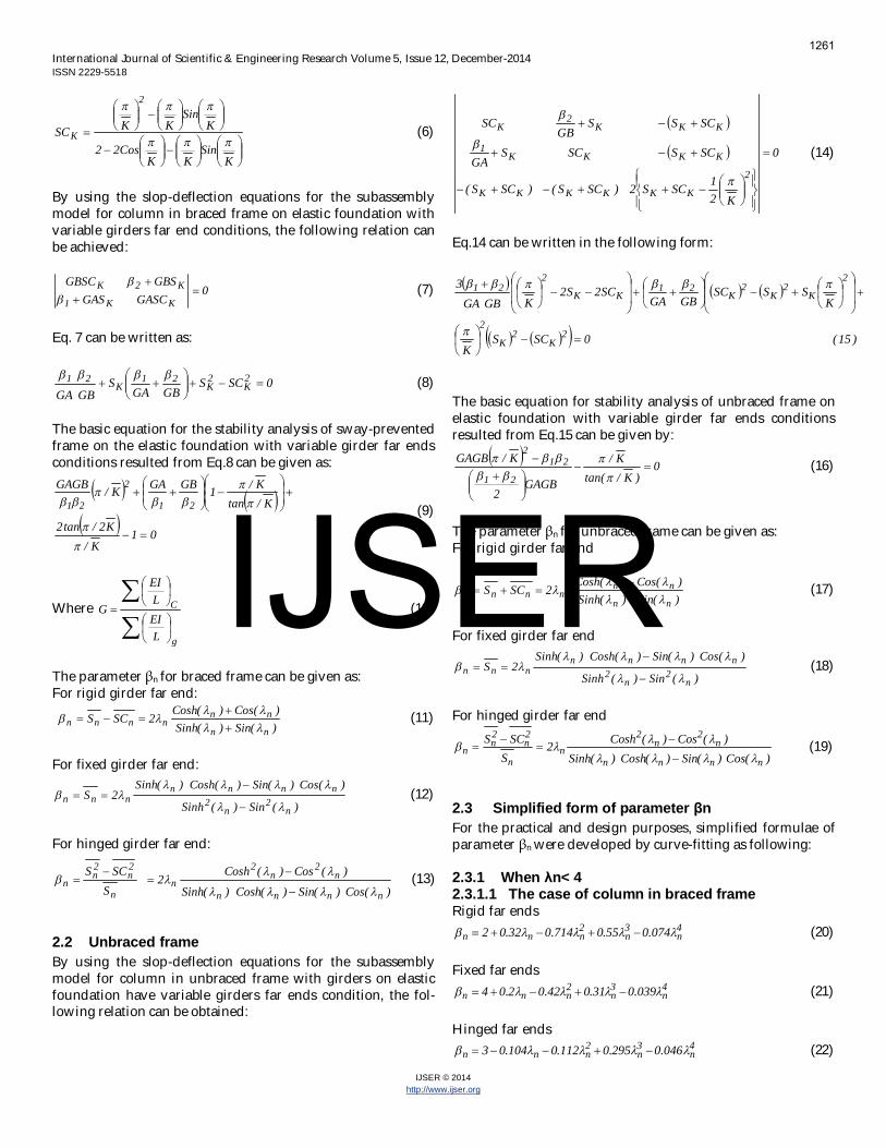
2.3 Simplified form of parameter nFor the practical and design purposes, simplified formulae ofparameter n were developed by curve-fitting as following:
2.3.1 When n< 42.3.1.1 The case of column in braced frameRigid far ends
4n
3n
2nnn 074.055.0714.032.02 (20)
Fixed far ends4n
3n
2nnn 039.031.042.02.04 (21)
Hinged far ends4n
3n
2nnn 046.0295.0112.0104.03 (22)
IJSER
1261

International Journal of Scientific & Engineering Research Volume 5, Issue 12, December-2014ISSN 2229-5518
IJSER © 2014http://www.ijser.org
2.3.1.2 The case of column in unbraced frameRigid far ends
3n
2nnn 04584.0066.00258.06 (23)
Fixed far ends4n
3n
2nnn 039.031.042.02.04 (24)
Hinged far ends4n
3n
2nnn 0474.03.0112.0104.03 (25)
2.3.2 When n 4In this case, the close form solution (Eq.s 11, 12, 13, 17, 18 and19) gives the following result:
1)(Cos)(Sin)(Cosh)(Sinh
)(Cos)(Cosh)(Sin)(Sinh)(Cos)(Cosh
)(Sin)(Sinh
)(Cos)(Sin)(Cosh)(Sinh)(Sin)(Sinh)(Cos)(Cosh
nnnn
n2
n2
nn
nn
n2
n2
nnnn
nn
nn
(26)
2.3.2.1 Case of column in braced or unbraced frameThe parameter n can be obtained by according to Eq. 26.Then, Eq.s 11, 12, 13, 17, 18 and 19 can be written as shown inEq.27:
nn 2endsfarhinged
endsfarfixedendsfarrigid
(27)
From Eq.s 20 to 25, it can be concluded that, when the parame-ter n approach to zero, Eq.s 20 to 25are reducing to the follow-ing form:For braced column
endfarhingedfor3endfarfixedfor4endfarrigidfor2
n (28)
For unbraced column
endfarhingedfor3endfarfixedfor4endfarrigidfor6
n (29)
Eq.s 28 and 29 considered the effects of far end conditions ofprismatic girders without interaction between frame and elas-tic foundation. In the case of sway-prevented column withrigid girders far ends, Eq. 28 given that 1= 2=2, when substi-tute these beta values in Eq. 9 the resulted equation is as sameas the US National codes equation (AISC, 2012, AISC, 1989,ACI, 2014, AASHTO, 1989).Also,Eq.29 given that 1= 2=6 forsway-allowed frame with rigid girders far ends and when ap-ply these beta values inEq.16, the resulted equation is as same
as US National codes equation (AISC, 2012, AISC, 1989, ACI,2014, AASHTO, 1989) for sway-allowed column.
3 MODIFIED ALIGNMENT CHART (EXACT SECONDAPPROACH)
The modified G -factor equation is proposed by Chen at el(1993a, 1993b) for the case of column in frame restrained bytapered girders using stiffness modification parameter. Thisparagraph introduces a modified G -factor used in the currentalignment charts of US National codes which enable the de-signer to calculate the modified K-factor by direct use of thealignment charts (Fig. 2).The G factor equation which consid-ered the effect of elastic foundation and girders far end condi-tion is given as:
ggg
ccc
L/IE
L/IEG (30)
Where : is girder on elastic foundation stiffness modificationparameter.
3.1 Exact form of stiffness modification parameterThe girder stiffness modification parameter is calculated forbraced and unbraced frames by dividing the bending stiffnessof girder on elastic foundation on the bending stiffness of or-dinary girder not interacted with elastic foundation. The pa-rameter is considered the effects of girder far end conditionand elastic foundation stiffness.
For braced columnsWhen girder far end is rigid
)(Sin)(Sinh)(Cos)(Cosh
2SCS
nn
nnn (31)
When girder far end is fixed
)(Sin)(Sinh
)(Cos)(Sin)(Cosh)(Sinh2S
n2
n2
nnnnn (32)
When girder far end is hinged
)(Cos)(Sin)(Cosh)(Sinh)(Cos)(Cosh
S2SCS
nnnn
n2
n2
n
22
(33)
For unbraced columnsWhen girder far end is rigid
)(Sin)(Sinh)(Cos)(Cosh
36SCS
nn
nnn (34)
When girder far end is fixed
)(Sin)(Sinh
)(Cos)(Sin)(Cosh)(Sinh36
S
n2
n2
nnnnn (35)
When girder far end is hinged
)(Cos)(Sin)(Cosh)(Sinh
)(Cos)(Cosh3S6
SCS
nnnn
n2
n2
n22
(36)
IJSER
1262
International Journal of Scientific & Engineering Research Volume 5, Issue 12, December-2014ISSN 2229-5518
IJSER © 2014http://www.ijser.org
3.2 Simplified form of stiffness modification parameterFor the practical and design purposes, a simplified formulae ofstiffness modification parameter can be obtained by compareEq.s 11,12,13,17,18 and 19 with Eq.s 31 to 36.The followingrelation between parameter and parameter can be con-cluded as followFor braced frame
2 (37)
For unbraced frame6
(38)
By using Eq.s 37and 38, the simplified form of stiffness modi-fication parameter can be obtained as:
3.2.1 When n< 43.2.1.1 The case of column in braced frameRigid far end 4
n3n
2nnn 037.0275.0357.016.01 (39)
Fixed far end 4n
3n
2nnn 0194.0155.021.01.02 (40)
Hinged far end 4n
3n
2nnn 023.01475.0056.0052.05.1 (41)
3.2.1.2 The case of column in unbraced frame
Rigid far end 3n
2nnn 00764.0011.00043.01 (42)
Fixed far end 4n
3n
2nnn 0065.0052.0071.0034.066.0 (43)
Hinged far end 4n
3n
2nnn 0079.005.00187.00173.05.0
(44)
3.2.2 When n 43.2.2.1 The case of column in braced frameThe parameter n can be obtained by substitute Eq. 37 in Eq.27
nnendfarhinged
endfarfixedendfarrigid
(45)
3.2.2.2 The case of column in unbraced frameThe parameter n can be obtained by substitute Eq. 38 in Eq.27
3/endfarhinged
endfarfixedendfarrigid
nn (46)
When parameter n approach to zero (the case of no interac-tion between girder and elastic foundation) Eq.s 39 to 44is re-ducing to the following form:For braced column
endfarhingedfor5.1endfarfixedfor2endfarrigidfor1
n (47)
For unbraced column
endfarhingedfor5.0endfarfixedfor3/2endfarrigidfor1
n (48)
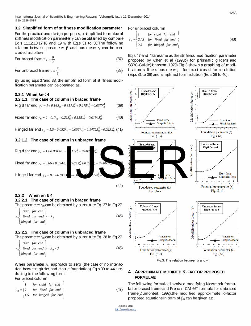
Eq.s 47 and 48aresame as the stiffness modification parameterproposed by Chen et al (1993b) for prismatic girders andSSRC-Guide(Johnston, 1979).Fig.3 shows a graphing of modi-fication stiffness parameter n for exact closed form solution(Eq.s 31 to 36) and simplified form solution (Eq.s 39 to 46).
Fig.3. The relation between and
4 APPROXIMATE MODIFIED K-FACTOR PROPOSEDFORMULAE
The following formulae involved modifying Newmark formu-la for braced frame and French “CM 66” formula for unbracedframe(Dumonteil, 1992),the modified approximate K-factorproposed equations in term of n can be given as:
IJSER
1263

International Journal of Scientific & Engineering Research Volume 5, Issue 12, December-2014ISSN 2229-5518
IJSER © 2014http://www.ijser.org
For braced column
2B1A
2B1A41.0G41.0G205.0G205.0GK (49)
For unbraced column
5.7)GG(6
5.7)GG(24GG6.57
K
2
B
1
A2
B
1
A
21
BA
(50) (50)
The exact Eq.s 9, 16 and approximate Eq.s 49 and 50 usedwhen the two adjacent girders in one joint have same value ofelastic foundation parameter . For the general case when thetwo adjacent girders in one joint have different value of elasticfoundation parameter , the following formulae can be used:For braced column
82.0G82.0G
41.0G41.0GKBA
BA (51)
For unbraced column
5.7GG5.7)GG(4GG6.1K
BA
BABA (52)
Eq.s 51, and 52 can be considered as approximate solution ofthe following general case equations (Eq.s 53 and 54).For braced column
01K/
K2/tan2
K/tan
K/12
GBGAK/4GBGA 2
(53)
For unbraced column
0)K/tan(
K/
GBGA6
36K/GBGA2
(54)
When the two adjacent girders in one joint have same value ofelastic foundation parameter , Eq.s 49 and 50 can be writtenin term of n as:For braced column
2B1A
2B1A82.0G82.0G41.0G41.0GK (55)
For unbraced column
5.7GG
5.7)GG(4GG6.1
K
2
B
1
A2
B
1
A
21
BA
(56)
Graphing of Eq.s 9 and 49 for the case of braced frame andEq.s 16 and 50 for the case of unbraced frame with various
girder far end condition are shown bellow.
Fig. 4. The relation between modified effective length factor and GA forbraced column, (a) for rigid girders far end, (b) for fixed girders far end, (c)for hinged girders far end, GA=GB, 1= 2= 3= 4=
0 1 2 3 4 5 6 7 8 9 10 110.50
0.55
0.60
0.65
0.70
0.75
0.80
0.85
0.90
0.95
1.00
Eq. 9, lamda=0
Eq. 9, lamda=2
Eq. 9, lamda=4
Eq. 9, lamda=6
Eq.9, lamda=8
Proposed, Eq. 49
K
GA
a
0 1 2 3 4 5 6 7 8 9 10 110.50
0.55
0.60
0.65
0.70
0.75
0.80
0.85
0.90
0.95
Eq. 9, lamda=0
Eq. 9, lamda=2
Eq. 9, lamda=4
Eq. 9, lamda=6
Eq. 9, lamda=8
Proposed, Eq. 49
K
GA
b
0 1 2 3 4 5 6 7 8 9 10 110.50
0.55
0.60
0.65
0.70
0.75
0.80
0.85
0.90
0.95
Eq. 9, lamda=0
Eq. 9, lamda=2
Eq. 9, lamda=4
Eq. 9, lamda=6
Eq. 9, lamda=8
Proposed, Eq. 49
K
GA
c
IJSER
1264
International Journal of Scientific & Engineering Research Volume 5, Issue 12, December-2014ISSN 2229-5518
IJSER © 2014http://www.ijser.org
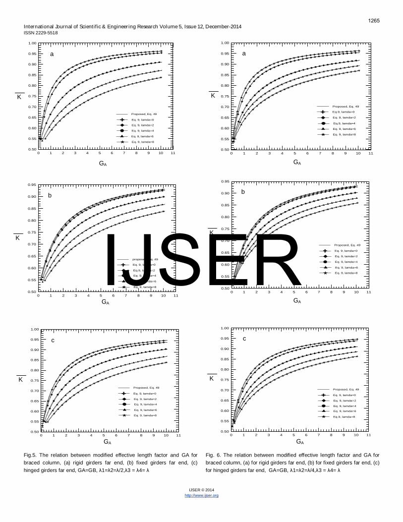
Fig.5. The relation between modified effective length factor and GA forbraced column, (a) rigid girders far end, (b) fixed girders far end, (c)hinged girders far end, GA=GB, 1= 2= /2, 3 = 4=
Fig. 6. The relation between modified effective length factor and GA forbraced column, (a) for rigid girders far end, (b) for fixed girders far end, (c)for hinged girders far end, GA=GB, 1= 2= /4, 3 = 4=
0 1 2 3 4 5 6 7 8 9 10 110.50
0.55
0.60
0.65
0.70
0.75
0.80
0.85
0.90
0.95
1.00
Eq. 9, lamda=0
Eq. 9, lamda=2
Eq. 9, lamda=4
Eq. 9, lamda=6
Eq. 9, lamda=8
Proposed, Eq. 49
K
GA
a
0 1 2 3 4 5 6 7 8 9 10 110.50
0.55
0.60
0.65
0.70
0.75
0.80
0.85
0.90
0.95
Eq. 9, lamda=0
Eq.9, lamda=2
Eq. 9, lamda=4
Eq. 9, lamda=6
Eq. 9, lamda=8
proposed, Eq. 49
K
GA
b
0 1 2 3 4 5 6 7 8 9 10 110.50
0.55
0.60
0.65
0.70
0.75
0.80
0.85
0.90
0.95
1.00
Eq. 9, lamda=0
Eq. 9, lamda=2
Eq. 9, lamda=4
Eq. 9, lamda=6
Eq. 9, lamda=8
Proposed, Eq. 49
K
GA
c
0 1 2 3 4 5 6 7 8 9 10 110.50
0.55
0.60
0.65
0.70
0.75
0.80
0.85
0.90
0.95
1.00
Eq.9, lamda=0
Eq. 9, lamda=2
Eq.9, lamda=4
Eq. 9, lamda=6
Eq. 9, lamda=8
Proposed, Eq. 49
K
GA
a
0 1 2 3 4 5 6 7 8 9 10 110.50
0.55
0.60
0.65
0.70
0.75
0.80
0.85
0.90
0.95
Eq. 9, lamda=0
Eq. 9, lamda=2
Eq. 9, lamda=4
Eq. 9, lamda=6
Eq. 9, lamda=8
Proposed, Eq. 49
K
GA
b
0 1 2 3 4 5 6 7 8 9 10 110.50
0.55
0.60
0.65
0.70
0.75
0.80
0.85
0.90
0.95
1.00
Eq. 9, lamda=0
Eq. 9, lamda=2
Eq. 9, lamda=4
Eq. 9, lamda=6
Eq.9, lamda=8
Proposed, Eq. 49
K
GA
c
IJSER
1265

International Journal of Scientific & Engineering Research Volume 5, Issue 12, December-2014ISSN 2229-5518
IJSER © 2014http://www.ijser.org
Fig. 7. The relation between modified effective length factor and GA forunbraced column, (a) for rigid girders far end, (b) for fixed girders far end,(c) for hinged girders far end, GA=GB, 1= 2= 3 = 4=
Fig. 8. The relation between modified effective length factor and GA forunbraced column, (a) for rigid girders far end, (b) for fixed girders far end,(c) for hinged girders far end, GA=GB, 1= 2= /2, 3 = 4=
0 1 2 3 4 5 6 7 8 9 10 111.1
1.2
1.3
1.4
1.5
1.6
1.7
1.8
1.9
2.0
2.1
2.2
2.3
2.4
2.5
2.6
Eq. 16, lamda=0
Eq. 16, lamda=2
Eq. 16, lamda=4
Eq. 16, lamda=6
Eq. 16, lamda=8
Proposed, Eq. 50
K
GA
a
0 1 2 3 4 5 6 7 8 9 10 111.1
1.2
1.3
1.4
1.5
1.6
1.7
1.8
1.9
2.0
2.1
2.2
2.3
2.4
2.5
2.6
Eq. 16, lamda=0
Eq. 16, lamda=2
Eq. 16, lamda=4
Eq. 16, lamda=6
Eq. 16, lamda=8
Proposed, Eq. 50
K
GA
b
0 1 2 3 4 5 6 7 8 9 10 111.1
1.2
1.3
1.4
1.5
1.6
1.7
1.8
1.9
2.0
2.1
2.2
2.3
2.4
2.5
2.6
Eq. 16, lamda=0
Eq. 16, lamda=2
Eq.16, lamda=4
Eq. 16, lamda=6
Eq. 16, lamda=8
Proposed, Eq. 50
K
GA
c
0 1 2 3 4 5 6 7 8 9 10 111.1
1.2
1.3
1.4
1.5
1.6
1.7
1.8
1.9
2.0
2.1
2.2
2.3
2.4
2.5
2.6
2.7
Eq. 16, lamda=0
Eq. 16, lamda=2
Eq. 16, lamda=4
Eq. 16, lamda=6
Eq. 16, lamda=8
Proposed, Eq. 50
K
GA
b
0 1 2 3 4 5 6 7 8 9 10 111.1
1.2
1.3
1.4
1.5
1.6
1.7
1.8
1.9
2.0
2.1
2.2
2.3
2.4
2.5
2.6
2.7
Eq. 16, lamda=0
Eq. 16, lamda=2
Eq. 16, lamda=4
Eq. 16, lamda=6
Eq. 16, lamda=8
Proposed, Eq. 50
K
a
GA
0 1 2 3 4 5 6 7 8 9 10 111.1
1.2
1.3
1.4
1.5
1.6
1.7
1.8
1.9
2.0
2.1
2.2
2.3
2.4
2.5
2.6
2.7
2.8
Eq. 16, lamda=0
Eq. 16, lamda=2
Eq. 16, lamda=4
Eq. 16, lamda=6
Eq. 16, lamda=8
Proposed, Eq. 50
K
GA
c
IJSER
1266
International Journal of Scientific & Engineering Research Volume 5, Issue 12, December-2014ISSN 2229-5518
IJSER © 2014http://www.ijser.org
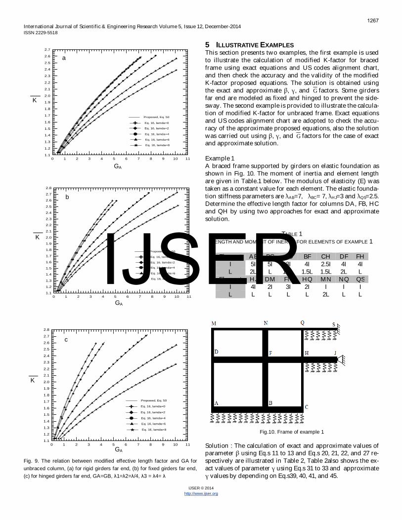
Fig. 9. The relation between modified effective length factor and GA forunbraced column, (a) for rigid girders far end, (b) for fixed girders far end,(c) for hinged girders far end, GA=GB, 1= 2= /4, 3 = 4=
5 ILLUSTRATIVE EXAMPLESThis section presents two examples, the first example is usedto illustrate the calculation of modified K-factor for bracedframe using exact equations and US codes alignment chart,and then check the accuracy and the validity of the modifiedK-factor proposed equations. The solution is obtained usingthe exact and approximate , , and G factors. Some girdersfar end are modeled as fixed and hinged to prevent the side-sway. The second example is provided to illustrate the calcula-tion of modified K-factor for unbraced frame. Exact equationsand US codes alignment chart are adopted to check the accu-racy of the approximate proposed equations, also the solutionwas carried out using , , and G factors for the case of exactand approximate solution.
Example 1A braced frame supported by girders on elastic foundation asshown in Fig. 10. The moment of inertia and element lengthare given in Table.1 below. The modulus of elasticity (E) wastaken as a constant value for each element. The elastic founda-tion stiffness parameters are AB=7, BC= 7, HJ=3 and QS=2.5.Determine the effective length factor for columns DA, FB, HCand QH by using two approaches for exact and approximatesolution.
TABLE 1LENGTH AND MOMENT OF INERTIA FOR ELEMENTS OF EXAMPLE 1
Element AB BC AD BF CH DF FHI 5I 5I 3I 4I 2.5I 4I 4IL 2L L 1.5L 1.5L 1.5L 2L L
Element HJ DM FN HQ MN NQ QSI 4I 2I 3I 2I I I IL L L L L 2L L L
Fig.10. Frame of example 1
Solution : The calculation of exact and approximate values ofparameter using Eq.s 11 to 13 and Eq.s 20, 21, 22, and 27 re-spectively are illustrated in Table 2, Table 2also shows the ex-act values of parameter using Eq.s 31 to 33 and approximate
values by depending on Eq.s39, 40, 41, and 45.
0 1 2 3 4 5 6 7 8 9 10 111.1
1.2
1.3
1.4
1.5
1.6
1.7
1.8
1.9
2.0
2.1
2.2
2.3
2.4
2.5
2.6
2.7
Eq. 16, lamda=0
Eq. 16, lamda=2
Eq. 16, lamda=4
Eq. 16, lamda=6
Eq. 16, lamda=8
Proposed, Eq. 50
K
GA
a
0 1 2 3 4 5 6 7 8 9 10 111.1
1.2
1.3
1.4
1.5
1.6
1.7
1.8
1.9
2.0
2.1
2.2
2.3
2.4
2.5
2.6
2.7
2.8
Eq. 16, lamda=0
Eq. 16, lamda=2
Eq. 16, lamda=4
Eq. 16, lamda=6
Eq. 16, lamda=8
Proposed, Eq. 50
K
GA
b
0 1 2 3 4 5 6 7 8 9 10 111.1
1.2
1.3
1.4
1.5
1.6
1.7
1.8
1.9
2.0
2.1
2.2
2.3
2.4
2.5
2.6
2.7
2.8
Eq. 16, lamda=0
Eq. 16, lamda=2
Eq. 16, lamda=4
Eq. 16, lamda=6
Eq. 16, lamda=8
Proposed, Eq. 50
K
GA
c
IJSER
1267

International Journal of Scientific & Engineering Research Volume 5, Issue 12, December-2014ISSN 2229-5518
IJSER © 2014http://www.ijser.org
TABLE 2EXACT AND APPROXIMATE VALUES OF AND OF EXAMPLE 1
Girder far end Exact App. Exact App.0 Rigid 2 2 1 17 Rigid 14 14 7 73 Hinged - - 2.982 2.96
2.5 Fixed - - 2.592 2.597
The values of G and G factors for each frame joint are tabulat-ed in Table 3 using Eq. 10 and Eq. 30 respectively. Parameter illustrated in Table 2 used in calculations of factors G exactand G approximate.
TABLE 3G AND OF EXAMPLE 1
Joint G G Exact G ApproximateA 0.8 0.1143 0.1143D 2 2 2B 0.356 0.0508 0.0508F 0.945 0.945 0.945C 0.34 0.0476 0.0476H 0.458 0.23 0.231Q 1 0.5568 0.556
For column DA, exact solution using Eq. 9
Using iteration exact K =0.689 or by using Eq. 53 exactK =0.689. By using alignment chart with direct use of G ,
689.0K .Approximate solution using Eq. 49
Approximate solution using Eq. 51
Approximate solution by using Eq.55
For column FB, exact solution using Eq.9 or Eq.53 K =0.637. Byusing alignment chart with direct use of G , 636.0K .Approximate solution by using Eq. 49 or 51 or 55 K =0.637.For column HC, exact solution using Eq.53 K =0.56. By usingalignment chart with direct use of G , 56.0K ..Approximatesolution using Eq. 51 567.0K .For column QH, exact solution using Eq.53 K =0.65. By usingalignment chart with direct use of G , 65.0K . Approximatesolution using Eq. 51 654.0K .
TABLE 4THE SUMMERY OF THE RESULTS OF EXAMPLE 1
Column DA FB HC QHK exact equation 0.689 0.637 0.56 0.65K alignment chart 0.689 0.636 0.56 0.65K approximate 0.692 0.637 0.567 0.654
Example 2For the unbraced frame shown in Fig.11, determine the effec-tive length factor for columns HA, JB, MC, ND, QF, RH, VNand WP by using two approaches for exact and approximatesolution. The elastic foundation stiffness parameters are AB=6,
BC= 6, CD=6, FH= 2 and NP=3. The values of moment of iner-tia and elements length are shown in Table 5 below and themodulus of elasticity (E) of each element is constant.
TABLE 5LENGTH AND MOMENT OF INERTIA FOR ELEMENTS OF EXAMPLE 2
Fig.11. Frame of example 2
Solution: The calculation of exact and approximate values ofparameter according to Eq.s 17 to 19 and Eq.s 23, 24, 25, and27 respectively are illustrated in Table 6, also the table showsthe exact values of parameter using Eq.s 34 to 36and approx-imate values according toEq.s42, 43, 44, and 46.
Element I L Element I LAB 3I 3L DN 4I 5LBC 3I 4L FH 2I 2LCD 3I 3L HJ 4I 3LAH 4I 5L JM 4I 4LBJ 6I 5L MN 4I 3LFQ I 3L QR 2I 2LHR 3I 3L RT 2I 3LJT 4I 3L TU 2I 4L
MU 4I 3L UV 2I 3LNV 4I 3L VW 2I 2LPW I 3L
G
692.014*41.08.02*41.02
14*205.08.02*205.02K
692.082.01143.082.0241.01143.041.02K
692.07*82.08.01*82.027*41.08.01*41.02K
01K/
K2/tan2K/tan
K/114
8.022K/
286.1 2 IJSER
1268

International Journal of Scientific & Engineering Research Volume 5, Issue 12, December-2014ISSN 2229-5518
IJSER © 2014http://www.ijser.org
TABLE 6EXACT AND APPROXIMATE VALUES OF AND OF EXAMPLE 2
Girder far end Exact App. Exact App.0 Rigid 6 6 1 16 Rigid 11.92 12 1.99 23 Rigid 6.717 6.72 1.12 1.122 Rigid 6.15 6.154 1.025 1.025
The values of G and G factors for each frame joint are tabulat-ed in Table 7 using Eq. 10 and Eq. 30 respectively. Parameter illustrated in Table 6 used in calculations of factors G exactand approximate.
TABLE 7G AND G OF EXAMPLE 2
For column HA, exact solution using Eq.54 K =1.185. By usingalignment chart with direct use of G , 185.1Kapproximate solution using Eq. 52 given as:
For columns JB and MC, Exact solution using Eq. 16
Using iteration exact K = 1.2137 or by using Eq. 54 exactK =1.2137. By using alignment chart with direct use of G ,
21.1KApproximate solution using Eq. 50 given as:
Approximate solution using Eq.52 given as:
Approximate solution using Eq. 56 given as:
For column ND, exact solution using Eq.54 K =1.2. By usingalignment chart with direct use of G , 2.1K approximatesolution using Eq. 52 224.1KFor column QF, exact solution using Eq. 16 given as:
Using iteration exact K = 1.1091 or by using Eq. 54 exactK =1.1091. By using alignment chart with direct use of G ,
1.1K ,approximate solution using Eq. 50 or 52 or 56 K =1.124For column RH, exact solution using Eq.54 K =1.215. By usingalignment chart with direct use of G , 21.1K ,approximatesolution using Eq. 52 K =1.242For column VN, exact solution usingEq.54 K =1.272. By usingalignment chart with direct use of G , 27.1K and approxi-mate solution using Eq. 52 K =1.292
For column WP, exact solution using Eq. 16
Using iteration exact K = 1.1046 or by using Eq. 54, exactK =1.1046. By using alignment chart with direct use of G ,
105.1KApproximate solution using Eq. 50
Approximate solution using Eq. 50 or 52 or 56 K =1.119
TABLE 8THE SUMMERY OF THE RESULTS OF EXAMPLE 2
Column HA JB MC NDK exact equation 1.185 1.2137 1.2137 1.2K alignment chart 1.185 1.244 1.244 1.2K approximate 1.207 1.21 1.21 1.224Column QF RH VN WPK exact equation 1.1091 1.215 1.272 1.1046K alignment chart 1.1 1.21 1.27 1.105K approximate 1.124 1.242 1.292 1.119
6 THE SUMMARY AND CONCLUSIONS
This paper considered the determination of the effectivelength factor for column in braced and unbraced frames withgirders on elastic foundation. The girders far ends were mod-eled as rigid, fixed or hinged. The exact formulae of the modi-fied K-factor have been derived using two approaches; in thefirst solution technique of the modified effective length factorcalculations were depended on parameter . The Exact closedform and the simplified approximate form of parameter have been derived. In the second solution approach, the calcu-
Joint G GExact G App. Joint G G
Exact G App.
A 0.8 0.4 0.4 M 1.086 1.086 1.086B 0.686 0.343 0.343 N 0.914 0.87 0.87C 0.686 0.343 0.343 P 0.334 0.298 0.298D 0.8 0.4 0.4 Q 0.334 0.334 0.334F 0.334 0.326 0.326 R 0.6 0.6 0.6H 0.77 0.763 0.763 V 0.8 0.8 0.8J 1.086 1.086 1.086 W 0.334 0.334 0.334
207.15.74.0763.0
5.7)4.0763.0(44.0*763.0*6.1K
0)K/tan(
K/
)686.0086.1(2
92.11692.11*6K/686.0*086.1
2
244.15.7)
92.11686.0
6086.1(6
5.7)92.11
686.06086.1(24
92.11*6686.0*086.1*6.57
K
244.15.7343.0068.1
5.7)343.0068.1(4343.0*068.1*6.1K
244.15.7
99.1686.0
1086.1
5.7)99.1
686.01086.1(4
99.1*1686.0*086.1*6.1
K
0)K/tan(
K/
)334.0334.0(2
15.6615.6*6K/334.0*334.0
2
0)K/tan(
K/
)334.0334.0(2
717.66717.6*6K/334.0*334.0
2
119.15.7)
717.6334.0
6334.0(6
5.7)717.6334.0
6334.0(24
717.6*6334.0*334.0*6.57
KIJSER
1269
International Journal of Scientific & Engineering Research Volume 5, Issue 12, December-2014ISSN 2229-5518
IJSER © 2014http://www.ijser.org
lation described using girder stiffness modification parameter which provided the ability of direct use of U.S. National
codes alignment charts. Exact form and simplified form ofparameter have been investigated. For practical use, someapproximate formulae of modified K-factor with high accura-cy are proposed. Two examples were solved to illustrate thecalculation method and solution accuracy.Based on the results that obtained in the current study, severalconclusions can be drawn. These conclusions are summarizedas follows:
1- The two solution approaches of calculating the modi-fied K-factor using parameter or gives same modi-fied K-factor results.
2- Fig. 3 shows an excellent agreement between theclosed form of parameter (Eq.s 31, 32, and 33) andsimplified form (Eq.s 39, 40, 41, and 45) for bracedframe, also, for unbraced frame the figure indicatedan excellent agreement between closed form (Eq.s34,35, and 36) and simplified form (Eq.s 42, 44, 43 and46). Thus, simplified form of parameter is practicalfor design purposes.
3- In the second solution approach, the US Nationalcodes alignment charts gives simple exact solution ofEq. 53 and Eq. 54 without need iteration.
4- Fig.s 4, 5, and 6 shows excellent agreement betweenthe modified K-factor proposed equation (Eq. 49) andexact solution using Eq. 9 for the case of braced frame.Also, for the case of unbraced frame, Fig.s 7, 8, and 9show excellent agreement between the exact solutionusing Eq. 16 and approximate proposed solution us-ing Eq. 50. The percentage decrease in the modifiedK-factor for both braced and unbraced frame becomemore significant as the elastic foundation stiffness pa-rameter ( ) increases.
5- Results summary of example 1 and example 2showed that the percent of error in modified K-factorvalues between exact and approximate solution forbraced frame is less than 1.25 %, while for unbracedframe is less than 2.23 %.
REFERENCES
[1] AASHTO (1989) Standard Specification for HighwayBridge, Washington DC, The American Association ofState Highway and Transportation Officials.
[2] ACI (2014) Building Code Requirements for ReinforcedConcrete, Detroit, American Concrete Institute.
[3] AISC (1989) Allowable Stress Design Specification forStructural Steel Building, Chicago, American Instituteof Steel Construction.
[4] AISC (2012) Load and Resistance Factor Design Specifi-cation for Structural Steel Building, Chicago, AmericanInstitute of Steel Construction.
[5] CHEN, W. F., HU, Y. X., ZHOU, R. G., KING, W. S. &DUAN, L. (1993a) On Effective Length Factor ofFramed Column in the ACI Building Code. ACI Struc-tural Journal, 90 No.2, 135-143.
[6] CHEN, W. F., KING, W. S., DWAN, L., ZHOU, R. G.
& HU, Y. X. (1993b) K-Factors of Framed ColumnsRestrained by Tapered Girders in US codes. Engineer-ing Structure, 15 No.5, 369-378.
[7] DUAN, L. & CHEN, W. F. (1988) Effective LengthFactor for Columns in Braced Frames. Structure Engi-neering, ASCE, 114, No. 10, 2357-2370.
[8] DUAN, L. & CHEN, W. F. (1989) Effective LengthFactor for Column in Unbraced Frames. Structure En-gineering, ASCE, 115 No.1, 149-165.
[9] DUMONTEIL, P. (1992) Simple Equations for Effec-tive Length Factors. Engineering Journal, AISC, ThirdQuarter, 111-115.
[10] DUMONTEIL, P. (1999) Historical Note on K-FactorEquations. Engineering Journal, AISC, Second Quarter,102-103.
[11] HETENYI, M. (1946) Beams on Elastic Foundation,Michigan, USA, Univ. of Michigan Press. Ann Arbor.
[12] HU, K. K. & LAI, D. C. (1986) Effective Length Factorfor Restrained Beam-Column Structure Engineering,ASCE, 112 No.2, Paper No. 20397.
[13] JOHNSTON, B. G. (1979) SSRC Guide to Stability De-sign Criteria for Metal Structures, New York.
[14] JULIAN, O. G. & LAWRENCE, L. S. (1959) Notes on Jand L Nomograms for Determination of EffectiveLength. Jackson and Moreland Engineering, Boston.
[15] LE MESSURIER, W. J. (1977) A Practical Method ofSecond Order Analysis, part 2-Rigid Frames. Engi-neering Journal, AISC, 14 (2), 49-67.
[16] LUI, E. M. (1992) A Novel Approach for K-Factor De-termination. Engineering Journal, AISC, 29(4), 150-159.
[17] YURA, J. A. (1971) The Effective Length of Column inUnbraced Frames. Engineering Journal, AISC, 8(2), 37-42.
IJSER
1270