effect of strength properties on displacement mag- …
TRANSCRIPT
65
Manuscript received January 10, 2018; revised October 5, 2018; accepted November 9, 2018.
1 Associate Professor (corresponding author), Department of Civil En-gineering, Abu Dhabi University, Al Ain, P.O. Box 1790, UAE (e-mail: [email protected]).
EFFECT OF STRENGTH PROPERTIES ON DISPLACEMENT MAG-
NITUDE AND FRACTURING AMOUNT INSIDE A LARGE OPEN PIT
PRONE TO TOPPLING
Abdel Kareem Alzo’ubi 1
ABSTRACT
The study has presented a sensitivity analysis of a rock mass prone to toppling due to the variation of the strength parameters. The data from the Lornex pit at the Highland Valley Copper Mine, Canada, was used to calibrate and validate a discrete element model (UDEC-DM) that allows the fracturing of intact material. The numerical model presented in this study was used to monitor displacement at four different points to study the effects of variation of three rock mass strength properties (friction, cohesion, and tensile strength) on displacement. The amount of fracturing due to the variation of strength properties was also measured and averaged along three of the most possible failure paths where fracturing is of high intensity. The findings have shown that friction and cohesion have less effect than the tensile strength. The percent of fracturing and displacement decreases as the tensile strength increases. The tensile strength of the intact rock has a pronounced effect on fracturing and displacement, however, both friction and cohesion have an insignificant effect on both aspects of fracturing and displacement in this block toppling movement. The tensile strength is extremely important in practice and should be always evaluated; moreover, its effect on fracturing amount should not be underestimated.
Key words: Cohesion, friction, percent fracturing, rupture, tensile strength, toppling.
1. INTRODUCTION
The toppling of rock masses is common in both sedimentary and crystalline rocks. De Freitas and Watters (1973) presented the term “toppling” to describe the movements of rock slopes by rotation in steeply dipping beds. Goodman and Bray (1976) pre-sented three distinct types of toppling movements: block toppling, flexural toppling, and flexural-block toppling. Block toppling, which is the focus of this study, is defined as the overturning and toppling of rock blocks formed mainly by two sets of discontinu-ities penetrative continuous discontinuities following bedding surfaces into the rock mass, and discontinuous sets of joints per-pendicular to bedding. However, Terzaghi (1962) differentiated between sedimentary and crystalline rock through the arrange-ment of joint sets. In sedimentary rocks, Terzaghi (1962) argued that the cross-joints are perpendicular to the bedding and the thickness of the beds ranges between a few centimeters to several meters. In crystalline rocks, a geological model for granite has been described by Terzaghi (1962) as irregular-shaped crystalline blocks, in which the jointing is random and the cross-joints are not necessarily perpendicular to the main set of joints. This case has been evaluated in the present study.
Nichol et al. (2002) investigated rock slopes that are prone to toppling and also identified toppling where the secondary joint set is not perpendicular to the inward dipping joint set. One main difference between toppling in both types of rocks is that the thickness of the rock columns is considerably larger in plutonic
rocks as compared to the sedimentary ones. Wu et al. (2017) used a three-dimensional distinct element model to study the impact of Chiu-fen-erh-shan residual slope failure. The simula-tion results indicate that rocks will severely damage the Lung-Nan path and in the case of a heavy rainfall event, visitors should be evacuated out of that area.
Other researchers conducted numerical analysis to explore rock mass behavior. Wu et al. (2016) showed that displacement- based seismic discontinuous deformation analysis can be used to study the influence of an earthquake by applying a time- dependent displacement constraint to model the time-dependent ground movement of a base rock in 2D and 3D space. Chang et al. (2016) used the discrete element method to investigate the influences of specimen dimensions on the macroscopic stress-strain relationship and microscopic uniformity in a simple direct shear experiment. The results showed that the difference in boundary effect is insignificant between Norwegian Geotechnical Institute and Cambridge types of simple shear arrangements.
Brideau and Stead (2010) investigated the influence of dis-continuity orientations on three-dimensional block toppling mechanisms using a three-dimensional distinct element code. The results show that the use of three-dimensional discontinuum techniques allows one to not only resolve the true kinematics of toppling failures but also to better understand the three- dimensional asymmetry and the progressive rock slope dilation associated with varying toppling failure mechanism. However, this approach does not allow for fracturing inside the rock col-umn or blocks as proposed in this paper.
Tosney (2001) numerically studied rock slopes that are sus-ceptible to toppling and found that rock columns in plutonic rocks can be up to 40 meters in thickness such as the Highland Valley Copper (HVC). The HVC mine is situated in British Co-lumbia, 75 km southwest of Kamloops. That is one of the largest
Journal of GeoEngineering, Vol. 14, No. 2, pp. 65-76, June 2019 http://dx.doi.org/10.6310/jog.201906_14(2).2

66 Journal of GeoEngineering, Vol. 14, No. 2, June 2019
copper mine operation in Canada consisting of two pits: the Lornex Pit and the Valley Pit (Fig. 1).
The southeast wall of the Lornex Pit (Fig. 1) experienced an extensive amount of movement by toppling, sliding, and raveling up to 20 meters; however, the engineers did not detect a contin-uous rupture surface. As a result of this movement, the instability was monitored by using a displacement monitoring program con-sisting of several slope monitoring prisms (SMP’s). The UDEC-DM (2007) model is capable of simulating fracturing and creating stress concentration due to the existence of polygonal blocks generated inside the model by the Voronoi tessellation model. This study used a real size open-pit slope to show the effect of variation of strength parameters; Friction, cohesion, and tensile strength of the intact materials on the magnitude of de-formation and amount of fracturing inside a rock mass suscepti-ble to topple. Note that, Alzo’ubi et al. (2010) conducted a para-metric study on tensile strength effect alone on the magnitude of deformation and they did not consider the cohesion and friction parameters effect. Moreover, Alzo’ubi et al. (2010) did not con-sider the effect of any strength parameter variation on the amount of fracturing inside rock slopes. It is noteworthy to mention that this study is focusing on block toppling of man-made rock slope while Alzo’ubi et al. (2010) conducted their study on flexural toppling examples.
Fig. 1 Aerial photograph of the Lornex Pit (Newcomen et al. 2003b)
Chen et al. (2015) studied the toppling mechanism by cen-trifuge tests and numerical simulations. They used two numerical modeling approaches and observed two failure surfaces, in their study they did not quantify the rock mass fracturing or the effect of strength parameters variation on the rock mass stability. Zheng et al. (2017) studied the stability analysis of rock slopes against sliding or flexural-toppling failure, they proposed a theoretical model for rock slopes with a potential for sliding or flexural- toppling failure on the basis of two physical model tests. They proposed a new approach for the stability analysis of such slopes based on the limit equilibrium theory is then proposed. However, such an approach neglects the progressive nature of such slope movement. In a more recent study, Zheng et al. (2018) studied flexural toppling failure by using a new UDEC Trigon approach for simulating, and investigating the effects of joint cohesion and joint friction angle on flexural toppling movements' mechanisms but did not investigate the intact material properties nor the amount of fracturing. They found that the joint cohesion and joint friction angle have significant effects on the stability of anti- inclined rock slopes.
The results of the present study have clearly depicted that variation in three strength parameters revealing the tensile strength greatly affect the magnitude of displacement and the amount of fracturing along the most possible failure path, where-as friction and cohesion have minimal effect.
2. GEOLOGY OF THE SITE
The Lornex Pit is roughly 1,900 meters in length, 750 me-ters deep, and 500 meters wide. The rock mass of the southeast wall varies extensively and ranges from strong to very weak in the range of RMR values 55 to 22. The three main geological units occurring in the Lornex Pit include: Skeena quartz diorite, Bethsaida granodiorite, and quartz porphyry dyke (Alzo’ubi et al. 2012). Extensive alteration of structurally controlled zones were identified all over the Lornex Pit and weak to moderate chloritic and serictic alteration zones were found around shears and faults. The geological analysis of the Lornex Pit showed two major sets of discontinuities:
Persistence and dips into the slopes at angles between 70° and 80° with a spacing between 20 and 40 m, in the current study the dip/dip direction, spacing is 70°/090°, 30 m, re-spectively.
Non-persistence and dips in the same direction as the slope face at angles ranging between 50° and 60° from the hori-zontal with an average spacing between 10 m and 20 m in the current study the dip/dip direction, spacing are 55°/270°, 15 m, respectively.
Both sets of joints contain infilling that controls their be-havior (Tosney 2001). Waldner et al. (1976) mapped 11,000 dis-continuities and presented full details of the geological structure of the pit. The numerical model in this paper has modelled the two main sets of joints explicitly along with the geological units that have been encountered at the Lornex pit. The impact of infil-ling of both discontinuities during the model construction has been considered by assigning the infilling material properties to the discontinuities in all geological layers.
Valley pit
Southeast slope
Section location
Lornex pit
Meters

AbdelKareem Alzo’ubi: Effect of Strength Properties on Displacement Magnitude and Fracturing Amount inside a Large Open Pit Prone to Toppling 67
3. MOVEMENT MODE AT LORNEX PIT
The engineers observed three movements at the southeast wall of the Lornex Pit. The first one was sliding along the secondary joint set at the crest of the slope, which formed a nor-mal scarp facing in the same direction as the slope face. The second movement was toppling in the middle parts of the slope, which was driven by sliding along the indipping joints of the slope and had formed obsequent scarps. The third movement was dilation of the rock mass at the toe of the slope as a result of stress concentrations from the upper rock mass. This type of slope movement can be classified as a composite rock-slide rock-topple, which is driven by the vigorous movement of the sliding block at the top of the slope (Varnes 1958).
Goodman and Bray (1976) showed that toppling in rock slopes is possible if
(90 ) (1)
where is the inclination of the slope face; is the friction angle; is the dip of the main set of joints.
Toppling at the Lornex Pit is kinematically possible with around 35, of 12 (fault gouge sample, residual), and be-tween 70 and 80.
The mining-induced deformation accelerated as the con-finement was reduced through the mining operations: the engi-neers observed some surface expression at the southeast wall of the Lornex Pit (Tosney 2001). The infilling material and high-water table facilitated this movement and increased its complexity. The movement mode observed in the pit has been used to validate the model behavior and ensure that the simula-tion can reproduce the field observations as the process of mining progresses. Both the water table and infilling material properties were impeded in the numerical model.
4. MATERIAL TESTING
In situ and laboratory testing for the intact rock and discon-tinuities is crucial for the reliability of numerical modeling. Tos-ney (2001) conducted a series of point load tests on intact mate-rial from the southeast wall to determine the unconfined com-pressive strength (UCS) of the intact material. The results showed that the average UCS is between 37 MPa and 103 MPa. Some basic geotechnical tests were conducted to establish the strength parameters of the faults’ gouge samples (Alzo’ubi et al. 2012). According to the Unified Soil Classification System, the gouge material contains montmorillonite clay mineral that has swelling potential and may affect the slope behavior in the pres-ence of water. The direct shear test was used to determine the shear strength properties of fault gouge material. The friction angle had a peak value of 18° and a residual value of 12°, where the peak and residual cohesion were 20 kPa and 6 kPa, respec-tively (Tosney 2001). No tensile strength tests were performed on the intact material and the engineers estimated it to be 0.1 MPa. However, Goodman (1989) pointed out that the tensile strength of rock material can range from 1/10 to 1/20 related to the un-confined compressive strength of that material; therefore, the tensile strength in the pit can be up to 10 MPa. In this paper, ten-sile strength numerically varied between 0.1 MPa (originally
assumed by the designer) and 1.0 MPa to see if this variation can affect the rock mass behavior. Moreover, friction angle and co-hesion of the intact material have also been varied to examine their influence on the pit behavior.
5. HYDROLOGY OF THE SITE
The groundwater effects should be assessed and incorpo-rated in numerical models when water is pressurized. At the Lornex Pit, the groundwater seepage was detected at the surface of the slope; therefore, number of piezometers were installed (Fig. 2). The high groundwater table played a major role in increasing the displacement rate. The high alteration of the rock mass al-lowed water to seep into the pit at a high rate. The impact of wa-ter table present within the UDEC model has been considered by coupling mechanical-hydraulic analysis.
6. GEO-MECHANICS ASSESSMENT
Newcomen et al. (2003) have discussed the geomechanical model of the Lornex pitand mapped large-scale discontinuities in the southeast wall and information on faults. The surface scarps were also logged as either a line or a point of discontinuity. Con-tinuity and gouge thickness, the location, water presence, infilling, and strike and dip were attached to each large-scale discontinuity and stored in a computer. The engineers also used line mapping to locate small discontinuities and their geotechnical characteris-tics. They established two major discontinuities: in-dipping faults, and the out-dipping structure. These two sets play an important role in controlling the slope movement mode. As a result of the complexity of the rock slope structure, the engineers decided to use a classification system to simplify the problem.
Figure 3 shows RMR ratings for the slope. The horizontal- to-vertical stress ratio was assumed to be 1.5 (Tosney 2001). The current numerical model separately considers the properties of the rock and the discontinuities. The rock blocks have been as-signed elastic properties of intact material while the rock proper-ties derived from the RMR were assigned to the flaws at the boundaries of the rock blocks. The maximum value of RMR for each layer was used in this study. The two main sets of joints were modeled explicitly and their infilling material properties were tested in the laboratory.
Fig. 2 Groundwater profile at the southeast wall of Lornex pit (Alzo’ubi 2009)

68 Journal of GeoEngineering, Vol. 14, No. 2, June 2019
Fig. 3 The RMR values and locations used in the numerical
model
The mine’s engineers adapted the RMR classification sys-tem to rate the geological units of Lornex Pit. Moreover, Tosney (2001), as well as Alzo’ubi et al. (2012), used the failure criterion of Brown and Hoek (1988) to estimate the Mohr-Coulomb strength parameters that are necessary to conduct the analysis (Table 1). The same RMR rating was utilized to estimate elastic properties of the rock mass units, which have been used in cur-rent simulation (Table 1). The site engineers estimated the tensile strength at 0.1 MPa for all geological units present at the pit (Alzo’ubi et al. 2012). However, this estimation is rough and is very low for the material that forms the pit (UCS up to 103 MPa). This same geo-mechanical model has been used in the present study and strength properties have been adapted by Alzo’ubi et al. (2012) to calibrate and validate the numerical model. Moreover, the same numerical model has been used to study the sensitivity of the slope to the variation of the strength parameters.
The two main sets of continuous joints were modeled explicitly along with their strength properties and the infillings in the steeply inclined faults were sampled and tested in the labora-tory. The engineers at the site estimated the shear strength prop-erties of the secondary set of discontinuities (Table 2). Table 2 presents several parameters including the orientation, spacing, stiffness, cohesion, and friction that were utilized in the model tested by the present study. The shear strength properties and
Table 1 Strength properties of the geological units used in the model (Alzo’ubi 2009)
RMR 76
Hoek Brown
(m)
Hoek Brown
(s)
UCS (MPa)
Hoek Brown
(mi)
(°)
C (MPa)
K (GPa)
G (GPa)
40 0.39 4.54e5 65 28 29 0.7 4.7 2.2
45 0.55 1.04e4 65 28 33 0.7 6.2 2.9
50 0.79 2.40e4 65 28 36 0.8 8.3 3.8
55 1.13 5.53e4 65 28 39 0.9 11.1 5.1
60 1.61 1.27e3 65 28 43 1.0 14.8 6.8
65 2.30 2.93e3 65 28 46 1.2 19.8 9.1
70 3.28 6.74e3 65 28 48 1.4 26.4 12.2
75 4.69 1.55e2 65 28 51 1.7 35.1 16.2
80 6.71 3.57e2 65 28 54 2.1 46.9 21.6
Table 2 The major discontinuities properties used in the model, modified from Alzo’ubi (2009) and Tosney (2001)
Parameter Indipping faults Secondary discontinuities
Orientation (°) 70 125
Spacing (m) 30 15
Normal stiffness (GPa/m) 4 4
Shear stiffness (GPa/m) 1 1
Cohesion (kPa) 6.0 0
Friction angle (°) 12 25
Tensile strength (kPa) 0 0
inclination of the two sets of joints allowed the rock columns to topple once distressing occurred at the toe of the pit. Table 2 also shows normal and shear stiffness of two sets of joints used in the present study.
7. DISPLACEMENT MONITORING AND SAFETY
The poor quality of the rock mass caused Lornex Pit to suf-fer from a substantial amount of deformation, sliding, and raveling. Slope-Monitoring Prisms (SMP) were mounted to de-tect any movement to guarantee the safety and continuity of mining operations. Figure 4 shows the location of the SMP’s and problematic areas along with the model section location.
Fig. 4 The SMPs and regions of instabilities in the Lornex Pit (Alzo’ubi et al. 2012)

AbdelKareem Alzo’ubi: Effect of Strength Properties on Displacement Magnitude and Fracturing Amount inside a Large Open Pit Prone to Toppling 69
The system continuously monitored and recorded the pit wall displacement by an automatic total station. This system was also used to establish movement rate thresholds under which mining operations were continued safely. The movement rate thresholds at the slope were divided into three categories: “Watch” if the displacement rate was between 5 ~ 25 mm/day, “Caution” if the displacement was between 25 ~ 150 mm/day, and “Alert” if the displacement rate exceeded 150 mm/day as shown in Figure 5. Whenever the movement rate is in the “Alert” region, either the equipment or personnel needs to be moved, or the mining should be stopped. Figure 5 presents an example of the displacement records and thresholds for the southeast wall. Newcomen et al. (2003) stated that the background movement at the Lornex southeast wall was between 150 mm/month to 200 mm/month. The background movement represents a normal relaxation of the slope.
In Fig. 5, the movement rate peaks coincide with block ex-cavation at the toe of the slope, i.e., the majority of the recorded displacement is considered as mining-induced displacement. The numerical model in this study is calibrated by simulating the se-quence of the mining pushbacks.
8. THE NUMERICAL MODEL
Alzo’ubi et al. (2007) presented a modeling methodology, UDEC-DM, that is capable of modeling not only the displace-ment magnitudes and direction but also fracturing of intact rocks whenever stresses exceed the strength of the material. Fracturing can occur due to stresses that could be tensile, shear, or both without forcing the model to fail in a specific way. The Lornex pit case history was chosen due to the availability of the dis-placement records associated with the physical processes of mining and modeled by using UDEC-DM and the UDEC V6 (Itasca 2016). The numerical model can be calibrated and vali-dated by comparing the magnitude of displacement and mode of movement that resulted from the simulation. The field observa-tions have been used to study the effect of variation in strength parameters variation on fracturing and displacement of the slope.
Fig. 5 Typical movement rate pattern recorded at Lornex southeast wall (Alzo’ubi et al. 2012)
The geometry of the model was based on the actual mining history adapted by Alzo’ubi et al. (2012), the location of the sec-tion is shown in Fig. 4. The mining steps have been illustrated in Fig. 6 and the numbers inside the boxes show the sequence of the block excavation. Figure 7 shows four slope-monitoring prisms locations (560, 468, 413, and 454) that were used by the engi-neers to track the mining-induced deformation. Table 3 presents the mining-induced displacement associated with each block excavation, which was calculated by subtracting the background movement from the total displacement. The background move-ment rate was established by calculating the rate of slope dis-placement when no mining was occurring in the area of concern. Tosney et al. (2004) suggested that during the mining of block number 5 (Fig. 6), a runoff event increased the displacement, which was not due to mining. This justification seems simple and needs to be further examined. These researchers estimated that 1 m of the displacement was associated with this runoff incident; therefore, 1 m was subtracted from the displacement (Table 3).
The major discontinuities dipped into the model at an angle of 70° with a joint spacing of 30 m while the secondary discon-tinuities dipped in the same direction as the slope face at an angle of 55° from the horizontal with a joint spacing of 15 m. The two joints intersected each other to form blocks and both sets were assumed to be continuous ones. To initiate and propagate
Fig. 6 Block excavation sequence at Lornex southeast wall (Alzo’ubi 2009)
Table 3 Cumulative mining-induced displacement
Mining block number and location
Displacement due to mining (m)
SMP 560 SMP 468 SMP 413 SMP 454
1-Bench pass 0 0.1 0.0 0.1
2-Toe pass 0 0.20 0.0 0.50
3-Bench pass 0 0.90 0.4 1.50
4-Bench pass 0 1.10 0.50 1.80
5-Toe pass 2.5 1.70 0.80 3.20
6-Bench pass 2.95 2.10 1.10 3.60
7-Bench pass 3.55 2.50 1.50 4.10
8-Toe pass 4.15 2.85 2.00 4.45
9-Bench pass 6.05 3.75 2.90 5.45
10-Bench pass 6.55 4.10 3.35 5.75
11-Toe pass 8.95 6.10 5.55 7.65
12-Bench pass 9.40 6.50 5.95 8.00
13-Toe pass 12.90 9.20 9.15 10.50
14-Bench pass 14.1 10.40 10.35 11.70
15-Toe pass 16.3 12.40 13.05 13.30
70 Journal of GeoEngineering, Vol. 14, No. 2, June 2019
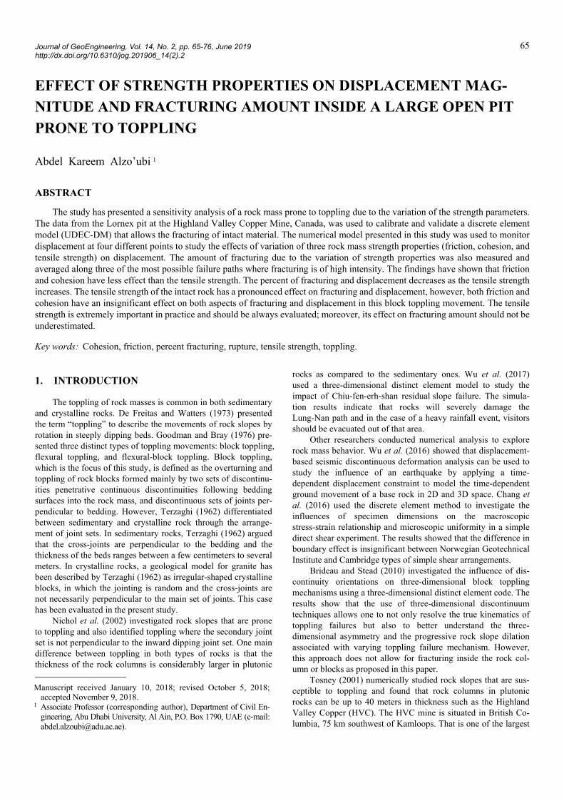
fracturing, Voronoi tessellation was used to generate flaws with a 1.4 m edge length inside the area that was susceptible to toppling. These flaws create random blocks surrounded by flaws. The im-plementation of flaws resulted in generating randomly polygonal blocks as shown in Fig. 7. The UDEC-DM (Alzo’ubi et al. 2007) approach allows for simulating flaws at different scales that rep-resent grain boundaries or larger discontinuities. The flaws inside the numerical model represent small joints, cracks, or any dis-continuous boundaries. However, their properties can be the same as the intact material ones.
The flaws were generated in the region that is susceptible to toppling and it was determined by using a preliminary conven-tional UDEC model similar to Tosney (2001)’s model. Figure 8 shows the conventional UDEC model and the displacement vec-tors which identify the region susceptible to toppling. The zone of movement included in this research were determined such that it includes all the blocks that have displacement greater than zero.
Fig. 7 The UDEC-DM showing the generated flaws and loca-tions of the slope-monitoring prisms, along with the two sets of joints
Fig. 8 Conventional UDEC model used to determine the area prone to toppling
8.1 Calibration of the Model
The numerical model was calibrated against the field defor-mation associated with the mining steps at the toe of the slope. The rock slope was monitored using SMP’s (Fig. 7). The mining- induced deformation captured by SMP number 413 was used to calibrate the model at two arbitrary stages. The rest of the data was calibrated along with the other three SMPs, which were used for validation of the results independently;
1. The normal and shear stiffness of the flaws (Voronoi flaws at the boundary of the blocks) were initially calculated by;
min
4
3n
K GK
Z
(2)
where Kn is normal stiffness; K is the bulk modulus; G is the shear modulus; Zmin is the smallest width of an adjoining zone in the normal direction.
2. Shear stiffness of the flaws (Voronoi flaws at the boundary of the blocks) was assumed equal to the normal stiffness ini-tially calculated in step 1.
3. Block numbers 1 through 8 were excavated (Fig. 6) and the displacement was recorded after reaching equilibrium. The excavation has been conducted step by step in the numerical simulations at the same sequence of the actual blasting and excavating in the mine.
4. Block numbers 9 through 13 were excavated (Fig. 6), step by step, and the total displacement was recorded after reaching equilibrium.
5. The total mining-induced displacement at the numerical model was compared with the total displacement observed at the field.
6. The shear stiffness of the flaws was changed and steps 2 ~ 5 were repeated until the gap between the calculated and ob-served displacement became as small as possible.
The displacement, velocity, and unbalanced forces of the model were monitored to guarantee the stability of the model as mining started at the toe. The numerical model produced a very good agreement between the calculated and observed displace-ment at the normal and shear stiffness values (Table 4).
At first, the model was brought to equilibrium under high strength properties, then the model was brought to equilibrium under realistic properties, and finally, the model was calibrated by simulating the mining pushbacks step by step. This modeling process was used to escape the initial unrealistic behavior of the numerical model. Figure 9 shows a comparison between the sim-ulation results and the actual displacement of the field. Figure 9 has indicated excellent results at this stage; therefore, the shear and normal stiffness were kept constant for the entire study. The displacement values were compared with the four SMP readings to identify any discrepancy between the field and the results of the numerical model.
In this analysis, local and global damping is necessary to keep the UDEC-DM model under control. This modeling method allows for the finite displacement and rotations of discrete deformable or rigid blocks, as well as for complete detachment.

AbdelKareem Alzo’ubi: Effect of Strength Properties on Displacement Magnitude and Fracturing Amount inside a Large Open Pit Prone to Toppling 71
Table 4 Normal and shear stiffness resulting from the calibra-tion process
RMR 76 Normal stiffness (GPa/m) Shear stiffness (GPa/m) 40 ~ 44 11 3.5 45 ~ 49 14 4.5 60 ~ 64 34 11 65 ~ 69 46 15
Fig. 9 Field displacement versus UDEC-DM results after cali-bration at blocks 8 and 13
The discrete element method calculation step alternates between application of a force-displacement law at the contacts and ap-plication of Newton’s second law at all blocks. Local and global damping is essential to keep the model under control.
In the discrete element method, a rock mass is represented as discrete blocks, and discontinuities are treated as interfaces between bodies. The contact displacements and forces at the in-terfaces are calculated by tracing the movements of the blocks. Applied loads or forces to a block system can cause disturbances that propagate and result in movements. The propagation speed in this dynamic process depends on the physical properties of the blocks and the contacts (Itasca 2016). Moreover, in UDEC-DM, a time-stepping algorithm is used to represent the dynamic be-havior of the model, and within a time-step, the velocities and accelerations are assumed to be constant. The maximum unbal-anced force was used to stop the model automatically, once the unbalanced force fell below 2 kN the model stopped. Moreover, the model displacement was monitored to guarantee equilibrium has been achieved. Once the displacement at the prisms reached a constant value (without changing) after excavating one block, the maximum displacement was recorded. It is not worthy to mention that the time-step has to be small enough to stop the transmission of disturbances between one block and its nearby blocks. More-over, the time-step constraint applies to both blocks and contacts in deformable blocks that are used in this model. The total num-ber of numerical time steps at the end of the simulation were 2,029,950 steps with a numerical time of 198.8 seconds.
8.2 The UDEC-DM Validation
After equilibrium, the displacement, movement mode, and fracturing throughout the model were monitored to assure the validity of the model after comparing those with field observa-tions at that mining step. The engineers did not detect a thor-oughgoing rupture surface in the south wall pit. The study has
compared the results of the numerical model and field in terms of movement mode, the displacement, and the differences between UDEC-DM and conventional UDEC. These steps were taken after calibration to ensure the validity of the model’s results. This increased the confidence in the model that was used to study the slope behavior under variation of the strength properties of the intact material.
8.2.1 Movement Mode
Three distinct movements were observed at the slope: sliding at the crest of the slope, normal toppling over most of the slope, and dilation and bulging at the toe. Figure 10 shows the slope after excavating the last block (block 15). The numerical model pro-duced identical movements to the ones observed in the field. The UDEC-DM replicated the progressive movement in the field due to the UDEC-DM ability to simulate rocks fracturing inside the slope. The simulation was able to reproduce the surface expres-sions observed at the Lornex southeast wall: normal scarp and sliding at the crest of the slope, consequent scarp in the middle, and dilation at the bottom as shown in Fig. 10. The inset in Fig. 10 provides a closer look at the movement mode at the crest. The formation of normal scarp is a fundamental characteristic of the block toppling movement due to rock blocks overturning.
The sliding along in dipping faults allowed the toppling of the rock blocks. Alzo’ubi et al. (2012) showed that this sliding is a fundamental aspect of toppling movement, which formed con-sequent scarps facing up the slope (Fig. 11). High amount of dilation and fracturing occurred at the toe of the slope as shown in Fig. 11. This movement aspect of the movement has been ob-served twice at the Lornex southeast and southwest walls (Alzo’ubi et al. 2012), Figs. 12 and 13 show the southeast top-pling movement at the pit, and the tension cracks and stress re-laxation at the southwest wall of the pit, respectively. No clear rupture surface was formed at the site although the toppling movement had occurred (Tosney 2001) and no catastrophic fail-ure was recorded. The UDEC-DM model showed that no con-tinuous rupture surface was formed.
Fig. 10 The movement mode at the Lornex southeast wall as
simulated by the UDEC-DM
Normal scarps formed at the crest of the slope
Obsequent scarps
Bulging
30 m

72 Journal of GeoEngineering, Vol. 14, No. 2, June 2019
Fig. 11 Plot of the numerical model, showing the rupturing on the slope
Fig. 12 Southeast wall: large-scale toppling failure (Brox and Newcomen 2003)
Fig. 13 Southwest wall: tension cracks and obsequent scarp formed at the site (Brox and Newcomen 2003)
The rock mass at the toe dilated with highly fractured mate-rial due to a high-stress concentration that resulted from rock columns toppling above that region. Tosney (2001) mentioned that loose material at the toe delayed the operation on several occasions during the mining. As the confinement was decreased by mining pushbacks, the stress concentration at the toe increased which caused extensive fracturing, fragmentation, and formation of loose material (Fig. 14). Cruden and Varnes (1996) described this type of movement at the toe as “flow”. The results show that the numerical model successfully simulated the movements de-tected in the field.
8.2.2 Magnitude of Displacement
The southeast wall suffered from meters of displacement and the engineers used four SMP’s to monitor that displacement. The history function in the program was utilized to monitor the displacement of the slope as blocks 1 to 15 were excavated. Fig-ure 15 shows the measured displacement at the field and the nu-merical model outcome for SMP#468. However, the simulated mining-induced deformations are in good concurrence with the field records. The displacement in the numerical model was asso-ciated with the excavation of the toe blocks, which were located adjacent to the slope.
Fig. 14 Dilation and loose rocks at the toe using RMR values in the UDEC-DM model
Fig. 15 Comparison between deformation of the field and the
UDEC-DM at SMP#468
0.00 50 100 150 200 250 300 350 400
Distance (m)
Dis
tan
ce (
m)
1625
1575
1525
1475
1425
1375
1325
1275

AbdelKareem Alzo’ubi: Effect of Strength Properties on Displacement Magnitude and Fracturing Amount inside a Large Open Pit Prone to Toppling 73
Similar results and a good agreement were found between the results at the location of SMP#454. The movement mode along with the deformation magnitude and trend confirmed the validity of the model. This warrants the use of this approach to understanding the fracturing pattern and the sensitivity of the model behavior to the variation of the strength parameters.
8.2.3 Deformation Comparison between Conventional UDEC and the UDEC-DM
Tosney et al. (2004) used the conventional UDEC to simu-late the Lornex southeast wall behavior. The results were used to compare them with the UDEC-DM. The comparison showed that UDEC-DM produced better results as compared to the conven-tional UDEC. Figures 16 and 17 present the results at the re-maining two prisms: SMP#413 and SMP#560, respectively. An improvement was achieved by using the UDEC-DM at the loca-tion of SMP#413 at blocks number 7, 8, 9, 10, 11, 12, and 13 whereas, at SMP#560, the heel of the slope, the UDEC-DM has shown far better agreement with the field records than the con-ventional UDEC starting from block 8 and beyond. These results might be attributed directly to the fracturing capabilities of the UDEC-DM that allowed the material to dilate within the slope and at the toe of the slope. This fracturing is not feasible in con-ventional UDEC, and dilation is limited and is much lower than what was observed in the field.
Fig. 16 Measured field displacements, simulated UDEC-DM, simulated UDEC displacements at SMP#413
Fig. 17 Field measurement of the UDEC-DM, and the UDEC displacements at SMP#560
Tosney et al. (2004) stated that the secondary joints were not detected in the fractured material at the toe of the slope. One pos-sible rationalization is that fracturing occurred throughout the intact material and not at the joints, which indicated the need of having a model with fracturing ability to simulate the behavior correctly. The current discrete element approach, UDEC-DM, has successfully modeled the dilation and fracturing at the toe of the Lornex southeast wall, captured the deformations associated with this fracturing and formed loose material at the open-pit mine toe. Therefore, this modeling approach could be useful in predicting the possibility of flow of the rock material or excessive defor-mation and dilation that might endanger a mining operation.
8.3 Sensitivity Analysis
The paper has presented the case history, calibration, and validation of the model by using different parameters presented in Tables 1 and 2. The properties have been kept constant throughout the analysis. The analysis showed that this approach is capable of handling the slope movement mode, and its dis-placement magnitude. The modeling approach has produced marginally better results as compared to conventional UDEC. The displacement magnitude and fracturing amount inside the slope have been used to study the effect of the variation of the strength parameters on the slope behavior. The properties of flaws inside the rock blocks represent the intact material proper-ties that show the sensitivity of the slope behavior.
8.3.1 Effect of Friction, Cohesion, and Tensile Strength on Displacement
To study the effect of the rock strength on the slope’s mag-nitude of displacement, one parameter has been varied and the other two parameters have been kept constant. The friction angle of the flaws was varied and cohesion and tensile strength were kept constant. At the first attempt, the friction angle of the flaws was increased in accordance with the values shown in Table 5. The simulation was conducted by increasing the friction angle by one degree for all geological units. For instance, the region that was classified as RMR76 = 40 has a friction angle of 29° and was increased to 34° gradually, one degree at a time. The value of the friction angle of all different layers has been changed at the same time.
Each simulation started from a new model at equilibrium state with different material properties and then excavation start-ed. After each increment, the slope behavior was monitored at each new friction angle in terms of rupture, movement mode, and displacement. Figure 18 shows the displacement at SMP#413 at the peak friction angle compared with the displacement at the lowest friction angle for all units. Figure 18 shows that friction angle increments of the intact material for each block did not change the displacement magnitude substantially.
Table 5 Mohr-Coulomb strength parameters used in the para-metric study
RMR 76 () C (MPa) 40 29 ~ 34 0.85 ~ 1.45 50 37 ~ 43 0.95 ~ 1.55 60 44 ~ 50 1.15 ~ 1.75 70 49 ~ 56 1.55 ~ 2.15 80 55 ~ 56 2.25 ~ 2.85

74 Journal of GeoEngineering, Vol. 14, No. 2, June 2019
Fig. 18 Displacement at SMP#413, = 34 versus = 29
The same steps were followed to investigate the effect of cohesion, which was increased incrementally for all geological units by 0.1 MPa (Table 5). At each cohesion increment, the ten-sile strength and friction angles were kept constant, and the value of the cohesion of all different layers has been changed at the same time. The cohesion increments showed the same results as the friction increments. The cohesion variation did not alter the deformation behavior or the movement patterns, i.e., the dis-placement magnitude of the models remain unchanged after they were compared to the results of the model with original cohesion values. According to this parametric study, the friction and cohe-sion of the intact material (flaws) have minimal effect on the displacement of toppling slope.
Moreover, the tensile strength was changed from 0.1 to 1 MPa in 0.1 MPa increments; while, the friction and tensile strength constant were kept constant. The tensile strength of the block materials produced a significant change in the magnitude of displacement. Alzo’ubi et al. (2010) showed that the tensile strength plays a fundamental role in governing slopes prone to toppling by using two examples: flexural toppling, and block-flexural toppling model with two sets of joints. Figure 19 presents the displacement at SMP#413 for two values of tensile strength 0.1 MPa and 1.0 MPa, along with the field mining- induced deformation. The mining-induced deformation in this model (t means tensile strength, t = 1.0 MPa) is much smaller as compared to the measured deformation at the low tensile strength model. However, the simulated deformation is much nearer to the field measurement at a tensile strength of 0.1 MPa.
Fig. 19 Deformation comparison at t = 0.1 MPa and t = 1.0
MPa at SMP#413
This analysis has included persistent joint only; however, non-persistent ones were encountered in the field as secondary set of joints. This non-persistency of joints might alter the state of stress and consequently affect the amount of deformation and the amount fracturing. Ladanyi and Archambault (1980) observed that non-persistent joints alter the state of stress near the joint tip and in the rock bridges. Similar results were also found by Alzo’ubi (2016). Increasing tensile strength reduces the displacement in four SMPs. The tensile strength of the material prevented tensile stresses from fracturing the rock material, which reduces the de-formation magnitudes as we will see in the coming sections.
8.3.2 Effect of Friction, Cohesion, and Tensile Strength on Fracturing
Three possible failure paths were selected, and the length of fractures was measured to investigate the amount of fracturing inside the slope under variation of the strength parameters. Figure 20 shows the selected three paths in the most extensive fracturing region of the slope; these paths were selected to pass through the most possible rupture surface inside the slope. The CAD program has been used to measure variation in the length of the fracture intersecting each of the three paths (AutoCAD 2016). The lengths were summed up to get the entire length of the fractures intersecting that specific path. The ratio between the entire lengths of fractures to the entire path length defines a parameter called Percent Fracturing (PF). This parameter is used in this paper to show the intensity of fracturing due to the variation of the three strength parameters. All models in this study reached an equilibrium state and fracturing was measured at that stage.
The fractured joints along the selected paths have been mapped, measured, and normalized to the entire length of the path to calculate a PF of 25.1%; when the original parameters were assigned to the model. The properties of this model are the starting values of the range shown in Table 5 and the tensile strength of the flaws was 0.1 MPa. This process was repeated for every model with a new strength value. The fracturing percentage was calculated and averaged along the three paths at the same numerical time as cohesion was varied using the values shown in Table 5. The measured PF due to cohesion variation ranged be-tween 24.8% and 25.1% for the entire range of cohesion values. This variation of fracturing, considering the errors that were in-volved in the measuring tools, is insignificant and very close to the PF observed in the original model (Fig. 21).
Fig. 20 The selected paths to measure the percentage of frac-
turing, tensile strength = 0.1 MPa
0.00 50 100 150 200 250 300 350 400
Distance (m)
Dis
tan
ce (
m)
1625
1575
1525
1475
1425
1375
1325
1275
29 34
Observed
AbdelKareem Alzo’ubi: Effect of Strength Properties on Displacement Magnitude and Fracturing Amount inside a Large Open Pit Prone to Toppling 75
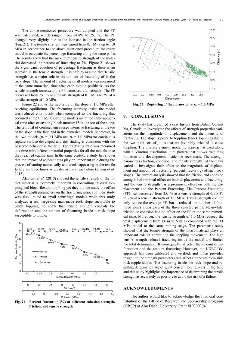
The above-mentioned procedure was adopted and the PF was calculated, which ranged from 24.8% to 25.1%. The PF changed very slightly due to the increase in the friction angle (Fig. 21). The tensile strength was varied from 0.1 MPa up to 1.0 MPa in accordance to the above-mentioned procedure for every model to calculate the percentage fracturing along the same paths. The results show that the maximum tensile strength of the mate-rial decreased the percent of fracturing to 7%. Figure 21 shows the significant reduction of percentage fracturing as there is an increase in the tensile strength. It is safe to assume that tensile strength has a major role in the amount of fracturing of in the rock slope. The amount of fracturing in all models was measured at the same numerical time after each mining pushback. As the tensile strength increased, the PF decreased dramatically. The PF decreased from 25.1% at a tensile strength of 0.1 MPa to 7% at a tensile strength of 1.0 MPa.
Figure 22 shows the fracturing of the slope at 1.0 MPa after reaching equilibrium. The fracturing intensity inside the model was reduced enormously when compared to the fracturing that occurred at the 0.1 MPa. Both the models are at the same numeri-cal time after excavating block number 15 at the toe of the slope. The removal of confinement caused intensive fracturing at the toe of the slope in the field and in the numerical models. Moreover, in the two models (t = 0.1 MPa and t = 1.0 MPa) no continuous rupture surface developed and this finding is consistent with the observed behavior in the field. The fracturing ratio was measured at a time with different material properties for all the models once they reached equilibrium. In the same context, a study has shown that the impact of adjacent cuts play an important role during the process of cutting numerically and cracks appearing in the tensile failure are three times as greater as the shear failure (Zhang et al. 2015).
Alzo’ubi et al. (2010) showed the tensile strength of the in-tact material is extremely important in controlling flexural top-pling and block-flexural toppling yet they did not study the effect of the strength parameters on the fracturing ratio, and their study was also limited to small centrifugal models while this study analyzed a real large-size man-made rock slope suciptable to block toppling, to show that tensile strength controls the deformation and the amount of fracturing inside a rock slope susceptible to topple.
Fig. 21 Percent fracturing (%) at different cohesion strength,
friction, and tensile strength
Fig. 22 Rupturing of the Lornex pit at t = 1.0 MPa
9. CONCLUSIONS
The study has presented a case history from British Colum-bia, Canada, to investigate the effects of strength properties vari-ations on the magnitude of displacement and the intensity of fracturing. The slope is prone to toppling (block toppling) due to the two main sets of joints that are favorably oriented to cause toppling. The discrete element modeling approach is used along with a Voronoi tessellation joint pattern that allows fracturing initiation and development inside the rock mass. The strength parameters (friction, cohesion, and tensile strength) of the flaws varied to investigate their effect on the magnitude of displace-ment and amount of fracturing (percent fracturing) of such rock slopes. The current analysis showed that the friction and cohesion strength had minimal effect on both displacement and fracturing, and the tensile strength has a prominent effect on both the dis-placement and the Percent Fracturing. The Percent Fracturing (PF) was decreased from 25.1% at a tensile strength of 0.1 MPa to 7% at a tensile strength of 1.0 MPa. Tensile strength did not only reduce the average PF, but it reduced the number of frac-tured joints along each of the three selected paths. Meanwhile, friction or cohesion had no effect on the PF at the same numeri-cal time. Moreover, the tensile strength of 1.0 MPa reduced the total displacement from 14 m to 6 m as compared with the 0.1 MPa model at the same mining stage. The parametric study showed that the tensile strength of the intact material plays an important role in controlling the toppling movement. The high tensile strength reduced fracturing inside the model and limited the total deformation. It consequently affected the amount of de-formation and the amount fracturing. However, the UDEC-DM approach has been calibrated and verified, and it has provided insight on the strength parameters that affect composite rock-slide rock-topple slopes. The fracturing inside the rock slope and re-sulting deformation are of great concern to engineers in the field and this study highlights the importance of determining the tensile strength as accurately as possible to avoid the risk of a failure.
ACKNOWLEDGMENTS
The author would like to acknowledge the financial con-tribution of the Office of Research and Sponsorship programs (ORSP) at Abu Dhabi University Grant #19300304.
Tensile
Friction
Cohesion
Tensile Strength (MPa)
Friction ()
Cohesion (MPa)
Pe
rce
net f
ract
urin
g (%
)

76 Journal of GeoEngineering, Vol. 14, No. 2, June 2019
CONFLICT OF INTEREST
The research has no conflict of interest and it is partially funded through the ORSP at Abu Dhabi University.
NOTATIONS
: Inclination of the slope face (°) : Friction angle (°) : Dip of the main set of joints (°) Kn : Normal stiffness (GPa/m) K : Bulk modulus (GPa) G : Shear modulus (GPa) Zmin : Smallest width of an adjoining zone in the normal
direction (m) UCS : Unconfined Compressive Strength (MPa) C : cohesion (kPa) t : Tensile strength (MPa)
REFERENCES
Alzo’ubi, A.K., Martin, C.D., and Cruden, D.M. (2007). “A discrete element damage model for rock slopes.” Proceedings of 1st Canada-US Rock Mechanics Symposium, American Rock Me-chanics Association, Vancouver, Canada, 503-510. https://doi.org/10.1201/noe0415444019-c62
Alzo’ubi, A.K. (2009). The Effect of Tensile Strength on the Stabil-ity of Rock Slopes. Ph.D. Dissertation, Department of Civil and Environmental Engineering, University of Alberta, Edmonton, Alberta, Canada. https://doi.org/10.7939/R32J68F7S
Alzo’ubi, A.K., Martin, C.D., and Cruden, D.M. (2010). “Influence of tensile strength on toppling failure in centrifuge tests.” Inter-national Journal of Rock Mechanics and Mining Sciences, 47, 974-892. https://doi.org/10.1016/j.ijrmms.2010.05.011
Alzo’ubi, A.K. (2012). “Modeling of rocks under direct shear load-ing by using discrete element method.” AHU Journal of Engi-neering and Applied Science, 4(2), 5-20.
Alzo’ubi, A.K., Martin, C.D., and Cruden, D.M. (2012). “Effect of mining on deformation patterns in a large open pit rock slope.” Rock Engineering for Natural Resources, 229-236.
Alzo’ubi, A.K. (2016). “Modeling yield propagation of jointed syn-thetic rock.” Rock Mechanics and Rock Engineering: From the Past to the Future, 113, Cappadocia, Turkey, 113-118. https://doi.org/10.1201/9781315388502-17
AutoCAD (2016). Computer Aided Design Software, Version 20.1, Autodesk Company.
Brideau, M.A. and Stead, D. (2010). “Controls on block toppling using a three-dimensional distinct element approach.” Rock Mechanics and Rock Engineering, 43(3), 241-260. https://doi.org/10.1007/s00603-009-0052-2
Brown, E.T. and Hoek, E. (1988). “Discussion of ‘Determination of the shear failure envelope in rock masses.’ by Roberto Ucar (March, 1986, Vol. 112, No. 3).” Journal of Geotechnical En-gineering, ASCE, 114, 371-373. https://doi.org/10.1061/(ASCE)0733-9410(1988)114:3(371.2)
Brox, D. and Newcomen, W. (2003). Utilizing Strain Criteria to Predict Highwall Stability Performance ISRM 2003— Technology Roadmap for Rock Mechanics. South African Insti-tute of Mining and Metallurgy.
Chang, W.J., Phantachang, T., and Ieong, W.M. (2016). “Evaluation of size and boundary effects in simple shear tests with distinct element modeling.” Journal of GeoEngineering, TGS, 11(3),
133-142. https://doi.org/10.6310/jog.2016.11(3).3 Chen, Z., Gong, W., Ma, G., Wang, J., He, L., Xing, Y., and
Xing, J. (2015). “Comparisons between centrifuge and numeri-cal modeling results for slope toppling failure.” Science China Technological Sciences, 58(9), 1497-508. https://doi.org/10.1007/s11431-015-5889-x
Cruden, D.M. and Varnes, D.J. (1996). “Landslide types and pro-cesses.” Landslides and Engineering Practice, 24, 20-47.
De Freitas M.H. and Watters, R.J. (1973). “Some field examples of toppling failure.” Geotechnique, 23, 495-513. https://doi.org/10.1680/geot.1973.23.4.495
Goodman, R.E. and Bray, J.W. (1976). “Toppling of rock slopes.” Rock Engineering for Foundations and Slopes, ASCE, 201-234.
Goodman, R.E. (1989). Introduction to Rock Mechanics. New York: Wiley.
Itasca Consulting Group, Inc. (2016). Udec-Universal Distinct Ele-ment Code, Version 6.0, Minneapolis.
Ladanyi, B. and Archambault, G. (1980). “Direct and indirect deter-mination of shear strength of rock mass.” Proceedings of Socie-ty of Mining Engineers of AIME, AIME Annual Meeting, Las Vegas, Nevada, USA, Preprint No. 80-25, 16 p.
Newcomen, H.W., Murray, C., and Shwydiuk, L. (2003). “Monitor-ing pit wall deformations in real time at Highland Valley Cop-per.” InCAMI Conference, Calgary, 8-10.
Nichol, S.L., Hungr, O., and Evans, S.G. (2002). “Large-scale brittle and ductile toppling of rock slopes.” Canadian Geotechnical Journal, 39, 773-788. https://doi.org/10.1139/t02-027
Terzaghi, K. (1962). “Stability of steep slopes on hard unweathered rock.” Geotechnique, 12, 251-270. https://doi.org/10.1680/geot.1962.12.4.251
Tosney, J.R. (2001). “A design approach for large scale rock slopes.” Unpublished Master of Science Thesis, University of Sas-katchewan.
Tosney, J.R., Milne, D., Chance, A.V., and Amon, F. (2004). “Veri-fication of a large-scale slope instability mechanism at Highland Valley Copper.” International Journal of Surface Mining, Rec-lamation and Environment, 18, 273-288. https://doi.org/10.1080/1389526042000263324
Varnes, D.J. (1958). “Landslide types and processes.” Landslides and Engineering Practice, 29, 20-45.
Waldner, M., Smith, G., and Willis, R. (1976). Lornex. In Porphyry Deposits of the Canadian Cordillera 15.
Wu, J., Do, T., Chen, C., and Wang, G. (2016). “New geometric restriction for the displacement—Constraint points in discon-tinuous deformation analysis.” International Journal of Geo-mechanics, ASCE, 17(5), 1-18. https://doi.org/10.1061/(ASCE)GM.1943-5622.0000648
Wu, J., Lin, W., and Hu, H. (2017). “Assessing the impacts of a large slope failure using 3DEC: The Chiu-fen-erh-shan residual slope.” Computers and Geotechnics. 88, 32-45. https://doi.org/10.1016/j.compgeo.2017.03.002
Zhang, Q.Q., Han, Z.N., Ning, S.H., Liu, Q.Z., and Guo, R.W. (2015). “Numerical simulation of rock cutting in different cut-ting mode using the discrete element method.” Journal of Geo- Engineering, TGS, 10, 35-43. http://dx.doi.org/10.6310/jog.2015.10(2).1
Zheng, Y., Chen, C., Liu, T., Xia, K., and Liu, X. (2017). “Stability analysis of rock slopes against sliding or flexural-toppling fail-ure.” Bulletin of Engineering Geology and the Environment, 1-21. https://doi.org/10.1007/s10064-017-1062-z
Zheng, Y., Chen, C., Liu, T., Zhang, H., Xia, K., and Liu, F. (2018). “Study on the mechanisms of flexural toppling failure in anti- inclined rock slopes using numerical and limit equilibrium models.” Engineering Geology, 237, 116-128. https://doi.org/10.1016/j.enggeo.2018.02.006