effect of manufacturer's joint fastening techniques on compression strength of corrugated
TRANSCRIPT
Effect of Manufacturers Joint Fastening Techniques on Compression Strength of
Corrugated Fiberboard Boxes
J SINGH1 A ATTEMA2 E OLSEN3 and K VORST3
1Associate Professor Industrial Technology Cal Poly State University San Luis Obispo CA
2Research Assistant Industrial Technology Cal Poly State University San Luis Obispo CA
3Assistant Professor Industrial Technology Cal Poly State University San Luis Obispo CA
ABSTRACT A flat piece of corrugated fiberboard which has been cut slotted and scored is often referred to as a box blank For several box styles in order to convert the box blank into a box its two ends must be fastened together with tape staples or adhesives such as water soluble glues The location at which the two ends meet is known as the manushyfacturers joint There are several variations within the three fastening techniques mentioned with most corrugated box manufacturers followshying their own protocols for fastening the manufacturers joints This study explored the compression and tensile strengths of RSC style corshyrugated boxes based on adhesive (glue) coverage three different types of tapes (acrylic paper and reinforced paper) and application anshygie of staples The fabricated boxes were also tested for compression strength and deflection Test data (N = 10) was collected for each deshypendent variable of peak force deflection at peak force and tensile strength using the analysis of variance procedure with a Turkey probashybility distribution at a 005 critical limit The results suggest an overall higher tensile strength for glue than the other fastening techniques evaluated (P lt 005) with no significant difference (P gt 005) for peak force or deflection at peak force for all glued stapled or taped treatshyments
10 INTRODUCTION
DUE to its high strength to low weight ratio corrugated packaging is poised as the leading choice for transport packaging in the United
States By some estimates corrugated packaging is used to package apshy
Author to whom correspondence should be addressed Email jasinghcalpolyedu
Journal of Applied Packaging Research Vol 3 No4-October 2009 233
1557-72440904233-11 copy 2009 DEStech Publications Inc
234
J SINGH A ATTEMA E OLSEN and K VORST
proximately 90 of all products for retail distribution in the United States [1] The popularity of corrugated packaging also stems from the fact that it is practical useful economical renewable and recyclable [1] It is also a substrate that can be custom designed and provides excellent merchandising appeal through printing on box panels Twede [2] acshycounted that 80 of the $46 billion worth of paper based packaging used is corrugated fiberboard shipping containers
Corrugated fiberboard is a paper-based material consisting of a fluted containerboard sheet and at least one flat linerboard It is widely used in the manufacture of corrugated boxes and shipping containers Throughshyout the journey of a containerboard from the paper mills to box plants which include the corrugated box plants and sheet plants close quality control is provided to material properties such as basis weight caliper burst strength water absorption porosity to air and smoothness Variashytions in material properties can affect the strength and performance of corrugated boxes
Boxes from the corrugated fiberboard sheets can be formed in the same plant as the corrugator or alternatively sheets of corrugated fibershyboard can be shipped to a sheet plant for conversion into boxes At both these facilities the corrugated board is creased or scored to provide conshytrolled bending of the board Slots are typically cut to provide flaps for boxes The Regular Slotted Container (RSC FEFCO 0201) is the most common style of corrugated box used in the industry [1] All flaps for this style of construction are the same length and the outer (major) flaps meet at the center of the box Figure 1 illustrates a box blank for a RSC style box as well as an assembled box
At the conversion plants the two ends ofthe box blank are fastened toshygether with tape staples or adhesives (glue) for conversion to a box The location at which these two ends meet is known as the manufacturers joint It may be noted that not all corrugated containers such as bliss
_______________J _ I It I I
Score lines I
ManUfaClUrrfS Joint I Slot I-- ----- --- -- ----11-3----- ---shyFigure 1 Box Blank ShOWing Score Lines Slots amp Manufacturers Joint and Assembled RSC
235 Effect of Manufacturers Joint Fastening Techniques
GlucdJoint Glued Joint Tllpt-ltl Joint (inside of box) (olJtside of box) (outSide of box)
Stitched Joint Stitched Joint (inside of bolt) (ouL~ide of box)
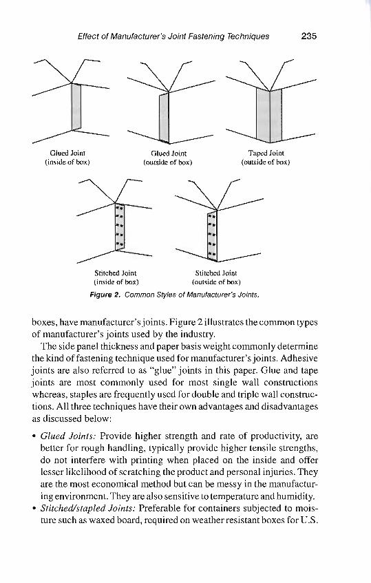
Figure 2 Common Styles of Manufacturers Joints
boxes have manufacturers joints Figure 2 illustrates the common types of manufacturers joints used by the industry
The side panel thickness and paper basis weight commonly determine the kind of fastening technique used for manufacturers joints Adhesive joints are also referred to as glue joints in this paper Glue and tape joints are most commonly used for most single wall constructions whereas staples are frequently used for double and triple wall construcshytions All three techniques have their own advantages and disadvantages as discussed below
bull Glued Joints Provide higher strength and rate of productivity are better for rough handling typically provide higher tensile strengths do not interfere with printing when placed on the inside and offer lesser likelihood of scratching the product and personal injuries They are the most economical method but can be messy in the manufacturshying environment They are also sensitive to temperature and humidity
bull Stitchedstapled Joints Preferable for containers subjected to moisshyture such as waxed board required on weather resistant boxes for US
236 J SINGH A ATTEMA E OLSEN and K VORST
government objectionable when used with food products may intershyfere with printing layouts may scratch a finely finished products surshyface and may cause wrinkles and permit the comer of the box to fold on the line of stitches
bull Taped foints They do 110t require a tab and hence use lesser material and by providing more efficient layouts decrease scrap knocked down boxes lie flatter in tied bundles the inside of the box is smoother provides convenient means of easily opening the box intershyferes with some print layouts and is more expensive than glue A simshyple shift from glue to taped boxes reduces corrugated material use but can result in additional costs
11 Manufacturers Joint Related Regulations
There are several regulations related to corrugated products such as those set by carriers (rail and truck) US government (DOT FDA USDA and EPA) and the Council of State Governments which provide guidelines regarding corrugated container construction [12] More clearly defined specifications which can be considered as industry stanshydards for corrugated materials are provided by the Fiber Box Associashytion (FBA) or the Association of Independent Corrugators (AICC) and machinery and fabrication equipment guidelines and standards can be obtained from the Packaging Machinery Manufacturers Institute (PMMI) [345] Although the tolerances provided by FBA and PMMI are voluntary most corrugated manufacturing companies and many corshyrugated users consider these as specifications to be used when manufacturing or specifying most corrugated packaging
The carrier rules provide the following guidelines for manufacturers joints [1]
Single and Double Wall Fiberboard Constructions Boxes must have manufacturers joints formed by lapping the sides of
the box forming the joint not less than 318 cm where the 318 cm is the actual overlapping or mating area (Figure 3) As regards to fastening techniques the following guidelines are provided
bull Metal staples or stitches generally spaced not more than 635 cm apart except when weight of box and contents is 635 kg or moreshyspaced not more than 254 cm apart
237 Effect of Manufacturers Joint Fastening Techniques
j
----1
I
bull~bullbullbull
Actual overlapping or mating area ~ 318 cm
Figure 3 Carrier Rule for Manufacturers Edge Overlap
bull Glue gluing the entire area ofcontact with a water-resistant adhesive bull Taping (butted joints) sealing strips firmly glued to the box and exshy
tending the entire length of the joint Sealing strips must be of suffishycient strength that rupture of the joint occurs with fiber failure of one or more of the facings
Triple Wall Fiberboard Construction Boxes must have the manufacturers joint formed by one of the folshy
lowing methods
1 By lapping the sides of the box forming the joint not less than 508 cm and fastening the joint with metal staples or stitches spaced not more than 254 cm apart Both sides of the joint must be crush-rolled in the area of contact before stapling or stitching
2 By lapping the sides of the box forming the joint not less than 762 cm The joint must be firmly glued with 100 glue coverage in the area of contact with glue or adhesive which cannot be dissolved in water after the film application has been dried under pressure
Corrugated shippers are designed to overcome the distribution envishyronment hazards so that the products they carry reach the consumers inshytact and ready for use The transportation and warehousing hazards faced commonly by corrugated shippers include compression shock vibration temperature creep and humidity among others Most material (containerboard) and corrugated package testing procedures are proshyvided by the Technical Association of the Pulp and Paper Industry
238 J SINGH A ATTEMA E OLSEN and K VORST
(TAPPI) and American Society for Testing and Materials (ASTM) [6789]
When a shipping container is dropped during handling or compressed during stacking its manufacturers joint is subjected to stresses along with all other edges The TAPPI Test Method T 813 om-04 (Tensile Test for the Manufacturers Joint of Fiberboard Shipping Containers Test Method) helps determine the strength of the manufacturers joint of commercially made corrugated and solid fiberboard shipping containers and is applicable to taped stitched or glued joints which may also be used to evaluate laboratory fabricated joints similar to commercially made joints [6] ASTM D 642 (Standard Test Method for Determining Compressive Resistance ofShipping Containers Components and Unit Loads) is commonly used for measuring the ability ofthe container to reshysist external compressive loads applied to its faces to diagonally opposite edges or to comers [7]
At present there is no data available to demonstrate the effect ofvariashytions in the prescribed methods ofjoining the manufacturers edge as reshylated to the compression or the tensile strengths of corrugated boxes
The two objectives of this study were to
1 Compare the strength ofvarious methods used to fasten the manufacshyturing joint in RSC style boxes
2 Evaluate the affect of manufacturers joint fastening methods with respect to box compression strength and deflection
20 SURVEY OF INDUSTRY PRACTICES
Before initiating the experimental study a survey was conducted tarshygeting the manufacturers of corrugated boxes with regards to the comshymon practices used to form the manufacturers joint Responses were reshyceived from ten leading corrugated packaging manufacturers It was found that most manufacturers did not agree on the same technique Based on their operational capabilities and customer orders most follow their own protocols for fastening the manufacturers edge The followshying were some key findings from this survey
bull 90 used glue and 10 used staples bull 80 made internal manufacturers joints for 75 or above of their
production
Effect of Manufacturers Joint Fastening Techniques 239
bull 80 made external manufacturers joints for 25 or below of their production
bull 90 had at least 35 cm overlappingmating between the manufacshyturers joint and the panel
bull Of the manufacturers using staples only 333 used 254 cm spacing between staples Others used 381 cm to 508 cm as the spacing with one manufacturer using a double stitch start and then a spacing of 254 cm between adjacent staples
bull 556 of all users that stapled the manufacturer joint used a 45deg angle ofapplication followed by 222 ofusers who applied horizontal stashyples along the depth of the box
bull 70 of the manufacturers that used glue had at least 75 glue covershyage between the manufacturers joint and the panel 30 used 50 or less glue coverage
bull Of the manufacturers using glue 70 applied the glue using one or more vertical lines along the depth of the box
bull 89 of the manufacturers that used tape preferred reinforced paper tape along 100 of the depth of the box
30 MATERIALS AND METHODS
31 Manufacturer Joint Tensile Testing
The TAPPI test standard T 813 om-04 (Tensile Test for the Manufacshyturers Joint of Fiberboard Shipping Containers Test Method) was used to compare the performance of various fastening methods for manufacshyturers joints This test gives an indication of the ability of the joint to withstand rough handling without failure to the extent that failure is reshylated to the tensile strength of the joint itself [6] The initial jaw span for the tensile tester was set at 180 plusmn 5 mm and the rate of separation used was 25 plusmn 5 mmmin A Testometric tensile tester Model M350-5kN (Testometric Materials Testing Machines Company Lancashire United Kingdom) was used for all tests C-flute corrugated fiberboard was used with a basis weight of 2011520 kg929 sq m (443444lb1000 sq ft) a bursting strength of 125 Ncm2 and an edge crush test (ECT) of79 Ncm
Figure 4 indicates the location of the test samples obtained as related to the corrugated container
Tensile test strips were prepared in accordance to TAPPI T 813 om-04
240 J SINGH A ATIEMA E OLSEN and K VORST
Figure 4 Tensile Test Specimen Location
(Figure 5) The length of all samples was 200 mm Glued and taped manshyufacturer s joints used a width was 25 plusmn05 mm with stapled joints havshying a 38 plusmn05 mm in accordance with the standard The distance between the outer edge of the staples and the corresponding outer edge of the joint was 635 mm and only one staple was included per sample
Table 1 provides details of materials used to fasten the manufacturers joint All materials were procured from Uline Shipping Supplies (Waukegan IL USA)
For the glue joint 25 50 and 75 percent of the area on the manufacshyturers joint tab was covered with hot melt glue For the stapled joints the angles of staple applications were varied between 0 1530 and 45 degrees along the depth direction Ten samples for each variable were
i
IltE~S------ 2mmm ----loo ~---- l00nm ----)1
2Snnn OLUED JOINT
A ~I 1)8 mm
1lt gt1
STAPLED JOINT
Figure 5 Tensile Test Samples for Glued Taped and Stapled Joints
Effect of Manufacturers Joint Fastening Techniques 241
Table 1 Materials used for Fastening the Manufacturers Joints
Model Material Supplier No Description
Reinforced Uline 8-2350 76 cm wide Kraft paper reinforced paper tape with fiberglass yarn water activated
2 Paper tape Uline 8-9682 51 cm wide pressure sensitive 3 Acrylic tape Uline 8-472 51 cm wide solvent acrylic adhesive 4 Glue Uline 8-509 13 cm diameter hot melt glue 5 8taples Uline 8-1396 32 cm crown width 19 cm leg length
tested after conditioning for 24 hours at 23degC and 50 relative humidity in accordance with ambient conditions as described in ASTM D4332 [8]
32 Box Compression Strength Testing
The ASTM D 642 (Standard Test Method for Determining Compresshysive Resistance of Shipping Containers Components and Unit Loads) was used to test the compression strength [7] The procedure is comshymonly used for measuring the ability of the container to resist external compressive loads applied to its faces to diagonally opposite edges or to comers This test method is also used to compare the characteristics of a given design ofcontainer with a standard or to compare the charactershyistics of containers differing in construction This test method is related to TAPPI T 804 om-02 [9] The tests were conducted using a fixed platen arrangement on a Lansmont compression tester Model 152-30K (Lansmont Corporation Monterey CA USA) with a platen speed of 13 emminute and a pre-load of 2268 kg for zero-deflection in accorshydance with the standard
The same materials and joining methods as described in 31 were used for box compression testing The spacing between the staples for all anshygles was maintained at 508 em All boxes used for this study were regushylar slotted containers (RSC) style with dimensions of 508 cm x 406 cm x 254 cm and having a 38 cm wide manufacturers joint All corrugated box samples used for this study were created using ArtiosCAD software and the Premium Line 1930 model of the Kongsberg table (Esko Graphics Ludlow Massachusetts USA) Five box samples for each variable were tested after pre-conditioning for 24 hours at 50 relative humidity and 23dege
242 J SINGH A ATTEMA E OLSEN and K VORST
40 DATA AND RESULTS
Test data was collected for each dependent variable peak force deshyflection at peak force and tensile strength on ten samples of eachjoining method A total of 300 observations were used for this study The test data were compared for the three dependent variables using one way analysis of variance (ANOVA) with a Tukey post-hoc test A famshyily-wise error rate ofp = 005 was use to determine significance Table 2 provides a summary of the test data
41 Peak Force
The data showed little difference among the fastener technologies with respect to peak force capability None of the general categories of glue staple or tape were consistently higher or lower than another The overall ANOVA was significant at a 005 level Variability was obshyserved within the fastener technologies with a 45 degree stapling having particularly low values and reinforced tape having particularly high valshyues (Table 3) Overall glue coverage did not affect the peak force perforshymance significantly (P gt 005) indicating that 25 percent glue coverage was as effective as 75 percent Similarly no significant difference was found between tape systems (Pgt 005) Table 3 indicates the 95 percent confidence intervals for each fastening system
42 Deflection at Peak Force
All tape systems used in this study allowed significantly more deshyflection than the other general categories of fasteners (P lt 005) Tape systems deflected an average of 042 em while the other fasteners deshyflected and average of only 028 em Tape systems also exhibit signifishycantly higher coefficients of variation than either of the other general joining methods (Table 2) No significant differences were found beshytween glued or stapled units with respect to means or coefficients of variation Table 4 shows the 95 percent confidence intervals for each technology
43 Tensile Strength
All glue coverages had significantly higher tensile strengths than any
Join
ing
Me
tho
d
Glu
e 2
5
Glu
e 50
Glu
e 75
Sta
ple
0deg
Sta
ple
15deg
Sta
ple
30deg
Sta
ple
45deg
Acr
ylic
P
aper
R
einf
orce
d P
aper
Co
eff
lcie
nt
of V
aria
tion
Sp
eci
me
n W
idth
(m
m)
25
38
25
Tabl
e 2
Te
nsile
Tes
t Dat
a S
umm
ary
Pea
k F
orce
(N
) D
efle
ctio
n a
t P
eak
For
ce
(em
)
Mea
n C
ofV
Mea
n C
ofV
Glu
ed
Jo
ints
1857
1
79
4
1820
31
3
3
27
029
2 0
287
027
7
74
7
3
29
Sta
ple
d J
oin
ts
18
14
17
83
1882
17
05
53
5
9
34
5
4
027
7 0
27
7
027
2 0
287
80
5
2
63
6
0
Tap
ed J
oin
ts
1826
19
23
1810
61
6
5
114
043
2 0
427
040
1
311
341
380
Ten
sile
Str
en
gth
(k
Nm
)
Mea
n C
o
f V
154
2 9
2
188
0 4
7
211
6 4
4
198
14
2
2
04
11
0
2
13
73
2
58
62
46
8
114
717
5
7
668
7
3
It1 - 0 ~
0 ~
t poundit
0 eshy ~
en
c
0 Smiddot - ~ en til Smiddot
lQ
()l
0 shy 0
t
CD
en
I)
jgt
(
)
244 J SINGH A ATTEMA E OLSEN and K VORST
Table 3 Peak Force (N) 95 Confidence Intervals by Joining Method
Level Mean Std Dev
glue 25 1857 58 glue 50 1794 59 glue 75 1820 49
staple 0 1814 97 staple 15 1783 105 staple 30 1882 64 staple 45 1705 92
tape acrylic 1826 112 tape reinforced 1923 125 tape unreinforced 1810 206
Pooled Std Dev = 106
ofthe other fasteners with each increase in glue coverage having signifishycantly betterperformance (P gt 005) The average glue perfonnance was 185 kNm The stapled samples had the lowest perfonnance with an avshyerage tensile strength of 22 kNlm and no significant affect from staple angle The tape systems were stronger than the stapled samples with an average of 53 kNm Acrylic tape was significantly weaker than the other tape systems Using reinforced tape did not significantly improve tensile strength Table 5 shows the 95 percent confidence intervals for each technology
Table 4 Deflection at Peak Force (em) 95 Confidence Intervals by Joining Method
Level Mean Std Dev
glue 25 0292 0022 glue 50 0287 0021 glue 75 0277 0008
staple 0 0277 0022 staple 15 0277 0014 staple 30 0272 0017 staple 45 0287 0017
tape acrylic 0432 0134 tape reinforced 0427 0146 tape unreinforced 0401 0152
Pooled Std Dev = OOBO
245 Effect of Manufacturers Joint Fastening Techniques
Table 5 Tensile Strength (kNm) 95 Confidence Intervals by Joining Method
Level Mean Std Dev
glue 25 1542 142 glue 50 1880 089 glue 75 2116 093
staple 0 198 028 staple 15 204 022 staple 30 213 016 staple 45 258 016
tape acrylic 468 053 tape reinforced 717 041 tape unreinforced 668 049
Pooled Std Dev = 0675
50 CONCLUSION
The results of this study showed
1 Superior strength for tensile load to failure and breaking load for glued joints followed by stapled and taped joints
2 Reinforced taped joints showed the highest box compression strength followed by glued joints covering 25 of the overlap or mating area
25 ----------------------------shy
20 +1-------------------------1
~ g 15 I
1il c l
~101
~
ttl
5 +1--------------
() ( L I J j l II i
~ t) ~ ~ raquo ~ltfA
~amp~
0( clf- ~is( ~(l is~
~
ltI
J i- ~o ~Jgt -~ ~~ ~o$gtltl ~ ~ ~ltf qlt 0-gt~ ampraquo( amp-gt~
~ltf
$
Figure 6 Breaking Load (kNlm) Comparison for all Sample Types
246 J SINGH A ATTEMA E OLSEN and K VORST
050
045
040
035
030 ~ 025 ~
r010 8
015
010
005
000
_Porce ((g) -+-Deneliotl (em)
Figure 7 Compression Strength of Boxes with Different Types of Manufacturer Joints
and stapled joints applied at 30 degrees offset from the direction of depth of the box
3 This study suggests that boxes with glued manufacturers joints can offer better containment during shipping and handling
4 Caution should be exercised when relying on taped joints for deflecshytion performance
REFERENCES
I International Corrugated Packaging Foundation Corrugated Curricula-Course Materials on Corrugated Packaging httpwwwicpfboxorgl accessed February 4 2009
2 Twede D and S Selke Cartons Crates and Corrugated Board Handbook of Paper and Wood Packaging Technology ISBN No 1-932078-42-8 DEStech Publications Inc Lancasshyter PA USA 2005
3 Fiber Box Association 25 Nonhwest Point Blvd Suite 510 Elk Grove Village IL 60007 USA httpwwwfibreboxorgl accessed February 4 2009
4 Association of Independent Corrugators PO Box 25708 Alexandria VA 22313 USA hllpwwwaiccboxorgl accessed February 4 2009
5 Packaging Machinery Manufacturers Association 4350 N Fairfax Dr Suite 600 Arlington VA 22203 USA hllpwwwpmmiorg accessed February 4 2009
6 T 813 om-04 Tensile Test for the Manufacturers Joint of Fiberboard Shipping Containers 2006-2007 TAPPI Test Methods Technical Association of the Pulp and Paper Industry South Norcross GA 30092
7 ASTM 0642 Standard Tes Mehod for Deermining Compressive Resisance of Shipping
247 Effect of Manufacturers Joint Fastening Techniques
Containers Components and Unit Loads Vol 1510 American Society ofTesting and Mateshyrials West Conshohocken PA USA 2007
8 ASTM D4332-0l(2006) Standard Practice for Conditioning Containers Packages or Packshyaging Components for Testing Vol 1510 American Society of Testing and Materials West Conshohocken PA USA 2007
9 T 804 om-06 Compression Test ofFiberboard Shipping Containers 2006-2007 TAPPI Test Methods Technical Association of the Pulp and Paper Industry South Norcross GA 30092

234
J SINGH A ATTEMA E OLSEN and K VORST
proximately 90 of all products for retail distribution in the United States [1] The popularity of corrugated packaging also stems from the fact that it is practical useful economical renewable and recyclable [1] It is also a substrate that can be custom designed and provides excellent merchandising appeal through printing on box panels Twede [2] acshycounted that 80 of the $46 billion worth of paper based packaging used is corrugated fiberboard shipping containers
Corrugated fiberboard is a paper-based material consisting of a fluted containerboard sheet and at least one flat linerboard It is widely used in the manufacture of corrugated boxes and shipping containers Throughshyout the journey of a containerboard from the paper mills to box plants which include the corrugated box plants and sheet plants close quality control is provided to material properties such as basis weight caliper burst strength water absorption porosity to air and smoothness Variashytions in material properties can affect the strength and performance of corrugated boxes
Boxes from the corrugated fiberboard sheets can be formed in the same plant as the corrugator or alternatively sheets of corrugated fibershyboard can be shipped to a sheet plant for conversion into boxes At both these facilities the corrugated board is creased or scored to provide conshytrolled bending of the board Slots are typically cut to provide flaps for boxes The Regular Slotted Container (RSC FEFCO 0201) is the most common style of corrugated box used in the industry [1] All flaps for this style of construction are the same length and the outer (major) flaps meet at the center of the box Figure 1 illustrates a box blank for a RSC style box as well as an assembled box
At the conversion plants the two ends ofthe box blank are fastened toshygether with tape staples or adhesives (glue) for conversion to a box The location at which these two ends meet is known as the manufacturers joint It may be noted that not all corrugated containers such as bliss
_______________J _ I It I I
Score lines I
ManUfaClUrrfS Joint I Slot I-- ----- --- -- ----11-3----- ---shyFigure 1 Box Blank ShOWing Score Lines Slots amp Manufacturers Joint and Assembled RSC
235 Effect of Manufacturers Joint Fastening Techniques
GlucdJoint Glued Joint Tllpt-ltl Joint (inside of box) (olJtside of box) (outSide of box)
Stitched Joint Stitched Joint (inside of bolt) (ouL~ide of box)
Figure 2 Common Styles of Manufacturers Joints
boxes have manufacturers joints Figure 2 illustrates the common types of manufacturers joints used by the industry
The side panel thickness and paper basis weight commonly determine the kind of fastening technique used for manufacturers joints Adhesive joints are also referred to as glue joints in this paper Glue and tape joints are most commonly used for most single wall constructions whereas staples are frequently used for double and triple wall construcshytions All three techniques have their own advantages and disadvantages as discussed below
bull Glued Joints Provide higher strength and rate of productivity are better for rough handling typically provide higher tensile strengths do not interfere with printing when placed on the inside and offer lesser likelihood of scratching the product and personal injuries They are the most economical method but can be messy in the manufacturshying environment They are also sensitive to temperature and humidity
bull Stitchedstapled Joints Preferable for containers subjected to moisshyture such as waxed board required on weather resistant boxes for US
236 J SINGH A ATTEMA E OLSEN and K VORST
government objectionable when used with food products may intershyfere with printing layouts may scratch a finely finished products surshyface and may cause wrinkles and permit the comer of the box to fold on the line of stitches
bull Taped foints They do 110t require a tab and hence use lesser material and by providing more efficient layouts decrease scrap knocked down boxes lie flatter in tied bundles the inside of the box is smoother provides convenient means of easily opening the box intershyferes with some print layouts and is more expensive than glue A simshyple shift from glue to taped boxes reduces corrugated material use but can result in additional costs
11 Manufacturers Joint Related Regulations
There are several regulations related to corrugated products such as those set by carriers (rail and truck) US government (DOT FDA USDA and EPA) and the Council of State Governments which provide guidelines regarding corrugated container construction [12] More clearly defined specifications which can be considered as industry stanshydards for corrugated materials are provided by the Fiber Box Associashytion (FBA) or the Association of Independent Corrugators (AICC) and machinery and fabrication equipment guidelines and standards can be obtained from the Packaging Machinery Manufacturers Institute (PMMI) [345] Although the tolerances provided by FBA and PMMI are voluntary most corrugated manufacturing companies and many corshyrugated users consider these as specifications to be used when manufacturing or specifying most corrugated packaging
The carrier rules provide the following guidelines for manufacturers joints [1]
Single and Double Wall Fiberboard Constructions Boxes must have manufacturers joints formed by lapping the sides of
the box forming the joint not less than 318 cm where the 318 cm is the actual overlapping or mating area (Figure 3) As regards to fastening techniques the following guidelines are provided
bull Metal staples or stitches generally spaced not more than 635 cm apart except when weight of box and contents is 635 kg or moreshyspaced not more than 254 cm apart
237 Effect of Manufacturers Joint Fastening Techniques
j
----1
I
bull~bullbullbull
Actual overlapping or mating area ~ 318 cm
Figure 3 Carrier Rule for Manufacturers Edge Overlap
bull Glue gluing the entire area ofcontact with a water-resistant adhesive bull Taping (butted joints) sealing strips firmly glued to the box and exshy
tending the entire length of the joint Sealing strips must be of suffishycient strength that rupture of the joint occurs with fiber failure of one or more of the facings
Triple Wall Fiberboard Construction Boxes must have the manufacturers joint formed by one of the folshy
lowing methods
1 By lapping the sides of the box forming the joint not less than 508 cm and fastening the joint with metal staples or stitches spaced not more than 254 cm apart Both sides of the joint must be crush-rolled in the area of contact before stapling or stitching
2 By lapping the sides of the box forming the joint not less than 762 cm The joint must be firmly glued with 100 glue coverage in the area of contact with glue or adhesive which cannot be dissolved in water after the film application has been dried under pressure
Corrugated shippers are designed to overcome the distribution envishyronment hazards so that the products they carry reach the consumers inshytact and ready for use The transportation and warehousing hazards faced commonly by corrugated shippers include compression shock vibration temperature creep and humidity among others Most material (containerboard) and corrugated package testing procedures are proshyvided by the Technical Association of the Pulp and Paper Industry
238 J SINGH A ATTEMA E OLSEN and K VORST
(TAPPI) and American Society for Testing and Materials (ASTM) [6789]
When a shipping container is dropped during handling or compressed during stacking its manufacturers joint is subjected to stresses along with all other edges The TAPPI Test Method T 813 om-04 (Tensile Test for the Manufacturers Joint of Fiberboard Shipping Containers Test Method) helps determine the strength of the manufacturers joint of commercially made corrugated and solid fiberboard shipping containers and is applicable to taped stitched or glued joints which may also be used to evaluate laboratory fabricated joints similar to commercially made joints [6] ASTM D 642 (Standard Test Method for Determining Compressive Resistance ofShipping Containers Components and Unit Loads) is commonly used for measuring the ability ofthe container to reshysist external compressive loads applied to its faces to diagonally opposite edges or to comers [7]
At present there is no data available to demonstrate the effect ofvariashytions in the prescribed methods ofjoining the manufacturers edge as reshylated to the compression or the tensile strengths of corrugated boxes
The two objectives of this study were to
1 Compare the strength ofvarious methods used to fasten the manufacshyturing joint in RSC style boxes
2 Evaluate the affect of manufacturers joint fastening methods with respect to box compression strength and deflection
20 SURVEY OF INDUSTRY PRACTICES
Before initiating the experimental study a survey was conducted tarshygeting the manufacturers of corrugated boxes with regards to the comshymon practices used to form the manufacturers joint Responses were reshyceived from ten leading corrugated packaging manufacturers It was found that most manufacturers did not agree on the same technique Based on their operational capabilities and customer orders most follow their own protocols for fastening the manufacturers edge The followshying were some key findings from this survey
bull 90 used glue and 10 used staples bull 80 made internal manufacturers joints for 75 or above of their
production
Effect of Manufacturers Joint Fastening Techniques 239
bull 80 made external manufacturers joints for 25 or below of their production
bull 90 had at least 35 cm overlappingmating between the manufacshyturers joint and the panel
bull Of the manufacturers using staples only 333 used 254 cm spacing between staples Others used 381 cm to 508 cm as the spacing with one manufacturer using a double stitch start and then a spacing of 254 cm between adjacent staples
bull 556 of all users that stapled the manufacturer joint used a 45deg angle ofapplication followed by 222 ofusers who applied horizontal stashyples along the depth of the box
bull 70 of the manufacturers that used glue had at least 75 glue covershyage between the manufacturers joint and the panel 30 used 50 or less glue coverage
bull Of the manufacturers using glue 70 applied the glue using one or more vertical lines along the depth of the box
bull 89 of the manufacturers that used tape preferred reinforced paper tape along 100 of the depth of the box
30 MATERIALS AND METHODS
31 Manufacturer Joint Tensile Testing
The TAPPI test standard T 813 om-04 (Tensile Test for the Manufacshyturers Joint of Fiberboard Shipping Containers Test Method) was used to compare the performance of various fastening methods for manufacshyturers joints This test gives an indication of the ability of the joint to withstand rough handling without failure to the extent that failure is reshylated to the tensile strength of the joint itself [6] The initial jaw span for the tensile tester was set at 180 plusmn 5 mm and the rate of separation used was 25 plusmn 5 mmmin A Testometric tensile tester Model M350-5kN (Testometric Materials Testing Machines Company Lancashire United Kingdom) was used for all tests C-flute corrugated fiberboard was used with a basis weight of 2011520 kg929 sq m (443444lb1000 sq ft) a bursting strength of 125 Ncm2 and an edge crush test (ECT) of79 Ncm
Figure 4 indicates the location of the test samples obtained as related to the corrugated container
Tensile test strips were prepared in accordance to TAPPI T 813 om-04
240 J SINGH A ATIEMA E OLSEN and K VORST
Figure 4 Tensile Test Specimen Location
(Figure 5) The length of all samples was 200 mm Glued and taped manshyufacturer s joints used a width was 25 plusmn05 mm with stapled joints havshying a 38 plusmn05 mm in accordance with the standard The distance between the outer edge of the staples and the corresponding outer edge of the joint was 635 mm and only one staple was included per sample
Table 1 provides details of materials used to fasten the manufacturers joint All materials were procured from Uline Shipping Supplies (Waukegan IL USA)
For the glue joint 25 50 and 75 percent of the area on the manufacshyturers joint tab was covered with hot melt glue For the stapled joints the angles of staple applications were varied between 0 1530 and 45 degrees along the depth direction Ten samples for each variable were
i
IltE~S------ 2mmm ----loo ~---- l00nm ----)1
2Snnn OLUED JOINT
A ~I 1)8 mm
1lt gt1
STAPLED JOINT
Figure 5 Tensile Test Samples for Glued Taped and Stapled Joints
Effect of Manufacturers Joint Fastening Techniques 241
Table 1 Materials used for Fastening the Manufacturers Joints
Model Material Supplier No Description
Reinforced Uline 8-2350 76 cm wide Kraft paper reinforced paper tape with fiberglass yarn water activated
2 Paper tape Uline 8-9682 51 cm wide pressure sensitive 3 Acrylic tape Uline 8-472 51 cm wide solvent acrylic adhesive 4 Glue Uline 8-509 13 cm diameter hot melt glue 5 8taples Uline 8-1396 32 cm crown width 19 cm leg length
tested after conditioning for 24 hours at 23degC and 50 relative humidity in accordance with ambient conditions as described in ASTM D4332 [8]
32 Box Compression Strength Testing
The ASTM D 642 (Standard Test Method for Determining Compresshysive Resistance of Shipping Containers Components and Unit Loads) was used to test the compression strength [7] The procedure is comshymonly used for measuring the ability of the container to resist external compressive loads applied to its faces to diagonally opposite edges or to comers This test method is also used to compare the characteristics of a given design ofcontainer with a standard or to compare the charactershyistics of containers differing in construction This test method is related to TAPPI T 804 om-02 [9] The tests were conducted using a fixed platen arrangement on a Lansmont compression tester Model 152-30K (Lansmont Corporation Monterey CA USA) with a platen speed of 13 emminute and a pre-load of 2268 kg for zero-deflection in accorshydance with the standard
The same materials and joining methods as described in 31 were used for box compression testing The spacing between the staples for all anshygles was maintained at 508 em All boxes used for this study were regushylar slotted containers (RSC) style with dimensions of 508 cm x 406 cm x 254 cm and having a 38 cm wide manufacturers joint All corrugated box samples used for this study were created using ArtiosCAD software and the Premium Line 1930 model of the Kongsberg table (Esko Graphics Ludlow Massachusetts USA) Five box samples for each variable were tested after pre-conditioning for 24 hours at 50 relative humidity and 23dege
242 J SINGH A ATTEMA E OLSEN and K VORST
40 DATA AND RESULTS
Test data was collected for each dependent variable peak force deshyflection at peak force and tensile strength on ten samples of eachjoining method A total of 300 observations were used for this study The test data were compared for the three dependent variables using one way analysis of variance (ANOVA) with a Tukey post-hoc test A famshyily-wise error rate ofp = 005 was use to determine significance Table 2 provides a summary of the test data
41 Peak Force
The data showed little difference among the fastener technologies with respect to peak force capability None of the general categories of glue staple or tape were consistently higher or lower than another The overall ANOVA was significant at a 005 level Variability was obshyserved within the fastener technologies with a 45 degree stapling having particularly low values and reinforced tape having particularly high valshyues (Table 3) Overall glue coverage did not affect the peak force perforshymance significantly (P gt 005) indicating that 25 percent glue coverage was as effective as 75 percent Similarly no significant difference was found between tape systems (Pgt 005) Table 3 indicates the 95 percent confidence intervals for each fastening system
42 Deflection at Peak Force
All tape systems used in this study allowed significantly more deshyflection than the other general categories of fasteners (P lt 005) Tape systems deflected an average of 042 em while the other fasteners deshyflected and average of only 028 em Tape systems also exhibit signifishycantly higher coefficients of variation than either of the other general joining methods (Table 2) No significant differences were found beshytween glued or stapled units with respect to means or coefficients of variation Table 4 shows the 95 percent confidence intervals for each technology
43 Tensile Strength
All glue coverages had significantly higher tensile strengths than any
Join
ing
Me
tho
d
Glu
e 2
5
Glu
e 50
Glu
e 75
Sta
ple
0deg
Sta
ple
15deg
Sta
ple
30deg
Sta
ple
45deg
Acr
ylic
P
aper
R
einf
orce
d P
aper
Co
eff
lcie
nt
of V
aria
tion
Sp
eci
me
n W
idth
(m
m)
25
38
25
Tabl
e 2
Te
nsile
Tes
t Dat
a S
umm
ary
Pea
k F
orce
(N
) D
efle
ctio
n a
t P
eak
For
ce
(em
)
Mea
n C
ofV
Mea
n C
ofV
Glu
ed
Jo
ints
1857
1
79
4
1820
31
3
3
27
029
2 0
287
027
7
74
7
3
29
Sta
ple
d J
oin
ts
18
14
17
83
1882
17
05
53
5
9
34
5
4
027
7 0
27
7
027
2 0
287
80
5
2
63
6
0
Tap
ed J
oin
ts
1826
19
23
1810
61
6
5
114
043
2 0
427
040
1
311
341
380
Ten
sile
Str
en
gth
(k
Nm
)
Mea
n C
o
f V
154
2 9
2
188
0 4
7
211
6 4
4
198
14
2
2
04
11
0
2
13
73
2
58
62
46
8
114
717
5
7
668
7
3
It1 - 0 ~
0 ~
t poundit
0 eshy ~
en
c
0 Smiddot - ~ en til Smiddot
lQ
()l
0 shy 0
t
CD
en
I)
jgt
(
)
244 J SINGH A ATTEMA E OLSEN and K VORST
Table 3 Peak Force (N) 95 Confidence Intervals by Joining Method
Level Mean Std Dev
glue 25 1857 58 glue 50 1794 59 glue 75 1820 49
staple 0 1814 97 staple 15 1783 105 staple 30 1882 64 staple 45 1705 92
tape acrylic 1826 112 tape reinforced 1923 125 tape unreinforced 1810 206
Pooled Std Dev = 106
ofthe other fasteners with each increase in glue coverage having signifishycantly betterperformance (P gt 005) The average glue perfonnance was 185 kNm The stapled samples had the lowest perfonnance with an avshyerage tensile strength of 22 kNlm and no significant affect from staple angle The tape systems were stronger than the stapled samples with an average of 53 kNm Acrylic tape was significantly weaker than the other tape systems Using reinforced tape did not significantly improve tensile strength Table 5 shows the 95 percent confidence intervals for each technology
Table 4 Deflection at Peak Force (em) 95 Confidence Intervals by Joining Method
Level Mean Std Dev
glue 25 0292 0022 glue 50 0287 0021 glue 75 0277 0008
staple 0 0277 0022 staple 15 0277 0014 staple 30 0272 0017 staple 45 0287 0017
tape acrylic 0432 0134 tape reinforced 0427 0146 tape unreinforced 0401 0152
Pooled Std Dev = OOBO
245 Effect of Manufacturers Joint Fastening Techniques
Table 5 Tensile Strength (kNm) 95 Confidence Intervals by Joining Method
Level Mean Std Dev
glue 25 1542 142 glue 50 1880 089 glue 75 2116 093
staple 0 198 028 staple 15 204 022 staple 30 213 016 staple 45 258 016
tape acrylic 468 053 tape reinforced 717 041 tape unreinforced 668 049
Pooled Std Dev = 0675
50 CONCLUSION
The results of this study showed
1 Superior strength for tensile load to failure and breaking load for glued joints followed by stapled and taped joints
2 Reinforced taped joints showed the highest box compression strength followed by glued joints covering 25 of the overlap or mating area
25 ----------------------------shy
20 +1-------------------------1
~ g 15 I
1il c l
~101
~
ttl
5 +1--------------
() ( L I J j l II i
~ t) ~ ~ raquo ~ltfA
~amp~
0( clf- ~is( ~(l is~
~
ltI
J i- ~o ~Jgt -~ ~~ ~o$gtltl ~ ~ ~ltf qlt 0-gt~ ampraquo( amp-gt~
~ltf
$
Figure 6 Breaking Load (kNlm) Comparison for all Sample Types
246 J SINGH A ATTEMA E OLSEN and K VORST
050
045
040
035
030 ~ 025 ~
r010 8
015
010
005
000
_Porce ((g) -+-Deneliotl (em)
Figure 7 Compression Strength of Boxes with Different Types of Manufacturer Joints
and stapled joints applied at 30 degrees offset from the direction of depth of the box
3 This study suggests that boxes with glued manufacturers joints can offer better containment during shipping and handling
4 Caution should be exercised when relying on taped joints for deflecshytion performance
REFERENCES
I International Corrugated Packaging Foundation Corrugated Curricula-Course Materials on Corrugated Packaging httpwwwicpfboxorgl accessed February 4 2009
2 Twede D and S Selke Cartons Crates and Corrugated Board Handbook of Paper and Wood Packaging Technology ISBN No 1-932078-42-8 DEStech Publications Inc Lancasshyter PA USA 2005
3 Fiber Box Association 25 Nonhwest Point Blvd Suite 510 Elk Grove Village IL 60007 USA httpwwwfibreboxorgl accessed February 4 2009
4 Association of Independent Corrugators PO Box 25708 Alexandria VA 22313 USA hllpwwwaiccboxorgl accessed February 4 2009
5 Packaging Machinery Manufacturers Association 4350 N Fairfax Dr Suite 600 Arlington VA 22203 USA hllpwwwpmmiorg accessed February 4 2009
6 T 813 om-04 Tensile Test for the Manufacturers Joint of Fiberboard Shipping Containers 2006-2007 TAPPI Test Methods Technical Association of the Pulp and Paper Industry South Norcross GA 30092
7 ASTM 0642 Standard Tes Mehod for Deermining Compressive Resisance of Shipping
247 Effect of Manufacturers Joint Fastening Techniques
Containers Components and Unit Loads Vol 1510 American Society ofTesting and Mateshyrials West Conshohocken PA USA 2007
8 ASTM D4332-0l(2006) Standard Practice for Conditioning Containers Packages or Packshyaging Components for Testing Vol 1510 American Society of Testing and Materials West Conshohocken PA USA 2007
9 T 804 om-06 Compression Test ofFiberboard Shipping Containers 2006-2007 TAPPI Test Methods Technical Association of the Pulp and Paper Industry South Norcross GA 30092
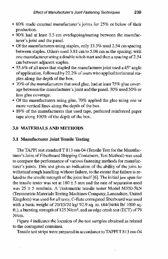
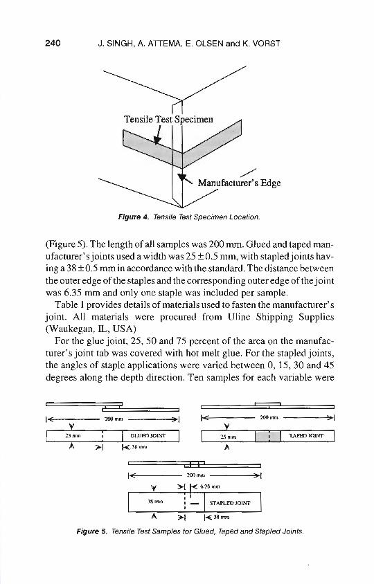
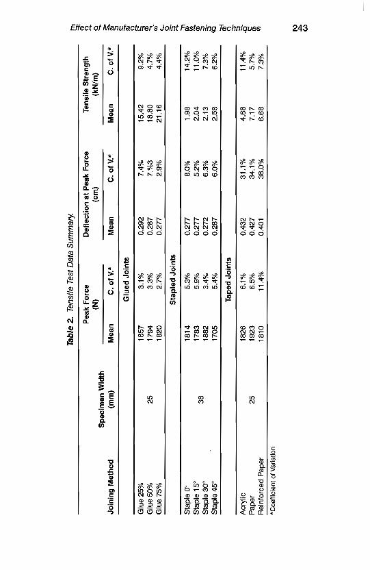
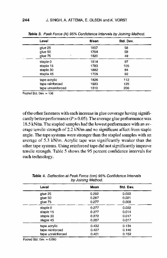
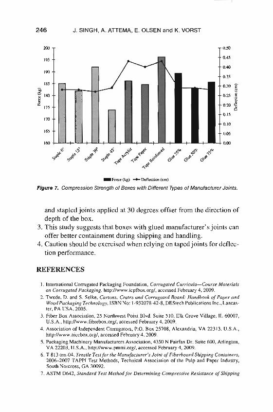