effect of koppers pole additive technology on the
TRANSCRIPT
WDC-2011-05am Koppers
1
Effect of Koppers Pole Additive Technology on the Resistance
To Gaff Penetration in Southern Pine Utility Poles
Report #: WDC-2011-05am Koppers
Dr. Jun Zhang
Koppers
Research Division
1141 Anne St., Griffin, GA 30224
Tel. (770) 233-4230
Submitted By:
Wood Durability Laboratory
Louisiana Forest Products Development Center
School of Renewable Natural Resources
LSU Agricultural Center
Baton Rouge, LA 70803
Tel. (225)578-4255
Fax (225)578-4251
September 22, 2020
This report shall not be reproduced except in full without approval of the laboratory.
We kindly request that all public references to the contest of this report be attributed to
“LSU AgCenter’s Wood Durability Laboratory”
TABLE OF CONTENTS

WDC-2011-05am Koppers
2
SIGNATORIES……………………………………………………..………....……....….3
INTRODUCTION….……………………………………………..…………..…....……..4
MATERIALS & METHODS………...………………………..…………….….……..….4
RESULTS AND DISCUSSION.... ……………………………………… ………..……8
SUMMARY OF RESULTS…..…………………..……………..………………….……15
WDL IAS Certificate of Accreditation ………..………...…..…………………...…..….16
END OF REPORT……………………………………………………………………….19

WDC-2011-05am Koppers
3
Report approved by:
Date: 9/22/20
Qinglin Wu, Ph.D.
Professor, Wood Science
Wood Durability Laboratory, Quality Manager
Phone: (225) 578-8369
Fax: (225) 578-4251
E-mail: [email protected]
Report prepared by:
Date: 9/22/20
J.P. Curole
Research Associate
Phone: (225) 578-4157
Fax: (225) 578-4251
E-mail: [email protected]

WDC-2011-05am Koppers
4
INTRODUCTION
The Wood Durability Laboratory (WDL) at Louisiana State University AgCenter was
contracted by Koppers, Griffin, GA to perform gaff hardness testing on southern pine pole
sections treated with CCA, Pentachlorophenol and CCA plus two pole additive systems,
Koppers Oil Emulsion and Wolman ETTM. The additive systems are designed to improve
the climbing characteristics of CCA treated utility poles.
Surface hardness was assessed by means of gaff penetration testing using two different
lineman gaffs. One gaff selected for testing was recommended for general pole climbing,
while the second gaff was specifically recommended by the supplier for climbing CCA
treated poles. In addition to gaff hardness testing, surface hardness was measured with a
Pilodyn 6J.
MATERIALS AND METHODS
A. Pole Sections
Thirty six, 3 foot long pole sections were received from Koppers for gaff and Pilodyn
hardness testing at the WDL. The pole sections and associated treatments are summarized
in Table 1 below. The letter designations associated with each pole number represent the
location within each parent pole, with the “A” sections being cut from the butt of the
respective poles and the “I” sections being cut from 24 to 27-feet along the length of the
pole (Figure 1).
Table 1. Pole section treatment identification.
Treatment Pole Section ID
CCA-C (control group)
8B, 8E, 8H
9B, 9E, 9H
10B, 10E, 10H
CCA/Koppers Oil Emulsion
8C, 8F, 8I
9C, 9F, 9I
10C, 10F, 10I
Pentachlorophenol
11B, 11E, 11H
12B, 12E, 12H
13B, 13E, 13H
CCA/Wolman ETTM
14B, 14E, 14H
15B, 15E, 15H
16B, 16E, 16H

WDC-2011-05am Koppers
5
Figure 1. Cutting of full-length utility poles into 3 foot long test sections.
B. Conditioning and Drying
Upon receipt from Koppers, the pole sections were placed outdoors under an open-sided
overhang for conditioning to constant moisture contents (MC). This overhang was
designed to protect the sections from the weather while allowing maximum air flow. The
sections were kept upright during this stage of drying and were evenly spaced to promote
uniform drying.
A Delmhorst RDM-3 resistance type moisture meter was used to periodically monitor the
moisture content of each pole section at a depth of 1 inch. The pole sections were also
weighed periodically to monitor moisture loss. Total drying time for the pole sections
ranged from 3 to 5 months.
C. Gaff Hardness Testing
Gaff hardness testing was performed using LSU’s Instron Universal Testing machine
(Model #5582) (See Figure 2). The test setup used was designed to reproduce the principal
movement of the gaff in penetrating a wood pole.

WDC-2011-05am Koppers
6
The equipment consisted of a jig mounted to the Instron base that held the pole sections at
a 20 degree angle from vertical direction. Lineman gaffs were attached using threaded pins
to a steel billet that was affixed to the load cell of the Instron Testing Machine. The gaffs
were mounted to the billet so that they were perfectly in line with one another.
Two different lineman gaffs were used to evaluate the effectiveness of the Koppers Oil
Emulsion treatment when compared to CCA only, Pentachlorophenol (Penta) and Wolman
ET (ET). The gaffs were identified as follows:
• Buckingham T9106A – Screw Style Replaceable CCA Pole Gaff.
• Buckingham T9206A – Screw Style Replaceable Pole Gaff.
The T9106A gaff is designed to penetrate hard CCA poles, while the T9206A gaff is
designed for general pole climbing. A total of 5 gaffs of each type were used and were
randomly assigned to each pole section to smooth out any variation caused by dulling.
In addition to the pole sections being mounted at a 20 degree angle from vertical direction,
both gaff styles used in this study were designed with a 16 degree angle between the upper
and lower shafts of the gaff. The combination of these two angles resulted in a penetration
angle of approximately 36 degrees to the central axis of the test specimens, which
corresponds to the average angle measured on a lineman climbing the pole.
The pole stubs were carefully positioned on the test bench so as to avoid knots and other
wood defects (e.g., split). Once the test stubs were mounted on the Instron machine, the
load head was lowered until the gaff was in contact with the pole surface. A force of 5
pounds was applied to the pole sections prior to testing to ensure that the gaff was fully
seated. The load head was then displaced 0.475 inches at a rate of 0.50 in./min. A load
sensor/cell was used to measure the applied force in the axis of the gaff. A total of 10
replicate readings were taken for each treatment/gaff combination.
D. Pilodyn Hardness Testing
In addition to gaff hardness testing, surface hardness of the pole sections was measured
with a 6 joule Pilodyn with a 2.5 mm diameter blunt end probe (Pilodyn 6 J, Proceq SA,
Zurich, Switzerland). Five measurements were taken at an angle of 90 degrees in the
vicinity of the gaff hardness tests (See Figure 3).
Figure 2. Gaff hardness testing.
Figure 2. Gaff hardness testing.
WDC-2011-05am Koppers
7
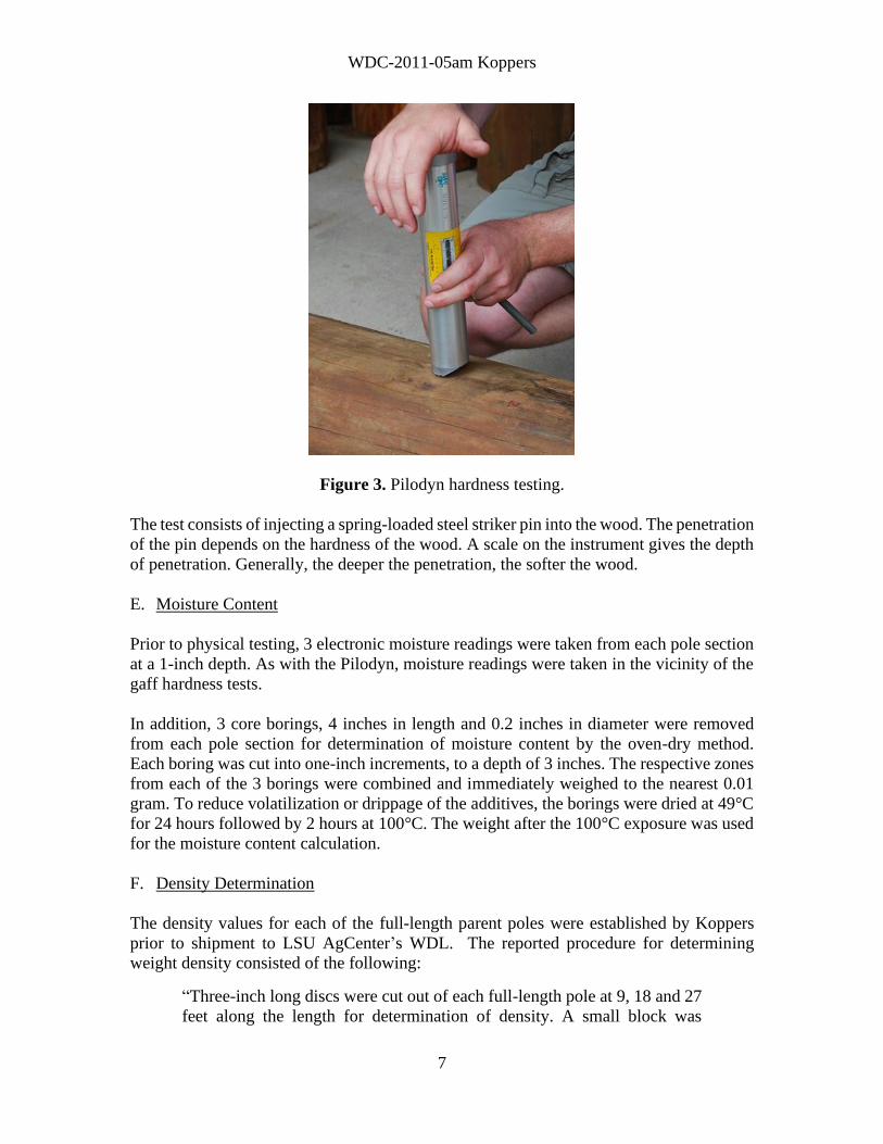
Figure 3. Pilodyn hardness testing.
The test consists of injecting a spring-loaded steel striker pin into the wood. The penetration
of the pin depends on the hardness of the wood. A scale on the instrument gives the depth
of penetration. Generally, the deeper the penetration, the softer the wood.
E. Moisture Content
Prior to physical testing, 3 electronic moisture readings were taken from each pole section
at a 1-inch depth. As with the Pilodyn, moisture readings were taken in the vicinity of the
gaff hardness tests.
In addition, 3 core borings, 4 inches in length and 0.2 inches in diameter were removed
from each pole section for determination of moisture content by the oven-dry method.
Each boring was cut into one-inch increments, to a depth of 3 inches. The respective zones
from each of the 3 borings were combined and immediately weighed to the nearest 0.01
gram. To reduce volatilization or drippage of the additives, the borings were dried at 49°C
for 24 hours followed by 2 hours at 100°C. The weight after the 100°C exposure was used
for the moisture content calculation.
F. Density Determination
The density values for each of the full-length parent poles were established by Koppers
prior to shipment to LSU AgCenter’s WDL. The reported procedure for determining
weight density consisted of the following:
“Three-inch long discs were cut out of each full-length pole at 9, 18 and 27
feet along the length for determination of density. A small block was

WDC-2011-05am Koppers
8
accurately machined from the outer 1-inch of each disc. The blocks were
accurately measured and weighed. The blocks were then dried at 49°C for
24 hours followed by 2 hours at 100°C. The weight after the 100°C exposure
was used for the moisture content calculation.”
G. Pole Section Assay
For the pole sections treated with the experimental additives, a drill bit 0.5-inch in diameter
was used to collect wood shavings from the outer ½-inch of each section. To ensure
sufficient material for analysis, a total of 40 locations were assayed per section. The
shavings were collected and returned to Koppers for determination of percentages and
ratios of the respective additives.
RESULTS AND DISCUSSION
The data collected for this evaluation is summarized in Tables 4 through 7 and visually
displayed in corresponding Figures 4 through 7. The following is a summation of the data
presented in each;
• Table 4, Figure 4 – Gaff Hardness for Buckingham CCA Pole Gaff.
• Table 5, Figure 5 – Gaff Hardness for Buckingham General-Purpose Gaff.
• Table 6, Figure 6 – Pilodyn Hardness.
• Table 7, Figure 7 – Moisture Content.
A. Pole Section Assay
The average assay results for the 9 pole sections from each respective treatment are
presented in Table 2 below.
Table 2. Summary of pole section retention results.
Retention, PCF
Treatment
Replicate
Pole
Sections
CCA by
Gauge
CCA by
Assay
Oil by
Gauge
Oil by
Assay1
CCA-C (control group) 9 0.68 0.59 N/A N/A
CCA/ Koppers Oil
Emulsion 9 0.61 0.57 0.69 1.02
Pentachlorophenol 9 N/A N/A 0.45 0.40
CCA/Wolman ETTM 9 0.60 N/A Not
Provided 1.20
1 The assay zone for the Koppes Oil Emulsion, Wolman ETTM and Penta treated pole
sections was 0.0 to 0.5” from the pole surface.
WDC-2011-05am Koppers
9
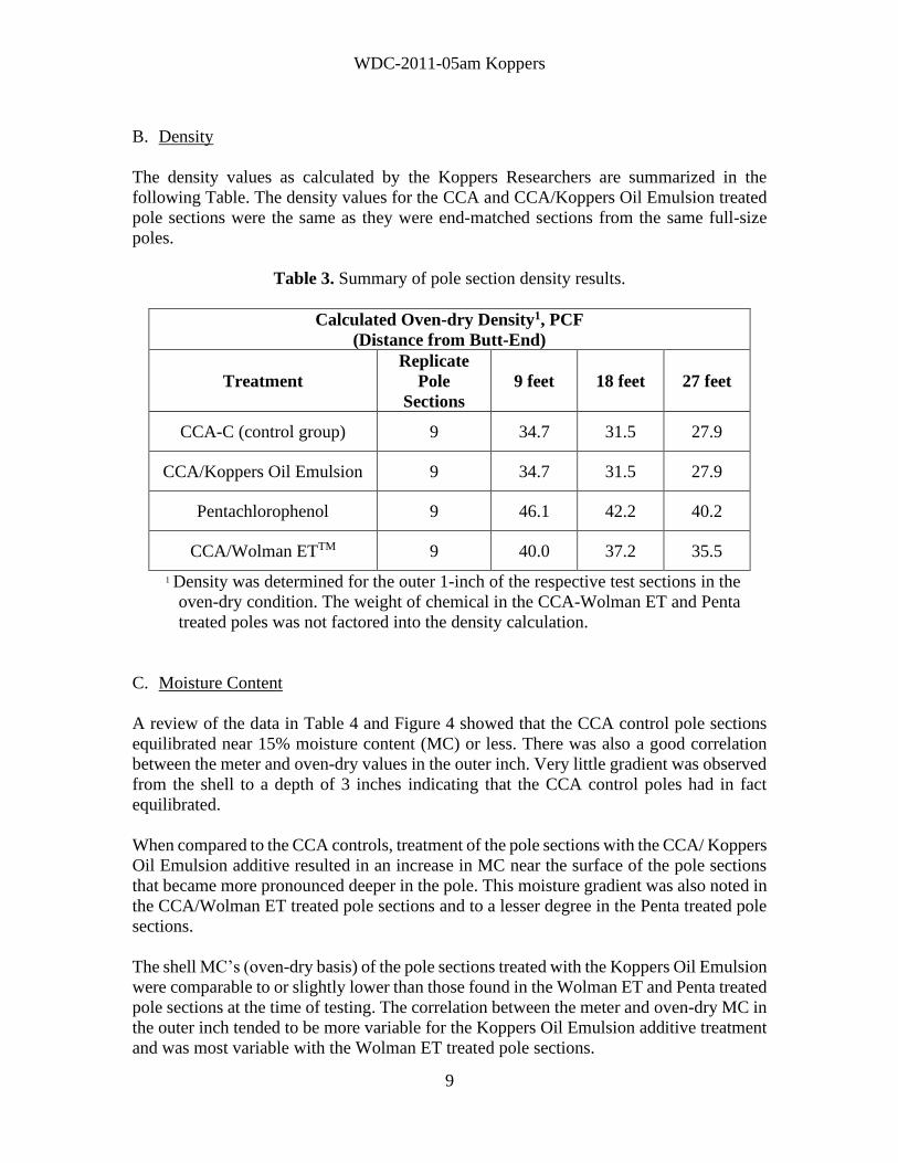
B. Density
The density values as calculated by the Koppers Researchers are summarized in the
following Table. The density values for the CCA and CCA/Koppers Oil Emulsion treated
pole sections were the same as they were end-matched sections from the same full-size
poles.
Table 3. Summary of pole section density results.
Calculated Oven-dry Density1, PCF
(Distance from Butt-End)
Treatment
Replicate
Pole
Sections
9 feet 18 feet 27 feet
CCA-C (control group) 9 34.7 31.5 27.9
CCA/Koppers Oil Emulsion 9 34.7 31.5 27.9
Pentachlorophenol 9 46.1 42.2 40.2
CCA/Wolman ETTM 9 40.0 37.2 35.5
1 Density was determined for the outer 1-inch of the respective test sections in the
oven-dry condition. The weight of chemical in the CCA-Wolman ET and Penta
treated poles was not factored into the density calculation.
C. Moisture Content
A review of the data in Table 4 and Figure 4 showed that the CCA control pole sections
equilibrated near 15% moisture content (MC) or less. There was also a good correlation
between the meter and oven-dry values in the outer inch. Very little gradient was observed
from the shell to a depth of 3 inches indicating that the CCA control poles had in fact
equilibrated.
When compared to the CCA controls, treatment of the pole sections with the CCA/ Koppers
Oil Emulsion additive resulted in an increase in MC near the surface of the pole sections
that became more pronounced deeper in the pole. This moisture gradient was also noted in
the CCA/Wolman ET treated pole sections and to a lesser degree in the Penta treated pole
sections.
The shell MC’s (oven-dry basis) of the pole sections treated with the Koppers Oil Emulsion
were comparable to or slightly lower than those found in the Wolman ET and Penta treated
pole sections at the time of testing. The correlation between the meter and oven-dry MC in
the outer inch tended to be more variable for the Koppers Oil Emulsion additive treatment
and was most variable with the Wolman ET treated pole sections.

WDC-2011-05am Koppers
10
The presence of the moisture gradients in the pole sections provides evidence that they
had not yet completely dried or equilibrated at the time of testing. This indicates that the
Koppers Oil Emulsion additive retards the drying rate considerably much like that seen
with the Wolman ET additive.
Table 4. Average Moisture Content of Pole Sections at Time of Testing.
Moisture Content1
Oven-Dry Method
Treatment
RDM-3
Meter (1
inch)
0-1 inch 1-2 inches 2-3 inches
`0.59 PCF CCA Control 13.3 12.2 15.1 14.8
1.02 PCF Koppers Oil
Emulsion 18.8 14.6 22.0 27.7
1.20 PCF Wolman ETTM 33.0 20.7 42.5 40.4
0.40 PCF Penta 19.2 20.6 28.8 25.3
1 Average of 9 pole sections, 10 readings per section.
Figure 4. Average Moisture Content of Pole Sections at Time of Testing.

WDC-2011-05am Koppers
11
A. Gaff Hardness Testing
As moisture content and density are known to have an effect on the surface hardness of
utility poles, both variables must be considered when evaluating the softening effect of the
test formulations. Density was not considered a contributing factor to changes in gaff
hardness for the test poles treated by Koppers as the experimental design evenly distributed
density across the entire population of test poles. Comparisons to commercial controls were
somewhat more difficult as the pole densities did vary somewhat.
Gaff hardness testing of southern pine pole sections treated with the Koppers Oil Emulsion
treating system at a loading of 1.02 pcf in the outer 0.5 inch, showed a pronounced
reduction in surface hardness over the CCA treated controls. The shell MCs of the CCA
control pole sections were generally lower than those for the additive systems. Thus, some
degree of surface hardness can be attributed to the low moisture content in the control poles.
This contribution is thought to be minor given the relatively large separation in gaff
hardness between the additive treatments and controls.
When comparing the effect on gaff hardness of the Koppers Oil Emulsion treating system
to the Wolman ET and Penta treatments, the oil retention level, surface MC and density
must be reviewed carefully as these poles were commercially treated, thus the test sections
did not come from the same parent poles.
The average oil retention level for the Wolman ET treated pole sections was 1.20 pcf while
the oil loading for the Koppers Oil Emulsion was 1.02 pcf. The shell MC for the Koppers
Oil Emulsion treated pole sections tended to be slightly lower on average than the Wolman
ET and Penta treated sections. The average density for the pole sections treated with CCA
and the Koppers Oil Emulsion was 31 pcf. The average density of the Wolman ET and
Penta pole sections was 38 and 43 pcf, respectively.
A review of the gaff hardness data summarized in Tables 5-6 and associated Figures 5-6,
showed that the Koppers Oil Emulsion treated poles sections were comparable to Wolman
ET treated pole sections and slightly better than Penta. The higher density values of the
Wolman ET and Penta pole sections may have had a negative impact on surface hardness,
but the degree of impact is unknown. In contrast, the higher oil loading of the Wolman ET
test poles likely had a positive influence on gaff hardness. Again the degree of impact is
unknown.
WDC-2011-05am Koppers
12
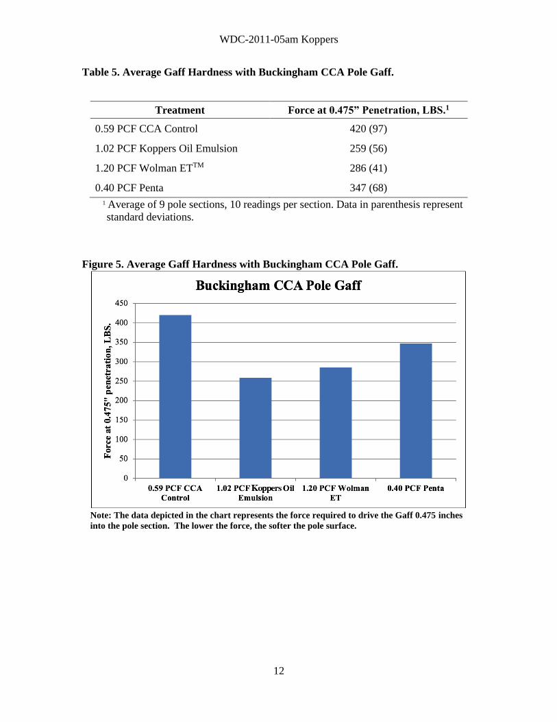
Table 5. Average Gaff Hardness with Buckingham CCA Pole Gaff.
Treatment Force at 0.475” Penetration, LBS.1
0.59 PCF CCA Control 420 (97)
1.02 PCF Koppers Oil Emulsion 259 (56)
1.20 PCF Wolman ETTM 286 (41)
0.40 PCF Penta 347 (68)
1 Average of 9 pole sections, 10 readings per section. Data in parenthesis represent
standard deviations.
Figure 5. Average Gaff Hardness with Buckingham CCA Pole Gaff.
Note: The data depicted in the chart represents the force required to drive the Gaff 0.475 inches
into the pole section. The lower the force, the softer the pole surface.

WDC-2011-05am Koppers
13
Table 6. Average Gaff Hardness with Buckingham General-Purpose Pole Gaff.
Treatment Force at 0.475” Penetration, LBS.1
0.59 PCF CCA Control 426 (117)
1.02 PCF Koppers Oil Emulsion 250 (42)
1.20 PCF Wolman ETTM 239 (44)
0.40 PCF Penta 300 (63)
1 Average of 9 pole sections, 10 readings per section. Data in parenthesis represent
standard deviations.
Figure 6. Average Gaff Hardness with Buckingham General-Purpose Pole Gaff.
Note: The data depicted in the chart represents the force required to drive the Gaff 0.475 inches
into the pole section. The lower the force, the softer the pole surface.
B. Pilodyn Hardness Testing
When interpreting Pilodyn penetration data, it is important to note that deeper the
penetration of the striker pin, the softer the wood. As with gaff hardness testing, the
inclusion of the Koppers Oil Emulsion in the CCA treated pole sections showed an
improvement in Pilodyn hardness over the CCA control pole sections, with a marked

WDC-2011-05am Koppers
14
increase in pin penetration (Table 7, Fig. 7). Again, some degree of surface hardness may
be attributed to the low moisture content in the control poles.
The average Pilodyn penetration was found to be the greatest for the pole sections treated
with the Koppers Oil Emulsion, indicating that this treatment afforded the greatest
reduction in surface hardness. The Pilodyn penetrations for the Wolman ET and Penta
treated sections were similar and slightly less than that for the Koppers Oil Emulsion
treated sections. Similar to gaff hardness testing, the higher density values of the Wolman
ET and Penta pole sections may have had a negative impact on Pilodyn hardness, but the
degree of impact is unknown. However, the fact that the pole sections treated with the
Koppers Oil Emulsion had lower moisture levels and lower oil loadings than the Wolman
ET treated sections, provides evidence that the Koppers additive system performs similarly.
Table 7. Average Pilodyn Hardness.
Treatment Pilodyn1
0.59 PCF CCA Control 11.8 (1.6)
1.02 PCF Koppers Oil Emulsion 14.6 (2.2)
1.20 PCF Wolman ETTM 12.4 (1.1)
0.40 PCF Penta 12.0 (1.0) 1 Average of 9 pole sections, 10 readings per section. Data in parenthesis represent standard
deviations.
Figure 7. Average Pilodyn Hardness.
Note: The data depicted in the chart represents the penetration of the striker pin into the pole
section. The higher the Pilodyn Hardness (deeper the penetration), the softer the pole surface.

WDC-2011-05am Koppers
15
SUMMARY OF RESULTS
A review of the gaff hardness and Pilodyn penetration data obtained from this testing
showed that the Koppers Oil Emulsion, at a loading of 1.02 pcf, provided a pole surface
hardness that was comparable to Wolman ET at a loading of 1.20 pcf. The surface hardness
of the pine poles treated with the Koppers Oil Emulsion was also slightly improved over
that of the Penta treated southern pine pole sections.

WDC-2011-05am Koppers
16

WDC-2011-05am Koppers
17

WDC-2011-05am Koppers
18

WDC-2011-05am Koppers
19
END OF REPORT