efficient pixel-accurate rendering of animated curved surfaces · efficient pixel-accurate...
TRANSCRIPT

Efficient Pixel-accurate Rendering of Animated CurvedSurfaces
Young In Yeo, Sagar Bhandare, Jorg Peters
University of Florida, USA,[email protected]
Abstract. To efficiently animate and render large models consisting of bi-cubicpatches in real time, we split the rendering into pose-dependent, view-dependent(Compute-Shader supported) and pure rendering passes. This splitavoids recom-putation of curved patches from control structures and minimizes overhead dueto data transfer – and it integrates nicely with a technique to determine a near-minimal tessellation of the patches while guaranteeing sub-pixel accuracy. OurDX11 implementation generates and accurately renders 141,000 animated bi-cubic patches of a scene in the movie ‘Elephant’s Dream’ at more than 300 framesper second on a 1440×900 screen using one GTX 580 card.
1 Introduction
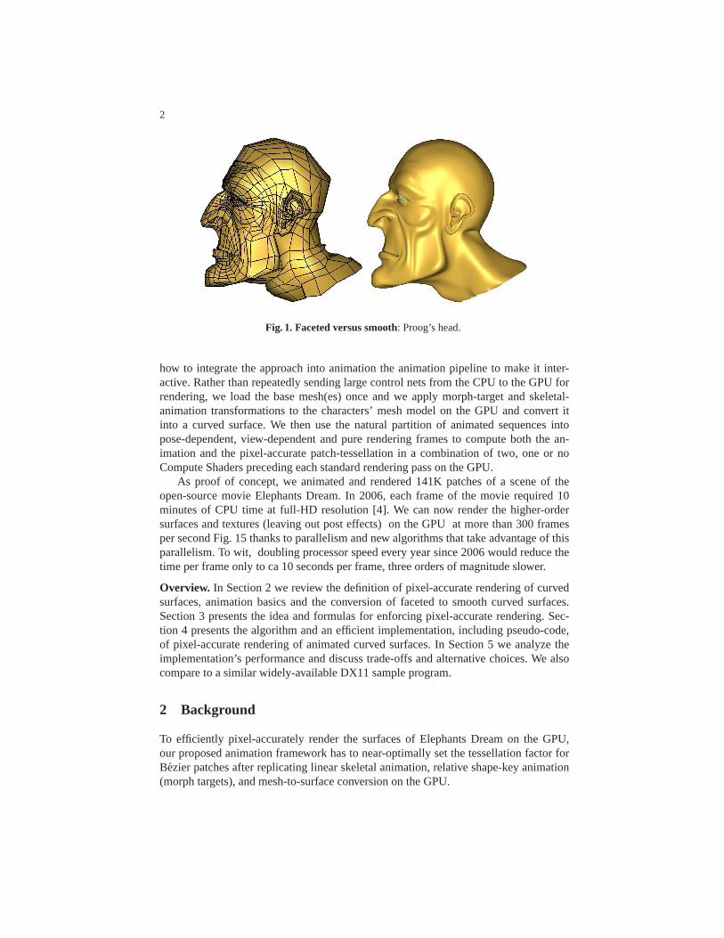
Curved, smooth, piecewise polynomial surfaces have becomestandard in high end,movie-quality animation. Subdivision surfaces [1,2], spline (NURBS) surfaces or Bezierpatch-based surfaces are chosen over polygonal, polyhedral, or faceted-based represen-tations both for aesthetic reasons and for their ability to represent models more com-pactly. In particular, curved surfaces yield more life-like transitions and silhouettes and,in principle, support arbitrary levels of resolution without exhibiting polyhedral arti-facts (see Fig. 1). But while curved surfaces are commonly used in cinematic productionand geometric design, they are not commonly used for interactive viewing. Animationartists and designers typically work off faceted models at agiven resolution and have tocall special off-line rendering routines to inspect the true outcome of their work. At theother end of the spectrum, game designers opt for coarsely-faceted models, made moreacceptable by careful texturing, to achieve real-time rendering with limited resourcesunder competing computational demands, e.g. computing game physics. In an attemptto narrow the gap, a number of mesh-to-surface conversion algorithms have been devel-oped in the past years that run efficiently on the GPU (see Section 2). But so far theirrendering has depended on screen projection heuristics without guarantees of accuracy.
The present paper explains how to render, at interactive rates, and on high-resolutionscreens, a substantial number of animated curved surfaces free of perceptible polyhedralartifacts, parametric distortion and pixel dropout. The paper leverages and extends theauthors’ approach [3] for efficiently determining the near-minimal tessellation densityrequired forpixel-accurate rendering (see Section 2). Determining the near-minimaltessellation density requires, depending on the model, between 1% and 5% extra work.However, by avoiding overtessellation, pixel-accurate rendering is often faster than ren-dering based on heuristics (see Fig. 2, middle and right). Specifically, the paper shows
2
Fig. 1. Faceted versus smooth: Proog’s head.
how to integrate the approach into animation the animation pipeline to make it inter-active. Rather than repeatedly sending large control nets from the CPU to the GPU forrendering, we load the base mesh(es) once and we apply morph-target and skeletal-animation transformations to the characters’ mesh model onthe GPU and convert itinto a curved surface. We then use the natural partition of animated sequences intopose-dependent, view-dependent and pure rendering framesto compute both the an-imation and the pixel-accurate patch-tessellation in a combination of two, one or noCompute Shaders preceding each standard rendering pass on the GPU.
As proof of concept, we animated and rendered 141K patches ofa scene of theopen-source movie Elephants Dream. In 2006, each frame of the movie required 10minutes of CPU time at full-HD resolution [4]. We can now render the higher-ordersurfaces and textures (leaving out post effects) on the GPU at more than 300 framesper second Fig. 15 thanks to parallelism and new algorithms that take advantage of thisparallelism. To wit, doubling processor speed every year since 2006 would reduce thetime per frame only to ca 10 seconds per frame, three orders ofmagnitude slower.
Overview. In Section 2 we review the definition of pixel-accurate rendering of curvedsurfaces, animation basics and the conversion of faceted tosmooth curved surfaces.Section 3 presents the idea and formulas for enforcing pixel-accurate rendering. Sec-tion 4 presents the algorithm and an efficient implementation, including pseudo-code,of pixel-accurate rendering of animated curved surfaces. In Section 5 we analyze theimplementation’s performance and discuss trade-offs and alternative choices. We alsocompare to a similar widely-available DX11 sample program.
2 Background
To efficiently pixel-accurately render the surfaces of Elephants Dream on the GPU,our proposed animation framework has to near-optimally setthe tessellation factor forBezier patches after replicating linear skeletal animation, relative shape-key animation(morph targets), and mesh-to-surface conversion on the GPU.
3
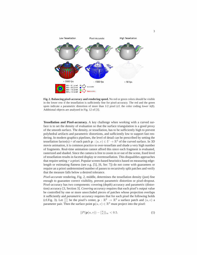
Fig. 2. Balancing pixel-accuracy and rendering speed.No red or green colors should be visiblein the lower row if the tessellation is sufficiently fine for pixel-accuracy. Thered and the greenspots indicate a parametric distortion of more than 1/2 pixel (cf. the color coding lower left).Additional objects are analyzed in Fig. 12 of [3].
Tessellation and Pixel-accuracy.A key challenge when working with a curved sur-face is to set the density of evaluation so that the surface triangulation is a good proxyof the smooth surface. The density, or tessellation, has to be sufficiently high to preventpolyhedral artifacts and parametric distortions, and sufficiently low to support fast ren-dering. In modern graphics pipelines, the level of detail can be prescribed by setting thetessellation factor(s)τ of each patchp : (u, v) ∈ U → R3 of the curved surface. In 3Dmovie animation, it is common practice to over-tessellate and shade a very high numberof fragments. Real-time animation cannot afford this sinceeach fragment is evaluated,rasterized and shaded. Since the camera is free to zoom in or out of the scene, fixed levelof tessellation results in faceted display or overtessellation. This disqualifies approachesthat require settingτ a priori. Popular screen-based heuristics based on measuring edge-length or estimating flatness (see e.g. [5], [6, Sec 7]) do notcome with guarantees orrequire an a priori undetermined number of passes to recursively split patches and verifythat the measure falls below a desired tolerance.
Pixel-accurate rendering, Fig. 2, middle, determines the tessellation density (just) fineenough to guarantee correct visibility, prevent parametric distortion or pixel-dropout.Pixel-accuracy has two components: covering (depth) accuracy and parametric (distor-tion) accuracy [3, Section 3].Covering accuracy requires that each pixel’s output valuebe controlled by one or more unoccluded pieces of patches whose projection overlapsit sufficiently andparametric accuracy requires that for each pixel the following holds(cf.Fig. 3). Let [ xy ] be the pixel’s center,p : R2 → R3 a surface patch and(u, v) aparameter pair. Then the surface pointp(u, v) ∈ R3 must project into the pixel:
‖P (p(u, v))− [ xy ]‖∞ < 0.5. (1)

4
Inequality (1) preventsparametric distortion: if P (p(u, v)) lies outside the pixel asso-
Fig. 3. Triangulation and projection distorting the image of a curved surface. Pixel-accuraterendering guarantees that the distortion is at below pixel level.
ciated with parameters(u, v) then the wrong texture, normal or displacement is com-puted causing artifacts incompatible with accurate rendering. Parametric inaccuracy iscolor-encoded in Fig. 2: lack of accuracy is shown in red and green. Predictably, toocoarse a tessellation yields a high frame rate and too fine a tessellation slows down ren-dering. The largely grey coloring of the teapot in Fig. 3, rowtwo, under pixel-accuraterendering, indicating a distortion just below the pixel threshold, is therefore highly de-sirable. Work similar to [3], but based on the bounds in [7] includes [8] and most re-cently [9].
Skeletal animation.The most common technique for character animation, used by theartists of Elephants Dream, is linear blend skinning, also known as linear vertex blend-ing or skeletal subspace deformation [10]. Here a characteris defined by a template,a faceted model, called skin. The models animation or deformation is defined by atime-varying set of rigid transformations, called bones, that are organized into a treestructure, called skeleton. Any vertex position in a linearblend skin is expressed as alinear combination of the vertex transformed by each bone’scoordinate system: at timeti, a convex combinationωk of bone transformationsRk is applied to each skin vertexinitial positionv(0):
v(t) =(
∑
k
ωkRk(t))
v(0),∑
k
ωk = 1. (2)
The weightsωk are assigned by the artist. Section 4 provides pseudo-code.Since this direct linear combination of rotation matrices generically does not yield
a valid rotation, a number of improvements have been suggested [11,12]. In particulardual quaternions [12] are sufficiently simple to have been implemented in Blender. Our

5
framework is agnostic to the choice of animation since its implementation as a ComputeShader allows alternative animation techniques to be substituted such as deformationof the mesh points with respect to control cages (see e.g. [13,14,15,16]). However,since the artists of Elephants Dream used linear blend skinning, and compensated forits shortcomings, our real-time rendering applies linear,skeletal animation.
(a) without shape keys (b) with shape keys
Fig. 4. Emo’s mouth opened withshape keys.
Shape Keys.For more nuanced, say facial expressions, Elephants Dream,and henceour implementation, additionally applies shape keys, alsoknown as morph targets orblend shapes. Shape keys average between morph targets representing standard poses(see e.g. [17] for a detailed explanation.)
Mesh-to-Surface Conversion.In recent years, a number of algorithms have been de-veloped to use polyhedral meshes as control nets of curved surfaces and efficientlyevaluate these curved surfaces on the GPU. Such algorithms include conversions topiecewise polynomial and rational representation [18,19,20,21] as well as subdivision[22,23,6,24]. Our framework is agnostic to the choice of conversion algorithm. To beable to compare our GPU implementation to a widely accessible implementation, wechose Approximate Catmull-Clark (ACC) [20]: optimized shader code of ACC ani-mation, SubD11, is distributed with MicroSoft DX11 [25]. The output of ACC is onebi-cubic patch patch for each face of the (refined) control mesh (plus a pair of tangentpatches to improve the impression of smoothness as in [26]).Note that parametric accu-racy is not concerned with whether ACC provides a good approximation to subdivisionsurfaces, an issue of independent interest (cf. [27,28]).
3 Computing near-minimal accurate tessellation levels
The two main ingredients that make pixel-accurate rendering efficient are avoiding re-cursion and triangulating as coarsely as possible while guaranteeing pixel-accuracy (seeFig. 5). This section explains how to address both challenges by computing a near-minimal tessellation factorτ in a single step according to the approach in [3]. The tes-sellation factor is computed with the help of slefe-boxes [29]. Bilinear interpolants ofthese slefe-boxes, called slefe-tiles, sandwich the curved surface and the triangulation

6
Fig. 5. Optimal tessellation of curved surfaces.Fewer, hence bigger triangles improve effi-ciency. (Note the different use of color-coding from Fig. 2).
as illustrated in Fig. 6. Such slefe-boxes are not traditional bounding boxes enclosing apatch. Rather the maximal width of slefe-boxes gives an upper bound on the varianceof the exact curved surface from triangulation. This reflects the goal: to partition thedomain sufficiently finely so that the variance and hence the ‘width’ of the all projectedslefe-boxes and therefore of the slefe-tiles falls below a prescribed tolerance, e.g. halfthe size of a pixel.
Fig. 6. The bi-linear interpolants to groups of four slefe-boxes defineslefe-tilesthat locally en-close the surface. Note that the tiles, while useful of collision, arenever explicitly computedforthe pixel-accurate rendering.
Since knot insertion stably converts NURBS patches of degree (d1, d2) to tensor-product patches in Bezier-form (glMap2 in OpenGL) with coefficientscij ∈ R3 and

7
basis functionsbdj ,
p(u, v) :=
d1∑
i=0
d2∑
j=0
cijbd2
j (v)bd1
i (u), (u, v) ∈ [0..1]2, (3)
and since subdivision surfaces can be treated as nested rings of such patches, we fo-cus on tensor-product Bezier patches. (Knot insertion can be a pre-processing stepordone on the fly on the GPU. Rational patches are rarely used in animation; if needed,for strictly positive weights, bounds in homogeneous spaceplus standard estimates ofinterval arithmetic do the trick.) Moreover, slefe-boxes for patches in tensor-productform can be derived from bounds in one variable and the computations for buildingslefe-boxes are separate in eachx, y andz coordinate. We can therefore simplify thediscussion in the next subsection to one univariate polynomial piecep in Bezier-formwith coefficientscj ∈ R and parameteru ∈ [0 . . 1]:
p : R → R, u 7→ p(u) :=
d∑
j=0
cjbdj (u), bdj :=
(
d
j
)
(1− u)d−juj .
Subdividable Linear Efficient Function Enclosures, abbreviated asslefes, tightlysandwich non-linear functionsp, such as polynomials, splines and subdivision surfaces,between simpler, piecewise linear, lower and upper functions,p andp:
p ≤ p ≤ p,
[30,31,32,33,29,34,35]. Specifically, in one variable, [30] shows that (cf. Fig. 7,left)
p(t) ≤ p(t) := ℓ(t) +d−1∑
j=1
max{0,∇2jp} a
dj
m(t) (4)
+
d−1∑
j=1
min{0,∇2jp} adj
m(t).
with the matching lower boundp obtained by exchangingmin andmax operators. Here
adj , j = 1, . . . , d− 1,
are polynomials that span the space of polynomials of degreed minus the linear func-
tions ℓ(t); adjm
is anm-piece upper andadjm
an m-piece lower bound onadj ; and
∇2jp := cj−1 − 2cj + cj+1 is a second difference of the control points. Ifp is a lin-
ear function, upper and lower bounds agree. The tightness ofthe bounds is importantsince loose bounds result in over-tessellation. Fig. 7b shows an example from [3], wherethe min-max or AABB bound is looser by an order of magnitude than the slefe-widthw := maxt∈[0..1] p(t)− p(t).
Being piecewise linear, the bounding functionsadj
mandadj
min (4) are defined by
their values at the uniformly-spaced break points. These values can be pre-computed.

8
bcontrol
bxx2
x1
x3x0
Lb
bcontrol
bxx2
x1
x3x0
Lb
width = 0.2767
control polygon
c0
c1
c2
c3
p
ℓ
p
w
min-max
a13a13
a13
a13
(a) (b)
Fig. 7. Theslefe-constructionfrom [29]. (a) The functionp(t) := −b31(t) + b32(t) and its upperboundp. (b) The lower bounda13 and the upper bounda13 tightly sandwiching the functiona1 := − 2
3b31(t) −
13b32(t), usingm = 3 segments. Table 1 showsw = max[0..1] p − p to be
< 0.07. The corresponding number for [7] (not illustrated) is68= 0.75 and for the min-max-
bound23.
t = 0 1/3 2/3 1
a31
30 -.370370.. -.296296.. 0
a313
-.069521.. -.439891.. -.315351.. -.008732..Table 1. Values atbreakpoints of a m = 3-piece slefe. This table and the tables for higherdegree can be downloaded [36]. Similar slefe-tables exist for splines with uniform knots [30].
Since, ford = 3, i.e. cubic functions,a32(1−t) = a31(t), Table 1 lists all numbers needed
to compute Fig. 7, e.g., fort = 1/3, the upper and lower breakpoint values−.370370..and−.439891... Moreover, by tensoring, the 8 numbers suffice to compute allboundsrequired for ACC patches: the tensor-product patch (3) can be bounded by computingthe upper valuescij , i = 0, . . . , d1 (for eachj = 0, . . . ,m2) of the 1-variable slefe inthe v direction and then treat the values as control points when computing the upperslefe in theu direction:
p(u, v) ≤d1∑
i=0
m2∑
j=0
cijb1j (v)b
d1
i (u) ≤m2∑
j=0
m1∑
i=0
cijb1i (u)b
1j (v).
Ensuring pixel-accuracyThe slefes just discussed are for functions, i.e. one coordinateof the image. Since we want to control the variance of the surface patches from theirtriangulation we now consider a patchp : R2 → R3 with three coordinates boundedby bilinear interpolants to upper and lower values at the grid points(ui, vj), i, j ∈{0, 1, . . . ,m}. For each(ui, vj), abbreviatingpij := p(ui, vj), pij := p(ui, vj), a

9
slefe-box is defined as
p(ui, vj) :=pij + pij
2+ [−1
2..1
2]3(pij − pij), (5)
where[− 12 ..
12 ]
3 is the0-centered unit cube. That is, the slefe-box is an axis-aligned boxin R3 (see red boxes in Fig. 8) centered at the average of upper and lower values.
p(ui, vj)
P (p(ui−1, vj))
p(ui−1, vj) P (p(ui, vj))
x, y pixel size
wxyxij , yij
xij , yij
Fig. 8. Projected slefe-boxes.The projected slefe-boxes (red) are enclosed by axis-alignedrectangles (blue, dashed) whose linear interpolant (grey area) encloses the image (here ofp([ui−1..ui], vj)). The (square-root of the) maximal edge-length of the dashed rectangles, inpixel size, determines the tessellation factorτp.
To measure parametric accuracy, we define the minimal screen-coordinate-alignedrectangle that encloses the screen projection[ xy ] := P (p(ui, vj)) of to the slefe-boxwith indexi, j (see the blue dashed rectangles in Fig. 8):
qij := [xij ..xij ]× [yij..yij ] ) P (p(ui, vj)). (6)
The maximal edge length over allqij is the parametricwidth wxy. This width is a closeupper bound on the variance from linearity in the parameterization since the width ofthe projected boxes dominates the width of the slefe-tiles –that therefore need not becomputed. The width shrinks to zero when the parameterization becomes linear.
We want to determine the tessellation factorτxy ∈ R so thatwxy < 1. Let wm(p)be the width of the projection of patchp measured for a slefe withm pieces andkma constant between1.5 and1, depending only onm. Since partitioning theu-domaininto 1/h segments, and re-representing the function over the smaller interval before re-applying the bound, scales the maximal second difference down quadratically toh2 itsoriginal size (cf. Fig. 9), partitioning both theu- and thev-domain into
τxy(m,p) := km√
wm(p) (7)

10
Fig. 9. Shrinkage of the widthfor a curve segment under subdivision.black: cubic curve, controlpolygon,blue: piecewise linear interpolant,red: slefe,
many pieces, confines the parameter distortion to below one unit (cf. Fig. 10) Analo-gously, the widthwz(m,p) of the depth componentz of the projection measures depthof the slefe-tiles and therefore trustworthiness of the z-buffer test for covering accuracy.
Fig. 10. Shrinkage of slefeunder h-fold subdivision.
To guarantee that any error due to linearization is below pixel size and the depththreshold tolz, we compute the width for lowm, saym = 2 or 3, and then apply (7) toobtain a safe tessellation factor of
τp := max{τxy(m,p), km√
wz(m,p)/tolz}. (8)
Fig. 5 shows that the resulting triangles are, as hoped for, typically much larger thanpixels and experiments confirm that (8) determines a near-minimalτp in the sense that,for typical models, already a 10% decrease inτp leads to pixel inaccuracy.
11
skeletal animation, conversion
CS (or PS)
updateτ
TE DS PS
grid generation evaluation shading
VS
look upτ
HS
GPU buffer:b, animation data,pt, �, τ , camera, materials, textures
newt
news
else
CS (or PS)
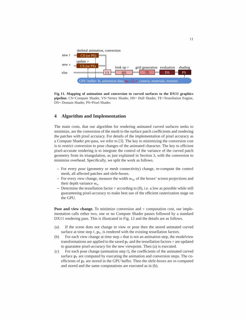
Fig. 11. Mapping of animation and conversion to curved surfaces tothe DX11 graphicspipeline. CS=Compute Shader, VS=Vertex Shader, HS= Hull Shader, TE=Tessellation Engine,DS= Domain Shader, PS=Pixel Shader.
4 Algorithm and Implementation
The main costs, that our algorithm for rendering animated curved surfaces seeks tominimize, are the conversion of the mesh to the surface patchcoefficients and renderingthe patches with pixel accuracy. For details of the implementation of pixel accuracy asa Compute Shader pre-pass, we refer to [3]. The key to minimizing the conversion costis to restrict conversion to pose changes of the animated character. The key to efficientpixel-accurate rendering is to integrate the control of thevariance of the curved patchgeometry from its triangulation, as just explained in Section 3, with the conversion tominimize overhead. Specifically, we split the work as follows.
– For everypose (geometry or mesh connectivity) change, re-compute the controlmesh, all affected patches and slefe-boxes.
– For everyview change, measure the widthwxy of the boxes’ screen projections andtheir depth variancewz.
– Determine the tessellation factorτ according to (8), i.e. a low as possible while stillguaranteeing pixel-accuracy to make best use of the efficient rasterization stage onthe GPU.
Pose and view change.To minimize conversion andτ computation cost, our imple-mentation calls either two, one or no Compute Shader passes followed by a standardDX11 rendering pass. This is illustrated in Fig. 12 and the details are as follows.
(a) If the scene does not change in view or pose then the storedanimated curvedsurface at time stept, pt, is rendered with the existing tessellation factors.
(b) For each view change at time steps that is not an animation step, the modelviewtransformations are applied to the savedpt and the tessellation factorsτ are updatedto guarantee pixel-accuracy for the new viewpoint. Then (a)is executed.
(c) For each pose change (animation stept), the coefficients of the animated curvedsurfacept are computed by executing the animation and conversion steps. The co-efficients ofpt are stored in the GPU buffer. Then the slefe-boxes are re-computedand stored and the same computations are executed as in (b).
12
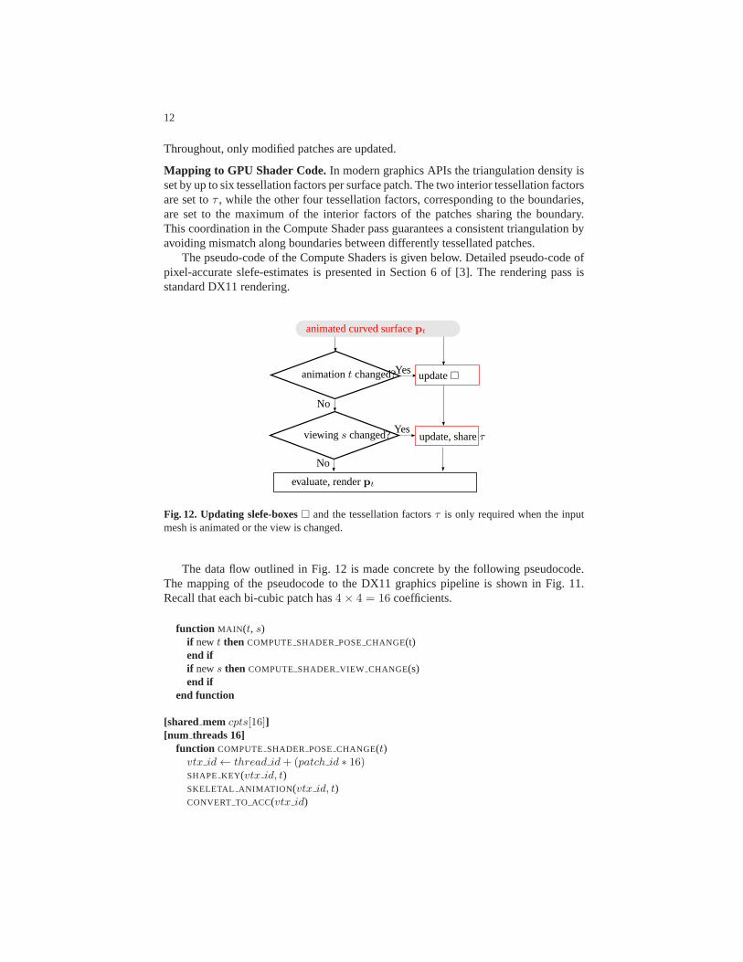
Throughout, only modified patches are updated.
Mapping to GPU Shader Code.In modern graphics APIs the triangulation density isset by up to six tessellation factors per surface patch. The two interior tessellation factorsare set toτ , while the other four tessellation factors, correspondingto the boundaries,are set to the maximum of the interior factors of the patches sharing the boundary.This coordination in the Compute Shader pass guarantees a consistent triangulation byavoiding mismatch along boundaries between differently tessellated patches.
The pseudo-code of the Compute Shaders is given below. Detailed pseudo-code ofpixel-accurate slefe-estimates is presented in Section 6 of [3]. The rendering pass isstandard DX11 rendering.
animationt changed?
viewings changed? update, shareτ
No
No
Yes
Yes
evaluate, renderpt
update�
animated curved surfacept
Fig. 12. Updating slefe-boxes� and the tessellation factorsτ is only required when the inputmesh is animated or the view is changed.
The data flow outlined in Fig. 12 is made concrete by the following pseudocode.The mapping of the pseudocode to the DX11 graphics pipeline is shown in Fig. 11.Recall that each bi-cubic patch has4× 4 = 16 coefficients.
function MAIN (t, s)if newt then COMPUTE SHADER POSE CHANGE(t)end ifif news then COMPUTE SHADER VIEW CHANGE(s)end if
end function
[shared mem cpts[16]][num threads 16]
function COMPUTE SHADER POSE CHANGE(t)vtx id← thread id+ (patch id ∗ 16)SHAPE KEY(vtx id, t)SKELETAL ANIMATION (vtx id, t)CONVERT TO ACC(vtx id)

13
end function
[shared memwidth[16]][num threads 16]
function COMPUTE SHADER VIEW CHANGE(s)vtx id← thread id+ (patch id ∗ 16)width[thread id]← project slefe(vtx id)synchronize threads()if thread id = 1 thenTF ← pick max width(width)save to gpu(TF buffer, patch id, TF )
end ifend function
function SHAPE KEY(vtx id, t)base sk ← get base shape key(vtx id)shaped vtx← (0, 0, 0)for sk in shape keys[vtx id] dosk wt← get shape key wt(vtx id, sk, t)shaped vtx += sk wt ∗ (sk.v[vtx id]− base sk.v[vtx id])
end forrest vtx[vtx id]← shaped vtx+ base sk.v[vtx id]
end function
function SKELETAL ANIMATION (vtx id, t)tot wt← sum influence weights(vtx id)final mat← zero matrix(4, 4)for bonei in influencing bones[vtx id] doposed bone mat← pose mat(bonei, t)rest bone mat inv ← rest mat inv(bonei)bone wt← get bone wt(vtx id, bonei)/tot wt
final mat += (rest bone mat inv ∗ posed bone mat ∗ bone wt)end forposed vtx[vtx id]← rest vtx[vtx id] ∗ final mat
end function
function CONVERT TO ACC(vtx id)cpts[thread id]← (0, 0, 0)for i← 0 to stencil size[vtx id] dostencil vtx← posed vtx[stencil lookup[vtx id, i]]cpts[thread id]+=stencil wt[vtx id, i] ∗ stencil vtx
end fornormalize(cpts[thread id])save to gpu(cpt buffer, vtx id, cpts[thread id])synchronize threads()slefe← update slefe(thread id)save to gpu(slefe buffer, vtx id, slefe)
end function

14
skeletal animation
GPU buffer:b, animation data,τglobal, camera, materials, textures
grid generationconversion
TE DS PSVS HS
evaluation shadingSubD11 [25]
Fig. 13. DX11 SubD11 implementation [25].CS=Compute Shader, VS=Vertex Shader, HS=Hull Shader, TE=Tessellation Engine, DS= Domain Shader, PS=Pixel Shader.
GPU processing % of totalskeletal animation + conversion 58slefe bounds 4
pose change total 62view change 6rendering pass 32
Table 2.Distribution of work per frame among pose, view and rendering. Pose change dominates.
5 Discussion and Comparison
Performance. Table 2 shows the work distribution of a rendering cycle. Theposechange consists of mesh animation and conversion plus recomputation of slefe-box ver-tices. The pose change dominates the work, but the recomputation of the slefe boundsaccounts for less than 4%. The slefe bounds and their projection make up ca 10% ofthe overall work. According to measurements in Section 7 of [3], the bounds are within12% of the optimal for widely-used, representative test examples in computer graphics(the tessellation factor in the implementation of [3] was inadvertently scaled by
√2).
Given that tight bounds reduce work when accurate renderingis required, it is not sur-prising that 10% computational overhead buys a considerable speedup compared to theovertessellation of conservatively-applied heuristics.
We used an NVidia GeForce GTX 580 graphics card with Intel Core 2 Quad CPUQ9450 at 2.66GHz with 4GB memory to render the geometry of themovie ElephantsDream. Elephants Dream is a 10-minute-long animated movie whose source is open.In 2006 it was reported to have taken 125 days to render, consuming up to 2.8GB ofmemory for each frame in Full-HD resolution (1920×1080) [4]. That is, each frametook on the order of 10 minutes to render. Since the ElephantsDream character meshesof Proog and Elmo contain triangles, but ACC requires a quadrilateral input mesh, weapplied the standard cure of one step of Catmull-Clark subdivision yielding 140,964curved surface patches for Proog and Emo together. In our implementation, we repli-cated Elephants Dream except that we did not apply post effects so as to isolate theeffect of improved patch rendering. The 141K textured bi-cubic ACC patches renderat over 300 frames per second (fps) with full pixel-accuracy. (We also used a variantof ACC that avoids the increase in patches and rendered 32K quads and 350 trianglesat 380 fps when animating every frame and 1100 fps when animating at 33 frames per

15
second.) For comparison, the SubD11 demo scene in Fig. 14 has4K quadrilaterals andits frame rate varies with the user-set tessellation factorTF (see upper left of Fig. 14)between 250 fps at the coarsest levelTF = 1 and 23 fps at TF= 64. For a detailedanalysis of how model size, screen size, etc. affect pixel-accurate rendering see [3].Memory usage and data transfer.By placing the animation and the conversion fromthe quad mesh to the Bezier patches onto the GPU, the approach is memory efficientand minimizes data transfer cost. For example, one frame in the Proog and Emo scenehas up to 0.25 million bi-cubic Bezier patches requiring 206.5 MB of GPU memory.Traditional CPU-based animation would transfer this amount of data to the graphicscard at every frame. In our approach, for the same scene, justonce at startup, the staticmesh of 4MB plus 9MB of shape key data are transferred; also the skeletal anima-tion data per frame (45kB for 684 ‘bones’) and the 289 shape keys (1kB) are packedinto GPU buffers at startup. Moreover, the near-optimalephemeral triangulation viathe tessellation engine saves space and transfer cost compared to massive, ‘pre-baked’triangulations.
Relation to Micro-polygonization. An established alternative for high-quality render-ing, used in 3D movie animation, is micro-polygonization.Micro-polygonization owesits prominence to the Reyes rendering framework [37]. Sincecanonical implementa-tions of micro-polygonization are recursive (cf. [5]), micro-polygonization is harder tointegrate with current graphics pipelines [38] and leads tomultiple passes as refinementand testing are interleaved. Even on multiple GPUs, there isa trade-off between real-time performance and rendering quality [39] (RenderAnts).Micro-polygonization aimsto tessellate the domainU of a patch into(u, v) triangles so that thesize of the screenprojection of their image triangles is less than half a pixel. By contrast, pixel-accuraterendering aims at minimally partitioning the patches, justenough so that the difference,under projection, between the triangulated surface and thetrue non-linear surface is lessthan half a pixel: pixel-accurate rendering forces thevariance, between the displayedtriangulated surface and the exact screen image, to below the visible pixel threshold.
Comparison with the DX11 ACC SubD11 distribution. Our implementation is sim-ilar to that of SubD11 [25]: both implement skeletal animation and apply mesh con-version by accessing a 1-ring neighborhood of each quadrilateral. However, our imple-mentation uses a sequence of Compute Shaders to animate and convert while SubD11uses the Vertex Shader and the Hull Shader. See Fig. 11 for theexecution pipeline ofour algorithm and compare to that of SubD11, Fig. 13.
Since SubD11 executes in a single pass it appears to be more efficient. However,the Vertex Shader (VS) animation and Hull Shader (HS) conversion that perform thebulk of the work in SubD11need to be synchronized by the indexbuffer mechanismto prevent conversion before every vertex of a surface patchis animated; and SubD11does not support interactive adaptive tessellation (without cracks) and must re-executeanimation and conversion steps even when no view or pose change occur.
In our approach the main work, apart from rendering, is executed in the ComputeShader (CS). This automatically provides the necessary synchronization and allows co-ordination for interactive GPU-basedadaptive tessellation without cracks. Using theCompute Shader also allows saving partial work in the GPU buffer (the animated sur-facept and the tessellation factorsτ ) and thereby reduces data transfer and commu-

16
Fig. 14. DX11 SubD11 modelfrom [25] consisting of 3,749 ACC patches (plus 150,108 flattriangles). The screen is captured at 1440x900 resolution. SettingTF = 1 results in polyhedralartifacts, at the shoulder and neck, while setting it high to remove these artifacts, decreases theframes per second by an order of magnitude.
nicates edge tessellation factors for adaptive rendering without mismatch. Executingonly the appropriate type of the CS avoids re-computation, and guarantees sub-pixelaccuracy. The end of the next section compares timings. A further advantage of usingthe Compute Shader is that it allows an indexed list rather than a fixed-size array whenaccessing neighbors. The Hull Shader limitation on primitives in SubD11 constrainsthe vertex valence, i.e. the number of points that can be accessed to construct the ACCpatches. This matters for Proog and Emo models which contain256 vertices of valence32.
Compute Shader vs. Pixel Shader.We explored executing animation andτ -computationin a Pixel Shader (PS) pass. For large data sets, our CS implementation was clearly moreefficient (see Table 3; Note that the CS has less overhead thana extra pass.). This canpartly be attributed to higher parallelism: we can use 16 threads per patch in the CSas opposed to one per patch on the PS. (We could use 16 pixels inthe PS, but wouldthen have to synchronize to be able to computeτ ). We also tried to use the Hull Shader(HS). But not only is the HS computationally less efficient oncurrent hardware, but theHS also can not provide the necessary communication of adaptive tessellation factorsto neighbor patches. The rightmost column VS∗ of Table 3 shows that just executingthe animation in the Vertex Shader is already slower than executing animation and con-version in the CS. This explains why our code is considerablyfaster than SubD11, eventhough our code guarantees sub-pixel accuracy while SubD11does not.
Anim Updates/SecCS PS VS∗
33 311 184 253every frame 130 53 75
Table 3. Performance in frames per second when placing animation and computation of τ ontotheCS or PSor∗ just the animation onto the VS.
17
6 Conclusion
To optimally leverage the approach to pixel-accurate rendering of [3] to skeleton-basedanimation, we partitioned the work for pixel-accurate rendering into stages that matchanimation-dependent transformations and view-time dependent camera motions. Thisallocation is as natural as it is practically powerful: it allows us to combine interactiveanimation with high-quality rendering of curved surfaces.For gaming and animationit is crucial to spend minimal effort in redrawing static images since many other op-erations, say physics simulations, compete for compute resources. Also, in the gamesetting, the user often pauses to react to new information – so there is not continuousanimation. The result is accurate for the given bi-cubic patches – distortion is below halfa pixel, i.e. the error is not visible; it is efficient – there is no recursion and triangles areof maximal size; the adaptation is automatic – there is no need for manually setting thelevel of detail; and our implementation is fast, rendering 141k patches at more than 300frames per second.
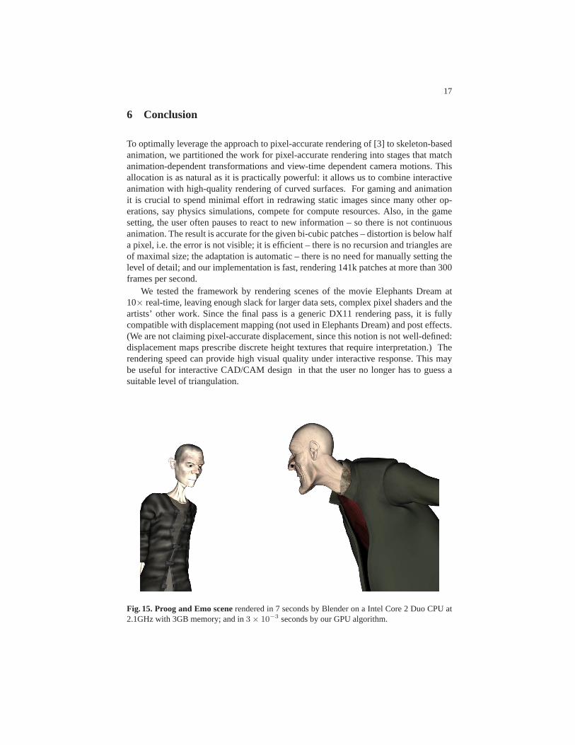
We tested the framework by rendering scenes of the movie Elephants Dream at10× real-time, leaving enough slack for larger data sets, complex pixel shaders and theartists’ other work. Since the final pass is a generic DX11 rendering pass, it is fullycompatible with displacement mapping (not used in Elephants Dream) and post effects.(We are not claiming pixel-accurate displacement, since this notion is not well-defined:displacement maps prescribe discrete height textures thatrequire interpretation.) Therendering speed can provide high visual quality under interactive response. This maybe useful for interactive CAD/CAM design in that the user no longer has to guess asuitable level of triangulation.
Fig. 15. Proog and Emo scenerendered in 7 seconds by Blender on a Intel Core 2 Duo CPU at2.1GHz with 3GB memory; and in3× 10−3 seconds by our GPU algorithm.
18
Acknowledgements
This work was supported in part by NSF Grant CCF-1117695. We thank the contribu-tors to Elephants Dream for creating this wonderful resource and the creators of SubD11to provide source code and model. Georg Umlauf’s insightfulquestion after the confer-ence presentation prompted the inclusion of the constantkm in the paragraph following(6).
References
1. T. DeRose, M. Kass, T. Truong, Subdivision surfaces in character animation, in: Proceedingsof the 25th annual conference on Computer graphics and interactive techniques, SIGGRAPH’98, ACM, New York, NY, USA, 1998, pp. 85–94.
2. J. Peters, U. Reif, Subdivision Surfaces, Vol. 3 of Geometry and Computing, Springer-Verlag,New York, 2008.
3. Y. I. Yeo, L. Bin, J. Peters, Efficient pixel-accurate rendering ofcurved surfaces, in: Proceed-ings of the ACM SIGGRAPH Symposium on Interactive 3D Graphics and Games, I3D ’12,ACM, New York, NY, USA, 2012, pp. 165–174.doi:10.1145/2159616.2159644.URL http://doi.acm.org/10.1145/2159616.2159644
4. Blender, Foundation, Elephants dream,http://orange.blender.org (2006).5. M. Fisher, K. Fatahalian, S. Boulos, K. Akeley, W. R. Mark, P. Hanrahan, DiagSplit: parallel,
crack-free, adaptive tessellation for micropolygon rendering, ACM Transactions on Graphics28 (5) (2009) 1–8.
6. M. Nießner, C. T. Loop, M. Meyer, T. DeRose, Feature-adaptiveGPU rendering of Catmull-Clark subdivision surfaces, ACM Trans. Graph 31 (1) (2012) 6.
7. D. Filip, R. Magedson, R. Markot, Surface algorithms using bounds on derivatives, ComputerAided Geometric Design 3 (4) (1986) 295–311.
8. M. Guthe, A. Balazs, R. Klein, GPU-based trimming and tessellation of NURBS and T-Spline surfaces, ACM Transactions on Graphics 24 (3) (2005) 1016–1023.
9. J. Hjelmervik, Hardware based visualization of b-spline surfaces, presentation, Eighth Inter-national Conference on Mathematical Methods for Curves and Surfaces Oslo, June 28 July3, 2012.
10. N. Magnenat-Thalmann, R. Laperriere, D. Thalmann, Joint–dependent local deformationsfor hand animation and object grasping, in: Graphics Interface ’88, 1988, pp. 26–33.
11. F. Cordier, N. Magnenat-Thalmann, A data-driven approach for real-time clothes simulation,Computer Graphics Forum 24 (2) (2005) 173–183.
12. L. Kavan, S. Collins, J. Zara, C. O’Sullivan, Geometric skinning with approximate dualquaternion blending, ACM Trans. Graph. 27 (2008) 105:1–105:23.
13. T. Ju, S. Schaefer, J. D. Warren, Mean value coordinates for closed triangular meshes, ACMTrans. Graph 24 (3) (2005) 561–566.
14. K. Zhou, X. Huang, W. Xu, B. Guo, H.-Y. Shum, Direct manipulation of subdivision surfaceson GPUs, ACM Trans. Graph 26 (3).
15. P. Joshi, M. Meyer, T. DeRose, B. Green, T. Sanocki, Harmoniccoordinates for characterarticulation, ACM Trans. Graph 26 (3) (2007) 71.
16. Y. Lipman, D. Levin, D. Cohen-Or, Green Coordinates, ACM Transactions on Graphics27 (3) (2008) 78:1–.
17. Blender, Foundation, Shape keys,http://wiki.blender.org/index.php/Doc:2.4/Manual/Animation/Techs/Shape/Shape_Keys.

19
18. A. Myles, T. Ni, J. Peters, Fast parallel construction of smooth surfaces from meshes withtri/quad/pent facets, Computer Graphics Forum 27 (5) (2008) 1365–1372.
19. Y. I. Yeo, T. Ni, A. Myles, V. Goel, J. Peters, Parallel smoothing ofquad meshes, The VisualComputer 25 (8) (2009) 757–769.
20. C. T. Loop, S. Schaefer, Approximating Catmull-Clark subdivisionsurfaces with bicubicpatches, ACM Trans. Graph 27 (1).
21. C. Loop, S. Schaefer, T. Ni, I. Castano, Approximating subdivision surfaces with Gregorypatches for hardware tessellation, ACM Trans. Graph. 28 (2009) 151:1–151:9.
22. J. Bolz, P. Schroder, Rapid evaluation of Catmull-Clark subdivision surfaces, in: Web3D ’02:Proceeding of the seventh international conference on 3D Web technology, ACM Press, NewYork, NY, USA, 2002, pp. 11–17.
23. M. Bunnell, GPU Gems 2: Programming Techniques for High-Performance Graphics andGeneral-Purpose Computation, Addison-Wesley, Reading, MA, 2005,Ch. 7. Adaptive Tes-sellation of Subdivision Surfaces with Displacement Mapping.
24. M. Nießner, C. T. Loop, G. Greiner, Efficient evaluation of semi-smooth creases in catmull-clark subdivision surfaces, 2012, p. 4.
25. MicroSoft, Subd11 sample (direct3d11),http://preview.library.microsoft.com/en-us/library/ee416576 (November 2008).
26. A. Vlachos, J. Peters, C. Boyd, J. L. Mitchell, Curved PN triangles,in: 2001, Symposium onInteractive 3D Graphics, Bi-Annual Conference Series, ACM Press, 2001, pp. 159–166.
27. I. Boier-Martin, D. Zorin, Differentiable parameterization of Catmull-Clark subdivision sur-faces, in: R. Scopigno, D. Zorin (Eds.), Symp. on Geom. Proc., Eurographics Assoc., Nice,France, 2004, pp. 159–168.
28. L. He, C. Loop, S. Schaefer, Improving the parameterization of approximate subdivisionsurfaces, in: C. Bregler, P. Sander, M. Wimmer (Eds.), Pacific Graphics, 2012, pp. xx–xx.
29. J. Peters, Mid-structures of subdividable linear efficient functionenclosures linking curvedand linear geometry, in: M. Lucian, M. Neamtu (Eds.), Proceedings ofSIAM conference,Seattle, Nov 2003, Nashboro, 2004.
30. D. Lutterkort, Envelopes of nonlinear geometry, Ph.D. thesis, Purdue University (Aug. 2000).31. D. Lutterkort, J. Peters, Tight linear bounds on the distance betweena spline and its B-spline
control polygon, Numerische Mathematik 89 (2001) 735–748.32. D. Lutterkort, J. Peters, Optimized refinable enclosures of multivariate polynomial pieces,
Computer Aided Geometric Design 18 (9) (2002) 851–863.33. J. Peters, X. Wu, On the optimality of piecewise linear max-norm enclosures based on slefes,
in: L. L. Schumaker (Ed.), Proc. Curves and Surfaces, St Malo 2002, Vanderbilt Press, 2003.34. X. Wu, J. Peters, Interference detection for subdivision surfaces, Computer Graphics Forum,
Eurographics 2004 23 (3) (2004) 577–585.35. X. Wu, J. Peters, An accurate error measure for adaptive subdivision surfaces, in: Proceed-
ings of The International Conference on Shape Modeling and Applications 2005, 2005, pp.51–57.
36. X. Wu, J. Peters, Sublime (subdividable linear maximum-norm enclosure) package,http://surflab.cise.ufl.edu/SubLiME.tar.gz, accessed Jan 2011 (2002).
37. R. L. Cook, L. Carpenter, E. Catmull, The Reyes image rendering architecture, in: M. C.Stone (Ed.), Computer Graphics (SIGGRAPH ’87 Proceedings), 1987, pp. 95–102.
38. K. Fatahalian, S. Boulos, J. Hegarty, K. Akeley, W. R. Mark, H. Moreton, P. Hanrahan,Reducing shading on GPUs using quad-fragment merging, ACM Trans. Graphics, 29(3),2010 (Proc. ACM SIGGRAPH 2010) 29 (4) (2010) 67:1–8.
39. K. Zhou, Q. Hou, Z. Ren, M. Gong, X. Sun, B. Guo, Renderants:interactive Reyes renderingon GPUs, ACM Trans. Graph 28 (5).