eec systems - 144.162.92.233144.162.92.233/faculty/mwhitten/presentations/2317/obd2.pdf · ford...
TRANSCRIPT
1
Ford Electronic Engine Controlsand On-Board Diagnostics II
Brookhaven College
EEC SystemsEEC I
1978 - emission and timing control
EEC II1979 - feedback carburetor
EEC III1980 - central fuel injection
EEC IV1983 - port fuel injection
EEC V1994 - 3.8L Mustang and 4.6L 2V Cougar/Thunderbird1995 - Continental, Crown Victoria/Grand Marquis, Ranger and Windstar
2
EEC I SystemInputs
BAROECTCKPEVPIATMAPTP
Electronic Control Assembly (ECA) and Calibration Assembly (CA)
OutputsEGRCEGRVIgnition TimingTAB
Operating StrategiesEGR ControlThermactor Air ControlIgnition Timing
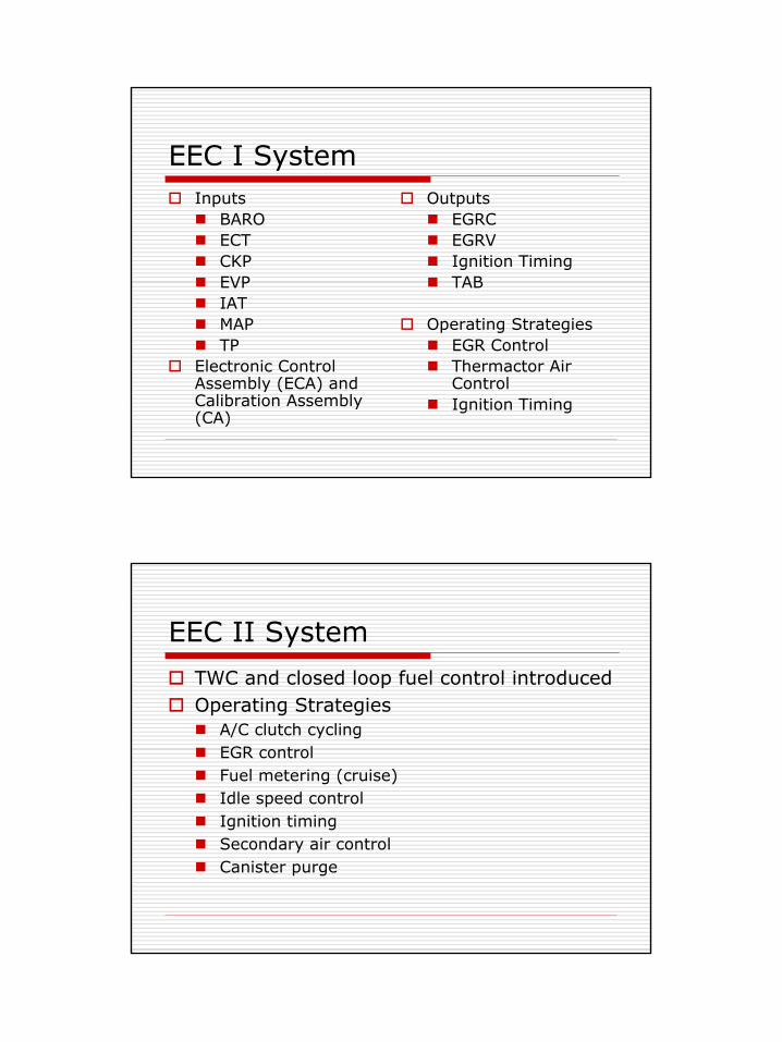
EEC II System
TWC and closed loop fuel control introducedOperating Strategies
A/C clutch cyclingEGR controlFuel metering (cruise)Idle speed controlIgnition timingSecondary air controlCanister purge
3
EEC II Inputs and OutputsInputs
ACCS - air conditioning cycling switchB/MAP - barometric/manifold absolute pressureCKP - crankshaft position sensorEVP - EGR valve position sensorECT - engine coolant sensorEGO - exhaust gas oxygen sensorTP - throttle position sensor
OutputsCANP - canister purge solenoidEGRC - exhaust gas recirculation control solenoidEGRV - exhaust gas recirculation vent solenoidFBCA - feedback carburetor actuatorSPARK - ignition controlTAB - thermactor air bypassTAD - thermactor air divertTKS - throttle kicker solenoidWAC - wide open throttle A/C clutch cutout
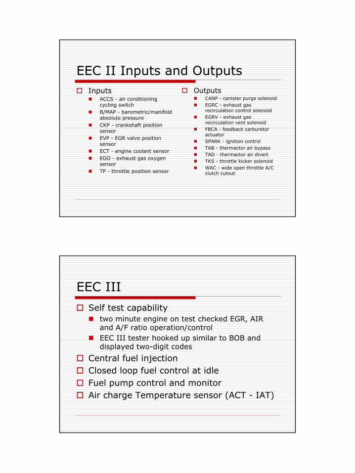
EEC III
Self test capabilitytwo minute engine on test checked EGR, AIR and A/F ratio operation/controlEEC III tester hooked up similar to BOB and displayed two-digit codes
Central fuel injectionClosed loop fuel control at idle Fuel pump control and monitorAir charge Temperature sensor (ACT - IAT)
4
EEC III StrategiesAC clutch cycling for engine loadClosed loop fuel controlFuel pump control and monitorEGRFuel metering
feedback carburetorcentral fuel injection (TBI)
Idle speed controlIgnition timingSecondary air injectionCanister Purge
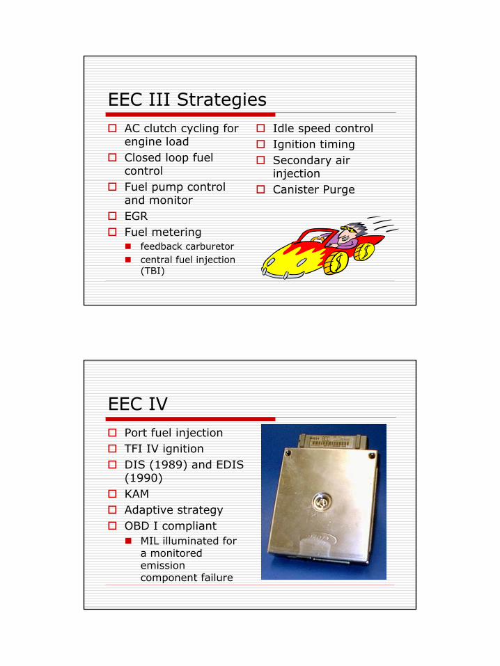
EEC IVPort fuel injectionTFI IV ignitionDIS (1989) and EDIS (1990)KAMAdaptive strategyOBD I compliant
MIL illuminated for a monitored emission component failure
5
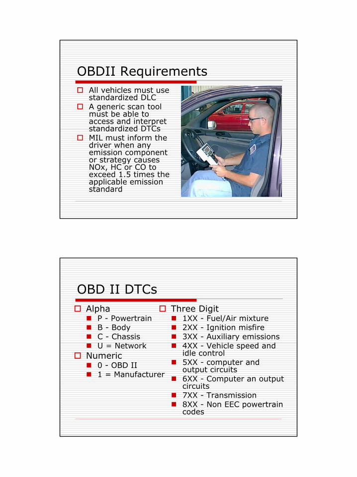
OBDII RequirementsAll vehicles must use standardized DLCA generic scan tool must be able to access and interpret standardized DTCsMIL must inform the driver when any emission component or strategy causes NOx, HC or CO to exceed 1.5 times the applicable emission standard
OBD II DTCsAlpha
P - PowertrainB - BodyC - ChassisU = Network
Numeric0 - OBD II1 = Manufacturer
Three Digit1XX - Fuel/Air mixture2XX - Ignition misfire3XX - Auxiliary emissions4XX - Vehicle speed and idle control5XX - computer and output circuits6XX - Computer an output circuits7XX - Transmission8XX - Non EEC powertrain codes
6
OBDII Drive CyclesWarm-up Cycle:
after an off cycle the engine temperature increases at least forty degrees Fahrenheit and reaches 160 degrees Fahrenheit
OBDII Drive Cycle: engine running, following an engine off period, during which the OBDII components are tested and the appropriate system monitors are completed (clears DTC P1000)
Monitors Comprehensive component monitor - continuousMisfire monitor - continuousFuel System monitor - continuousEGR monitor - a series of idles and accelerations required to completeHO2S monitor - 20 seconds at 20 to 45 MPH required to completeSecondary air monitor - closed loop idleCatalyst efficiency monitor - steady state monitorEVAP purge flow and vapor management monitorEVAP running loss system monitor
7
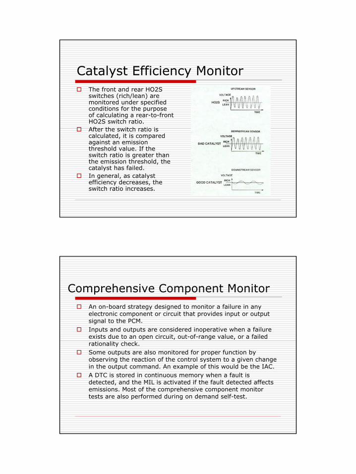
Catalyst Efficiency MonitorThe front and rear HO2S switches (rich/lean) are monitored under specified conditions for the purpose of calculating a rear-to-front HO2S switch ratio.After the switch ratio is calculated, it is compared against an emission threshold value. If the switch ratio is greater than the emission threshold, the catalyst has failed.In general, as catalyst efficiency decreases, the switch ratio increases.
Comprehensive Component MonitorAn on-board strategy designed to monitor a failure in any electronic component or circuit that provides input or output signal to the PCM. Inputs and outputs are considered inoperative when a failure exists due to an open circuit, out-of-range value, or a failed rationality check.Some outputs are also monitored for proper function by observing the reaction of the control system to a given change in the output command. An example of this would be the IAC.A DTC is stored in continuous memory when a fault is detected, and the MIL is activated if the fault detected affectsemissions. Most of the comprehensive component monitor tests are also performed during on demand self-test.
8
OBDII EVAP System
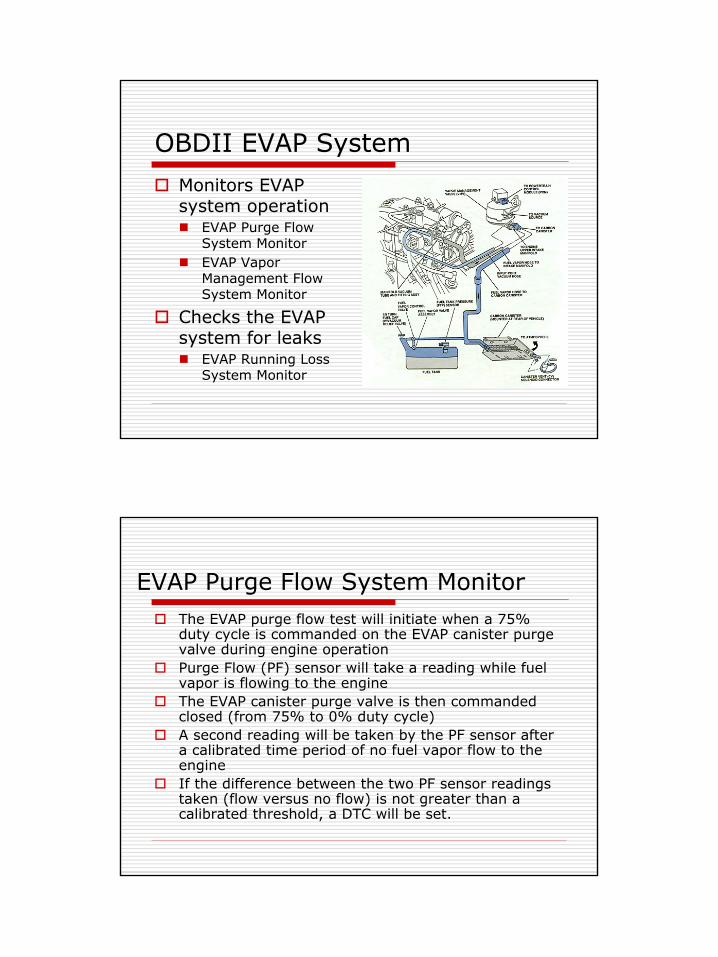
Monitors EVAP system operation
EVAP Purge Flow System MonitorEVAP Vapor Management Flow System Monitor
Checks the EVAP system for leaks
EVAP Running Loss System Monitor
EVAP Purge Flow System MonitorThe EVAP purge flow test will initiate when a 75% duty cycle is commanded on the EVAP canister purge valve during engine operation Purge Flow (PF) sensor will take a reading while fuel vapor is flowing to the engineThe EVAP canister purge valve is then commanded closed (from 75% to 0% duty cycle)A second reading will be taken by the PF sensor after a calibrated time period of no fuel vapor flow to the engineIf the difference between the two PF sensor readings taken (flow versus no flow) is not greater than a calibrated threshold, a DTC will be set.
9
EVAP Vapor Management Flow System Monitor
Before the flow test is performed, the PCM will calculate how much fuel vapor is present while purging under engine operation. If the amount of fuel vapor calculated is above a calibrated threshold,the idle speed portion of the EVAP vapor management flow test will be bypassed and the test will pass and complete.If the amount of fuel vapor calculated is below a calibrated threshold, the idle speed portion of the EVAP vapor management flow test must be executed to verify that the EVAP canister purge valve is functioning properly. The flow test will calculate the increase in the idle air requested by the PCM when the duty cycle on the EVAP canister purge valve is reduced from 75% to 0%.If the calculated increase in air flow exceeds a calibrated threshold, the PCM assumes the EVAP canister purge valve is functioning properly. If the calculated increase in air flow is negligible, the EVAP canister purge valve is not functioning properly and a DTC will be set.
EVAP Running Loss System Monitor
The canister vent (CV) solenoid is closed and the EVAP canister purge valve is operated at a minimum duty cycle of 75%. The fuel tank pressure (FTP) sensor monitors system pressureIf the target vacuum cannot be reached, a DTC will be set and the test will not be performed.After the target vacuum is reached, the purge valve is closed and the FTP monitors the EVAP system vacuum over time.If the allowable leakage is exceeded after three tests, a vapor generation check must be performed.
10
EVAP Running Loss System Monitor (cont.)
A vapor generation test is performed by closing the EVAP canister purge valve and opening the CV solenoid until atmospheric pressure is reached. The CV solenoid is then closed to seal the EVAP system.Fuel tank pressure build-up is monitored over a period of time to check for pressure build-up due to vapor generation. If the pressure build-up exceeds a specific value, the leak test results are invalid due to vapor generation and the system passes.If the fuel tank pressure build-up does not exceed the threshold, the leak test results are valid and a DTC will be set.
EGR System MonitorThe differential pressure feedback EGR (DPFE) sensor and circuitare continuously tested for opens and shorts. The EGR vacuum regulator solenoid is continuously tested for opens and shorts.The test for a stuck open EGR valve or EGR flow at idle is continuously performed whenever at idle. The monitor compares the DPFE circuit voltage at idle to the DPFE circuit voltage stored during KOEO.The DPFE sensor upstream hose is tested once per drive cycle fordisconnect and plugging. The PCM will momentarily command the EGR valve closed during acceleration. The monitor looks for the DPFE sensor voltage to be inconsistent for a no flow voltage. The EGR flow rate test is performed when engine speed and load are moderate and EGR vacuum regulator duty cycle is high. The monitor compares the actual DPFE circuit voltage to a desired EGR flow voltage.
11
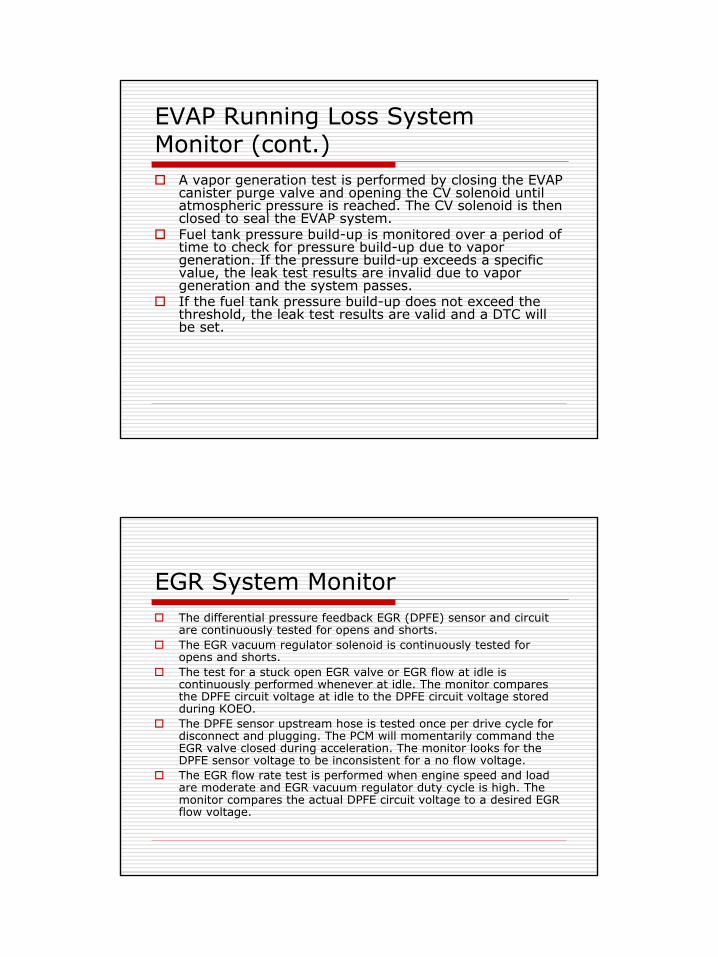
Fuel System MonitorThe HO2S detects the presence of oxygen in the exhaust and provides the PCM with feedback indicating air/fuel ratio.A correction factor is added to the fuel injector pulse-width calculation according to the Long and Short Term Fuel Trims as needed to compensate for variations in the fuel system.When the compensation exceeds a calibrated limit and the fuel trim table has clipped, the Fuel System Monitor sets a DTC.
HO2S MonitorA fixed frequency closed loop fuel control routine is executed and the upstream HO2S voltage amplitude and output response frequency are observed.A HO2S heater circuit fault is determined by turning the heater on and off and looking for a corresponding change in the Output State Monitor and by measuring the current going through the heater circuit.
12
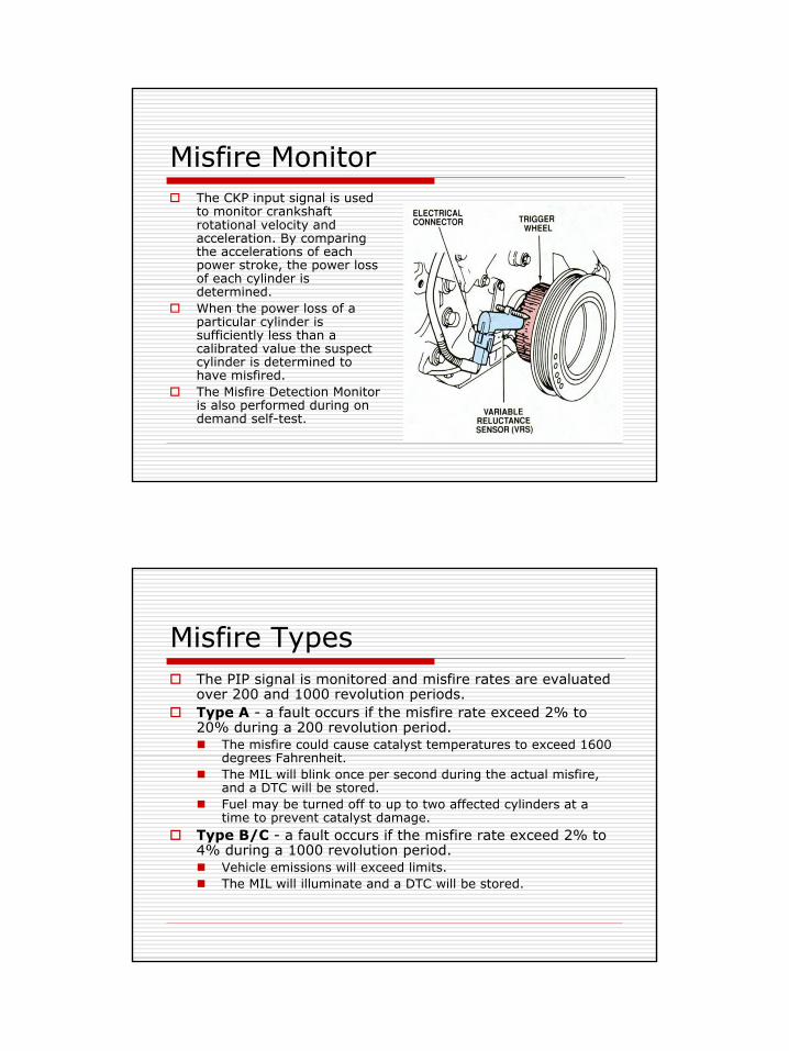
Misfire MonitorThe CKP input signal is used to monitor crankshaft rotational velocity and acceleration. By comparing the accelerations of each power stroke, the power loss of each cylinder is determined. When the power loss of a particular cylinder is sufficiently less than a calibrated value the suspect cylinder is determined to have misfired.The Misfire Detection Monitor is also performed during on demand self-test.
Misfire TypesThe PIP signal is monitored and misfire rates are evaluated over 200 and 1000 revolution periods.Type A - a fault occurs if the misfire rate exceed 2% to 20% during a 200 revolution period.
The misfire could cause catalyst temperatures to exceed 1600 degrees Fahrenheit.The MIL will blink once per second during the actual misfire, and a DTC will be stored.Fuel may be turned off to up to two affected cylinders at a time to prevent catalyst damage.
Type B/C - a fault occurs if the misfire rate exceed 2% to 4% during a 1000 revolution period.
Vehicle emissions will exceed limits.The MIL will illuminate and a DTC will be stored.
13
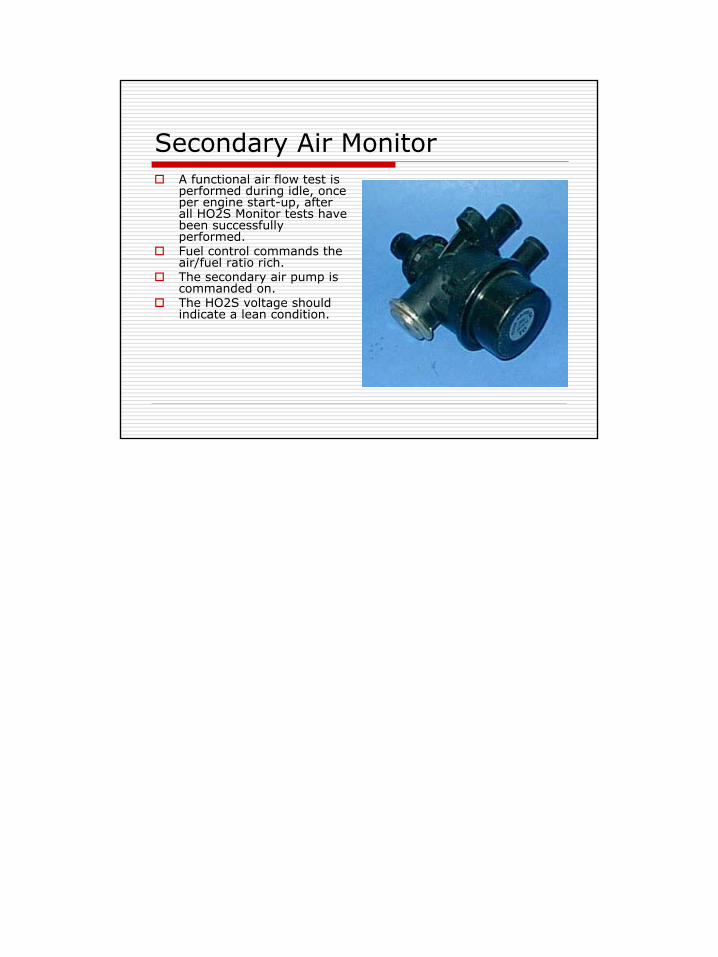
Secondary Air MonitorA functional air flow test is performed during idle, once per engine start-up, after all HO2S Monitor tests have been successfully performed. Fuel control commands the air/fuel ratio rich.The secondary air pump is commanded on.The HO2S voltage should indicate a lean condition.