editor laura. 1 outotec customer ... · pdf fileoperate above the allowable speed the...
TRANSCRIPT

1
OUTOTEC CUSTOMER eNEWSLETTER 2/2017
Editor: Laura White, [email protected]
SOUTH EAST ASIA PACIFIC
CONTENTS• Flotation inefficiencies - 5 key areas, page 1• Building a solid foundation for your mill, page 4• Case study: Nui Phao flotation upgrade, page 7• Business and product news, page 11• Case study: Fosterville Gold Mine - BIOX, page 13
2/2017
In this two-part article we look at inexpensive ways to investigate float inefficiencies in your circuit. Part 1 in our May edition covered laboratory testing. Part 2 now looks at the next steps to reviewing your flotation inefficiencies. This article will show you five key checks to help ensure you make the right decisions.
Five key areas to investigate
1. Do you have enough residence time?Do you have enough residence time - i.e. flotation volume - in the circuit? Many established processing plants designed for a certain type of ore are now treating different material. You may find, for example, that your current ore requires more residence time to achieve the same recovery target as before. If the required residence time increase is small, you can try and operate the plant at a higher feed density, however there are limits. You can also try and alternate the direction of the shaft in adjacent cells to reduce short circuiting. If the float cell has sanding you should reduce this, as it will increase the available tank volume for flotation. The last resort, and the most capital-intense option, would be to install additional float cells.
2. Are you achieving good slurry mixing?Good slurry dispersion increases the probability of recovery by flotation, especially for coarser particles. Here are some solutions to increase slurry dispersion.
FLOTATION INEFFICIENCIES - 5 KEY AREAS TO CHECK
Firstly, review the air flow rate settings. In some flotation mechanism designs, the air and slurry pumping chamber is combined. Thus, high air flow rates fills the chamber and lowers the pumping efficiency. Note there are limits, reducing the air too much will adversely affect recovery. It can be difficult sometimes to find the optimum and it is usually a trial and error approach.
Secondly, you can increase the rotor or impeller tip speed through a pulley change or change in the VSD settings. Make sure not to create too much turbulence within the cell, if the froth at the top of the cell starts to move in a circular direction, producing a wave, then reduce the rotor tip speed. When the froth has a wave, it is very difficult to maintain product grade.
Another option is look at installing vertical tank baffels. This helps mixing and reduces the dead zones and possible sanding. It can especially help with slurry mixing in larger cells ≥ 50m3. As a last resort, investigate changing the mechanism to another design that promotes better slurry mixing.
You should be aware that increasing the rotor / impeller tip speed will also increase the power draw and the mechanism wear life. It is highly recommended that before increasing the rotor speed, check with your equipment supplier that the installed motor is suitable, i.e. power draw with and without air.

Outotec SEAP Customer eNewsletter 2/2017 2
The supplier may advise you to start the float cell with the air on to prevent the motor from tripping. The other thing the equipment supplier should check is that the increase in speed is not close to the maximum allowable speed. If you operate above the allowable speed the mechanical integrity of the internal components may be affected and this could result in a major equipment failure. The other area to take note is the wear life of the mechanism. This will decrease as you increase the rotor speed. Depending on the abrasiveness of the ore, the benefits of the increased rotor speed may be offset by the added spare parts and maintenance cost.
3. Do you have good froth mobility?Usually you can tell by looking at the froth. Is it sticky and collapsing or does it look barren with no metal on the surface? To understand why this is happening it is recommended that you take timed concentrate lip samples. The froth surface open area for a particular cell can be obtained from a supplier. This information can then be used to calculate the froth carry rate (FCR). You should have guide ranges for your cells depending on the duty and there is also different ranges for some commodities such as coal. Generally if you are outside the range, then the likely solution may be a different froth crowder. If you are within the range, then the likely solution is to review your process control strategy and or install some froth cameras.
Froth crowding can be used to lower mass pulls and in some cases our clients have justified froth crowding purely on frother savings. In one particular case, the froth surface area was too large for the metal available and the client had to use high amounts of frother to maintain a stable froth. By reducing the froth surface, the frother dosage was halved and the metal recovery remained the same.
Another possible solution is to use froth cameras to control froth mobility. Froth cameras are very useful for operations with changing feed conditions. Typically, sites without cameras will try and control the froth mobility through pulp level or air flow rate changes. This can be extremely difficult for changing ore feed conditions because these settings need to be adjusted continuously.
If there is an on-line analyser, whether it’s grade or particle size distribution, you can also use these values to adjust the set points based on the incoming feed conditions. Note, froth velocity control in rougher circuits mainly target recovery improvement, while froth cameras in cleaner circuits mainly target concentrate grade control. There is a direct correlation between froth velocity and concentrate grade.
4. How’s your air dispersion?Air dispersion directly affects recovery. Air dispersion is controlled by the blower and the flotation mechanism. Bubbles distributed into the bottom of the cell need to be a certain size to provide sufficient surface area for particle attachment and to ensure that they are transported to the froth. In extreme cases you can observe poor air dispersion by burping in the cell, but in most cases it will be hard to detect.
To investigate further, you will need to conduct gas dispersion measurements using a device like the Anglo Platinum Bubble Sizer (APBS). The two main measurements of interest is the Jg (air flow rate within the cell) and the bubble size distribution.
The Jg value is useful because you can compare it to similar operations and determine whether you have sufficient air in your circuit. The information can also be used to check the flow rate metre reading and confirm if the instrument has been calibrated correctly.
The second measurement, bubble size distribution, tells you whether the mechanism is working correctly i.e. no air slot blockages. It also tells you whether the frother type and dosage is correct. Remember, the frother addition controls bubble size.
5. Finally, process control There are many process control options available. In order to check that your process control is working correctly, conduct the following exercise. Make set point changes to the air level within your normal operating range and observe how long it takes for measured value to reach the set point. Some strategies to improve your set point control would start with P&I parameter tuning.
Concentrate lip sampler - measuring tph for the calculation of FCR.
Measuring Jg & bubble size distribution with the APBS instrument.

Outotec SEAP Customer eNewsletter 2/2017 3
Ensuring the circuit is stable and operating under normal conditions before beginning. Also check the calibration of the instrumentation and look to update your instru-ments where required. For example, you want to go from a manual/auto discharge valve arrangement to a fully auto discharge valve. You may also want to add more instrumen-tation such as density gauges or an on-stream analyser. Another option is to investigate a smart process control package.
Next steps for flotation profitabilityAt this point you have completed your investigation and pin pointed the problem area. The next step is to understand what solutions are available, how they can be implemented and how much they will cost. A change to the process equipment is not always the best solution.
Working together with your supplier, you should take a very considered approach before investing capital. If the results from the diagnostic testing indicate an upgrade is required, conduct (where possible) simulation testing to further quantify the benefits. This will assist with the commercial justification.
Finally, develop and implement the solution together with the supplier to ensure the best outcome is achieved.
FOR FURTHER INFORMATION PLEASE CONTACT:
To listen to full webinar visit www.outotec.com/webinars

Outotec SEAP Customer eNewsletter 2/2017 4
BUILDING A SOLID FOUNDATION FOR YOUR MILLThe grinding mill is at the heart of a mining operation, but a poorly designed or constructed foundation will not only affect grinding mill performance but potentially render the mill out of action – thereby costing millions of dollars in lost production.
The following advice will help ensure the foundation is right before you install a new mill.
Foundation load specificationIt is the responsibility of the mill supplier to specify the mill related loads. These loads are then used by theengineer responsible for designing the mill foundation. Mill loading diagrams are inherently complicatedbut most reputable mill suppliers will ensure the diagrams are comprehensive enough to include allnecessary information but are still as unambiguous and straightforward as possible. For example, somemill suppliers do not state the dynamic loads generated by an operating mill, ie drive train and chargerelated load variations. Such a document may be far simpler to comprehend, however will cause problemswhen it comes to correctly designing the foundation. Consideration of static x, y, z loads is not enough; capacity to accept the dynamic loads while achieving acceptable vibration levels must also be designed into any mill foundation.
Designing the foundationsA reputable mill supplier will also provide a diagrammatic
foundation layout, which can be used alongsidethe loading diagram and gives the foundation engineer a truly comprehensive picture. This layout diagramshould not be mistaken for a fully designed solution; there have been cases where this layout was copiedand used, as provided, for the installed foundation arrangement. The supplied diagram can help ensure thefoundations suit the mill and do not clash with rotating parts – but there is more work to be done by thefoundation engineer...
Some factors the engineer should consider include:
1. Mill supplier data Loadings and directions of loadings are easy to misinterpret, especially in dual pinion mills where one pinion experiences a downward load and the other experiences uplift. Such loadings must be carefully noted, along with critical items such as boundary constraints, displacement and vibration limits
2. Local conditions Small inaccuracies in strata data can dramatically compromise mill performance, so ensure the data is right. It is also important to perform sensitivity analyses and design-out any potential conflicts. In general, local concrete design standards should be applied, particularly in relation to seismic requirements, and consideration should be given to the quality of the materials being used. The capacity of the concrete needs to be carefully considered as not all concrete and reinforcing bars are the same quality!

Outotec SEAP Customer eNewsletter 2/2017 5
3. Outside influencesVibrations from other equipment, and adjacent mills in particular, can accumulate to detrimental effect. Adjacent mills of the same size and speed are particularly prone to generating vibration issues for each other. Installing adjacent mills on separate slabs is not always enough to avert problems. Other structures directly connected to the mill must also be considered and should be included in the mill model. Natural frequencies must also be considered and alignment of the foundation’s natural frequency with the dominant frequencies of the mill operation must be studied and avoided.
The construction phase should be planned so that installation and ongoing maintenance access is considered, and the service line access (ie power, instrumentation and lubrication) isappropriately placed. If service line block outs are omitted or unsuitably placed, it can necessitate expensive core drilling or compromise installation runs.
Constructing the foundationsThe mill foundation is often the largest monolithic concrete structure on a mine site - and it is also the element most likely to bring a concrete contractor unstuck. Following are some key tips to help reduce foundation construction risk, but there are many areas in which concrete construction can go wrong, so choosing a quality contractor is crucial.
The contractor must appoint an experienced team and work with a licensed surveyor. It is also advisable that a plant manager employs a civil construction manager, independent of the contractor, to oversee the work. Without scrutiny, issues can be literally covered over.
1. Pre-pour Ensuring correctness of cast-ins is a given, as poorly arranged cast-ins can cause problems such as base plate instability. As a result of a poor cast-in box design, the washers for the hold down bolts in
the photo above were located partly on a steel open section and partly on a steel plate - some 8mm difference in elevation. This error resulted in a hold down bolt that could never be kept tight and led to pinion bearing base plate instability.
Just as important is the proper location of the cast-ins within the reinforcing so as to ensure they do not move during the concrete pour. Core drilling is sometimes needed to correct misalignment, so it’s worth getting this right! It is also important to avoid any air pockets under or around the cast-ins during the pour.
Likewise, be sure reinforcing is properly installed. Once it is covered by concrete it is virtually impossible to check. Reinforcing must encapsulate base plate shear keys and go all the way to the top of the concrete. Block out profiles should follow the shape of the shear key, leaving 50mm of clearance for later grouting.
Make sure the reinforcing is not too close to the concrete surface. If there is a loss of cover exposing reinforcing to the surface, or if the concrete is allowed to absorb fluids that will corrode the reinforcing,concrete cancer will result.
Misalignment between mill bearing retaining bolt hole and cast-in.
Incorrect foundation bolt installation with uneven washer support

Outotec SEAP Customer eNewsletter 2/2017 6
The above picture shows a badly leveled jacking plate which needs to be removed and reset. As concrete is very dense, a large buoyancy induced force can be generated during the pour that acts against the cast-ins. Vibration of the poured concrete only makes this force higher. The cast-ins must be very securely fastened pre-pour such that the ultimate location of the cast-in is the intended location and not displaced by the buoyancy induced forces.
2. During the pour Large concreting jobs are generally done in stages – but delays between pours can make it difficult to get a good bond between concrete layers, resulting in a ‘dry joint’ which can lead to serious cracking. A dry joint can allow the concrete section above the joint to move somewhat independently to that below the joint. Once this independence is established, the vibration of the mill equipment connected to the independent foundation quickly increases beyond acceptable levels.
If there is the potential of a dry joint due to the pouring process, there are ways of achieving a good bond between the already-poured concrete and the new pour. The responsible engineer should determine which methods are acceptable.
3. Finishing the foundation The completed foundation needs to be properly grouted so choose the right grout for the job, ensure the concrete is properly scabbled in preparation, and fit hold down bolts with sleeves to allow tightening stretch.
Only the underside of the base plates should be grouted and it is important to ensure there are no air pockets underneath. Chamfer the grout edges away from the base plate to encourage water dissipation. Base plate grouting should be an integral part of the installation specification.
If there are any process solutions on site which could degrade the concrete over time, the concrete must be sealed. This sealant may take the form of a simple epoxy coating to a more sophisticated vinyl ester resin; the choice depends on the type of process solutions liable to come into contact with the foundation.
Misaligned jacking plate set in concrete, this should be horizontal.
ConclusionProducing a good foundation takes attention to detail in the planning, design and construction phases. If the foundation engineer or installer is ever in doubt regarding specific issues, the most important advice is to seek advice. A competent mill supplier will, at the very least, point you in the right direction. Careful management of those phases will ensure your mill is built on a solid, high quality foundation, thereby avoiding any unnecessary, costly problems.
A close-up of a dry joint.
FOR FURTHER INFORMATION PLEASE CONTACT:
Outotec SEAP Customer eNewsletter 2/2017 7
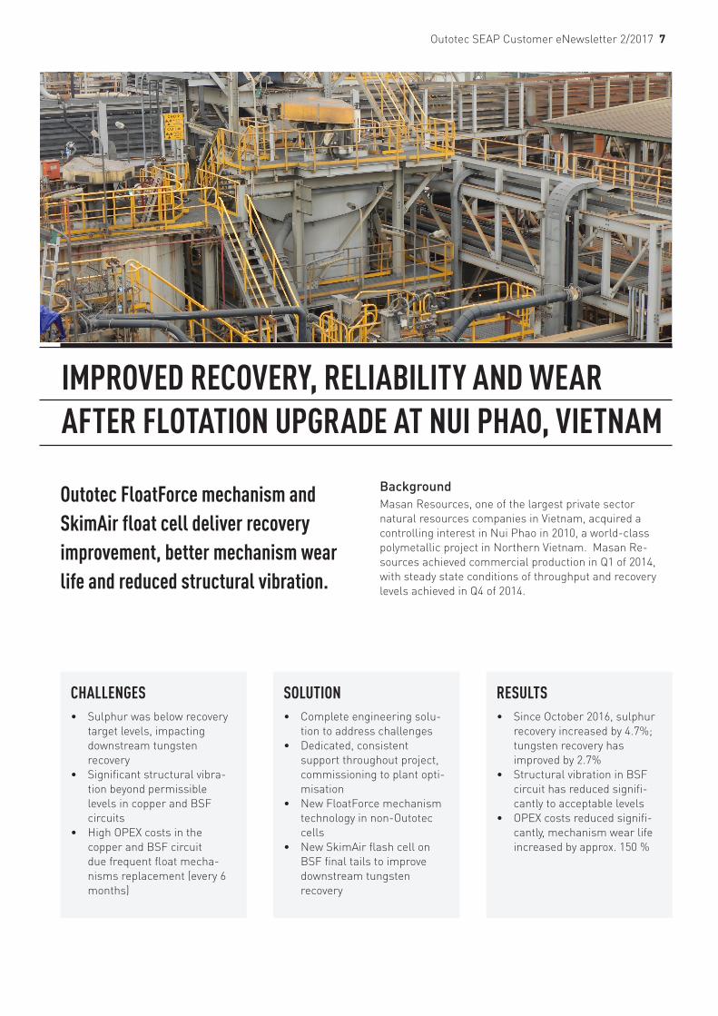
Outotec FloatForce mechanism and SkimAir float cell deliver recovery improvement, better mechanism wear life and reduced structural vibration.
Background Masan Resources, one of the largest private sector natural resources companies in Vietnam, acquired a controlling interest in Nui Phao in 2010, a world-class polymetallic project in Northern Vietnam. Masan Re-sources achieved commercial production in Q1 of 2014, with steady state conditions of throughput and recovery levels achieved in Q4 of 2014.
CHALLENGES• Sulphur was below recovery
target levels, impacting downstream tungsten recovery
• Significant structural vibra-tion beyond permissible levels in copper and BSF circuits
• High OPEX costs in the copper and BSF circuit due frequent float mecha-nisms replacement (every 6 months)
SOLUTION • Complete engineering solu-
tion to address challenges• Dedicated, consistent
support throughout project, commissioning to plant opti-misation
• New FloatForce mechanism technology in non-Outotec cells
• New SkimAir flash cell on BSF final tails to improve downstream tungsten recovery
RESULTS• Since October 2016, sulphur
recovery increased by 4.7%; tungsten recovery has improved by 2.7%
• Structural vibration in BSF circuit has reduced signifi-cantly to acceptable levels
• OPEX costs reduced signifi-cantly, mechanism wear life increased by approx. 150 %
IMPROVED RECOVERY, RELIABILITY AND WEAR AFTER FLOTATION UPGRADE AT NUI PHAO, VIETNAM

Outotec SEAP Customer eNewsletter 2/2017 8
Nui Phao is now the largest producer of tungsten outside China, and amongst the largest producers of acid-grade fluorspar and bismuth in the world. Masan Resources undertook various projects to improve operational profita-bility at Nui Phao, but the copper and bulk sulfide flotation (BSF) rougher circuits still experienced inefficiencies.
Since commissioning, Nui Phao’s metallurgical perfor-mance of the copper and BSF roughers was below expec-tations. In March 2013, the sulphur grade in the BSF tails was 3.5% S (on average), significantly higher than the design value of <1.5% S. The higher sulfur tails grades effects the downstream performance of the tungsten gravity plant. Coarse sulphur competes with tungsten in the gravity plant, and both tungsten grade and recovery suffers. The lower sulfur recoveries (particularly in the coarse +106 µm range) were attributed to insufficient flotation capacity and poor particle suspension (striation) in the flotation cells.
Nui Phao undertook various remedial steps and the BSF tails reduced to 2.5% S. However, the copper and BSF circuit experienced significant structural and mechanical vibration and reduced mechanism wear life. Short-term solutions were implemented but it was recognised that a longer-term solution was required.
Outotec scopeIn 2015, NMPC approached Outotec to investigate opti-mising recovery in the copper and BSF circuits, as well as reducing structural vibrations and improving mechanism wear life. Outotec also investigated options to increase the sulphide minerals recovery from the BSF rougher tails stream. Mineralogy reports indicated that there were still significant coarse sulphide particles recoverable by flota-tion to warrant further investigation. The objective was to achieve a BSF tails grade (feed to tungsten gravity circuit) of ≤1.5% S.
FloatForce upgradeAfter reviewing the existing copper and BSF circuit, Outotec recommended replacing the internal components of the Metso cells with the FloatForce mechanism. In the Metso mechanism design, the stator is suspended from the lower shaft, and this arrangement was identified as the cause of the mechanical and structural vibration. The FloatForce stator design is bolted to the tank floor and was predicted to deliver significant reduction in circuit vibration. It was expected that metallurgical performance would be unaffected by the mechanism change
In October 2015, a FloatForce trial upgrade was under-taken on one Metso cell, resulting in significantly lower
Outotec SkimAir installation at Nui Phao Mining Company.
Fig 1. Vibration survey results (before and after FloatForce upgrade)

Outotec SEAP Customer eNewsletter 2/2017 9
vibration, with no adverse metallurgical performance. In March 2016, during a 3-day shutdown, all remaining copper and BSF rougher cells were upgraded with Float-Force mechanismsm (plus new bearing assemblies with drive shafts).
Structural improvementThe FloatForce mechanism significantly reduced the structural and mechanical vibration, see figure 1. Previ-ously in the copper and BSF circuit, the 12 points surveyed indicated that the structural vibration ranged between 6 and 17 mm/s. Seven points were above the permissible level. After the conversion to FloatForce, all 12 points indicated a structural vibration <4mm/s and were within acceptable levels.
OPEX cost savingThe FloatForce mechanism significantly improved the mechanism wear life. Previously in the copper and BSF circuit, all flotation rotor and stator units in this circuit were replaced every six months. This resulted in a signifi-cant operational cost in spare parts and labour. Following the conversion to FloatForce the mechanism wear life has increased from 6 to 15 months. The FloatForce mechanism is operating at a similar rotor tip speed to the previous design. Metallurgical performanceAfter the conversion to FloatForce, the BSF rougher circuit initially experienced poor particle suspension affecting sulphur mineral recovery. Outotec worked closely with Nui Phao to improve performance. By October 2016, all recommended changes (including FlowBooster- secondary impeller, vertical baffles, froth stabilising fins) were implemented. The BSF rougher tails grade returned to the target value of <2.5% S.
SkimAir Flash flotation cellFlash flotation (SkimAir SK500) was also investigated by Outotec as part of the BSF upgrade. The objective was to increase the recovery of liberated coarse (+106 µm) sulphur minerals and lower the BSF tails further from <2.5% S to ≤1.5% S.
-16%
-11%
-6%
-1%
4%
9%
14%
Oct-15 Nov-15 Dec-15 Jan-16 Feb-16 Mar-16 Apr-16 May-16 Jun-16 Jul-16 Aug-16 Sep-16 Oct-16 Nov-16 Dec-16 Jan-17 Feb-17
Tung
sten R
ecove
ry (%
)
Tungsten Circuit Recovery 2 per. Mov. Avg. (Tungsten Circuit Recovery)
March 2016a> Flash Cell installedb> Copper and BSF Mechanism converted
July 2016Flash Cell double internal froth launder installed
October 2016New Flowbooster installed in Copper and BSF circuits
Fig 2. Tungsten circuit recovery (based on monthly averages).
The justification for flash over conventional flotation was based on the ALS mineralogy findings. The coarse sulphide minerals in the tails were predominately liber-ated or rich in binary associations. Thus, under the optimum flotation conditions, it was expected that rela-tively short residence times would be required to achieve additional sulphur recovery.
In May 2015, Outotec conducted laboratory flash flotation test work at Nui Phao, followed by NPMC’s own pilot plant trial. The plant trial indicated a sulphur unit recovery of 54% (on average) at a sulphur grade of 27% S, which was consistent with Outotec performance guarantees, so the full-scale flash circuit was installed. The BSF rougher tails was pumped to a new cyclone cluster and the cyclone underflow was fed to the Outotec flash cell. The flash concentrate was sent to concentrate thickener, whilst the flash tails combined with the cyclone overflow and was pumped to the tungsten gravity circuit. It was noted that the Nui Phao flash circuit would be unique, as normally flash cells are located in the communition circuit.
Metallurgical improvementDuring the first few weeks of the flash cell operation, the metallurgical results were significantly below expec-tations. Flash survey results in April 2016 indicated a sulphur unit recovery of only 30% (on average), lower than the predicted sulfur recovery of 50 – 60%.
Outotec attended site and observed that the froth velocity to the concentrate launder was lower than ideal. Sizing results confirmed poor coarse sulphur recovery, when compared to the finer size fractions. There was a sharp drop off in coarse particle recovery, which is not typical of flash circuits.
Optimising Flash flotationTo improve performance, Outotec recommended a new double internal concentrate launder with a larger froth cone, to reduce the FSA (Froth Surface Area) and increase the FCR (Froth Carry Rate) to its optimal rate. In July 2016, the new concentrate launder was installed and the improvement in sulphur recovery was immediate.
Outotec SEAP Customer eNewsletter 2/2017 10
At a feed density of 1.52 S.G, the flash sulphur unit recovery increased to 55%. The -180 +150 µm size fraction sulphur recovery was ~70%, and comparable to the finer size frac-tions. The results confirmed that the new froth launder had been successful in improving coarse sulphur mineral recovery. As a consequence, the BSF final tails grade reduced to the target value of ≤1.5% S.
Figure 2 presents the CUSUM chart for the tungsten circuit recovery (based on the monthly averages), indicating a tung-sten recovery improvement since March 2016. It is impor-tant to note that from April to October 2016, the tungsten circuit underwent other optimisation projects, resulting in increased tungsten recovery by 4.5%. Since October 2016, the BSF circuit upgrades has improved the tungsten recovery by a further 2.7%.
SummaryThe Outotec FloatForce mechanism in the existing copper and BSF rougher circuits, combined with the new flash flotation (SkimAir SK500) circuit, have achieved the metal-lurgical recovery improvement targets at Nui Phao. The recovery of the coarse rich sulphur particles has resulted in an improved sulphur recovery. The overall sulphur mineral recovery has increased by 4.7% and has produced the desired improvements in the tungsten gravity circuit. Since October 2016, the tungsten recovery has increased by 2.7%.
In addition, the Outotec FloatForce mechanism design, operating at similar impeller tip speeds to previous, has achieved the desired operational benefits. The structural vibration has reduced to acceptable levels (< 4.0 mm/s) and the OPEX costs have also reduced, with mechanism wear life increased by 150%. Based on the metallurgical and operational benefits, the BSF circuit upgrades achieved the project objectives and no further technology upgrades are required in this area.
The overall sulphur mineral recovery has increased by 4.7% and has produced the desired improvements in the tungsten gravity circuit. Since October 2016, the tungsten recovery has increased by 2.7%.
FOR FURTHER INFORMATION PLEASE CONTACT:

11 Outotec SEAP Customer eNewsletter 2/2017
COPPER SMELTER SHUTDOWN SERVICES IN SOUTH AMERICAOutotec has been awarded a contract for shutdown services to a copper smelter in South America.
Outotec’s scope of work includes the demolition and reconstruction of a smelting furnace originally designed and delivered by Outotec. The service will be delivered during the third quarter of 2017.
“This order demonstrates our commitment to deliv-ering life-cycle solutions to our customers. After the initial technology transfer we are able to maintain, upgrade and service the plant during its entire life-time to maximize plant productivity”, says Markku Teräsvasara, President of Outotec and acting head of the Services business unit.
More information is available here....
PROCESS EQUIPMENT AND SERVICES TO A GOLD PROJECT IN WEST AFRICAOutotec has been awarded a contract for the delivery of process equipment and services to a greenfield gold project in West Africa.
Outotec’s scope of work includes the design and delivery of a 6 MW SAG mill, a 6 MW ball mill, a pre-leach thickener and a comprehensive service package including spare parts and tooling and instal-lation equipment. The equipment will be delivered during the second quarter of 2018.
More information is available here....
OUTOTEC ACHIEVED ECOVADIS GOLD RATING IN SUPPLIER CSR ASSESSMENT Outotec has achieved EcoVadis Gold certification for its corporate responsibility practices and ranked in the top 5% of suppliers in its field. EcoVadis operates an international platform to assess the corporate social responsibility (CSR) of suppliers in respect to environment, labor practices, ethics and sustainable procurement.
Outotec reports its corporate responsibility using the Global Reporting Initiative (GRI) standards, is committed to the UN Global Compact initiative and the most relevant UN Sustainable Develop-ment Goals as defined by the company. For several years, Outotec has been included in the Global 100 index of the world’s most sustainable companies. Outotec’s sustainability report is available at www.outotec.com.
EcoVadis has assessed over 30,000 companies from 150 sectors and 110 countries. Its methodology and criteria used are in line with international CSR standards including the Global Reporting Initiative (GRI), UN Global Compact, and ISO 26000.
More information is available here....

Outotec SEAP Customer eNewsletter 2/2017 12
MINERALS PROCESSING TECHNOLOGY AND SERVICES TO MMC NORILSK NICKEL IN RUSSIAOutotec has been awarded a contract by MMC Norilsk Nickel for the delivery of minerals processing technology and related advisory services to Kola Mining and Metallurgical Company’s concentrator plant in Zapolyarny, Pechenga District in Russia.
Kola MMC produces annually 383,000 tonnes of nickel concentrate in Zapolyarny. Outotec’s scope includes engineering, the delivery of filtration, thickening, flotation and analyzer equipment, as well as training and site services. The deliv-eries will take place at the end of 2018.
“Our delivery supports Norilsk Nickel’s target to improve the environmental performance of the Zapolyarny operations. Outotec’s dewatering, flotation and analyzer solutions are designed for efficient and environmentally sound production of nickel and copper concentrates”, says Kimmo Kontola, head of Outotec’s Minerals Processing business unit.
More information is available here....
LITHIUM TECHNOLOGY TO SOUTH AMERICAOutotec has been awarded an order for the delivery of technology and process equipment for a lithium carbonate plant in South America.
Salt lake brine and spodumene ore are the primary sources for lithium. Outotec offers sustainable solutions both for processing lithium from brines and for the entire value chain of processing spodumene ore to lithium carbonate, including ore beneficiation, calcination, and both acid and alkaline hydrometallurgical refining.
Outotec’s scope in this order includes technology to remove impurities from salt lake brine, detail engineering, project management, delivery of proprietary process equipment such as filters, clarifier and reactors, as well as other equip-ment and technical assistance.
“This order reflects the increased demand of lithium processing solutions due to rapidly expanding markets for lithium salts. With our broad expertise and in-house R&D and raw material testing facilities we are well positioned in this growth market”, says Kalle Härkki, head of Outotec’s Metals, Energy & Water business.
More information is available here....
TECHNICAL SEMINAR - NOVEMBER 2017
Our series of technical seminars continue to prove very popular! These seminars are complimentary, providing information on all facets of a technology – from general overview and theory, to in-depth discussion of operation, control, applications and innovations.
We have an upcoming technical seminar in November for our Philippines customers.
Minerals processing technical seminar - Baguio, Monday 20 November, 2017• Comminution circuit optimisation, flotation, dewatering solutions and water treatment.
If you would like to attend, or require more information, please contact [email protected].
COMPLIMENTARY SEMINARCOUNTS TOWARDS PROFESSIONAL
DEVELOPMENT HOURS!

Outotec SEAP Customer eNewsletter 2/2017 13
ROBUST, LOW-COST BIOX PROCESS AT FOSTERVILLE GOLD MINE, AUSTRALIA
A robust, efficient and environmentally friendly process to economically treat the refractory Fosterville gold ore.Kirkland Lake Gold is a mid-tier gold producer targeting ~530,000 – 570,000 ounces in Tier 1 mining jurisdictions of Canada and Australia. The production profile of the Company is anchored by three high-grade, low-cost oper-ations, the Macassa Mine and the Taylor Mine, located in North-eastern Ontario, and the Fosterville Mine located in the state of Victoria, Australia. Kirkland Lake Gold’s
solid base of quality assets is complemented by district scale exploration potential, supported by a strong finan-cial position with extensive management and operational expertise.
Kirkland Lake Gold acquired the Fosterville Gold Mine through the business combination with Newmarket Gold, which was completed on November 30, 2016.
Fosterville MineThe Fosterville Mine is a high-grade, low cost under-ground gold mine, located 20km from the town of Bendigo, Australia. It is the largest gold producer in the state of Victoria, Australia. The Fosterville Mine features
CHALLENGES
• Refractory gold ore, yielding low (<10 %) gold recovery on direct cyanidation
• High level of sulphide oxida-tion to achieve commercially acceptable gold recovery
• Environmentally sensitive location for construction and operation of the plant
SOLUTION
• Application of BIOX process presented a technically robust and environmentally friendly process
• Outotec in-house know-how and experience during devel-opment and implementation of the project
RESULTS
• A robust, low-cost process• High sulphide oxidation and
gold recovery achieved• All products from the process
meets environmental standards
• Easy to operate and maintain

Outotec SEAP Customer eNewsletter 2/2017 14
extensive district scale exploration potential and low cost production. The mine is located in an area with well-de-veloped infrastructure and is accessible by paved roads. Fosterville’s ore is processed at the mine’s ~830,000 tonnes per year mill.
Processing at FostervilleThe processing path for the ore involves crushing and grinding followed by flotation, bacterial oxidation and CIL circuits. The modern sulphide treatment plant is one of the world’s leading BIOX systems and has achieved record recoveries. Fosterville commenced production in April 2005 and poured its one millionth ounce of gold in January 2016, representing an important milestone of safe and sustainable production at the mine.
BackgroundMining at Fosterville has taken place intermittently since 1894. Contemporary exploration and heap leach operations commenced in the 1980s. By 2001 open pit oxide ore reserves were exhausted. Investigations into mining and processing of deeper primary ore commenced back in 1992, with various feasibility studies carried out since then. Following completion of deeper drilling in 2001 and 2002, a detailed feasibility study in 2003 was based on mining and processing of refractory primary open pit and underground ore at 800,000 t/y. By November 2003, engineering of this plant had commenced, with production at the new ore processing facility in April 2005.
Outotec BIOX® ProcessThe Outotec BIOX process was developed for the pre-treatment of refractory ores and concentrates ahead of conventional cyanide leach for gold recovery. The gold in these ores is encapsulated in sulphide minerals such as pyrite, arsenopyrite and pyrrhotite, thus preventing the gold from being leached by cyanide. The BIOX process destroys the sulphide minerals and exposes the gold for subsequent cyanidation, thereby increasing the overall gold recovery that can be achieved.
BIOX advantagesThe plant design offers a low capital cost solution, reliable process performance and the application of robust, ener-gy-efficient equipment. The BIOX process can operate over a wide range of feedstock characteristics and can be customized to fit specific project requirements. The tech-nology is scalable and simple to operate, using a modular design.
The Outotec BIOX process has been in commercial oper-ation for over 30 years with 13 successful plants commis-sioned worldwide. To date, over 22 million ounces of gold have been produced through this process.
Fosterville process selectionFosterville primary ore is highly refractory generally exhibiting less than 10% cyanide leach extraction after grinding to a size of P 80 = 45 micron. It requires oxidative pre-treatment to release gold from pyrite and arsenopyrite. The grade and flotation response of Foster-ville ore indicated oxidative pre-treatment of a flotation concentrate rather than whole ore, with POX and BIOX technologies being the main options for this pre-treat-ment.
In addition to estimating capital and operating costs and incremental recovery differential, site staff visited both POX and BIOX plants to assess operating criteria. The more significant criteria included safety, environ-mental acceptability, capital and operating cost, technical risk and ease of expansion. Additionally, further criteria included implementation and ramp up time, operability, maintainability and spares holding as well as sensitivity to feed sulphur grade variations and water quality.
These and other criteria were evaluated using a semi quantitative analysis process. Results indicated with reasonable certainty that BIOX would be the more suit-able of the two technologies for processing a concentrate produced from Fosterville ore at a rate of 800,000 t/y.
Outotec BIOX reactors during commissioning.

Outotec SEAP Customer eNewsletter 2/2017 15
Close customer collaborationOutotec worked closely with the customer, providing test work, consulting and process engineering services through the development of the project, from first batch tests through to bankable feasibility study. BIOX test work was undertaken intermittently over a period of some 7 years on a wide range of flotation concentrate samples and under a variety of conditions. Results of early batch test work indicated that the BIOX culture adapted easily to the Fosterville concentrate, achieving high sulphide oxidations on a range of variability samples. Final BIOX liquors had soluble iron to arsenic (Fe:As) molar ratios exceeding 3:1 and generated stable basic ferric arsenate precipitates on neutralization. Leach tests on the BIOX residue samples confirmed high cyanide leach gold recoveries can be achieved on the fully oxidised BIOX product samples.
Process design and scopeOutotec was responsible for the process design spec-ifications for the BIOX plant including the BIOX feed section, BIOX reactors, CCD section and neutralisation section. All the associated reagent addition systems and BIOX services were also included in the Outotec scope. Although only batch test work was completed with no continuous BIOX pilot plant testing, Outotec’s operational and test work database, combined with its extensive experience, enabled the batch Fosterville data to be inter-preted. This comprehensive database, used by our highly experienced personnel, helped generate the process design criteria for the full scale plant.
Support services throughoutAs part of the standard scope delivered to every BIOX project, Outotec supplied full consulting and advisory services during the detailed design of the plant. This service was extended through construction and
included construction verification and commissioning planning. As part of the scope, Outotec also supplied the bacterial inoculum for the process. A team of Outotec process engineers worked closely with the site and also assisted during the commissioning of the commercial plant until commercial production was achieved.
OperationOperating results confirm that the BIOX plant can consist-ently achieve or exceed the design sulphide sulphur oxidation level of 96 %. The robust, adaptable process ensured that the performance could be maintained during variations in the feed concentrate characteristics. Concen-trate with antimony levels as high as 10 % are successfully treated while maintaining high bacterial activity and overall oxidation levels.
Operational results has also confirmed that any arsenic solubilised in the BIOX process can be removed efficiently from solution during neutralisation and fixated as a stable basic ferric-arsenate precipitate that can be safely depos-ited onto a tailing storage facility.
“In January 2016, Fosterville reached a million ounces of production and showed the mine is world class. A significant part of this success is attributable to the BIOX technology” - Ian Holland, Vice President Australian Operations at Kirkland Lake Gold
Outotec feed stock tank and primary BIOX reactor in operation.

Outotec SEAP Customer eNewsletter 2/2017 16
ResultsFosterville’s modern sulphide treatment plant is one of the world’s leading BIOX systems and has achieved record recoveries.
The gold mine started operating in 2005 and has been mining underground steadily and with consistent results for 10 years. In 2015 geologists starting mapping higher grade drilling results, turning in the last quarter of 2016 into record production of 44,406 ounces of gold at an average grade of 8.5 g/t.
“In January 2016, Fosterville reached a million ounces of production and showed the mine is world class. A signifi-cant part of this success is attributable to the BIOX tech-nology” comments Ian Holland, Vice President Australian Operations at Kirkland Lake Gold.
ConclusionThe BIOX process for the refractory gold recovery from the Fosterville concentrate was successfully implemented. The process offered technical, economical and environ-mental advantages over alternative processes, consist-ently achieving high sulphur oxidation values. Outotec, using its know-how and experience in the testing, design and commissioning of bacterial oxidation plants, worked closely with the customer in the project development from first batch BIOX amenability tests through to commercial production. A bespoke test work program was developed and executed for the client, generating the required level of confidence for a bankable feasibility while taking into consideration the project specific scheduling and sample availability constraints.
Fosterville’s modern sulphide treatment plant is one of the world’s leading BIOX systems and has achieved record recoveries. Fosterville has, to date, produced over one million ounces of gold using the BIOX process, repre-senting an important milestone of safe and sustainable production at the mine.
“For the past 12 years, the Fosterville BIOX plant has proven itself extremely easy to operate and maintain. BIOX robustly treats the variable orebody sulphur grades and produces consistently high recoveries” comments Steven Gannon, Processing Manager at Fosterville.
“For the past 12 years, the Fosterville BIOX plant has proven itself extremely easy to operate and maintain. BIOX robustly treats the variable orebody sulphur grades and produces consist-ently high recoveries” - Steven Gannon, Processing Manager at Fosterville
FOR FURTHER INFORMATION PLEASE CONTACT: