edelbrock e-force supercharger 2011-2014 ford f-150 5 · rev. 12/11/17 - np edelbrock supercharger...
TRANSCRIPT

Edelbrock E-Force Supercharger2011-2014 Ford F-150 5.0L
Part Number 1584, 15840
©2017 Edelbrock LLCPart #1584, 15840
Brochure #63-1584Rev. 12/11/17 - NP
Edelbrock Supercharger System 2011-2014 Ford F-150 5.0L
Installation Instructions
Page 2
Edelbrock LLC, 2700 California Street, Torrance, CA 90503Toll-Free Tech Line: 1-800-416-8628
Thank you for purchasing the Edelbrock Supercharger System for the 2011-2014 Ford F-150 with Coyote 5.0L Engine. This Edelbrock E-Force Supercharger System utilizes Eaton’s Gen VI R2300 TVS Supercharger rotors featuring a four lobe design with a full 160° of twist for maximum flow, minimum temperature rise, quiet operation and the reliability for which Eaton is known. The rotors however, are merely the foundation of the system. The Edelbrock Supercharger is a complete system that maximizes efficiency and performance by minimizing air restriction into, and out of, the supercharger. In addition, Edelbrock inverted the supercharger and packaged it down low in the valley allowing for an incredible 15 inches of runner length to maximize part throttle low end torque. The supercharger housing itself is integrated into the intake manifold for a seamless design with minimal components. The system also utilizes a front drive, front inlet configuration giving it the shortest inlet path on the market. Sitting right above the supercharger and below the runners is a large, air to water intercooler measuring in at 110 square inches. In summation, the Edelbrock supercharger will provide you with incredible power that is safe to operate on a completely stock engine. It is also 50 state emissions legal when used with the Edelbrock calibration.
INTRODUCTION
TOOLS AND SUPPLIES REQUIREDl Service Lift or Equivalentl Ratchet and Socket Set: 8mm, 10mm, 12mm,
13mm, 15mm, 17mm, 21mm (Standard and Deep)l Allen Sockets/Wrenches: 4mm, 5mm, 6mml Wrench: 19mm, 22mml Breaker Bar: 3/8”l Flathead and Phillips Screwdriverl Hose Clamp Plier or Equivalent l Pliersl 10mm Swivel Socketl .034” Feeler Gaugel Shop-Vac
l Dremel w/ Cutoff Wheel or Equivalentl 90° Drilll Razor Blade or Equivalentl Blue Loctite or Equivalentl O-ring Lubel 50/50 Coolant Mixture l Masking Tapel Torque Wrenchl Shop Ragsl Wire Tiesl Drain Pan
©2017 Edelbrock LLCPart #1584, 15840
Brochure #63-1584Rev. 12/11/17 - NP
Edelbrock Supercharger System 2011-2014 Ford F-150 5.0L
Installation Instructions
Page 3
IMPORTANT WARNINGSBefore beginning installation, use the enclosed checklist to verify that all components are present in the box then inspect each component for damage that may have occurred in transit. If any parts are missing or damaged, contact Edelbrock Technical Support (800-416-8628), not your parts distributor.
WARNING: Installation of this supercharger will result in a significant change to the performance characteristics of your vehicle. It is highly recommended that you take some time to familiarize yourself with the added power, and how it is delivered, in a controlled environment. Take extra care on wet and slippery roads, as the rear tires will be more likely to lose traction, with the added power. It is never recommended to turn off your vehicles traction control system.
Due to the complexity of the Edelbrock E-Force Supercharging system, it is recommended that this system only be installed by a qualified professional with access to a service lift, pneumatic tools, and a strong familiarity with automotive service procedures. To qualify for the optional supplemental warranty, it is necessary to have this system installed by a Certified ASE Technician at a licensed business, Ford Dealership, or an Authorized Edelbrock Installer. Failure to do so will void and/or disqualify any and all optional supplemental warranties offered with this system. Please contact the Edelbrock Technical Support department if you have any questions regarding this system and/or how your installer of choice will affect any warranty coverage for which your vehicle may qualify. Please see warranty contract for all details and restrictions.
Proper installation is the responsibility of the installer. Improper installation will void all manufacture’s standard warranties and may result in poor performance and engine or vehicle
damage.
Any equipment that directly modifies the fuel mixture or ignition timing of the engine can cause severe engine damage if used in conjunction with the Edelbrock E-Force Supercharger System. This includes, but is not limited to: OBDII programmers, MAF sensors, adapters and any other device that modifies signals to and/or from the ECU. Aftermarket bolt-on equipment such as underdrive pulleys or air intake kits will also conflict with the operation of the supercharger and must be removed prior to installation. Use of any of these products with the E-Force Supercharger could result in severe engine damage.
Any previously installed aftermarket tuning equipment must be removed and the vehicle returned to an as stock condition before installing the supercharger.
Please employ proper towing etiquette when towing steep grades. Turn off Air Conditioner and avoid aggressive towing behaviors to avoid any overheating that may occur. DO NOT exceed the
manufacturer’s maximum tow rating for the vehicle.

©2017 Edelbrock LLCPart #1584, 15840
Brochure #63-1584Rev. 12/11/17 - NP
Edelbrock Supercharger System 2011-2014 Ford F-150 5.0L
Installation Instructions
Page 4
The supercharger has been pre-drilled and tapped for a 1/8” NPT fitting at the rear of the driver side and front of the passenger side intake runner flange. These provisions will accommodate the installation of a boost gauge or pressure transducer (both not included). The supercharger is shipped with plugs to seal the provisions, these plugs can be removed, and replaced with fittings to adapt to your sensors (not included).
CAUTION: Never cut into the vacuum lines leading to the bypass actuator, on the driver’s side of the manifold, for the purpose of tapping in a boost gauge, as this will result in boost pressure readings that are higher than what is actually present in the intake plenum.
Do not use a wideband oxygen sensor in place of the rear O2 sensor when dyno testing this supercharger system. The voltage signal will cause the fuel system to run lean and possible
damage the engine.
91 octane or higher gasoline is required at all times. If your vehicle has been filled with anything less, it must be run until almost dry and refilled
with 91 or higher octane gasoline twice prior to installation.
Failure to use the required 91 octane gasoline or higher could permanently damage your engine. Any failures associated with not using premium 91
octane gasoline or higher, will be ineligible for warranty repairs.
IMPORTANT WARNINGS (CONTINUE)
Edelbrock periodically releases improved versions of the calibration file found on the supplied handheld programmer. Check the website to ensure you have the latest version, as described in
Step #108.
It is also recommended that you check the Edelbrock Tech Center Website for any updates to this installation manual. Please refer to the lower right hand footer to verify that you have the latest
revision of this installation manual before beginning the installation.
Tech Center: http://www.edelbrock.com/automotive_new/misc/tech_center/install/index.php
This vehicle is equipped from the factory with a wideband oxygen sensor which can be monitored using the supplied handheld programmer (1584 kits only).
©2017 Edelbrock LLCPart #1584, 15840
Brochure #63-1584Rev. 12/11/17 - NP
Edelbrock Supercharger System 2011-2014 Ford F-150 5.0L
Installation Instructions
Page 5
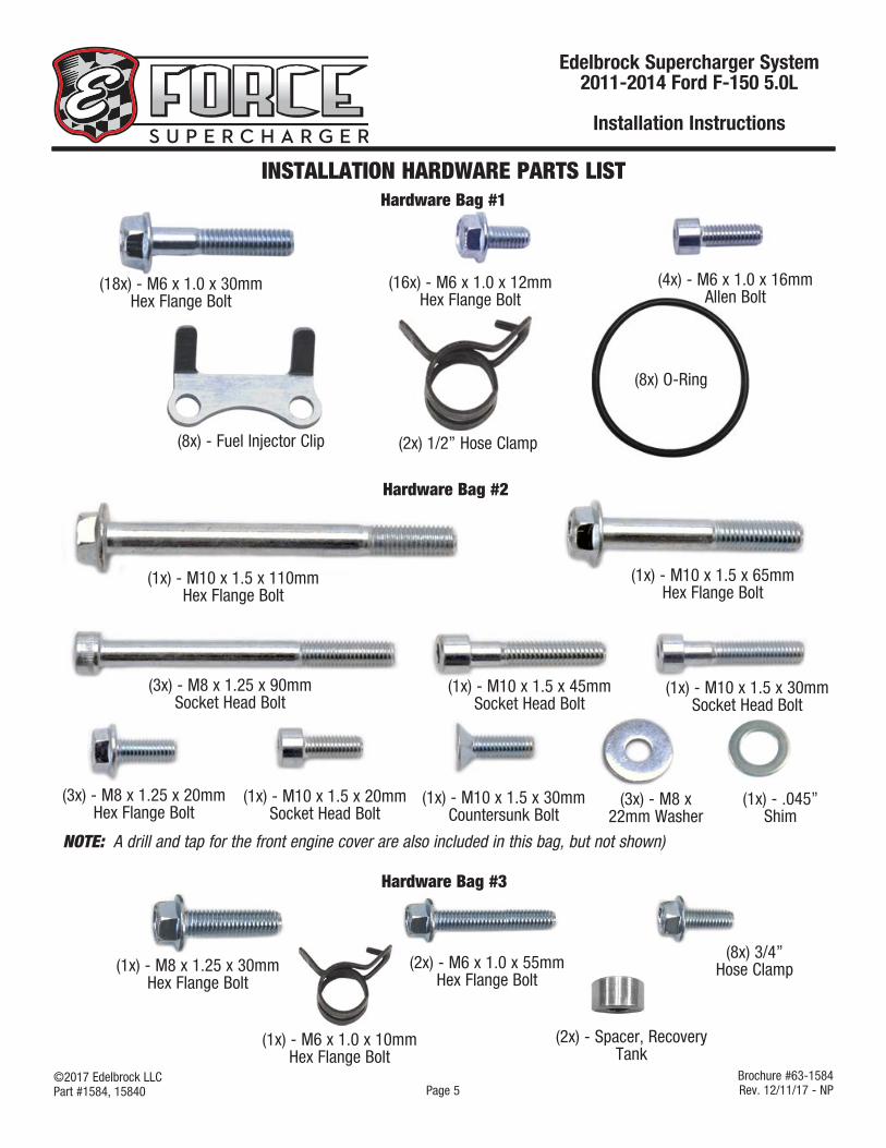
INSTALLATION HARDWARE PARTS LISTHardware Bag #1
Hardware Bag #2
(8x) - Fuel Injector Clip
(4x) - M6 x 1.0 x 16mm Allen Bolt
(1x) - M10 x 1.5 x 110mm Hex Flange Bolt
(1x) - M10 x 1.5 x 45mm Socket Head Bolt
(1x) - M10 x 1.5 x 65mm Hex Flange Bolt
(3x) - M8 x 1.25 x 90mm Socket Head Bolt
(1x) - M10 x 1.5 x 30mm Countersunk Bolt
(1x) - M10 x 1.5 x 20mm Socket Head Bolt
Hardware Bag #3
(1x) - M10 x 1.5 x 30mm Socket Head Bolt
(2x) 1/2” Hose Clamp
(3x) - M8 x 22mm Washer
(3x) - M8 x 1.25 x 20mm Hex Flange Bolt
(1x) - M8 x 1.25 x 30mm Hex Flange Bolt
NOTE: A drill and tap for the front engine cover are also included in this bag, but not shown)
(1x) - .045” Shim
(8x) O-Ring
(18x) - M6 x 1.0 x 30mm Hex Flange Bolt
(16x) - M6 x 1.0 x 12mm Hex Flange Bolt
(8x) 3/4” Hose Clamp
(1x) - M6 x 1.0 x 10mm Hex Flange Bolt
(2x) - M6 x 1.0 x 55mm Hex Flange Bolt
(2x) - Spacer, Recovery Tank

©2017 Edelbrock LLCPart #1584, 15840
Brochure #63-1584Rev. 12/11/17 - NP
Edelbrock Supercharger System 2011-2014 Ford F-150 5.0L
Installation Instructions
Page 6
Fuel Rail Crossover
Brake Aspirator to Intake Elbow
Heater Hose
Recovery Tank To Water Pump
Water Pump to LTR
LTR to Manifold
Driver Side PCV
HOSE IDENTIFICATION GUIDE
Manifold to Recovery Tank
Brake Aspirator to Manifold

©2017 Edelbrock LLCPart #1584, 15840
Brochure #63-1584Rev. 12/11/17 - NP
Edelbrock Supercharger System 2011-2014 Ford F-150 5.0L
Installation Instructions
Page 7
WIRE HARNESS GUIDE
Power Supply Wire
EVAP Solenoid
Engine Harness (EVAP Connector)
ACT Sensor
MAF Sensor
Engine Harness(MAF Connector)
Fuse
Relay
Ground Strap
Water Pump
ACT Harness
ETC Extension
Water Pump Harness

©2017 Edelbrock LLCPart #1584, 15840
Brochure #63-1584Rev. 12/11/17 - NP
Edelbrock Supercharger System 2011-2014 Ford F-150 5.0L
Installation Instructions
Page 8
Test Flash ProcedureUsing the procedure below, verify that your vehicle’s ECU & the suppled programmer are up to date, then use the programmer to flash the ECU thus verifying that they are
compatible.
Original Equipment Manufacturers often release updates to the computer programming for your vehicle. Edelbrock highly recommends that you verify, with your new car dealer, that your vehicle is equipped with the latest software version from your vehicle manufacturer, before attempting to load the Edelbrock tune.
Confirm that you have the latest calibration by checking the Edelbrock website (http://www.edelbrock.com/automotive_new/mc/ superchargers/software-tech.shtml ) Once you have found the latest tune on the site, power on the programmer, press the left arrow and select the Device Info option. Scroll down to Tune Version and compare that number to the one on the site. If they are different, download the new calibration as instructed on the website.
• Put the car into Acc mode, but don’t start the vehicle.
• Connect the supplied PCM cable to the OBD-II connector located below the steering wheel and to the left of your knee.
• Use directional pad to highlight Program Vehicle option and press Select button.
• Use directional pad to highlight Preprogrammed Tune option and press Select button.
• Read disclaimer then press Select to continue.
• Verify ignition is in the ‘Key On’ position but that the engine is not running then press Select.
• Use directional pad to highlight your vehicle and transmission combination then press Select.
• Use directional pad to highlight Begin Program then press Select.
• Depending on your specific drivetrain configuration, several separate operations may take place during this step. Completion of each operation will cause the progress bar to reset to zero.
DO NOT unplug the programmer until prompted.
• Turn the key off when prompted to do so by the handheld programmer.
• Read parting message from programmer then press Select to continue.
• Unplug the programmer cable from the OBD-II port.
• In the rare occurrence that you encounter an error message during the test flash procedure, please refer to pg. 25, titled, E-mail Edelbrock Your Stock PCM Calibration.
• Post Successful Test Flash
• If you are ready to install the supercharger, proceed to Step 1 of the Supercharger Installation
OR
• If you wish to return the ECU back to the factory calibration, such that the vehicle can still be driven until you are ready to begin the installation, then:
• Put the car into Acc mode, but don’t start the vehicle.
• Connect the supplied PCM cable to the OBD-II connector.
• Use directional pad to highlight Program Vehicle option and press Select button.
• Use directional pad to highlight Return To Stock option and press Select button.

©2017 Edelbrock LLCPart #1584, 15840
Brochure #63-1584Rev. 12/11/17 - NP
Edelbrock Supercharger System 2011-2014 Ford F-150 5.0L
Installation Instructions
Page 9
4. Detach the brake aspirator hose from intake elbow.
5. Loosen two (2) worm clamps on the intake elbow and throttle body tube. Detach the intake tube assembly from the air intake box and throttle body. Carefully lift the intake tube assembly up and remove the driver side PCV hose and brake booster hose.
Brake Booster
Driver PCV
6. Detach driver side PCV from the valve cover and set aside.
7. Disconnect the EVAP tube located at the top of the throttle body flange and disconnect EVAP connector. Use an 8mm socket to remove the two (2) bolts retaining the EVAP solenoid. Set the solenoid and bolts aside as they will be reused later.
• Follow the on screen instructions. Turn the key off when prompted to do so by the handheld programmer.
• Read parting message from programmer then press Select to continue.
• Unplug the programmer cable from the OBD-II port.
• When you are ready to Install the supercharger, proceed with Step 1 and you will be prompted to re-flash the ECU towards the end of the installation procedure.
Supercharger Installation
WARNING: Ensure that the engine has fully cooled before proceeding with this installation.
1. Disconnect NEGATIVE (-) battery terminal using an 8mm socket.
2. Drain the coolant by removing the petcock located on the lower passenger side of the radiator. Make sure to remove reservoir cap as well.
3. Disconnect the MAF connector from the MAF sensor on the air intake tube.

©2017 Edelbrock LLCPart #1584, 15840
Brochure #63-1584Rev. 12/11/17 - NP
Edelbrock Supercharger System 2011-2014 Ford F-150 5.0L
Installation Instructions
Page 10
8. Remove passenger side PCV hose from the passenger side valve cover and throttle body flange. Set PCV hose aside as it will be reused later.
9. Detach both lower brake aspirator hoses. Tuck brake aspirator assembly to the side to avoid damaging as it will be reused later.
10. Disconnect the throttle body plug from throttle body. Use an 8mm socket to remove the four (4) throttle body bolts. Remove throttle body and gasket. Set the throttle body, gasket and bolts aside for reuse later.
11. Remove two (2) foam fuel rail covers and discard. Using a 10mm socket, remove four (4) manifold/rail bolts located on top of the manifold.
12. Loosen/remove the fuel tank cap to release some of the fuel pressure from the fuel system. Place a shop rag around the fuel line fitting to absorb any gas that may leak. Depress the blue lock tab and pull the fuel line off the rail. CAUTION: Fuel may be under pressure and will spray a bit.
13. Detach all eight (8) fuel injector electrical connectors and carefully remove fuel rail assembly from the manifold.
14. Detach the two (2) heater hoses by pressing in the white tabs and pulling the hoses outwards. Remove the driver side heater hose from the firewall fitting.
15. Using pliers, remove the coolant overflow hose from the front of the manifold.
16. Use an 8mm socket to remove six (6) manifold bolts (there are a total of ten (10) manifold bolts, four (4) of which were removed in Step 11).

©2017 Edelbrock LLCPart #1584, 15840
Brochure #63-1584Rev. 12/11/17 - NP
Edelbrock Supercharger System 2011-2014 Ford F-150 5.0L
Installation Instructions
Page 11
17. Lift the manifold and carefully detach the wiring harness secured to the manifold with four (4) retaining clips on the rear of the manifold. Remove the manifold and set aside.
18. Carefully remove eight green O-ring seals from the manifold flanges. Clean and inspect the O-ring gaskets for any damage and replace if necessary. Set O-ring gaskets aside as they will be reused later.
19. Use a soft cloth to remove any contaminants on the sealing surfaces of the cylinder heads. Use masking tape to prevent any debris from entering the exposed ports.
20. Use an 8mm socket to remove the bolt retaining the passenger side coolant fitting. Pull the fitting out of the cylinder head and set it aside for reuse later. Cover the cavity with masking tape to prevent debris from entering.
21. Using a 15mm socket, release the tension from the primary drive tensioner by rotating the tensioner counter-clockwise. Remove the primary drive belt and discard. Then use a 13mm socket to remove the primary tensioner.
22. Using a 3/8” breaker bar or equivalent, release the tension form the secondary A/C drive tensioner and remove the A/C drive belt and discard.
23. Use a 10mm and 13mm socket (15mm on ‘14 Model Years) to remove the secondary A/C drive tensioner and the idler pulley.
CAUTION: The following A/C compressor belt installation procedures must be followed very closely to avoid damaging the stretchy a/c compressor belt. If you have any questions please contact Edelbrock’s Tech Hotline at 800-416-8628.
24. Position the A/C compressor belt behind the crankshaft pulley with the belt ribs facing towards the front of the vehicle. Carefully position the belt onto the A/C compressor pulley as shown.
NOTE: 2014 model years will use a 4 rib stretch belt. 2011-2013 model years will use a 6 rib stretch belt.
Belt Ribs

©2017 Edelbrock LLCPart #1584, 15840
Brochure #63-1584Rev. 12/11/17 - NP
Edelbrock Supercharger System 2011-2014 Ford F-150 5.0L
Installation Instructions
Page 12
25. Position the A/C compressor belt onto the top of the crankshaft pulley. Using the provided tie straps, securely hold the belt onto the crankshaft pulley at the 12 o’clock position. Do this by feeding the tie straps through the crankshaft pulley spokes, up and over the A/C compressor belt and then securely tighten the wire ties.
CAUTION: To avoid damaging the A/C compressor belt, make sure the belt is above the oil pan flange at all times during the installation process. The oil pan flange is very sharp and may cut into the belt if contact is made during the installation process.
Wire Ties
CAUTION: It is crucial to maintain the belt alignment with A/C compressor pulley when rotating the crankshaft pulley. This is done by carefully pulling the belt towards the front of the vehicle, with your free hand, while rotating the crankshaft pulley. The belt will have a tendency to skip a groove if not done so; resulting in an unusable belt.
26. With the A/C compressor belt positioned above the oil pan flange, slowly rotate the crankshaft pulley clockwise using a 19mm socket with a long ratchet or breaker bar. Continue rotating until the tie straps are at the 6 O’clock position.
27. Remove the tie strap and rotate the crankshaft clockwise 1 full rotation to verify the A/C compressor belt has correctly seated onto the crankshaft and A/C compressor pulley. Inspect the belt for any damages before proceeding.
NOTE: Carefully read Steps 28-30 below as it pertains to Figure 1 and the procedure to properly prep the new tensioner bracket mounting location on the passenger side engine cover.
28. Remove the indicated engine cover bolts using a 10mm socket. DO NOT drill or tap these bolt locations.
29. Use a 90˚ drill and the 8.5mm drill bit supplied in Bag #2, drill out holes #1 and #2 on the front engine cover (See Figure 1). Hole #1 should be drilled to .72” deep. Hole #2 should be drilled to 1.01” deep.
30. Tap hole #1 and #2 with the M10 x 1.5 tap from Bag #2. Remove all metal shavings from engine bay.
.72” Deep
1.01” Deep
Engine Cover Bolt
Figure 1
Engine Cover Bolt

©2017 Edelbrock LLCPart #1584, 15840
Brochure #63-1584Rev. 12/11/17 - NP
Edelbrock Supercharger System 2011-2014 Ford F-150 5.0L
Installation Instructions
Page 13
NOTE: Steps 31-35 refers to Figure 2 below.
31. Secure the new tensioner bracket to the bosses that were just drilled and tapped with bolts supplied in Bag #2.
NOTE: A .045” thick shim from Bag #2 is supplied to bridge the gap between the engine cover and the tensioner bracket. This location is secured using the M10 x 30mm countersunk bolt from Bag #2. Test fit the tensioner bracket to verify the shim is not require before proceeding.
32. Apply blue Loctite or equivalent, to threads and loosely install the following four (4) bolts, starting with the M10 x 30mm countersunk bolt into the countersunk feature of the bracket located on the left side of the bracket.
33. Loosely install the M8 x 90mm bolt through the engine cover hole at the top, then loosely install the M10 x 35mm bolt through the hole below and to the right.
34. Loosely install the M8 x 90mm bolt in the counter bore feature at the lower left section of the bracket.
35. Proceed by tightening the countersunk bolt first and then tightening the remaining surrounding bolts. Torque all bolts to 32 ft-lbs.
90mm
25mm (CS)40mm
90mm
36. Using a 15mm socket, remove the left bolt securing the alternator.
37. Using the bolts supplied in Bag #2, secure the small idler bracket by installing the M10 x 110mm bolt through the ear of the alternator, the M8 x 90mm bolt into the top front cover hole and the M10 x 45mm bolt through the center hole that was used to secure the stock tensioner. Torque M10 x 110mm bolt to 41 ft/lbs and the other two bolts to 18 ft-lb.
110mm45mm
90mm
38. Install the supplied tensioner with one (1) M10 x 65mm bolt from bag #2. Leave the tensioner bolt loose until the belt is installed. Install two (2) idler pulleys, one (1) 76mm and one (1) 65mm, with two (2) M8 x 20mm bolts and washers from bag #2. The smaller 65mm pulley should be installed on the uppermost boss on the tensioner bracket. Torque both idler pulley bolts to 18 ft-lbs.
65mm Pulley
76mm Pulley
Tensioner
39. Using one (1) M8 x 20mm bolt and one (1) M8 washer from bag #2, install the other 76mm pulley to the small idler pulley bracket. Torque to 18 ft-lbs. NOTE: 2014 Model Years will use a smaller 65mnm idler pulley.
©2017 Edelbrock LLCPart #1584, 15840
Brochure #63-1584Rev. 12/11/17 - NP
Edelbrock Supercharger System 2011-2014 Ford F-150 5.0L
Installation Instructions
Page 14
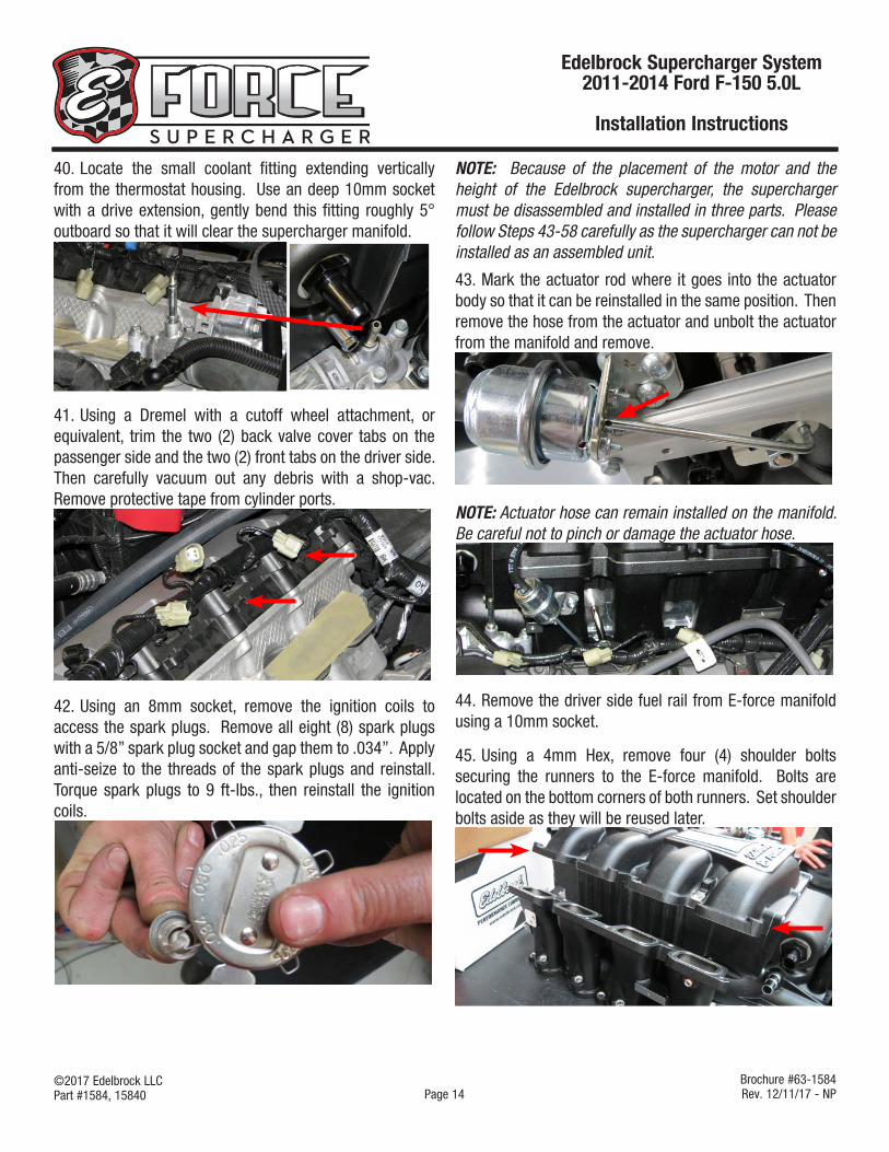
NOTE: Because of the placement of the motor and the height of the Edelbrock supercharger, the supercharger must be disassembled and installed in three parts. Please follow Steps 43-58 carefully as the supercharger can not be installed as an assembled unit.
43. Mark the actuator rod where it goes into the actuator body so that it can be reinstalled in the same position. Then remove the hose from the actuator and unbolt the actuator from the manifold and remove.
NOTE: Actuator hose can remain installed on the manifold. Be careful not to pinch or damage the actuator hose.
44. Remove the driver side fuel rail from E-force manifold using a 10mm socket.
45. Using a 4mm Hex, remove four (4) shoulder bolts securing the runners to the E-force manifold. Bolts are located on the bottom corners of both runners. Set shoulder bolts aside as they will be reused later.
40. Locate the small coolant fitting extending vertically from the thermostat housing. Use an deep 10mm socket with a drive extension, gently bend this fitting roughly 5° outboard so that it will clear the supercharger manifold.
41. Using a Dremel with a cutoff wheel attachment, or equivalent, trim the two (2) back valve cover tabs on the passenger side and the two (2) front tabs on the driver side. Then carefully vacuum out any debris with a shop-vac. Remove protective tape from cylinder ports.
42. Using an 8mm socket, remove the ignition coils to access the spark plugs. Remove all eight (8) spark plugs with a 5/8” spark plug socket and gap them to .034”. Apply anti-seize to the threads of the spark plugs and reinstall. Torque spark plugs to 9 ft-lbs., then reinstall the ignition coils.

©2017 Edelbrock LLCPart #1584, 15840
Brochure #63-1584Rev. 12/11/17 - NP
Edelbrock Supercharger System 2011-2014 Ford F-150 5.0L
Installation Instructions
Page 15
46. Using the factory green O-ring gaskets previously removed from the stock manifold, install four (4) o-ring gaskets onto the bottom of the driver side runner. Place the driver side runner onto the cylinder head ports (DO NOT bolt the runner down yet). Lay the runner down by tilting it towards the driver side as far right as possible.
47. Install the supplied ACT harness onto the ACT sensor located on the rear of the manifold.
48. Wrap the ACT harness around the manifold to avoid pinching or damaging the harness. With the help from an assistant, carefully lower the manifold onto the engine. The manifold must be tilted towards the passenger side to allow the actuator rod to clear the runner.
49. Using the remaining green O-ring gaskets removed from the stock manifold, install four (4) onto the bottom of the passenger side runner. Tilt the manifold towards the driver side and carefully slide in the passenger side runner over the cylinder ports.
50. Verify all eight (8) factory green O-ring gaskets are properly seated on the runners before proceeding.
51. Install four (4) supplied O-Rings onto the driver side runner as shown.
52. With the help of an assistant, lift the manifold up and carefully stand up the driver side runner. Align the runner with the manifold using the bolt holes as alignment guides.

©2017 Edelbrock LLCPart #1584, 15840
Brochure #63-1584Rev. 12/11/17 - NP
Edelbrock Supercharger System 2011-2014 Ford F-150 5.0L
Installation Instructions
Page 16
53. Verify that all O-rings are properly seated before proceeding. WARNING: This is very important as improperly seated O-rings will result in vacuum leaks.
54. Apply Blue Loctite to the threads of the two (2) M6 x 30mm bolts from bag #1. Using a 1/4” drive extension and 10mm socket, loosely install the bolts into the top provisions located in between the manifold runners. DO NOT force the bolts in and DO NOT use power tools as this may strip the threads on the runners.
M6 x 30mm Hex Head
55. Apply Blue Loctite to the threads on the two (2) M6 x 16mm Socket Head bolts from bag #1 and two (2) M6 x 17mm shoulder bolts removed from Step 45. Using a 5mm Hex tool, loosely install the 16mm bolts into the bottom center provisions on the runner flanges. Using a 4mm Hex tool, loosely install the 17mm shoulder bolts into the four (4) corners of the runner flange.
M6 x 16mm Socket Head
M6 x 17mm Shoulder Bolt
56. Verify that the driver side runner is flush with the manifold and that the o-rings are not pinched.
57. Repeat Step 51-56 to install the passenger side runner.
58. Tighten the inner manifold/runner bolts to 8 ft/lbs. Then tighten the outer manifold/runner bolts to 8 ft-lbs. DO NOT overtighten bolts as they may strip the threads.
59. Use a 10mm socket to install ten (10) M6 x 30mm bolts supplied in hardware bag #1. Then torque them to 8 ft-lbs in the sequence shown below.
60. Reinstall the actuator onto the actuator shaft by rotating the bypass lever counter-clockwise to align the notch on the rod with the keyhole. DO NOT bolt actuator onto the manifold.
61. Apply O-ring lube to the supplied fuel fitting O-rings and install them onto the supplied fittings (if not already done so). Kit includes three (3) -6 Black Plugs, two (2) short -6 Black 180° fitting and one (1) long -6 Black 180° fitting.
NOTE: Fuel rails are identical. Passenger and driver side will differ once the fittings have been installed.
62. Install two (2) -6 Black Plugs into both ends of the passenger side rail and one (1) short -6 Black 180° fitting to the bottom center of the fuel rail. The bottom center fitting must face inwards (towards the manifold) once the rail is installed.
Passenger Side

©2017 Edelbrock LLCPart #1584, 15840
Brochure #63-1584Rev. 12/11/17 - NP
Edelbrock Supercharger System 2011-2014 Ford F-150 5.0L
Installation Instructions
Page 17
63. Install one (1) -6 Black Plug into rear of the driver side rail, one (1) long 180° fitting onto the front of the fuel rail, and one (1) short 180° fitting onto the bottom center provision. The bottom center fitting must face inwards (towards the manifold) once the rail is installed.
Driver Side
64. Install injector alignment brackets onto the fuel rails using the M6 x 12mm bolts found in Bag #1. The tabs on the bracket must face outward and away from the manifold. NOTE: Alignment brackets on rails need to face outwards when rails are installed.
65. Apply O-ring lube to both ends of the supplied fuel injectors, then install them into the fuel rails, oriented so that the electrical connectors will face away from the manifold.
66. Position the actuator as shown and lower the driver side fuel rail assembly onto the supercharger. Line up the fuel injectors with their provisions on the manifold and gently push down on the rail until the fuel injectors are fully seated. Using a 10mm socket, install the two (2) M6 x 30mm bolts supplied in Bag #1 to secure the fuel rail to the manifold. Repeat Step 64-65 to install the passenger side fuel rail.
67. Line the actuator rod up with the mark previously made and reinstall the actuator with the bolts previously removed.
68. Install the supplied fuel cross over hose onto the two (2) center fittings on the driver and passenger fuel rails.

©2017 Edelbrock LLCPart #1584, 15840
Brochure #63-1584Rev. 12/11/17 - NP
Edelbrock Supercharger System 2011-2014 Ford F-150 5.0L
Installation Instructions
Page 18
69. Connect the fuel injector connectors from the main harness to the appropriate fuel injectors on the fuel rail.
70. Connect the factory fuel inlet line onto the 180° fitting on the front end of the driver side fuel rail.
71. Clock the tensioner so the rear pin fits in the slot on the tensioner bracket. Slide the supplied drive belt behind the tensioner and tighten the tensioner bolt; torque to 37 ft-lbs. With the belt positioned on the tensioner, use a 3/8” drive breaker bar to rotate the tensioner enough to install the belt onto one of the smooth idler pulleys. Use the diagram below for proper drive belt routing.
SUPERCHARGER
IDLER
IDLER
IDLER
CRANK
WATER PUMPTENSIONER
ALT.
72. Install the supplied heater hose to the firewall fitting and connect the heater hose to the driver side coolant fitting next to the throttle body flange.
73. Reinstall the passenger side coolant fitting and attach the factory heater hose to the fitting. Secure both heater hoses with the factory heater hose retaining clip.
74. Install the factory passenger side PCV hose to the passenger side valve cover barb and to the barb located on the supercharger nose.
75. Using a 10mm socket and four (4) M6 x 10mm bolts from bag #3, install the recovery tank bracket onto the recovery tank as shown below.

©2017 Edelbrock LLCPart #1584, 15840
Brochure #63-1584Rev. 12/11/17 - NP
Edelbrock Supercharger System 2011-2014 Ford F-150 5.0L
Installation Instructions
Page 19
76. Using a 10mm socket, remove the 2nd and 3rd front outer bolt from the passenger side valve cover. Remove the rubber grommet from the two bolts.
77. Insert the spacers from Bag #3 into the rubber grommets and install the recovery tank bracket onto the valve cover using the rubber grommets and two (2) M6 x 55mm bolts from Bag #3. Torque bolts to 8 ft-lbs. Red bracket shown for photo purposes only.
78. Install the manifold to recovery tank hose using two (2) 3/4” hose clamps from bag #3.
79. Using a Sharpie or equivalent, mark the current location of the hood latch. Remove two (2) hood latch bolts using a 10mm socket and loosely mount the upper LTR (Low Temp Radiator) bracket to the front of the hood latch as shown.
80. Using two (2) M6 x 10mm bolts from bag #3, attach the lower passenger side LTR bracket (small bracket with four (4) bolt holes) to the water pump bracket. Using a 21mm socket, remove the nut from the passenger side crash beam. Using a 10mm socket, remove the passenger side bumper reinforcement bolt. Position the water pump bracket assembly onto the crash beam stud and align with the bumper reinforcement provision. Secure the bracket assembly using the factory crash beam nut and the factory bumper reinforcement bolt. Now install the driver side LTR bracket by removing the driver side bumper reinforcement bolt and secure the driver side LTR bracket using the factory bumper reinforcement bolt.
Crash Beam Nut
Bumper Reinforcement BoltsM6 x 10mm
Water Pump Bracket
Driver Side LTR BracketPass Side
LTR Bracket
©2017 Edelbrock LLCPart #1584, 15840
Brochure #63-1584Rev. 12/11/17 - NP
Edelbrock Supercharger System 2011-2014 Ford F-150 5.0L
Installation Instructions
Page 20
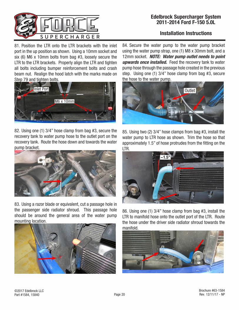
81. Position the LTR onto the LTR brackets with the inlet port in the up position as shown. Using a 10mm socket and six (6) M6 x 10mm bolts from bag #3, loosely secure the LTR to the LTR brackets. Properly align the LTR and tighten all bolts including bumper reinforcement bolts and crash beam nut. Realign the hood latch with the marks made on Step 79 and tighten bolts.
M6 x 10mm
Inlet Port
82. Using one (1) 3/4” hose clamp from bag #3, secure the recovery tank to water pump hose to the outlet port on the recovery tank. Route the hose down and towards the water pump bracket.
83. Using a razor blade or equivalent, cut a passage hole in the passenger side radiator shroud. This passage hole should be around the general area of the water pump mounting location.
84. Secure the water pump to the water pump bracket using the water pump strap, one (1) M8 x 30mm bolt, and a 12mm socket. NOTE: Water pump outlet needs to point upwards once installed. Feed the recovery tank to water pump hose through the passage hole created in the previous step. Using one (1) 3/4” hose clamp from bag #3, secure the hose to the water pump.
Outlet
85. Using two (2) 3/4” hose clamps from bag #3, install the water pump to LTR hose as shown. Trim the hose so that approximately 1.5” of hose protrudes from the fitting on the LTR.
~1.5”
86. Using one (1) 3/4” hose clamp from bag #3, install the LTR to manifold hose onto the outlet port of the LTR. Route the hose under the driver side radiator shroud towards the manifold.

©2017 Edelbrock LLCPart #1584, 15840
Brochure #63-1584Rev. 12/11/17 - NP
Edelbrock Supercharger System 2011-2014 Ford F-150 5.0L
Installation Instructions
Page 21
87. Reinstall the coolant overflow hose onto the thermostat housing fitting using the factory hose clamp.
88. Using one (1) 3/4” hose clamp from bag #3, secure the LTR to manifold hose to the inlet port on the supercharger manifold.
89. Install the factory EVAP solenoid onto the top of the nose inlet using the factory bolts, factory O-ring and an 8mm socket.
90. Install the factory EVAP hose onto the EVAP solenoid.
91. Install the stock throttle body onto the throttle body flange using the factory O-ring, factory bolts and an 8mm socket.
92. Replace the existing air filter with the new supplied air filter. Install the silicone elbow onto the throttle body and the intake box and secure using two (2) worm clamps.
93. Install the supplied driver side PCV hose to the driver side valve cover and the bottom PCV fitting on the intake elbow.
94. Reinstall the actuator hose back onto the actuator and secure the actuator hose to the factory retaining clip located on the EVAP hose.

©2017 Edelbrock LLCPart #1584, 15840
Brochure #63-1584Rev. 12/11/17 - NP
Edelbrock Supercharger System 2011-2014 Ford F-150 5.0L
Installation Instructions
Page 22
95. Using two (2) 1/2” hose clamps from bag #1, install the 5” hose with protected sleeve (blue) onto the .5” fitting on the manifold. Then install the hose onto the aspirator on the end next to the capped barb. Attach the supplied 90° aspirator hose (orange) to the intake elbow and then to the aspirator port below the factory hose (purple) barb.
Factory Brake Booster Hose
To ManifoldTo Elbow
96. Route the previously installed ACT harness from the back of the manifold, along side the driver side of the manifold, over towards the intake elbow.
97. Connect the female MAF adaptor on the ACT harness to the factory male MAF connector (green arrow). Connect the male MAF connector on the ACT harness to the factory MAF sensor. Secure the ACT harness to the existing vehicle harnesses with wire ties.
98. Remove the electrical tape wrapped around the factory throttle body connector and straighten the bent harness. Connect the supplied throttle body extension harness to the factory throttle body connector and to the throttle body sensor.
99. Using an 8mm (10mm on some vehicles) socket, mount the relay and fuse holder on the water pump harness to the stud located on the firewall harness cover. Now mount the GROUND (-) lead to the chassis ground on the firewall.
GROUND
100. Route POSITIVE (+) lead on the water pump harness over towards the positive terminal of the battery and install using a 8mm socket (10mm on some vehicles).

©2017 Edelbrock LLCPart #1584, 15840
Brochure #63-1584Rev. 12/11/17 - NP
Edelbrock Supercharger System 2011-2014 Ford F-150 5.0L
Installation Instructions
Page 23
101. Route water pump connector down towards the water pump and connect to the water pump. Secure the water pump harness to the factory A/C lines with wire ties.
102. Connect the factory female EVAP connector (green arrow) to the male EVAP connector on the water pump harness (red arrow). Then plug the female end of the water pump harness onto the EVAP solenoid. Secure the water pump harness to the existing nearby harnesses with wire ties.
103. Verify that the coolant petcock is closed, then refill the coolant system.
104. Fill the intercooler recovery tank with a 50/50 blend of water and coolant. Fill the tank until the water level is roughly 1” from the top of the threaded neck.
105. Reinstall the negative battery terminal. Turn the ignition key to the ‘ON’ position but DO NOT START the vehicle.
106. Visually inspect fuel rail, fuel lines, injectors and coolant lines for any leaks. If leaks are present, turn key off immediately and repair leaks. If leaks are not present, continue to the next step.
107. With the key in the “ON” position, verify that the coolant mixture is flowing briskly through the intercooler recovery tank. Top off coolant mixture as necessary and install the recovery tank cap once complete.
If you have yet to flash your ECU, then proceed with steps 108 - 120, otherwise disregard them.
108. It is recommended that you check the Edelbrock website at: (http://www.edelbrock.com/automotive_new/mc/superchargers/fuel_injected_soft-tech.shtml) to confirm that you have the latest calibration. Once you have found the latest tune on the site, power on the programmer, press the left arrow and select the Device Info option. Scroll down to “Tune Version” and compare that number to the one on the site. If they are different, download the new calibration with the supplied USB cable.
109. Put the car into ACC mode, but don’t start the vehicle
110. Connect the supplied PCM cable on the handheld programmer to the OBD-II connector located below the steering wheel, and to the left of your knee.
111. Use directional pad to highlight Program Vehicle option and press Select button.
112. Use directional pad to highlight Pre-programmed Tune option and press Select button.
113. Read disclaimer then press Select to continue.
114. Verify ignition is in the ‘Key On’ position but that the engine is not running then press Select.
115. Use directional pad to highlight your vehicle and transmission combination then press Select.

©2017 Edelbrock LLCPart #1584, 15840
Brochure #63-1584Rev. 12/11/17 - NP
Edelbrock Supercharger System 2011-2014 Ford F-150 5.0L
Installation Instructions
Page 24
116. Use directional pad to highlight Begin Program then press Select.
117. Depending on your specific drivetrain configuration, several separate operations may take place during this step. Completion of each operation will cause the progress bar to reset to zero.
DO NOT unplug the programmer until prompted.
118. Turn the vehicle off when prompted to do so by the handheld programmer.
119. Read parting message from programmer then press Select to continue.
120. Unplug the programmer cable from the OBD-II port.
121. If you have access to a diagnostic scan tool, run a ‘Key On, Engine Off’ test to verify that all connectors are properly installed, otherwise move on to the next step.
122. Start the vehicle and verify a smooth idle. If you are using a diagnostic scan tool, run a ‘Key On, Engine Run’ test.
123. Check all fluid levels before operating vehicle.
Congratulations on the installation of your new Edelbrock E-Force Supercharger System. If you have any questions, please call our Technical Support hotline and one of our technicians will be happy to assist you.

©2017 Edelbrock LLCPart #1584, 15840
Brochure #63-1584Rev. 12/11/17 - NP
Edelbrock Supercharger System 2011-2014 Ford F-150 5.0L
Installation Instructions
Page 25
E-mail Edelbrock Your Stock Vehicle Calibration
In the rare occurrence that you encounter an error message that reads “Calibration not supported” during the test flash procedure on page 8, you will need to e-mail Edlecbrock your stock vehicle calibration to [email protected]. Otherwise, disregard this step.
• Begin by downloading the SCT device updater software to your computer; it can be downloaded from: http://www.sctflash.com/software/SCTDeviceUpdater.exe
• Put the car into Acc mode but do not start it.
• Connect the supplied PCM cable from the tuner to the OBD-II connector.
• Select PROGRAM VEHICLE, arrow over to UPLOAD STOCK, press SELECT and follow the prompts on the screen.
• If the upload fails, you will be asked to AUTO DETECT, press SELECT and follow the prompts on the screen. If the auto detect fail, then please contact Edelbrock Tech support @ 800-416-8628
• Once the stock calibration has loaded, disconnect the programmer from the OBD-II connector and connect it to your PC using the supplied USB cable.
• Open the SCT software and select the button on the lower left hand side that reads GET STOCK FILE FROM DEVICE. Follow the instructions on the screen.
• Once the download is complete e-mail your stock calibration to [email protected], or call 1-800-416-8628 and our tech support staff will assist you in e-mailing the file.
NOTE: The subject line of your e-mail should be “file update needed”, The file will automatically be labeled using your VIN # followed by “.sul “ (XXXXXXXXXXXXX.sul)
• Once we have this file we can update the tune to work with your application, then we will e- mail you the custom tune which you may use until the release version is available. (This process can usually be completed within 1 to 2 business days)
• Download the new tune to the programmer using the directions received with the custom tune.
• Re-try the test flash procedure using the custom tune.