edelbrock e-force supercharger 2015-17 ford f-150 5 to the bypass assembly from manual movement will...
TRANSCRIPT
Edelbrock Supercharger System 2015-17 Ford F-150 5.0LInstallation Instructions
©2017 Edelbrock LLCPart #1557, 15570
Brochure #63-1557Rev. 12/5/17 - NP
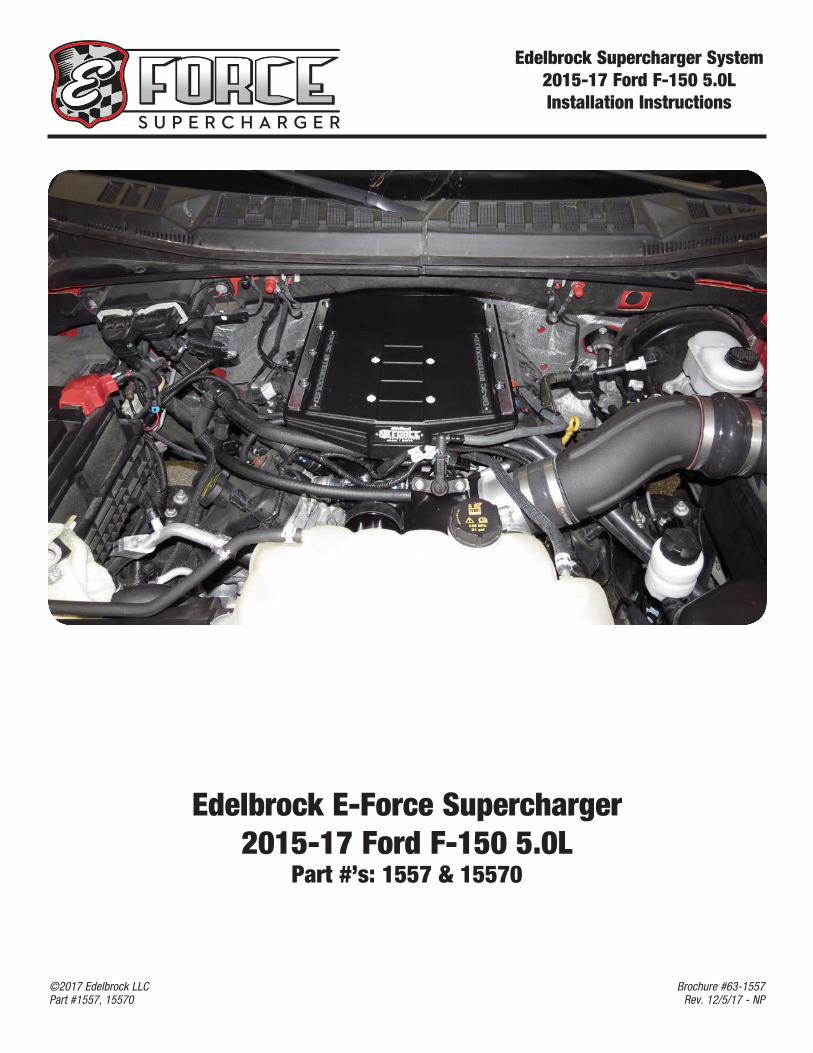
Edelbrock E-Force Supercharger2015-17 Ford F-150 5.0L
Part #’s: 1557 & 15570
Edelbrock Supercharger System 2015-17 Ford F-150 5.0LInstallation Instructions
©2017 Edelbrock LLCPart #1557, 15570
Brochure #63-1557Rev. 12/5/17 - NP
Edelbrock Supercharger System 2015-17 Ford F-150 5.0LInstallation Instructions
Page 1©2017 Edelbrock LLCPart #1557, 15570
Brochure #63-1557Rev. 12/5/17 - NP
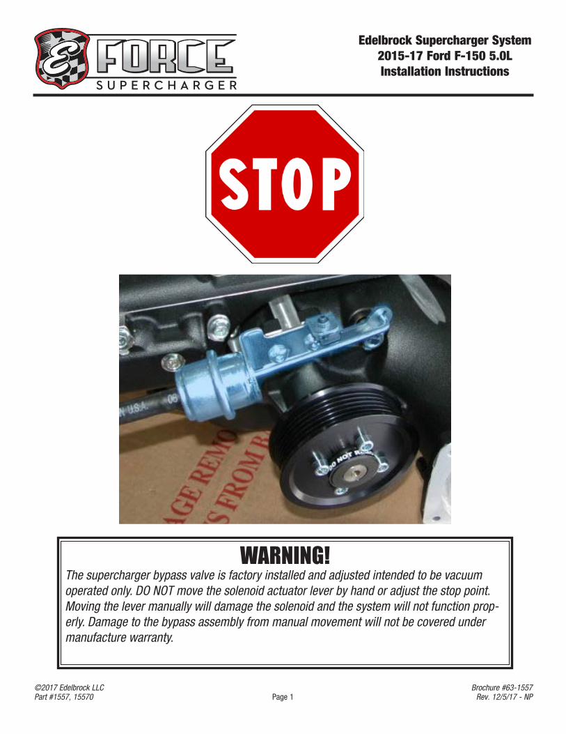
WARNING!The supercharger bypass valve is factory installed and adjusted intended to be vacuum operated only. DO NOT move the solenoid actuator lever by hand or adjust the stop point. Moving the lever manually will damage the solenoid and the system will not function prop-erly. Damage to the bypass assembly from manual movement will not be covered under manufacture warranty.
Edelbrock Supercharger System 2015-17 Ford F-150 5.0LInstallation Instructions
Page 2©2017 Edelbrock LLCPart #1557, 15570
Brochure #63-1557Rev. 12/5/17 - NP
Edelbrock Supercharger System 2015-17 Ford F-150 5.0LInstallation Instructions
Page 3©2017 Edelbrock LLCPart #1557, 15570
Brochure #63-1557Rev. 12/5/17 - NP
Edelbrock LLC, 2700 California Street, Torrance, CA 90503Toll-Free Tech Line: 1-800-416-8628
Thank you for purchasing the Edelbrock E-Force Supercharger System for the 2015-17 Ford F-150 5.0L. This Edelbrock E-Force Supercharger System utilizes Eaton’s Gen VI 2650 TVS Supercharger rotors, featuring a 4 lobe design with a 170° twist for maximum flow, minimum temperature rise, quiet operation, and superior reliability. The inverted design places the supercharger down low in the valley allowing for extra long runner lengths to maximize low end torque. A high-flow cold air intake system allows the supercharger to breathe easy resulting in cooler air intake temperatures and increased power potential. The industry leading air-to-water DP-3C intercooler paired with a massive front-mount low temperature radiator will ensure your engine is breathing cool air even in the most extreme conditions. With its ground pounding low end torque and high efficiency cooling system, the Edelbrock E-Force supercharger is the perfect match for your 5.0L F-150 truck.
Installation time: 9 Hours
INTRODUCTION
TOOLS & MATERIALS REQUIRED
l Jack and Jack Stands OR Service Liftl Panel Pullersl Ratchet and Socket Set including 7mm, 8mm (deep),
10mm, 10mm (deep), 12mm, 13mm, 15mm, 18mm (deep)
l 5mm & 6mm Allen Socketsl Allen Wrench Setl 3/8” Breaker Barl Screwdriversl Side cutters and or Dremel Tooll Spark Plug Gaping Tooll 90° Power Drill
l 1/4” Drill Bitl Pliers OR Hose Clamp Pliersl Blue Thread Lock Fluidl O-ring Lubel Masking Tape l Wire Ties (Zip Ties) l Shop Ragsl Torque Wrench l Utility knife l Heat Gunl 2 Gallons Motocraft Antifreeze/Coolant VC-3DIL-B Orange Pre-Diluted
Edelbrock Supercharger System 2015-17 Ford F-150 5.0LInstallation Instructions
Page 4©2017 Edelbrock LLCPart #1557, 15570
Brochure #63-1557Rev. 12/5/17 - NP
IMPORTANT WARNINGS
Edelbrock periodically releases improved versions of the calibration file found on the supplied handheld programmer. Check the website to ensure you have the latest version.
Before beginning the installation, use the enclosed checklist to verify that all components are present in the box. Then inspect each component for damages that may have occurred in transit. If any parts are missing or damaged, contact Edelbrock Technical Support, not your parts distributor.
WARNING: Installation of this supercharger will result in a significant change to the performance characteristics of your vehicle. It is highly recommended that you take some time to familiarize yourself with the added power and how it is delivered. It is highly recommend to do this in a controlled environment. Take extra care on wet and slippery roads, as the rear tires will be more likely to lose traction with the added power. It is never recommended to turn off your vehicles traction control system.
Due to the complexity of the Edelbrock E-Force Supercharging system, it is recommended that this system only be installed by a qualified professional with access to a service lift, pneumatic tools, and a strong familiarity with automotive service procedures. To qualify for the optional supplemental warranty, it is necessary to have this system installed by a Certified ASE Technician, Ford Dealership, or an Authorized Edelbrock Installer. Failure to do so will void and/or disqualify any and all optional supplemental warranties offered with this system. Please contact the Edelbrock Technical Support department if you have any questions regarding this system and/or how your installer of choice will affect any warranty coverage for which your vehicle may qualify.
Proper installation is the responsibility of the installer. Improper installation will void all manufacture’s standard warranties and may result in poor performance and engine or vehicle
damage.
Any equipment that directly modifies the fuel mixture or ignition timing of the engine can cause severe engine damage if used in conjunction with the Edelbrock E-Force Supercharger System. This includes, but is not limited to: ignition boxes, air/fuel controllers, OBDII programmers, and any other device that modifies signals to and/or from the ECU. Aftermarket bolt-on equipment such as underdrive pulleys or air intake kits will also conflict with the operation of the supercharger and must be removed prior to installation. Use of any of these products with the E-Force Supercharger could result in severe engine damage.
Any previously installed aftermarket tuning equipment must be removed and the vehicle returned to an as stock condition before installing the supercharger.
Edelbrock Supercharger System 2015-17 Ford F-150 5.0LInstallation Instructions
Page 5©2017 Edelbrock LLCPart #1557, 15570
Brochure #63-1557Rev. 12/5/17 - NP
The supercharger manifold includes a 1/8 NPT port to accommodate the installation of a boost gauge or pressure transducer. Remove the plug and replace it with a fitting to attach your gauge
or sensor.
The supercharger has been pre-drilled and tapped for a 1/8” NPT fitting at the rear of the passenger side intake runner flange. There is currently a plug sealing the hole, which can be removed, and replaced with a fitting to adapt to your sensor. CAUTION: Never cut into the vacuum lines leading to the bypass actuator for the purpose of tapping in a boost gauge. This can result in boost pressure readings that are higher than what is actually present in the intake plenum.
Do not use a wideband oxygen sensor in place of the rear O2 sensor when dyno testing this supercharger system. The voltage signal will cause the fuel system to run lean and possibly
cause engine damage.
91 octane or higher gasoline is required at all times. If your vehicle has been filled with anything less, it must be run until dry and refilled with 91
or higher octane gasoline twice prior to installation.
Failure to use the required 91 octane gasoline or higher could permanently damage your engine. Any failures associated with not using premium 91
octane gasoline or higher, will be ineligible for warranty repairs.
IMPORTANT WARNINGS (CONTINUE)
Edelbrock Authorized Installer Disclaimer
Authorized installers of Edelbrock products are independent companies over which Edelbrock has no right of control. Edelbrock LLC makes no claims regarding the abilities, expertise or competency of individual employees of any authorized installer. Each authorized installer is an independent company and makes its own independent judgments. Edelbrock LLC specifically disclaims any responsibility to any party including third parties for the actions, or the failure to act, of individuals, agents or a company authorized in the installation of Edelbrock LLC products.
Edelbrock Supercharger System 2015-17 Ford F-150 5.0LInstallation Instructions
Page 6©2017 Edelbrock LLCPart #1557, 15570
Brochure #63-1557Rev. 12/5/17 - NP
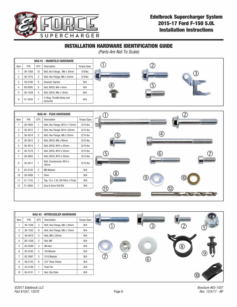
INSTALLATION HARDWARE IDENTIFICATION GUIDE (Parts Are Not To Scale)
BAG #1 - MANIFOLD HARDWARE
Item P/N QTY. Description Torque Spec
1 36-1508 10 Bolt, Hex Flange, M6 x 30mm 8 ft/lbs
2 36-1575 2 Bolt, Hex Flange, M6 x 25mm 8 ft/lbs
3 38-0186 8 Bracket, Injector N/A
4 68-0095 8 Bolt, BHCS, M4 x 4mm N/A
5 36-1528 4 Bolt, SHCS, M6 x 16mm N/A
6 51-4226 1O-Ring, Throttle Body (not pictured)
N/A
BAG #2 - FEAD HARDWARE
Item P/N QTY. Description Torque Spec
1 36-4056 1 Bolt, Hex Flange, M10 x 110mm 32 ft-lbs
2 36-4012 1 Bolt, Hex Flange, M10 x 65mm 32 ft-lbs
3 36-4018 3 Bolt, Hex Flange, M8 x 20mm 22 ft-lbs
4 36-3812 3 Bolt, SHCS, M8 x 90mm 22 ft-lbs
5 36-4013 1 Bolt, SHCS, M10 x 45mm 32 ft-lbs
6 36-1578 1 Bolt, SHCS, M10 x 35mm 32 ft-lbs
7 36-4063 1 Bolt, SHCS, M10 x 20mm 32 ft-lbs
8 36-4017 1Bolt, Countersunk, M10 x 30mm
32 ft-lbs
9 82-0120 3 M8 Washer N/A
10 36-4068 1 Shim N/A
11 51-7125 1 Tap, 10 x 1.50, D6 Pitch, 4 Flute N/A
12 51-6000 1 Size 8.5mm Drill Bit N/A
⑪ ⑫
BAG #3 - INTERCOOLER HARDWARE
Item P/N QTY. Description Torque Spec
1 36-1508 3 Bolt, Hex Flange, M6 x 30mm N/A
2 36-1552 6 Bolt, Hex Flange, M6 x 10mm N/A
3 36-4018 3 Bolt, M8 x 20mm N/A
4 60-1508 2 Nut, M6 N/A
5 60-9399 3 M8 Nut N/A
6 82-5240 2 3/8 Washer N/A
7 82-2897 3 5/16 Washer N/A
8 46-2155 8 3/4” Hose Clamp N/A
9 52-4199 1 Push Pin N/A
10 60-0101 1 Nut, Clip Style N/A
Edelbrock Supercharger System 2015-17 Ford F-150 5.0LInstallation Instructions
Page 7©2017 Edelbrock LLCPart #1557, 15570
Brochure #63-1557Rev. 12/5/17 - NP
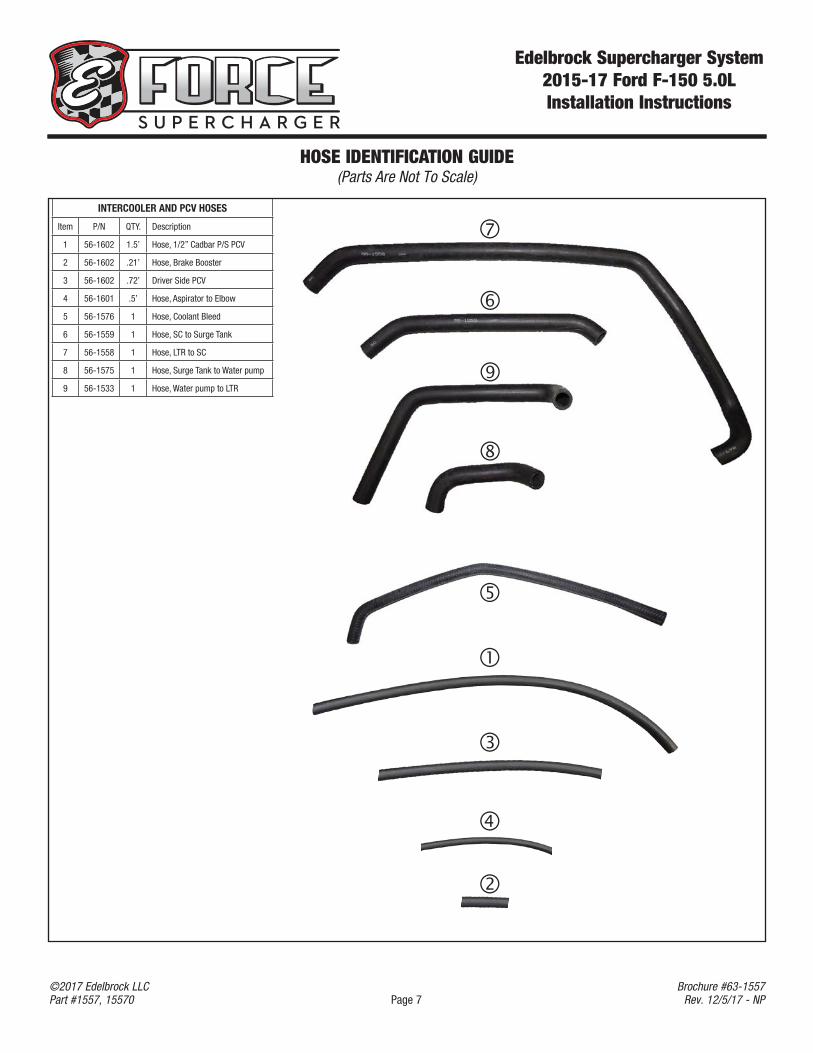
HOSE IDENTIFICATION GUIDE (Parts Are Not To Scale)
INTERCOOLER AND PCV HOSES
Item P/N QTY. Description
1 56-1602 1.5’ Hose, 1/2” Cadbar P/S PCV
2 56-1602 .21’ Hose, Brake Booster
3 56-1602 .72’ Driver Side PCV
4 56-1601 .5’ Hose, Aspirator to Elbow
5 56-1576 1 Hose, Coolant Bleed
6 56-1559 1 Hose, SC to Surge Tank
7 56-1558 1 Hose, LTR to SC
8 56-1575 1 Hose, Surge Tank to Water pump
9 56-1533 1 Hose, Water pump to LTR
Edelbrock Supercharger System 2015-17 Ford F-150 5.0LInstallation Instructions
Page 8©2017 Edelbrock LLCPart #1557, 15570
Brochure #63-1557Rev. 12/5/17 - NP
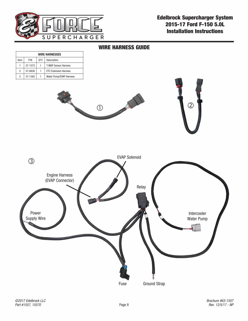
WIRE HARNESS GUIDE
Power Supply Wire
EVAP Solenoid
Engine Harness(EVAP Connector)
Fuse
Relay
Ground Strap
Intercooler Water Pump
WIRE HARNESSES
Item P/N QTY. Description
1 37-1573 1 T-MAP Sensor Harness
2 37-6626 1 ETC Extension Harness
3 37-1562 1 Water Pump/EVAP Harness
Edelbrock Supercharger System 2015-17 Ford F-150 5.0LInstallation Instructions
Page 9©2017 Edelbrock LLCPart #1557, 15570
Brochure #63-1557Rev. 12/5/17 - NP
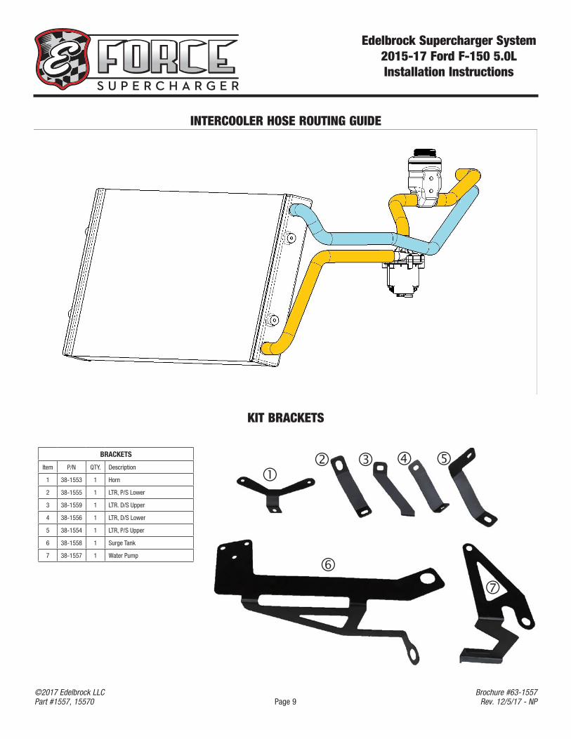
INTERCOOLER HOSE ROUTING GUIDE
KIT BRACKETS
BRACKETS
Item P/N QTY. Description
1 38-1553 1 Horn
2 38-1555 1 LTR, P/S Lower
3 38-1559 1 LTR. D/S Upper
4 38-1556 1 LTR, D/S Lower
5 38-1554 1 LTR, P/S Upper
6 38-1558 1 Surge Tank
7 38-1557 1 Water Pump
Edelbrock Supercharger System 2015-17 Ford F-150 5.0LInstallation Instructions
Page 10©2017 Edelbrock LLCPart #1557, 15570
Brochure #63-1557Rev. 12/5/17 - NP
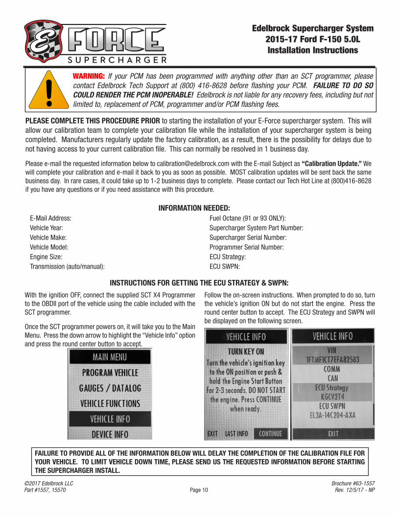
WARNING: If your PCM has been programmed with anything other than an SCT programmer, please contact Edelbrock Tech Support at (800) 416-8628 before flashing your PCM. FAILURE TO DO SO COULD RENDER THE PCM INOPERABLE! Edelbrock is not liable for any recovery fees, including but not limited to, replacement of PCM, programmer and/or PCM flashing fees.
PLEASE COMPLETE THIS PROCEDURE PRIOR to starting the installation of your E-Force supercharger system. This will allow our calibration team to complete your calibration file while the installation of your supercharger system is being completed. Manufacturers regularly update the factory calibration, as a result, there is the possibility for delays due to not having access to your current calibration file. This can normally be resolved in 1 business day.
Please e-mail the requested information below to [email protected] with the E-mail Subject as “Calibration Update.” We will complete your calibration and e-mail it back to you as soon as possible. MOST calibration updates will be sent back the same business day. In rare cases, it could take up to 1-2 business days to complete. Please contact our Tech Hot Line at (800)416-8628 if you have any questions or if you need assistance with this procedure.
E-Mail Address:Vehicle Year:Vehicle Make:Vehicle Model:Engine Size:Transmission (auto/manual):
Fuel Octane (91 or 93 ONLY):Supercharger System Part Number:Supercharger Serial Number:Programmer Serial Number:ECU Strategy:ECU SWPN:
INFORMATION NEEDED:
With the ignition OFF, connect the supplied SCT X4 Programmer to the OBDII port of the vehicle using the cable included with the SCT programmer.
Once the SCT programmer powers on, it will take you to the Main Menu. Press the down arrow to highlight the “Vehicle Info” option and press the round center button to accept.
Follow the on-screen instructions. When prompted to do so, turn the vehicle’s ignition ON but do not start the engine. Press the round center button to accept. The ECU Strategy and SWPN will be displayed on the following screen.
INSTRUCTIONS FOR GETTING THE ECU STRATEGY & SWPN:
FAILURE TO PROVIDE ALL OF THE INFORMATION BELOW WILL DELAY THE COMPLETION OF THE CALIBRATION FILE FOR YOUR VEHICLE. TO LIMIT VEHICLE DOWN TIME, PLEASE SEND US THE REQUESTED INFORMATION BEFORE STARTING THE SUPERCHARGER INSTALL.
Edelbrock Supercharger System 2015-17 Ford F-150 5.0LInstallation Instructions
Page 11©2017 Edelbrock LLCPart #1557, 15570
Brochure #63-1557Rev. 12/5/17 - NP
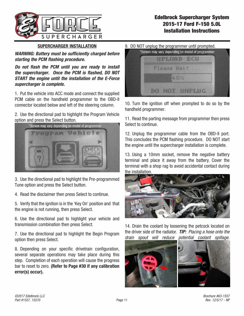
9. DO NOT unplug the programmer until prompted.
10. Turn the ignition off when prompted to do so by the handheld programmer.
11. Read the parting message from programmer then press Select to continue.
12. Unplug the programmer cable from the OBD-II port. This concludes the PCM flashing procedure. DO NOT start the engine until the supercharger installation is complete.
13. Using a 10mm socket, remove the negative battery terminal and place it away from the battery. Cover the terminal with a shop rag to avoid accidental contact during the installation.
14. Drain the coolant by loosening the petcock located on the driver side of the radiator. TIP: Placing a hose onto the drain spout will reduce potential coolant spillage.
SUPERCHARGER INSTALLATION
WARNING: Battery must be sufficiently charged before starting the PCM flashing procedure.
Do not flash the PCM until you are ready to install the supercharger. Once the PCM is flashed, DO NOT START the engine until the installation of the E-Force supercharger is complete.
1. Put the vehicle into ACC mode and connect the supplied PCM cable on the handheld programmer to the OBD-II connector located below and left of the steering column.
2. Use the directional pad to highlight the Program Vehicle option and press the Select button.
3. Use the directional pad to highlight the Pre-programmed Tune option and press the Select button.
4. Read the disclaimer then press Select to continue.
5. Verify that the ignition is in the ‘Key On’ position and that the engine is not running, then press Select.
6. Use the directional pad to highlight your vehicle and transmission combination then press Select.
7. Use the directional pad to highlight the Begin Program option then press Select.
8. Depending on your specific drivetrain configuration, several separate operations may take place during this step. Completion of each operation will cause the progress bar to reset to zero. (Refer to Page #30 if any calibration error(s) occur).
Edelbrock Supercharger System 2015-17 Ford F-150 5.0LInstallation Instructions
Page 12©2017 Edelbrock LLCPart #1557, 15570
Brochure #63-1557Rev. 12/5/17 - NP
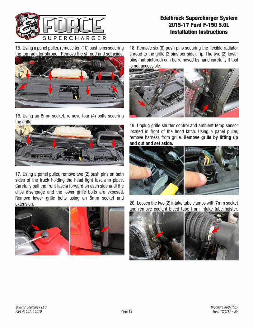
18. Remove six (6) push pins securing the flexible radiator shroud to the grille (3 pins per side). Tip: The two (2) lower pins (not pictured) can be removed by hand carefully if tool is not accessible.
19. Unplug grille shutter control and ambient temp sensor located in front of the hood latch. Using a panel puller, remove harness from grille. Remove grille by lifting up and out and set aside.
20. Loosen the two (2) intake tube clamps with 7mm socket and remove coolant bleed tube from intake tube holster.
15. Using a panel puller, remove ten (10) push pins securing the top radiator shroud. Remove the shroud and set aside.
16. Using an 8mm socket, remove four (4) bolts securing the grille.
17. Using a panel puller, remove two (2) push pins on both sides of the truck holding the head light fascia in place. Carefully pull the front fascia forward on each side until the clips disengage and the lower grille bolts are exposed. Remove lower grille bolts using an 8mm socket and extension.
Edelbrock Supercharger System 2015-17 Ford F-150 5.0LInstallation Instructions
Page 13©2017 Edelbrock LLCPart #1557, 15570
Brochure #63-1557Rev. 12/5/17 - NP
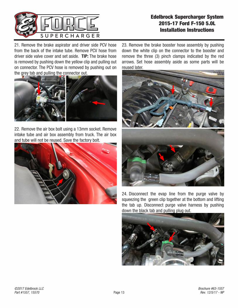
21. Remove the brake aspirator and driver side PCV hose from the back of the intake tube. Remove PCV hose from driver side valve cover and set aside. TIP: The brake hose is removed by pushing down the yellow clip and pulling out on connector. The PCV hose is removed by pushing out on the grey tab and pulling the connector out.
22. Remove the air box bolt using a 13mm socket. Remove intake tube and air box assembly from truck. The air box and tube will not be reused. Save the factory bolt.
23. Remove the brake booster hose assembly by pushing down the white clip on the connector to the booster and remove the three (3) pinch clamps indicated by the red arrows. Set hose assembly aside as some parts will be reused later.
24. Disconnect the evap line from the purge valve by squeezing the green clip together at the bottom and lifting the tab up. Disconnect purge valve harness by pushing down the black tab and pulling plug out.
Edelbrock Supercharger System 2015-17 Ford F-150 5.0LInstallation Instructions
Page 14©2017 Edelbrock LLCPart #1557, 15570
Brochure #63-1557Rev. 12/5/17 - NP
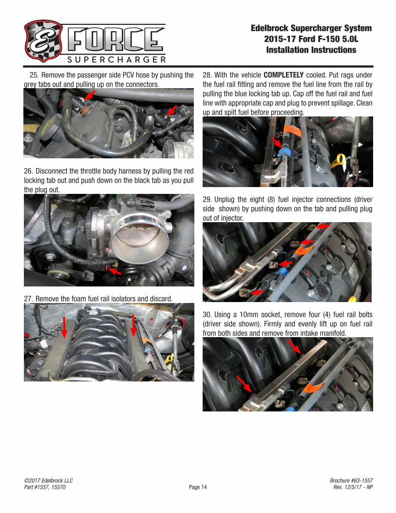
25. Remove the passenger side PCV hose by pushing the grey tabs out and pulling up on the connectors.
26. Disconnect the throttle body harness by pulling the red locking tab out and push down on the black tab as you pull the plug out.
27. Remove the foam fuel rail isolators and discard.
28. With the vehicle COMPLETELY cooled. Put rags under the fuel rail fitting and remove the fuel line from the rail by pulling the blue locking tab up. Cap off the fuel rail and fuel line with appropriate cap and plug to prevent spillage. Clean up and spilt fuel before proceeding.
29. Unplug the eight (8) fuel injector connections (driver side shown) by pushing down on the tab and pulling plug out of injector.
30. Using a 10mm socket, remove four (4) fuel rail bolts (driver side shown). Firmly and evenly lift up on fuel rail from both sides and remove from intake manifold.
Edelbrock Supercharger System 2015-17 Ford F-150 5.0LInstallation Instructions
Page 15©2017 Edelbrock LLCPart #1557, 15570
Brochure #63-1557Rev. 12/5/17 - NP
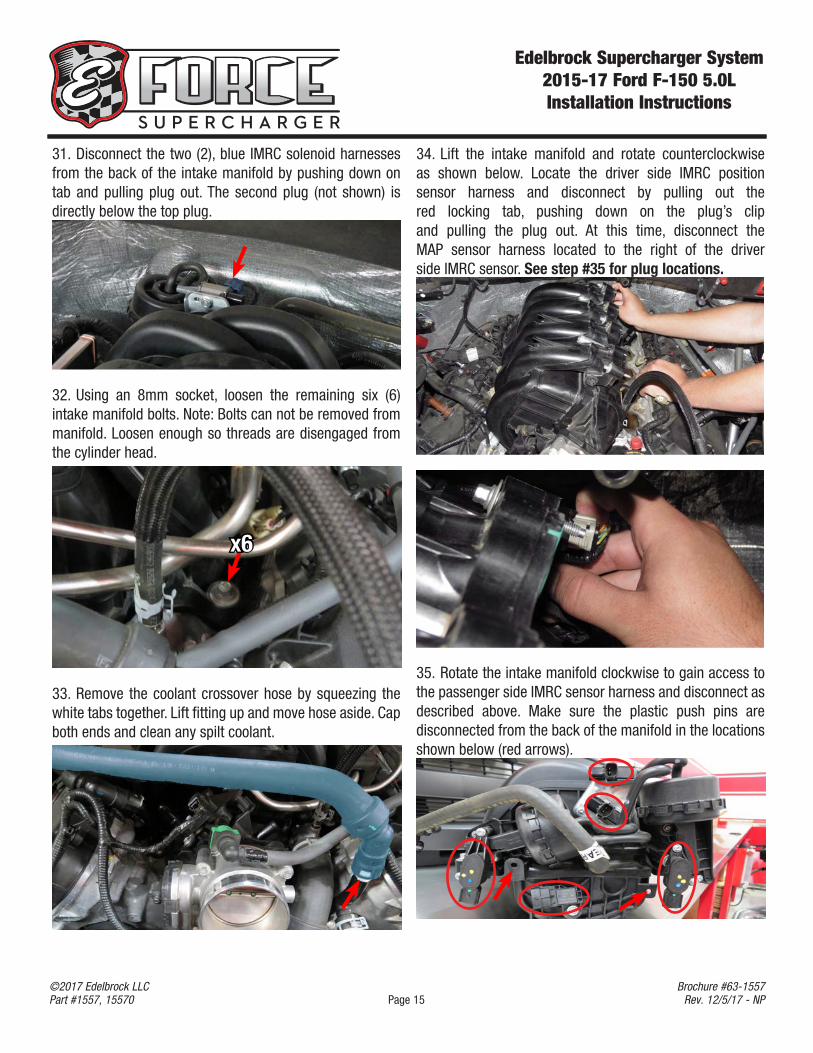
31. Disconnect the two (2), blue IMRC solenoid harnesses from the back of the intake manifold by pushing down on tab and pulling plug out. The second plug (not shown) is directly below the top plug.
32. Using an 8mm socket, loosen the remaining six (6) intake manifold bolts. Note: Bolts can not be removed from manifold. Loosen enough so threads are disengaged from the cylinder head.
x6
33. Remove the coolant crossover hose by squeezing the white tabs together. Lift fitting up and move hose aside. Cap both ends and clean any spilt coolant.
34. Lift the intake manifold and rotate counterclockwise as shown below. Locate the driver side IMRC position sensor harness and disconnect by pulling out the red locking tab, pushing down on the plug’s clip and pulling the plug out. At this time, disconnect the MAP sensor harness located to the right of the driver side IMRC sensor. See step #35 for plug locations.
35. Rotate the intake manifold clockwise to gain access to the passenger side IMRC sensor harness and disconnect as described above. Make sure the plastic push pins are disconnected from the back of the manifold in the locations shown below (red arrows).
Edelbrock Supercharger System 2015-17 Ford F-150 5.0LInstallation Instructions
Page 16©2017 Edelbrock LLCPart #1557, 15570
Brochure #63-1557Rev. 12/5/17 - NP
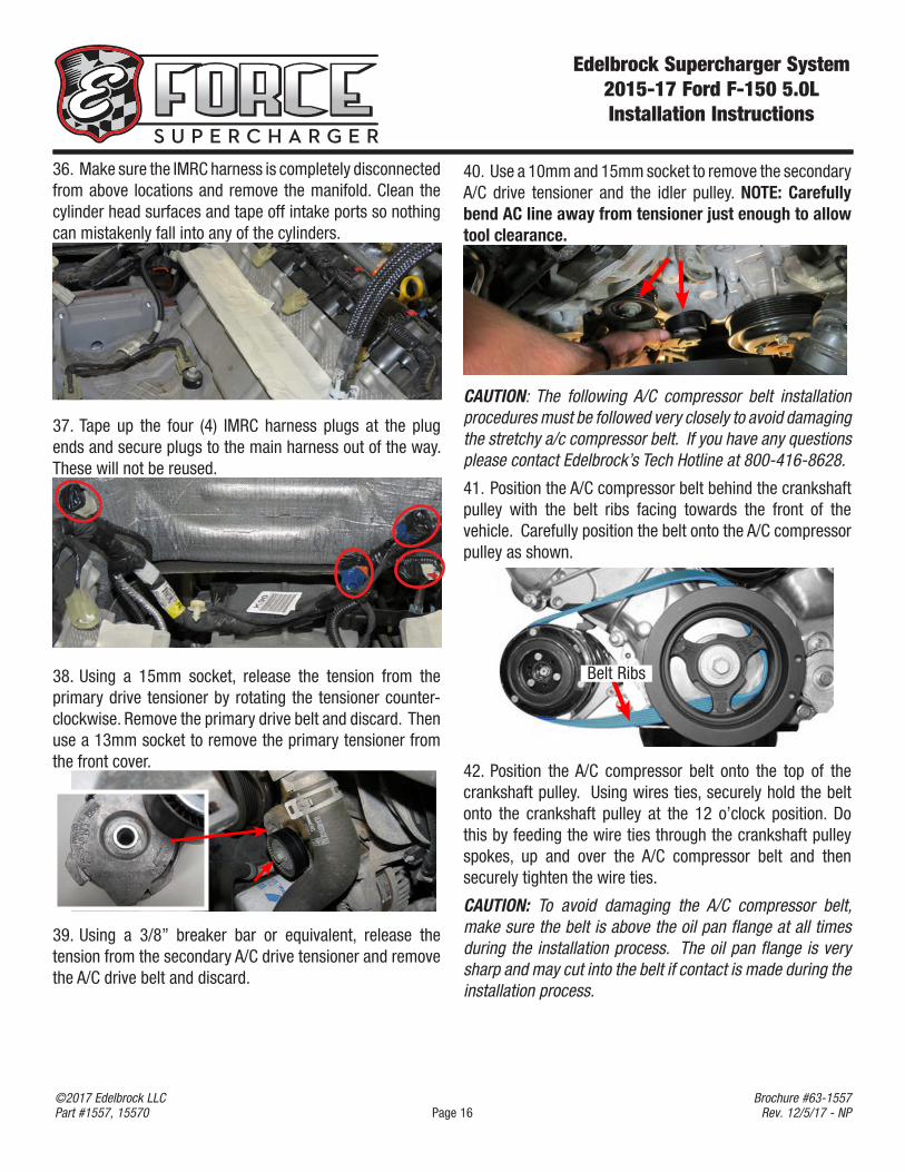
36. Make sure the IMRC harness is completely disconnected from above locations and remove the manifold. Clean the cylinder head surfaces and tape off intake ports so nothing can mistakenly fall into any of the cylinders.
37. Tape up the four (4) IMRC harness plugs at the plug ends and secure plugs to the main harness out of the way. These will not be reused.
38. Using a 15mm socket, release the tension from the primary drive tensioner by rotating the tensioner counter-clockwise. Remove the primary drive belt and discard. Then use a 13mm socket to remove the primary tensioner from the front cover.
39. Using a 3/8” breaker bar or equivalent, release the tension from the secondary A/C drive tensioner and remove the A/C drive belt and discard.
40. Use a 10mm and 15mm socket to remove the secondary A/C drive tensioner and the idler pulley. NOTE: Carefully bend AC line away from tensioner just enough to allow tool clearance.
CAUTION: The following A/C compressor belt installation procedures must be followed very closely to avoid damaging the stretchy a/c compressor belt. If you have any questions please contact Edelbrock’s Tech Hotline at 800-416-8628.
41. Position the A/C compressor belt behind the crankshaft pulley with the belt ribs facing towards the front of the vehicle. Carefully position the belt onto the A/C compressor pulley as shown.
Belt Ribs
42. Position the A/C compressor belt onto the top of the crankshaft pulley. Using wires ties, securely hold the belt onto the crankshaft pulley at the 12 o’clock position. Do this by feeding the wire ties through the crankshaft pulley spokes, up and over the A/C compressor belt and then securely tighten the wire ties.
CAUTION: To avoid damaging the A/C compressor belt, make sure the belt is above the oil pan flange at all times during the installation process. The oil pan flange is very sharp and may cut into the belt if contact is made during the installation process.
Edelbrock Supercharger System 2015-17 Ford F-150 5.0LInstallation Instructions
Page 17©2017 Edelbrock LLCPart #1557, 15570
Brochure #63-1557Rev. 12/5/17 - NP
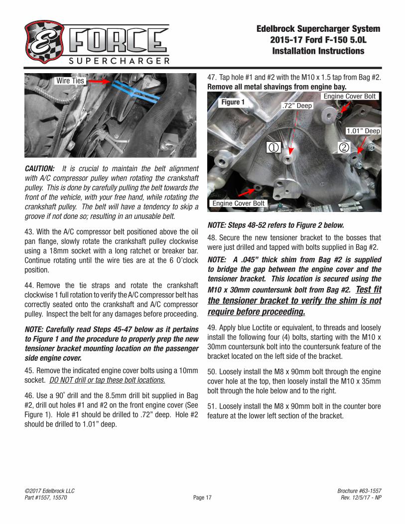
47. Tap hole #1 and #2 with the M10 x 1.5 tap from Bag #2. Remove all metal shavings from engine bay.
.72” Deep
1.01” Deep
Engine Cover Bolt
Figure 1
NOTE: Steps 48-52 refers to Figure 2 below.
48. Secure the new tensioner bracket to the bosses that were just drilled and tapped with bolts supplied in Bag #2.
NOTE: A .045” thick shim from Bag #2 is supplied to bridge the gap between the engine cover and the tensioner bracket. This location is secured using the M10 x 30mm countersunk bolt from Bag #2. Test fit the tensioner bracket to verify the shim is not require before proceeding.
49. Apply blue Loctite or equivalent, to threads and loosely install the following four (4) bolts, starting with the M10 x 30mm countersunk bolt into the countersunk feature of the bracket located on the left side of the bracket.
50. Loosely install the M8 x 90mm bolt through the engine cover hole at the top, then loosely install the M10 x 35mm bolt through the hole below and to the right.
51. Loosely install the M8 x 90mm bolt in the counter bore feature at the lower left section of the bracket.
Wire Ties
CAUTION: It is crucial to maintain the belt alignment with A/C compressor pulley when rotating the crankshaft pulley. This is done by carefully pulling the belt towards the front of the vehicle, with your free hand, while rotating the crankshaft pulley. The belt will have a tendency to skip a groove if not done so; resulting in an unusable belt.
43. With the A/C compressor belt positioned above the oil pan flange, slowly rotate the crankshaft pulley clockwise using a 18mm socket with a long ratchet or breaker bar. Continue rotating until the wire ties are at the 6 O’clock position.
44. Remove the tie straps and rotate the crankshaft clockwise 1 full rotation to verify the A/C compressor belt has correctly seated onto the crankshaft and A/C compressor pulley. Inspect the belt for any damages before proceeding.
NOTE: Carefully read Steps 45-47 below as it pertains to Figure 1 and the procedure to properly prep the new tensioner bracket mounting location on the passenger side engine cover.
45. Remove the indicated engine cover bolts using a 10mm socket. DO NOT drill or tap these bolt locations.
46. Use a 90˚ drill and the 8.5mm drill bit supplied in Bag #2, drill out holes #1 and #2 on the front engine cover (See Figure 1). Hole #1 should be drilled to .72” deep. Hole #2 should be drilled to 1.01” deep.
Engine Cover Bolt
Edelbrock Supercharger System 2015-17 Ford F-150 5.0LInstallation Instructions
Page 18©2017 Edelbrock LLCPart #1557, 15570
Brochure #63-1557Rev. 12/5/17 - NP
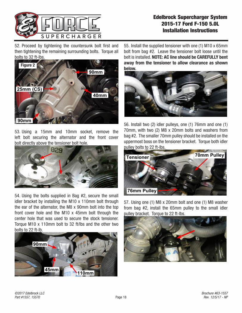
52. Proceed by tightening the countersunk bolt first and then tightening the remaining surrounding bolts. Torque all bolts to 32 ft-lbs.
90mm
25mm (CS)40mm
90mm
53. Using a 15mm and 10mm socket, remove the left bolt securing the alternator and the front cover bolt directly above the tensioner bolt hole.
54. Using the bolts supplied in Bag #2, secure the small idler bracket by installing the M10 x 110mm bolt through the ear of the alternator, the M8 x 90mm bolt into the top front cover hole and the M10 x 45mm bolt through the center hole that was used to secure the stock tensioner. Torque M10 x 110mm bolt to 32 ft/lbs and the other two bolts to 22 ft-lb.
110mm45mm
90mm
55. Install the supplied tensioner with one (1) M10 x 65mm bolt from bag #2. Leave the tensioner bolt loose until the belt is installed. NOTE: AC line should be CAREFULLY bent away from the tensioner to allow clearance as shown below.
56. Install two (2) idler pulleys, one (1) 76mm and one (1) 70mm, with two (2) M8 x 20mm bolts and washers from bag #2. The smaller 70mm pulley should be installed on the uppermost boss on the tensioner bracket. Torque both idler pulley bolts to 22 ft-lbs.
70mm Pulley
76mm Pulley
Tensioner
57. Using one (1) M8 x 20mm bolt and one (1) M8 washer from bag #2, install the 65mm pulley to the small idler pulley bracket. Torque to 22 ft-lbs.
Figure 2
Edelbrock Supercharger System 2015-17 Ford F-150 5.0LInstallation Instructions
Page 19©2017 Edelbrock LLCPart #1557, 15570
Brochure #63-1557Rev. 12/5/17 - NP
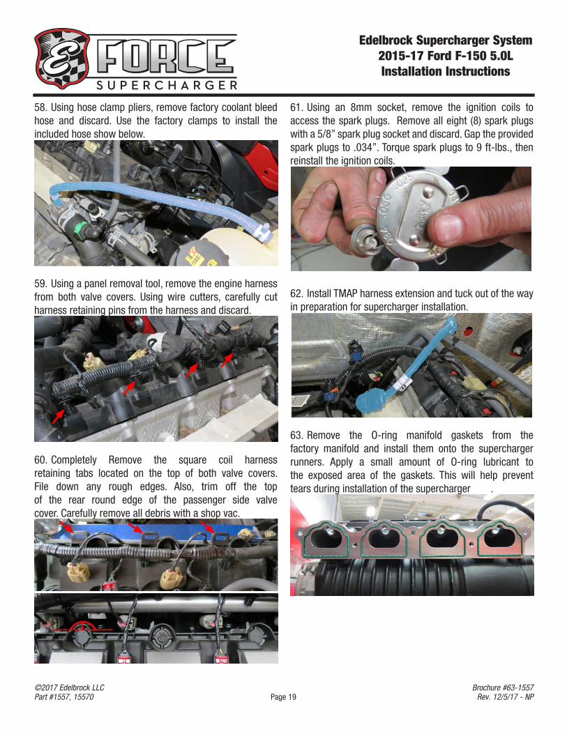
61. Using an 8mm socket, remove the ignition coils to access the spark plugs. Remove all eight (8) spark plugs with a 5/8” spark plug socket and discard. Gap the provided spark plugs to .034”. Torque spark plugs to 9 ft-lbs., then reinstall the ignition coils.
62. Install TMAP harness extension and tuck out of the way in preparation for supercharger installation.
63. Remove the O-ring manifold gaskets from the factory manifold and install them onto the supercharger runners. Apply a small amount of O-ring lubricant to the exposed area of the gaskets. This will help prevent tears during installation of the supercharger .
58. Using hose clamp pliers, remove factory coolant bleed hose and discard. Use the factory clamps to install the included hose show below.
59. Using a panel removal tool, remove the engine harness from both valve covers. Using wire cutters, carefully cut harness retaining pins from the harness and discard.
60. Completely Remove the square coil harness retaining tabs located on the top of both valve covers. File down any rough edges. Also, trim off the top of the rear round edge of the passenger side valve cover. Carefully remove all debris with a shop vac.
Edelbrock Supercharger System 2015-17 Ford F-150 5.0LInstallation Instructions
Page 20©2017 Edelbrock LLCPart #1557, 15570
Brochure #63-1557Rev. 12/5/17 - NP
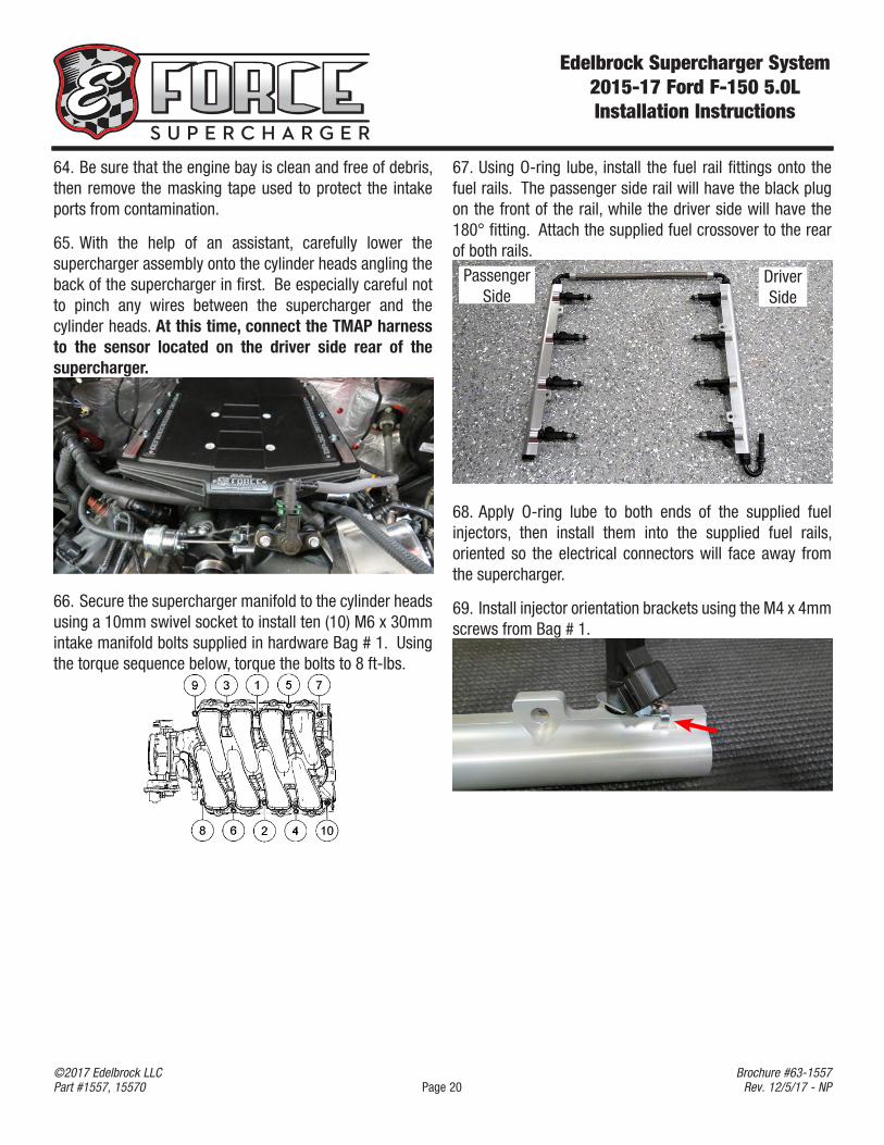
67. Using O-ring lube, install the fuel rail fittings onto the fuel rails. The passenger side rail will have the black plug on the front of the rail, while the driver side will have the 180° fitting. Attach the supplied fuel crossover to the rear of both rails.
Passenger Side
Driver Side
68. Apply O-ring lube to both ends of the supplied fuel injectors, then install them into the supplied fuel rails, oriented so the electrical connectors will face away from the supercharger.
69. Install injector orientation brackets using the M4 x 4mm screws from Bag # 1.
64. Be sure that the engine bay is clean and free of debris, then remove the masking tape used to protect the intake ports from contamination.
65. With the help of an assistant, carefully lower the supercharger assembly onto the cylinder heads angling the back of the supercharger in first. Be especially careful not to pinch any wires between the supercharger and the cylinder heads. At this time, connect the TMAP harness to the sensor located on the driver side rear of the supercharger.
66. Secure the supercharger manifold to the cylinder heads using a 10mm swivel socket to install ten (10) M6 x 30mm intake manifold bolts supplied in hardware Bag # 1. Using the torque sequence below, torque the bolts to 8 ft-lbs.
Edelbrock Supercharger System 2015-17 Ford F-150 5.0LInstallation Instructions
Page 21©2017 Edelbrock LLCPart #1557, 15570
Brochure #63-1557Rev. 12/5/17 - NP
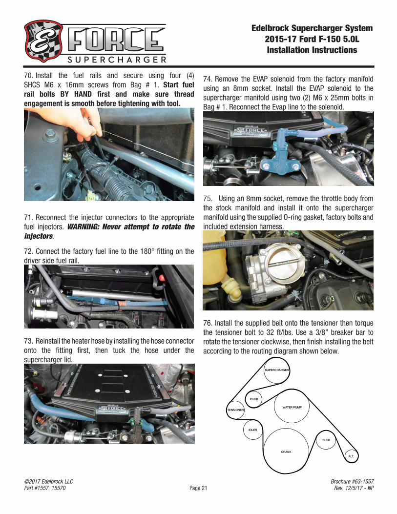
70. Install the fuel rails and secure using four (4) SHCS M6 x 16mm screws from Bag # 1. Start fuel rail bolts BY HAND first and make sure thread engagement is smooth before tightening with tool.
71. Reconnect the injector connectors to the appropriate fuel injectors. WARNING: Never attempt to rotate the injectors.
72. Connect the factory fuel line to the 180° fitting on the driver side fuel rail.
73. Reinstall the heater hose by installing the hose connector onto the fitting first, then tuck the hose under the supercharger lid.
74. Remove the EVAP solenoid from the factory manifold using an 8mm socket. Install the EVAP solenoid to the supercharger manifold using two (2) M6 x 25mm bolts in Bag # 1. Reconnect the Evap line to the solenoid.
75. Using an 8mm socket, remove the throttle body from the stock manifold and install it onto the supercharger manifold using the supplied O-ring gasket, factory bolts and included extension harness.
.
76. Install the supplied belt onto the tensioner then torque the tensioner bolt to 32 ft/lbs. Use a 3/8” breaker bar to rotate the tensioner clockwise, then finish installing the belt according to the routing diagram shown below.
SUPERCHARGER
IDLER
IDLER
IDLER
CRANK
WATER PUMPTENSIONER
ALT.
Edelbrock Supercharger System 2015-17 Ford F-150 5.0LInstallation Instructions
Page 22©2017 Edelbrock LLCPart #1557, 15570
Brochure #63-1557Rev. 12/5/17 - NP
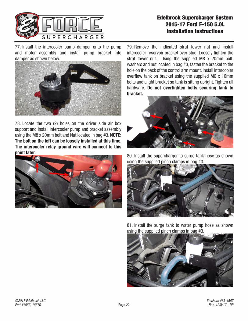
77. Install the intercooler pump damper onto the pump and motor assembly and install pump bracket into damper as shown below.
78. Locate the two (2) holes on the driver side air box support and install intercooler pump and bracket assembly using the M8 x 20mm bolt and Nut located in bag #3. NOTE: The bolt on the left can be loosely installed at this time. The intercooler relay ground wire will connect to this point later.
79. Remove the indicated strut tower nut and install intercooler reservoir bracket over stud. Loosely tighten the strut tower nut. Using the supplied M8 x 20mm bolt, washers and nut located in bag #3, fasten the bracket to the hole on the back of the control arm mount. Install intercooler overflow tank on bracket using the supplied M6 x 10mm bolts and alight bracket so tank is sitting upright. Tighten all hardware. Do not overtighten bolts securing tank to bracket.
80. Install the supercharger to surge tank hose as shown using the supplied pinch clamps in bag #3.
81. Install the surge tank to water pump hose as shown using the supplied pinch clamps in bag #3.
Edelbrock Supercharger System 2015-17 Ford F-150 5.0LInstallation Instructions
Page 23©2017 Edelbrock LLCPart #1557, 15570
Brochure #63-1557Rev. 12/5/17 - NP
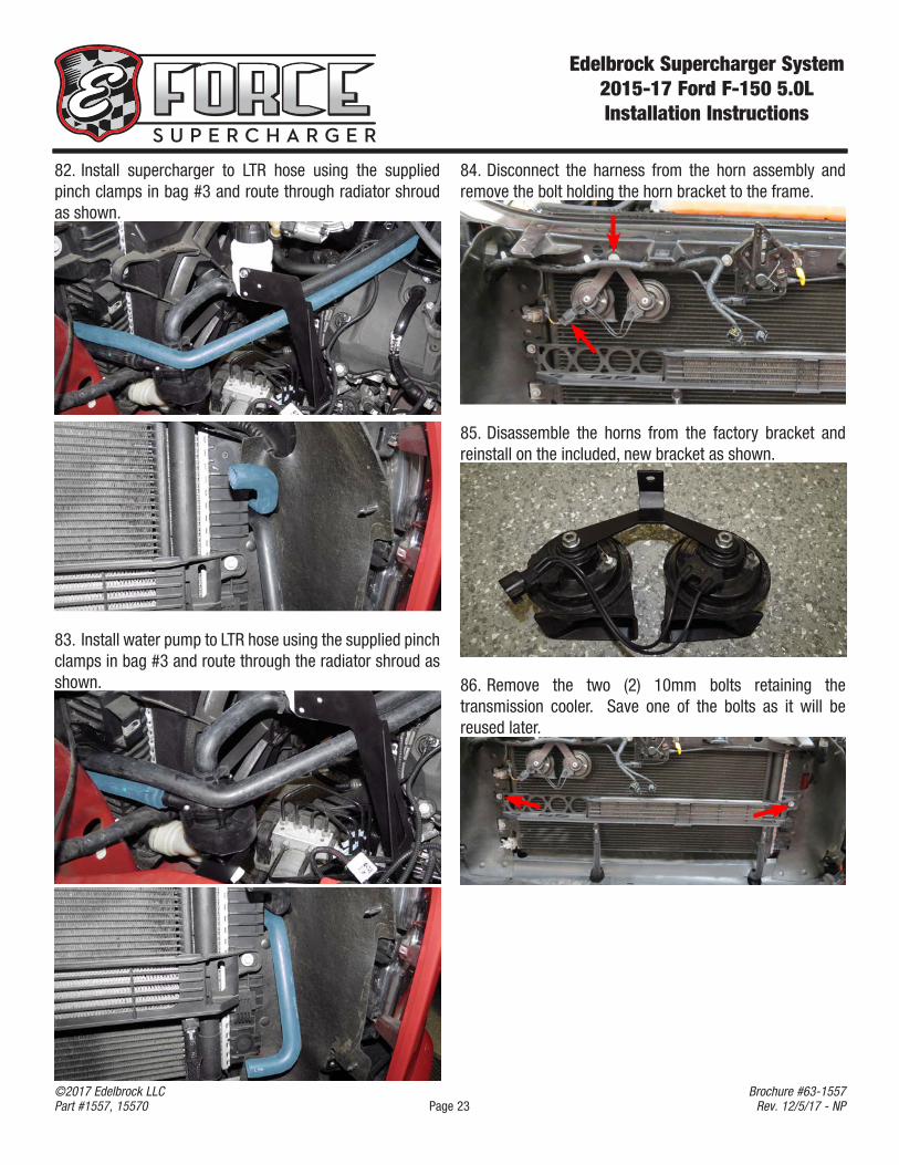
82. Install supercharger to LTR hose using the supplied pinch clamps in bag #3 and route through radiator shroud as shown.
83. Install water pump to LTR hose using the supplied pinch clamps in bag #3 and route through the radiator shroud as shown.
84. Disconnect the harness from the horn assembly and remove the bolt holding the horn bracket to the frame.
85. Disassemble the horns from the factory bracket and reinstall on the included, new bracket as shown.
86. Remove the two (2) 10mm bolts retaining the transmission cooler. Save one of the bolts as it will be reused later.
Edelbrock Supercharger System 2015-17 Ford F-150 5.0LInstallation Instructions
Page 24©2017 Edelbrock LLCPart #1557, 15570
Brochure #63-1557Rev. 12/5/17 - NP
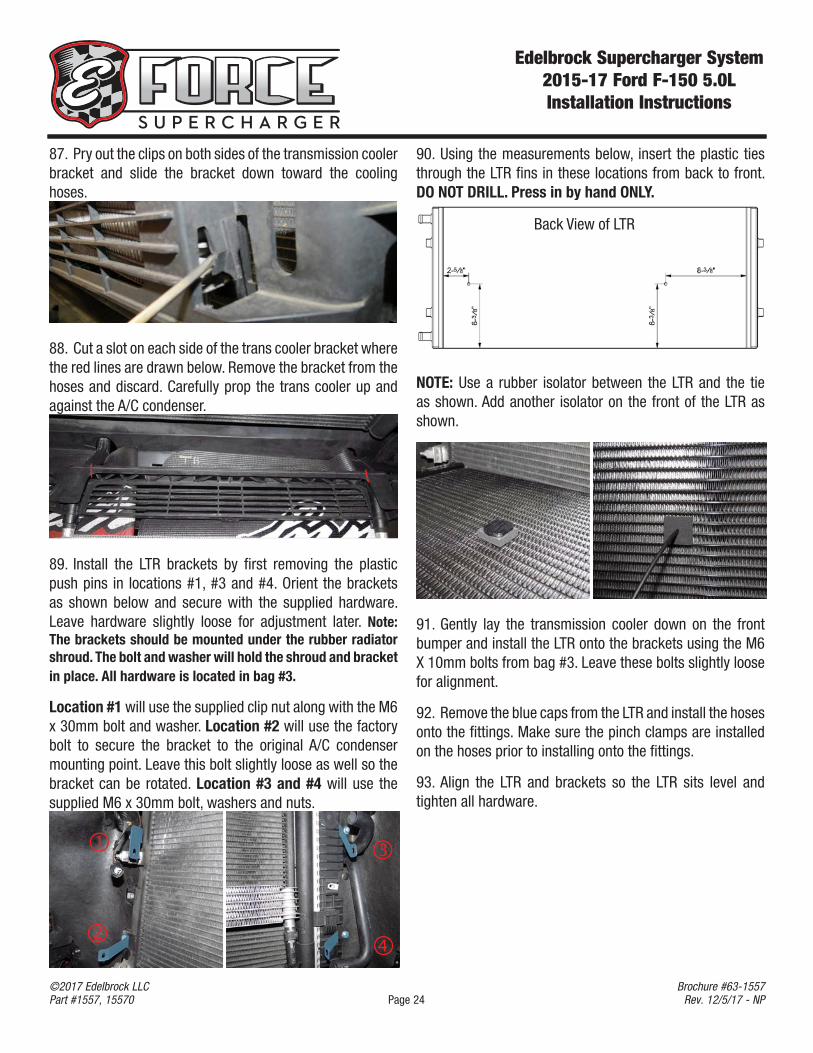
87. Pry out the clips on both sides of the transmission cooler bracket and slide the bracket down toward the cooling hoses.
88. Cut a slot on each side of the trans cooler bracket where the red lines are drawn below. Remove the bracket from the hoses and discard. Carefully prop the trans cooler up and against the A/C condenser.
89. Install the LTR brackets by first removing the plastic push pins in locations #1, #3 and #4. Orient the brackets as shown below and secure with the supplied hardware. Leave hardware slightly loose for adjustment later. Note: The brackets should be mounted under the rubber radiator shroud. The bolt and washer will hold the shroud and bracket in place. All hardware is located in bag #3.
Location #1 will use the supplied clip nut along with the M6 x 30mm bolt and washer. Location #2 will use the factory bolt to secure the bracket to the original A/C condenser mounting point. Leave this bolt slightly loose as well so the bracket can be rotated. Location #3 and #4 will use the supplied M6 x 30mm bolt, washers and nuts.
90. Using the measurements below, insert the plastic ties through the LTR fins in these locations from back to front. DO NOT DRILL. Press in by hand ONLY.
Back View of LTR
NOTE: Use a rubber isolator between the LTR and the tie as shown. Add another isolator on the front of the LTR as shown.
91. Gently lay the transmission cooler down on the front bumper and install the LTR onto the brackets using the M6 X 10mm bolts from bag #3. Leave these bolts slightly loose for alignment.
92. Remove the blue caps from the LTR and install the hoses onto the fittings. Make sure the pinch clamps are installed on the hoses prior to installing onto the fittings.
93. Align the LTR and brackets so the LTR sits level and tighten all hardware.
Edelbrock Supercharger System 2015-17 Ford F-150 5.0LInstallation Instructions
Page 25©2017 Edelbrock LLCPart #1557, 15570
Brochure #63-1557Rev. 12/5/17 - NP
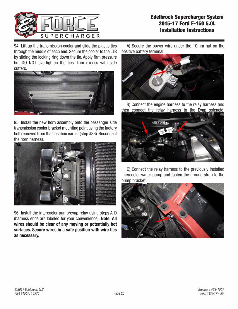
A) Secure the power wire under the 10mm nut on the positive battery terminal.
B) Connect the engine harness to the relay harness and then connect the relay harness to the Evap solenoid.
C) Connect the relay harness to the previously installed intercooler water pump and fasten the ground strap to the pump bracket.
94. Lift up the transmission cooler and slide the plastic ties through the middle of each end. Secure the cooler to the LTR by sliding the locking ring down the tie. Apply firm pressure but DO NOT overtighten the ties. Trim excess with side cutters.
95. Install the new horn assembly onto the passenger side transmission cooler bracket mounting point using the factory bolt removed from that location earlier (step #86). Reconnect the horn harness.
96. Install the intercooler pump/evap relay using steps A-D (harness ends are labeled for your convenience). Note: All wires should be clear of any moving or potentially hot surfaces. Secure wires in a safe position with wire ties as necessary.
Edelbrock Supercharger System 2015-17 Ford F-150 5.0LInstallation Instructions
Page 26©2017 Edelbrock LLCPart #1557, 15570
Brochure #63-1557Rev. 12/5/17 - NP
D) Position the relay on the driver side plastic wheel well as shown below. Make sure the wires have some slack and mark the area inside the metal tab attached to the relay. Drill a 1/4” hole on the mark and fasten the relay to the new mounting point using the supplied push pin in bag #3.
97. Using the factory 45° valve cover fitting, install the passenger side 1/2” PCV line as sown. Tip: A heat gun or razor blade may be used to free the factory fitting from the original hard line.
Follow Steps 98-102 to assemble and install the new air intake system.
98. Mount the filter adapter inside of the air box as shown using the three (3) 1/4-20 screws and washers.
Insert the 5/8” grommet and spacer into the opposite side of the air box.
Snap the new air scoop into the air box and secure with 8-32 button head screw, lock washer and flat washer as shown below.
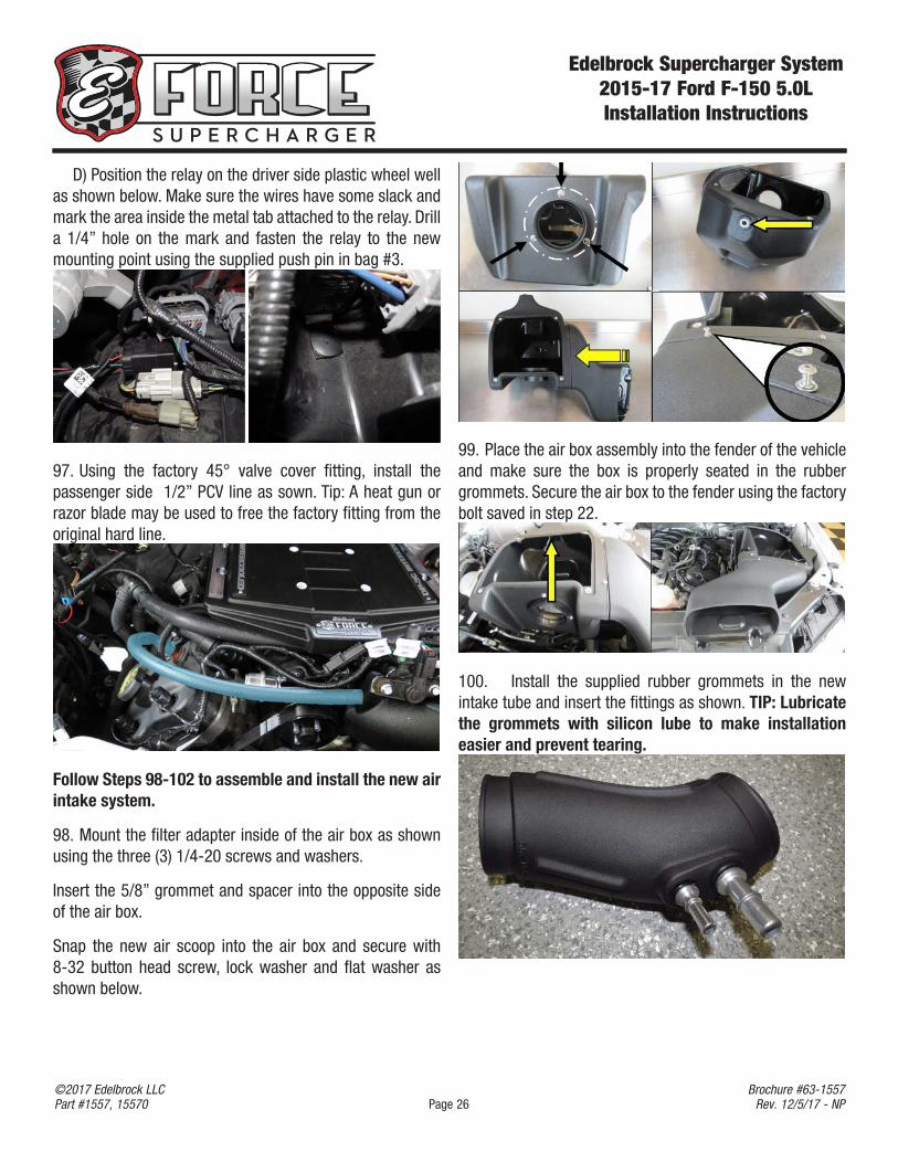
99. Place the air box assembly into the fender of the vehicle and make sure the box is properly seated in the rubber grommets. Secure the air box to the fender using the factory bolt saved in step 22.
100. Install the supplied rubber grommets in the new intake tube and insert the fittings as shown. TIP: Lubricate the grommets with silicon lube to make installation easier and prevent tearing.
Edelbrock Supercharger System 2015-17 Ford F-150 5.0LInstallation Instructions
Page 27©2017 Edelbrock LLCPart #1557, 15570
Brochure #63-1557Rev. 12/5/17 - NP
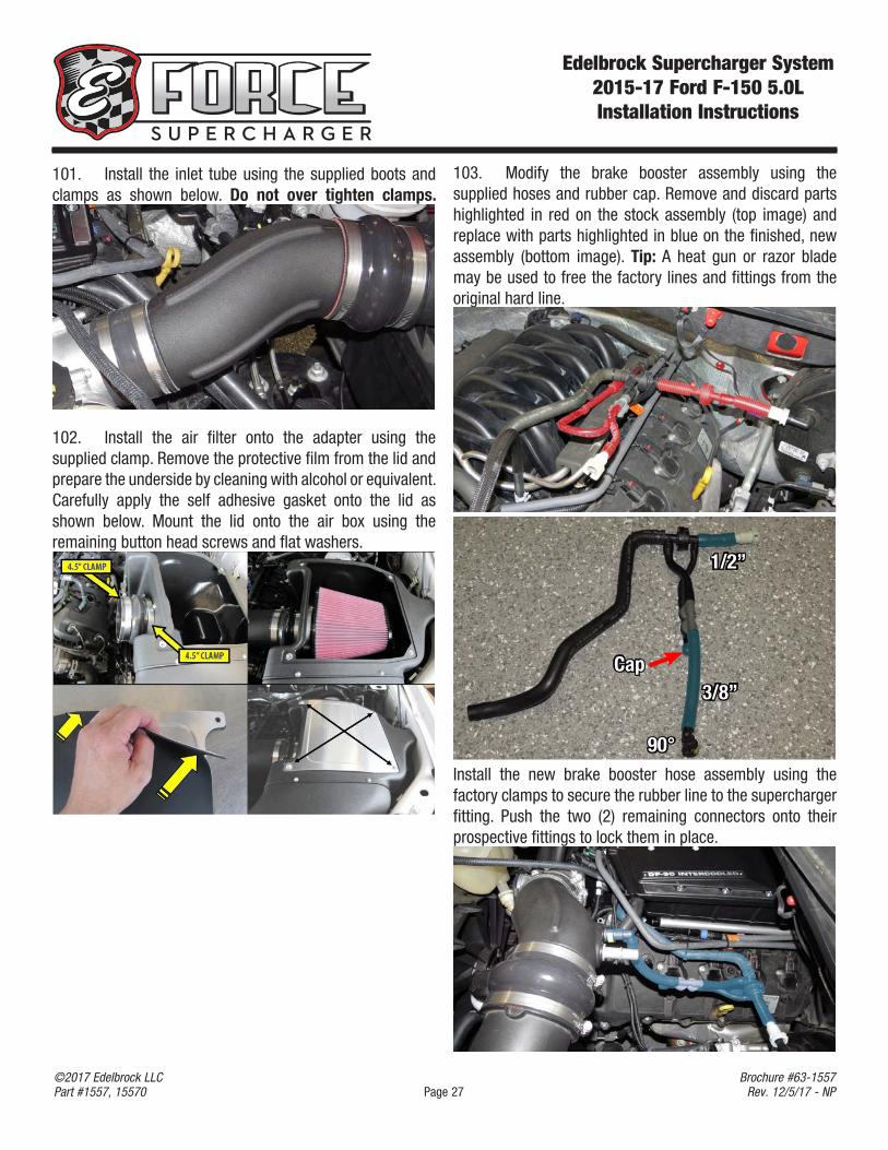
101. Install the inlet tube using the supplied boots and clamps as shown below. Do not over tighten clamps.
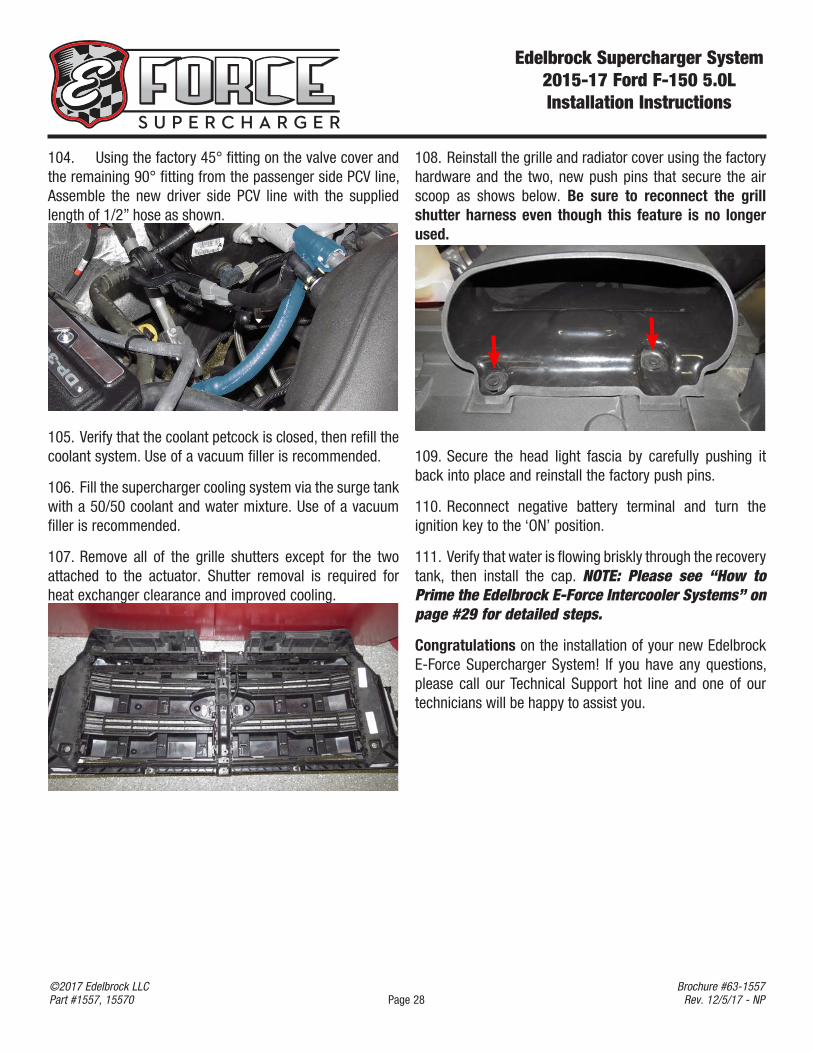
102. Install the air filter onto the adapter using the supplied clamp. Remove the protective film from the lid and prepare the underside by cleaning with alcohol or equivalent. Carefully apply the self adhesive gasket onto the lid as shown below. Mount the lid onto the air box using the remaining button head screws and flat washers.
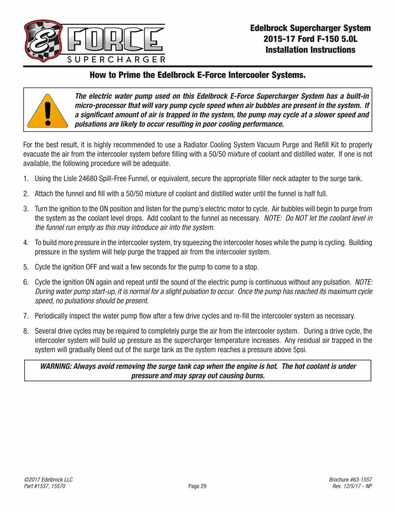
103. Modify the brake booster assembly using the supplied hoses and rubber cap. Remove and discard parts highlighted in red on the stock assembly (top image) and replace with parts highlighted in blue on the finished, new assembly (bottom image). Tip: A heat gun or razor blade may be used to free the factory lines and fittings from the original hard line.
Cap3/8”
1/2”
90°Install the new brake booster hose assembly using the factory clamps to secure the rubber line to the supercharger fitting. Push the two (2) remaining connectors onto their prospective fittings to lock them in place.
Edelbrock Supercharger System 2015-17 Ford F-150 5.0LInstallation Instructions
Page 28©2017 Edelbrock LLCPart #1557, 15570
Brochure #63-1557Rev. 12/5/17 - NP
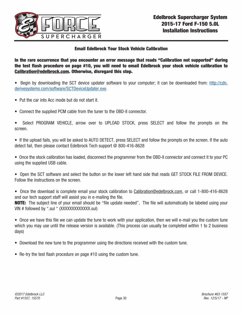
104. Using the factory 45° fitting on the valve cover and the remaining 90° fitting from the passenger side PCV line, Assemble the new driver side PCV line with the supplied length of 1/2” hose as shown.
105. Verify that the coolant petcock is closed, then refill the coolant system. Use of a vacuum filler is recommended.
106. Fill the supercharger cooling system via the surge tank with a 50/50 coolant and water mixture. Use of a vacuum filler is recommended.
107. Remove all of the grille shutters except for the two attached to the actuator. Shutter removal is required for heat exchanger clearance and improved cooling.
108. Reinstall the grille and radiator cover using the factory hardware and the two, new push pins that secure the air scoop as shows below. Be sure to reconnect the grill shutter harness even though this feature is no longer used.
109. Secure the head light fascia by carefully pushing it back into place and reinstall the factory push pins.
110. Reconnect negative battery terminal and turn the ignition key to the ‘ON’ position.
111. Verify that water is flowing briskly through the recovery tank, then install the cap. NOTE: Please see “How to Prime the Edelbrock E-Force Intercooler Systems” on page #29 for detailed steps.
Congratulations on the installation of your new Edelbrock E-Force Supercharger System! If you have any questions, please call our Technical Support hot line and one of our technicians will be happy to assist you.
Edelbrock Supercharger System 2015-17 Ford F-150 5.0LInstallation Instructions
Page 29©2017 Edelbrock LLCPart #1557, 15570
Brochure #63-1557Rev. 12/5/17 - NP
How to Prime the Edelbrock E-Force Intercooler Systems.
The electric water pump used on this Edelbrock E-Force Supercharger System has a built-in micro-processor that will vary pump cycle speed when air bubbles are present in the system. If a significant amount of air is trapped in the system, the pump may cycle at a slower speed and pulsations are likely to occur resulting in poor cooling performance.
For the best result, it is highly recommended to use a Radiator Cooling System Vacuum Purge and Refill Kit to properly evacuate the air from the intercooler system before filling with a 50/50 mixture of coolant and distilled water. If one is not available, the following procedure will be adequate.
1. Using the Lisle 24680 Spill-Free Funnel, or equivalent, secure the appropriate filler neck adapter to the surge tank.
2. Attach the funnel and fill with a 50/50 mixture of coolant and distilled water until the funnel is half full.
3. Turn the ignition to the ON position and listen for the pump’s electric motor to cycle. Air bubbles will begin to purge from the system as the coolant level drops. Add coolant to the funnel as necessary. NOTE: Do NOT let the coolant level in the funnel run empty as this may introduce air into the system.
4. To build more pressure in the intercooler system, try squeezing the intercooler hoses while the pump is cycling. Building pressure in the system will help purge the trapped air from the intercooler system.
5. Cycle the ignition OFF and wait a few seconds for the pump to come to a stop.
6. Cycle the ignition ON again and repeat until the sound of the electric pump is continuous without any pulsation. NOTE: During water pump start-up, it is normal for a slight pulsation to occur. Once the pump has reached its maximum cycle speed, no pulsations should be present.
7. Periodically inspect the water pump flow after a few drive cycles and re-fill the intercooler system as necessary.
8. Several drive cycles may be required to completely purge the air from the intercooler system. During a drive cycle, the intercooler system will build up pressure as the supercharger temperature increases. Any residual air trapped in the system will gradually bleed out of the surge tank as the system reaches a pressure above 5psi.
WARNING: Always avoid removing the surge tank cap when the engine is hot. The hot coolant is under pressure and may spray out causing burns.
Edelbrock Supercharger System 2015-17 Ford F-150 5.0LInstallation Instructions
Page 30©2017 Edelbrock LLCPart #1557, 15570
Brochure #63-1557Rev. 12/5/17 - NP
Email Edelbrock Your Stock Vehicle Calibration
In the rare occurrence that you encounter an error message that reads “Calibration not supported” during the test flash procedure on page #10, you will need to email Edelbrock your stock vehicle calibration to [email protected]. Otherwise, disregard this step.
• Begin by downloading the SCT device updater software to your computer; it can be downloaded from: http://cdn.derivesystems.com/software/SCTDeviceUpdater.exe.
• Put the car into Acc mode but do not start it.
• Connect the supplied PCM cable from the tuner to the OBD-II connector.
• Select PROGRAM VEHICLE, arrow over to UPLOAD STOCK, press SELECT and follow the prompts on the screen.
• If the upload fails, you will be asked to AUTO DETECT, press SELECT and follow the prompts on the screen. If the auto detect fail, then please contact Edelbrock Tech support @ 800-416-8628
• Once the stock calibration has loaded, disconnect the programmer from the OBD-II connector and connect it to your PC using the supplied USB cable.
• Open the SCT software and select the button on the lower left hand side that reads GET STOCK FILE FROM DEVICE. Follow the instructions on the screen.
• Once the download is complete email your stock calibration to [email protected], or call 1-800-416-8628 and our tech support staff will assist you in e-mailing the file. NOTE: The subject line of your email should be “file update needed”, The file will automatically be labeled using your VIN # followed by “.sul “ (XXXXXXXXXXXXX.sul)
• Once we have this file we can update the tune to work with your application, then we will e-mail you the custom tune which you may use until the release version is available. (This process can usually be completed within 1 to 2 business days)
• Download the new tune to the programmer using the directions received with the custom tune.
• Re-try the test flash procedure on page #10 using the custom tune.