ecss e st 31c(15november2008)
TRANSCRIPT

7/22/2019 Ecss e St 31c(15november2008)
http://slidepdf.com/reader/full/ecss-e-st-31c15november2008 1/65
ECSS-E-ST-31C15 November 2008
Space engineering
Thermal control generalrequirements
ECSS SecretariatESA-ESTEC
Requirements & Standards DivisionNoordwijk, The Netherlands

7/22/2019 Ecss e St 31c(15november2008)
http://slidepdf.com/reader/full/ecss-e-st-31c15november2008 2/65
ECSS‐E‐ST‐31C
15 November 2008
Foreword
This Standard is one of the series of ECSS Standards intended to be applied together for the
management, engineering and product assurance in space projects and applications. ECSS is a
cooperative effort of the European Space Agency, national space agencies and European industry
associations for the purpose of developing and maintaining common standards. Requirements in this
Standard are defined in terms of what shall be accomplished, rather than in terms of how to organize
and perform the necessary work. This allows existing organizational structures and methods to be
applied where they are effective, and for the structures and methods to evolve as necessary without
rewriting the standards.
This Standard has been prepared by the ECSS‐E‐ST‐31 Working Group, reviewed by the ECSS
Executive Secretariat and approved by the ECSS Technical Authority.
Disclaimer
ECSS does not provide any warranty whatsoever, whether expressed, implied, or statutory, including,
but not limited to, any warranty of merchantability or fitness for a particular purpose or any warranty
that the contents of the item are error‐free. In no respect shall ECSS incur any liability for any
damages, including, but not limited to, direct, indirect, special, or consequential damages arising out
of, resulting from, or in any way connected to the use of this Standard, whether or not based upon
warranty, business agreement, tort, or otherwise; whether or not injury was sustained by persons or
property or otherwise; and whether or not loss was sustained from, or arose out of, the results of, the
item, or any services that may be provided by ECSS.
Published by: ESA Requirements and Standards Division
ESTEC, P.O. Box 299,2200 AG Noordwijk
The NetherlandsCopyright: 2008 © by the European Space Agency for the members of ECSS
2
7/22/2019 Ecss e St 31c(15november2008)
http://slidepdf.com/reader/full/ecss-e-st-31c15november2008 3/65
ECSS‐E‐ST‐31C
15 November 2008
Change log
ECSS‐E‐30 Part 1A First issue
ECSS‐E‐ST‐31B Never issued
ECSS‐E‐ST‐31C
15 November 2008
Second issue
The summary of changes between this issue and ECSS‐E‐30 Part1A is as
follows:
• Complete review and rewording of standard to be in line with ECSS
drafting rules and formatting
• Harmonisation of the standard with other ECSS standards
• Review and update of cross‐references to other ECSS standards
• Addition of missing DRD’s
• Implementation of the recommendations from the Task Force II
3

7/22/2019 Ecss e St 31c(15november2008)
http://slidepdf.com/reader/full/ecss-e-st-31c15november2008 4/65
ECSS‐E‐ST‐31C
15 November 2008
Table of contents
1 Scope.......................................................................................................................7
2 Normative references .............................................................................................8
3 Terms, definitions and abbreviated terms............................................................9
3.1 Terms from other standards....................................................................................... 9
3.2 Terms specific to the present standard ...................................................................... 9
3.2.1 General.........................................................................................................9
3.2.2 Unit internal thermal design........................................................................16
3.2.3 Cryogenic temperature range.....................................................................17
3.2.4 High temperature range..............................................................................18
3.3 Abbreviated terms .................................................................................................... 20
4 Requirements........................................................................................................22
4.1 Mission .....................................................................................................................22
4.1.1 General.......................................................................................................22
4.1.2 Ground and pre-launch...............................................................................22
4.1.3 Launch and ascent .....................................................................................22
4.1.4 Planetary orbital phases.............................................................................23
4.1.5 Interplanetary phases.................................................................................23
4.1.6 Planetary natural environment....................................................................23
4.1.7 Docking, docked and separation phases....................................................23
4.1.8
Descent, entry and landing.........................................................................24
4.1.9 Post-landing phases...................................................................................24
4.2 Performance.............................................................................................................24
4.2.1 General.......................................................................................................24
4.2.2 High temperature range..............................................................................25
4.2.3 Cryogenic temperature range.....................................................................25
4.2.4 Functionality ............................................................................................... 26
4.3 Requirements towards other subsystems ................................................................26
4.3.1 General.......................................................................................................26 4.3.2 Mechanical ................................................................................................. 26
4

7/22/2019 Ecss e St 31c(15november2008)
http://slidepdf.com/reader/full/ecss-e-st-31c15november2008 5/65
ECSS‐E‐ST‐31C
15 November 2008
4.3.3 Electrical.....................................................................................................27
4.3.4 AOCS ......................................................................................................... 27
4.3.5 TM/TC.........................................................................................................28
4.3.6 OBDH and S/W ..........................................................................................28
4.3.7 Launcher.....................................................................................................28
4.3.8 GSE............................................................................................................29
4.3.9 ECLS .......................................................................................................... 29
4.4 Design ......................................................................................................................29
4.4.1 General.......................................................................................................29
4.4.2 Budget allocation........................................................................................30
4.4.3 Parts, materials and processes (PMP).......................................................30
4.4.4 EEE components........................................................................................30
4.4.5 Lifetime.......................................................................................................30
4.4.6 Predictability and testability ........................................................................ 30
4.4.7 Flexibility.....................................................................................................30
4.4.8 Integration and accessibility ....................................................................... 30
4.4.9 Reliability .................................................................................................... 31
4.4.10 Interchangeability .......................................................................................31
4.4.11 Maintenance...............................................................................................31
4.4.12 Safety ......................................................................................................... 31
4.4.13 Availability................................................................................................... 31
4.5 Verification................................................................................................................31
4.5.1 Overview.....................................................................................................31
4.5.2 Verification requirements specific to TCS...................................................31
4.5.3 Thermal balance test (TBT)........................................................................33
4.6 Production and manufacturing ................................................................................. 35
4.6.1 Procurement...............................................................................................35
4.6.2 Manufacturing process ............................................................................... 36
4.6.3 Quality management .................................................................................. 36
4.6.4 Cleanliness and Contamination..................................................................36
4.6.5 Integration...................................................................................................37
4.6.6 Identification and Marking...........................................................................37
4.6.7 Packaging, handling, transportation ...........................................................37
4.6.8 Storage.......................................................................................................37
4.6.9 Repair.........................................................................................................37
4.7 In-service requirements............................................................................................37
4.8 Product assurance ................................................................................................... 38
5
7/22/2019 Ecss e St 31c(15november2008)
http://slidepdf.com/reader/full/ecss-e-st-31c15november2008 6/65
ECSS‐E‐ST‐31C
15 November 2008
4.9 Deliverables..............................................................................................................38
4.9.1 General.......................................................................................................38
4.9.2 Hardware....................................................................................................38
4.9.3 Documentation ...........................................................................................38
4.9.4 Mathematical models..................................................................................40
5 Document requirements defin it ions (DRD) lis t ..................................................41
Annex A (normative) TCS mathematical model specifi cat ion - DRD ..................44
Annex B (normative) Thermal and geometr ical model descr ipt ion - DRD..........47
Annex C (normative) TCS analysis report - DRD ..................................................50
Annex D (normative) TCS interface control document - DRD .............................53
Annex E (normative) TCS thermal balance test specification - DRD ..................57
Annex F (normative) TCS detai led design descript ion - DRD..............................60
Annex G (informat ive) Cryogenic temperature range ..........................................63
Annex H (informat ive) High temperature range ....................................................64
Figures
Figure 3-1: Temperature definitions for thermal control system (TCS) .................................. 10 Figure 3-2: Temperature definitions for unit thermal design...................................................17
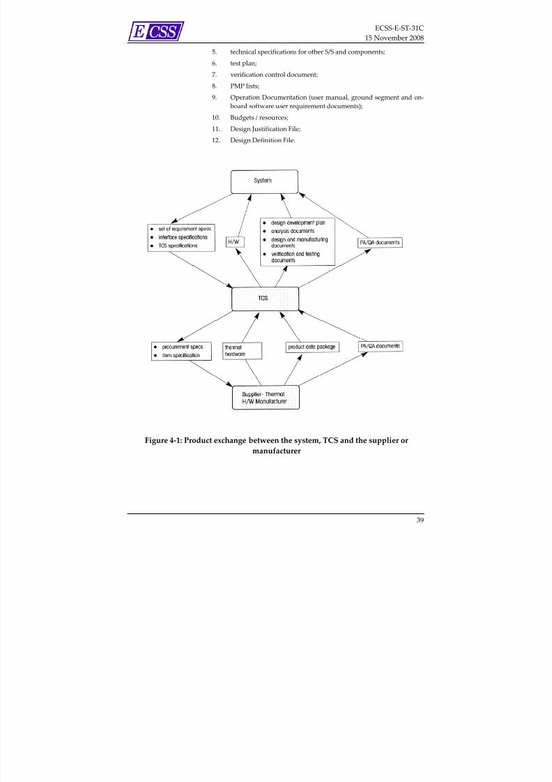
Figure 4-1: Product exchange between the system, TCS and the supplier ormanufacturer........................................................................................................39
Tables
Table 5-1: ECSS-E-ST-31 DRD list........................................................................................42
Table G-1 : Definitions and requirements for the cryogenic temperature range used inthis Standard........................................................................................................63
Table H-1 : Definitions and requirements for the high temperature range used in thisStandard .............................................................................................................. 64
6

7/22/2019 Ecss e St 31c(15november2008)
http://slidepdf.com/reader/full/ecss-e-st-31c15november2008 7/65
ECSS‐E‐ST‐31C
15 November 2008
1Scope
ECSS‐E‐ST‐31 defines requirements for the discipline of thermal engineering.
This Standard defines the requirements for the definition, analysis, design,
manufacture, verification and in‐service operation of thermal control
subsystems of spacecraft and other space products.
For this Standard, the complete temperature scale is divided into three ranges:
• Cryogenic temperature range
• Conventional temperature range
• High temperature range.
The requirements of this Standard are applicable to the complete temperature
scale. However, where applicable, requirements are stated to be applicable only
for the cryogenic or high temperature range. References to these specific
requirements have been summarized in Annex G and Annex H.
This standard
is
applicable
to
all
flight
hardware
of
space
projects,
including
spacecraft and launchers.
This standard may be tailored for the specific characteristic and constrains of a
space project in conformance with ECSS‐S‐ST‐00.
7
7/22/2019 Ecss e St 31c(15november2008)
http://slidepdf.com/reader/full/ecss-e-st-31c15november2008 8/65
ECSS‐E‐ST‐31C
15 November 2008
2Normative references
The following normative documents contain provisions which, through
reference in this text, constitute provisions of this ECSS Standard. For dated
references, subsequent amendments to, or revision of any of these publications
do not apply, However, parties to agreements based on this ECSS Standard are
encouraged to
investigate
the
possibility
of
applying
the
more
recent
editions
of
the normative documents indicated below. For undated references, the latest
edition of the publication referred to applies.
ECSS‐S‐ST‐00‐01 ECSS system – Glossary of terms
ECSS‐E‐ST‐10‐02 Space engineering – Verification
ECSS‐E‐ST‐10‐03 Space engineering – Testing
ECSS‐E‐ST‐10‐04 Space engineering – Space environment
ECSS‐M‐ST‐40 Space project management – Configuration and
information management
ECSS‐Q‐ST‐20 Space product assurance – Quality assurance
ECSS‐Q‐ST‐40 Space product assurance – Safety
ECSS‐Q‐ST‐70 Space product assurance – Materials, mechanical
parts and processes
ECSS‐Q‐ST‐70‐01 Space product assurance – Cleanliness and
contamination control
8
7/22/2019 Ecss e St 31c(15november2008)
http://slidepdf.com/reader/full/ecss-e-st-31c15november2008 9/65
ECSS‐E‐ST‐31C
15 November 2008
3Terms, definitions and abbreviated terms
3.1 Terms from other standards
For the purpose of this Standard, the terms and definitions from ECSS‐ST‐00‐01
apply, in particular for the following terms:
acceptance test
(system
level)
assembly
item
part
For the purpose of this Standard, the following terms and definitions from
ECSS‐E‐ST‐10‐03 apply:
temperature cycle
3.2 Terms specific to the present standard
3.2.1 General
3.2.1.1 acceptance margin
contingency agreed between system authority and TCS to account for
unpredictable TCS‐related events
NOTE The acceptance margin is the difference
between the upper or lower acceptance
temperature and the upper or lower design
temperature
(for
both
operating
and
non ‐operating mode). See Figure 3‐1.
9

7/22/2019 Ecss e St 31c(15november2008)
http://slidepdf.com/reader/full/ecss-e-st-31c15november2008 10/65
ECSS‐E‐ST‐31C
15 November 2008
Figure 3‐1: Temperature definitions for thermal control system (TCS)
3.2.1.2 acceptance temperature range
temperature range obtained from the qualification temperature range after
subtraction of qualification margins specified for the operating and non‐
operating mode and the switch‐on condition of a unit
NOTE 1 The acceptance temperature range is the extreme
temperature range
that
a unit
can
reach,
but
never
exceed, during all envisaged mission phases
(based on worst case assumptions). See Figure 3‐1.
NOTE 2 Temperature range used during acceptance tests to
verify specified requirements and workmanship
3.2.1.3 calculated temperature range
temperature range obtained by analysis or other means for the operating and
non‐operating mode and the minimum switch‐on condition of a unit, based on
worst case considerations (i.e. an appropriate combination of external fluxes,
materials properties and unit dissipation profiles to describe hot and cold
conditions) excluding
failure
cases
NOTE See Figure 3‐1. The calculated temperature
range plus any uncertainties is limited to the
specified design temperature range. During the
course of a project these uncertainties change
from initial estimates into a value determined
by analysis.
3.2.1.4 climatic test
test conducted to demonstrate the capability of an item to operate satisfactorily
or to survive without degradation under specific environmental conditions at
predefined hot and cold temperatures, temperature gradients and temperature
variations
10

7/22/2019 Ecss e St 31c(15november2008)
http://slidepdf.com/reader/full/ecss-e-st-31c15november2008 11/65
ECSS‐E‐ST‐31C
15 November 2008
NOTE Examples of environmental conditions are:
pressure, humidity and composition of
atmosphere.
3.2.1.5 thermal component
piece of
thermal
hardware
which
by
further
subdivision
loses
its
functionality,
but is not necessarily destroyed
3.2.1.6 correlation
correspondence between analytical predictions and test results
3.2.1.7 design temperature range
temperature range specified for the operating and non‐operating mode and the
switch‐on condition of a unit, obtained by subtracting acceptance margins from
the acceptance temperature range
NOTE 1 Temperature range representing the temperature
requirement
for
the
TCS
design
activities.
NOTE 2 The terms “operating temperature range” or
“operational temperature range” should not be
used for the design temperature range. The term
“operating or non‐operating temperature limits” is
acceptable.
3.2.1.8 geometr ical mathematical model (GMM)
mathematical model in which an item and its surroundings are represented by
radiation exchanging surfaces characterised by their thermo‐optical properties
NOTE The GMM generates the absorbed
environmental heat fluxes and the radiative
couplings between the surfaces.
3.2.1.9 heat dissipation
thermal energy divided by time produced by a source
3.2.1.10 heat flux
thermal energy (heat) divided by time and unit area perpendicular to the flow
path
NOTE Heat flux is also referred to as heat flow rate
density.
3.2.1.11 heat leak
unwanted heat exchange between a thermally protected item and the
environment
NOTE The heat leak can be a heat gain or a heat loss
depending of the environmental temperature
3.2.1.12 heat li ft
transfer of a specified heat flow rate from a lower to a higher temperature
NOTE For example: Heat pump.
11
7/22/2019 Ecss e St 31c(15november2008)
http://slidepdf.com/reader/full/ecss-e-st-31c15november2008 12/65
ECSS‐E‐ST‐31C
15 November 2008
3.2.1.13 heat storage
capability to store heat at a defined temperature or within a defined
temperature range
NOTE For example: Heat storage can be performed by
sensible
heat,
latent
heat
as
a
PCM, by
heat
conversion into chemical energy.
3.2.1.14 induced environment
set of environmental conditions for a given item created by the operation or
movement of the item itself
NOTE For example: Set of loading conditions due to
atmospheric flight.
3.2.1.15 inf rared test
thermal test method in which the solar and planetary radiation and
aerodynamic heating
are
simulated
by
locally
heating
the
spacecraft
surface
to
the predicted input level using infrared techniques
NOTE For example: Infrared lamps and heaters.
3.2.1.16 min imum swi tch-on temperature
minimum temperature at which a unit can be switched from the non‐operating
mode to the operating mode and functions nominally when the unit
temperature is brought back to the relevant operating mode temperatures
NOTE Also referred to as start‐up temperature.
3.2.1.17 natural environment
set of environmental conditions defined by the external physical surrounding
for a certain mission
NOTE For example: Heat flux by sun and planet, gas
composition and pressure of planet
atmosphere.
3.2.1.18 predicted temperature range
temperature range obtained from the calculated temperature range increased
by the uncertainties
NOTE See Figure 3‐1
3.2.1.19 quali fication margin
contingency approved by the system authority to account for any unexpected
events
NOTE For temperatures, the qualification margin is
the difference between the upper or lower
qualification temperature and the upper or
lower acceptance temperature (for operating
and non ‐operating mode). See Figure 3‐1.
12

7/22/2019 Ecss e St 31c(15november2008)
http://slidepdf.com/reader/full/ecss-e-st-31c15november2008 13/65
ECSS‐E‐ST‐31C
15 November 2008
3.2.1.20 quali fication temperature range
temperature range specified for the operating and non‐operating mode and the
switch‐on condition of a unit, for which this unit is guaranteed to fulfil all
specified requirements
NOTE
See Figure
3‐1.
3.2.1.21 quali fication test (system level)
verification process that demonstrates that hardware fulfil all specified
requirements under simulated conditions more severe than those expected
during the mission
NOTE During the qualification tests, unit temperature
reference points (TRP) are exposed to
temperatures within but not exceeding the
qualification temperature range.
3.2.1.22 radiative sink temperature
virtual black body radiation temperature used to define the equivalent radiative
thermal load on an item
NOTE 1 The radiative sink temperature includes both the
natural environment load (solar, planetary albedo
and infrared fluxes) and the radiative exchanges
with other items.
NOTE 2 The radiative sink temperature is typically used to
provide a simplified interface for an item, to
provide a means for parameter studies thus
avoiding extensive calculations or to define
adequate radiative boundary conditions for
thermal tests.
NOTE 3 The sink temperature T Sink of an item i with a
temperature T i in radiative exchange with n items j
and submitted to external radiative environmental
fluxes is calculated according to the formula:
4 1
44
4
,
)(
)(i
IR
i
A
i
s
i
n
j
i jij
irad Sink A
P
A
P
A
P
A
T T R
T iT σε σε σε
+++∈
−
+=
∑=
where
emissivity of item i
Ps absorbed solar flux on item i
P A absorbed (planetary) albedo flux on item i
P IR absorbed infrared (planetary) flux on item i
Rij radiative coupling between item i and item j
T j temperature of item j
σ Stefan‐Boltzmann constant
Ai
radiative exchange
area
of
item i
13

7/22/2019 Ecss e St 31c(15november2008)
http://slidepdf.com/reader/full/ecss-e-st-31c15november2008 14/65
ECSS‐E‐ST‐31C
15 November 2008
NOTE 4 The radiative sink temperature formula is defined
for steady state and transient conditions.
Depending on the degree of interaction between
the item i (via its temperature, surface properties,
dimensions, heat dissipation) and the radiative
sink,
the
simplified
approach
using
the
radiative
sink temperature is performed in an iterative way
during the course of a project.
3.2.1.23 sensi tiv ity analysis
analysis, which uses a variation of input parameters in order to evaluate the
influence of inaccuracies on the analysis results
3.2.1.24 solar simulation test
test method in which the intensity, spectral distribution, uniformity and
collimation angle of the solar radiation are reproduced within acceptable limits
3.2.1.25 success cri teria
predefined value or set of values used for verification of a requirement and
based on one or several parameters
NOTE 1 Success criteria can be defined for verification by
analysis and test.
NOTE 2 Examples of such parameters are temperature, and
temperature gradient.
3.2.1.26 system authority
organization responsible for the system
NOTE The s̋ystem authorityʺ can be the c̋ustomerʺ as
defined in ECSS‐S‐ST‐00‐01.
3.2.1.27 system interface temperature point
physical point appropriately located on the structure of the system which can
be used to evaluate the heat exchanged by conduction between a unit and the
spacecraft system 3.2.1.28 temperature dif ference
difference in temperature of two points at a given time
3.2.1.29 temperature gradient
spatial derivation of temperature in a point at a given time
NOTE It is expressed by a temperature divided by unit
length.
3.2.1.30 temperature mean deviation ( Tmean)
sum of temperature differences (measured minus analysed values) divided by
the number of correlated temperatures
NOTE ΔTmean can be positive or negative.
ΔT mean =1
N
T Mi − T Pi( )i=1
N
∑
where
14
7/22/2019 Ecss e St 31c(15november2008)
http://slidepdf.com/reader/full/ecss-e-st-31c15november2008 15/65
ECSS‐E‐ST‐31C
15 November 2008
ΔTmean = temperature mean deviation
TMi = measured temperature
TPi = temperature predicted by analysis
N = number of samples
3.2.1.31 temperature reference point (TRP)
physical point located on a unit and defined in the unit ICD to provide a
simplified representation of the unit temperature
NOTE 1 The TRP is used for coherent verification at unit,
subsystem and system level.
NOTE 2 Depending on the unit dimensions and interface
complexity, more than one temperature reference
point can be defined.
3.2.1.32 temperature stabi lit y
condition when
the
temperature
variation
for
a defined
period
of
time
is
less
than a defined (small) value
3.2.1.33 temperature standard deviation ( )
measure of statistical dispersion of temperature deviations, measuring how
widely spread the values of temperature differences in a data set are
NOTE Temperature standard deviation is given by:
σ =1
N − 1T Mi − T Pi( )− ΔT mean[ ]
2
i=1
N
∑
where
TMi = measured temperature
TPi = temperature predicted by analysis
ΔTmean = temperature mean deviation (see 3.2.1.30)
N = number of samples.
3.2.1.34 temperature uni formity
condition when the temperature difference or the temperature gradient at a
given time is less than a defined (small) value
3.2.1.35 temperature variation
change of temperature at a given point with respect to time
NOTE It is expressed by a temperature divided by
time.
3.2.1.36 thermal balance test
test conducted to verify the adequacy of the thermal model and the adequacy of
the thermal design
3.2.1.37 thermal design case
set of parameters used for the definition and sizing of the thermal control
subsystem
15

7/22/2019 Ecss e St 31c(15november2008)
http://slidepdf.com/reader/full/ecss-e-st-31c15november2008 16/65
ECSS‐E‐ST‐31C
15 November 2008
NOTE For example: environmental, material
properties and dissipation profiles are typical
set of parameters.
3.2.1.38 thermal mathematical model (TMM)
numerical
representation
of
an
item
and
its
surroundings
represented
by
concentrated thermal capacitance nodes or elements, coupled by a network
made of thermal conductors (radiative, conductive and convective)
NOTE 1 For thermo ‐ hydraulic modelling enthalpy and
fluidic conductors are used in addition.
NOTE 2 A TMM generates for all nodes / elements a
temperature history, an energy balance; in
addition pressure drops and mass flow rates for
thermo ‐hydraulic modelling.
NOTE 3 Numerical representation can be performed by
lumped parameter, finite difference or finite
element methods.
3.2.1.39 thermal node
representation of a specific volume of an item with a representative
temperature, representative material properties and representative pressure
(diffusion node) used in a mathematical lumped parameter approach
3.2.1.40 thermal vacuum test
test conducted to demonstrate the capability of the test item to operate
according to requirements in vacuum at predefined temperature condition
NOTE Temperature conditions can be expressed as
temperature level, gradient and variation.
3.2.1.41 uncertainties
inaccuracies in temperature calculations due to inaccurate physical,
environmental and modelling parameters
3.2.1.42 unit
finished product with a given internal design
NOTE 1 The only interaction between a unit and TCS is via
the control of external means (e.g. surface coatings,
mounting method) and temperature information is
derived from the temperature at the unit
temperature reference point
NOTE 2 All data relevant for TCS are included in an
interface control document (ICD).
3.2.2 Unit internal thermal design
3.2.2.1 uni t acceptance test temperature range
extreme range which is used for acceptance at unit level
NOTE See Figure 3‐2. The unit acceptance temperature
range is obtained from the (TCS) acceptance
16

7/22/2019 Ecss e St 31c(15november2008)
http://slidepdf.com/reader/full/ecss-e-st-31c15november2008 17/65
ECSS‐E‐ST‐31C
15 November 2008
temperature range as defined in Figure 3‐1 after
the addition of a suitable value to account for
test inaccuracies.
Figure 3‐2: Temperature definitions for unit thermal design
3.2.2.2 uni t internal design temperature range
extreme range for which components or parts are selected
NOTE See Figure 3‐2. Unit internal design
temperatures are derived from unit thermal
calculations including uncertainties and
margins.
3.2.2.3 unit qualification test temperature range
extreme range used for unit qualification at unit level
NOTE See Figure 3‐2. The unit qualification
temperature range is obtained from the
qualification temperature range as defined in
Figure 3‐1 after addition of a suitable value to
account for test inaccuracies.
3.2.3 Cryogenic temperature range
3.2.3.1 cryogenic temperature range
temperature range below 200 K
3.2.3.2 cryogenic contro l system (CCS)
system which provides thermal control in the cryogenic temperature range
NOTE The CCS provides either bulk or point cooling
with defined interfaces for assessing the
cryogenic heat load on the CCS.
17

7/22/2019 Ecss e St 31c(15november2008)
http://slidepdf.com/reader/full/ecss-e-st-31c15november2008 18/65
ECSS‐E‐ST‐31C
15 November 2008
3.2.3.3 maximum cryogenic heat load
sum of all heat flowing into the cold side of the CCS for the most unfavourable
conditions
NOTE For example: All heaters and sensors energized
and mechanisms
operating.
3.2.3.4 maximum cryogenic temperature
temperature of a defined item when the total heat load flowing into the CCS is
the maximum cryogenic heat load and considering the worst case performance
of the CCS
3.2.3.5 nominal cryogenic heat load
sum of all heat flowing into the cold side of the CCS in a nominal steady state
operation
3.2.3.6 nominal cryogenic temperature
temperature of a defined item when the total heat load flowing into the CCS in
nominal steady state conditions is the nominal cryogenic heat load and
considering a nominal performance of the CCS
3.2.3.7 ult imate cryogenic heat load
maximum cryogenic heat load multiplied by a safety coefficient agreed by the
system authority and depending on the design status
3.2.3.8 ult imate cryogenic temperature
maximum cryogenic temperature increased by the temperature margins agreed
by the system authority and depending on the design status
3.2.4 High temperature range
3.2.4.1 high temperature range
temperature range above 470 K
3.2.4.2 ablation
chemical change and removal of surface material due to the action of external
high temperature heating
NOTE Ablation consumes energy and provides a
cooling effect in the underlying material level.
3.2.4.3 aerodynamic heating
intense heating by convection, radiation and re‐combination effects, caused by
fluid compression, typically occurring during atmospheric entry
3.2.4.4 allowable temperatures
maximum temperatures specified for thermally protected items to ensure the
structure integrity
NOTE For example: Protected items are primary and
secondary structures.
18
7/22/2019 Ecss e St 31c(15november2008)
http://slidepdf.com/reader/full/ecss-e-st-31c15november2008 19/65
ECSS‐E‐ST‐31C
15 November 2008
3.2.4.5 arc-jet test
testing method using electric discharge to produce a plasma
3.2.4.6 combined loads
combination of thermal and mechanical loads acting simultaneously on the TPS
3.2.4.7 hot structure
primary mechanical load carrying structure which is directly exposed to the
high temperatures caused by aerodynamic flow
NOTE For example: Heat shield, nose cap, wing
leading edges, control surfaces such as winglet,
rudder and body‐flap.
3.2.4.8 limit aero-thermal heat flux
maximum or minimum local heat flux values, or the most unfavourable
simultaneous combination of the constituting terms (in the sense of
maximizing‐ or minimizing these heat fluxes) liable to be attained in the
different areas of the vehicle during the normal service life for the
corresponding mission instant
NOTE 1 Limit aero‐thermal heat flux applies to TPS and
hot structures only.
NOTE 2 Aero‐thermal fluxes can be caused by molecular
flow and can also act after fairing jettisoning or at
very low attitudes at orbital velocities.
3.2.4.9 limit temperatures
maximum or minimum local temperatures of an exposed surface for a defined
item resulting from the application of the least favourable heat fluxes histories
expected on nominal missions inside the boundaries of limit fluxes
3.2.4.10 nominal aero-thermal heat fluxes
nominal local heat flux values expected for nominal mission and nominal
atmospheric conditions
NOTE Nominal aero‐thermal heat flux applies to TPS
and hot structures only.
3.2.4.11 nominal temperatures
local temperatures of an exposed surface for a defined item resulting from the
application of the nominal heat flux histories
3.2.4.12 plasma wind-tunnel
test method using a high temperature ionized medium flowing over the test
item
3.2.4.13 protected structure
primary mechanical load carrying structure which is covered by a thermal
protection layer exposed to the aerodynamic flow
3.2.4.14 thermal protection subsystem (TPS)
thermal control system to protect the spacecraft against aerodynamic heating
19

7/22/2019 Ecss e St 31c(15november2008)
http://slidepdf.com/reader/full/ecss-e-st-31c15november2008 20/65
ECSS‐E‐ST‐31C
15 November 2008
NOTE For example: Ablative materials, ceramic tile
and shingle, CMC stand‐off panel TPS, metallic
TPS, flexible external insulation blanket,
internal insulation, high temperature static and
dynamic seals, high temperature assembly
systems (i.e.
tribology,
hot
fasteners).
3.2.4.15 ult imate aero-thermal heat fluxes
heat fluxes deduced from the limit heat fluxes upper boundary values through
aero‐convective upper boundary limit heat fluxes (launch and re‐entry)
multiplied by a safety coefficient
NOTE Ultimate aero‐thermal heat flux applies to TPS
and hot structures only.
3.2.4.16 ult imate temperature
local instantaneous temperature of an exposed surface for a defined item
resulting from the application of ultimate flux histories
3.3 Abbreviated terms
For the purpose of this Standard, the abbreviated terms from ECSS‐S‐ST‐00‐01
and the following apply:
Abbreviation Meaning
ABM apogee boost motor
AIT assembly, integration and test
AOCS attitude and orbit control system
CCS cryogenic control system
CMC ceramic matrix composites
DRD document requirements definition
DRL document requirements list
ECLS environmental control and life support system
EEE electronic, electrical, electromechanical
EM engineering model
EMC electromagnetic compatibility
ESD electrostatic discharge
FAR flight acceptance review
FEM finite element methods
FM flight model
FOV field of view
GMM geometrical mathematical model
GSE ground support equipment
20
7/22/2019 Ecss e St 31c(15november2008)
http://slidepdf.com/reader/full/ecss-e-st-31c15november2008 21/65
ECSS‐E‐ST‐31C
15 November 2008
H/W hardware
HS hot structure
I/F interface
ICD interface control document
LEO low Earth orbit
LHP loop heat pipe
LPM lumped parameter method
MLI multi layer insulation
OBDH on‐ board data handling
PA product assurance
PCM phase change material
PMP parts, materials, process
QA quality assurance
QM qualification model
RLV reusable launch vehicle
RV re‐entry vehicle
S/C spacecraft
S/W software
STM structural thermal model
TBT
thermal balance
test
TC thermocouple
TCS thermal control (sub)system
TM thermal model
TM/TC telemetry, telecommand
TMM thermal mathematical model
TPS thermal protection system
TRP temperature reference point
TV‐Test
thermal
‐vacuum
test
VCHP variable conductance heat pipe
w.r.t. with respect to
21

7/22/2019 Ecss e St 31c(15november2008)
http://slidepdf.com/reader/full/ecss-e-st-31c15november2008 22/65
ECSS‐E‐ST‐31C
15 November 2008
4Requirements
4.1 Mission
4.1.1 General
a. The
design
of
the
TCS
shall
meet
requirements
of
all
mission
phases,
up
to the end of the operating lifetime.
NOTE The specified environmental conditions are
usually found in the system environmental
specification.
4.1.2 Ground and pre-launch
a. The following conditions shall apply:
1. integration and ground testing;
2. storage, transport;
3. functional check‐out;
4. waiting on launch pad;
5. launch abort.
b. Thermal constraints related to the ground and pre‐launch phases shall be
agreed with the system authority and specified in Phase A of a project.
c. Space vehicle and GSE design shall accommodate specific requirements
for thermal conditioning.
NOTE For example: Battery thermal conditioning, heat
pipe panel levelling fixtures, auxiliary fluid
cooling loops, pre‐launch conditioning of
launcher.
4.1.3 Launch and ascent
a. The following conditions shall apply:
1. worst case launcher boundary conditions (launch time and season;
external environment);
2. impact of depressurization;
3. launch abort conditions;
4. spacecraft under fairing;
22

7/22/2019 Ecss e St 31c(15november2008)
http://slidepdf.com/reader/full/ecss-e-st-31c15november2008 23/65
ECSS‐E‐ST‐31C
15 November 2008
5. environment after fairing jettisoning up to separation (aero‐
thermal fluxes, solar and planetary fluxes, eclipses);
6. ABM firing.
b. Thermal requirements related to the launch and ascent phases shall be
specified.
4.1.4 Planetary orbital phases
a. The TCS design shall use the following parameters, which relate to
transfer, drift, commissioning and operational orbits:
1. orbit radii (or heights) and eccentricity including its evolution in
time;
2. inclination and its evolution in time;
3. ascending node angle and its evolution in time;
4. maximum eclipse duration or argument of perigee;
5. spacecraft orientation, w.r.t. sun, planet;
6. relative movement of spacecraft items with respect to the main
spacecraft body.
NOTE Examples of main spacecraft bodies are: solar
array, and antennae.
4.1.5 Interplanetary phases
a. The TCS design shall use the following parameters for interplanetary
phases:
1. Spacecraft orientation w.r.t. external heat sources
NOTE Example of external heat sources are: sun, and
planets.
2. Relative movement of spacecraft items with respect to the main
spacecraft body.
NOTE Examples of such spacecraft items are: solar
array, and antennae.
4.1.6 Planetary natural environmenta. For earth and sun the natural environment as specified in ECSS‐E‐10‐04,
clause 6 shall apply.
b. For bodies other than the earth, the applicable natural environment shall
be agreed with the system authority.
4.1.7 Docking, docked and separation phases
a. The TCS shall be designed for mission aspects during docking and
separation manoeuvre as well as during a docked phase, including the
following conditions:
1. spacecraft orientation;
23

7/22/2019 Ecss e St 31c(15november2008)
http://slidepdf.com/reader/full/ecss-e-st-31c15november2008 24/65
ECSS‐E‐ST‐31C
15 November 2008
2. firing of thrusters;
3. shadowing effects;
4. mutual radiative heat exchanges;
5. reflected environmental fluxes;
6. multiple reflections.
4.1.8 Descent, entry and landing
a. The TCS shall be designed for heat flux effects as well as transient
phenomena during descent, entry and landing including:
1. loss of MLI efficiency due to re‐pressurization;
2. heating and cooling effects due to the inlet of air and gas for re‐
pressurization;
3. requirement for special heat sinks during descent.
4.1.9 Post-landing phases
a. The TCS design shall conform to the environmental conditions occurring
at the landing site.
b. The TCS design shall include thermal conditioning during the post‐
landing phases.
NOTE For example: specific GSE.
c. The TCS design shall account for the heat load stored by the TPS during
entry phases.
4.2 Performance
4.2.1 General
a. TCS performance requirements for all mission phases shall be specified
and agreed with the system authority.
b. The mission phases shall be represented by a coherent set of thermal
design cases covering the extreme range of conditions experienced by an
item during
its
lifetime.
c. Dimensioning environmental design cases shall be defined and used for
the development of the TCS design.
d. For the dimensioning environmental design cases hot and cold worst
cases shall be used.
e. Minimum and maximum values for design temperatures shall be
provided by the system authority.
f. Acceptance and qualification margins as defined in Figure 3‐1 shall be
defined by the system authority.
g. The TCS shall conform to the following requirements to be specified in
the TCS specification:
24

7/22/2019 Ecss e St 31c(15november2008)
http://slidepdf.com/reader/full/ecss-e-st-31c15november2008 25/65
ECSS‐E‐ST‐31C
15 November 2008
1. Temperature gradients
2. Temperature stability
3. Temperature uniformity
4. Heat flux
5. Heat storage
6. Heat lift
7. Electrical power allocation for heating and cooling
8. TM/TC allocation for TCS parameter;
NOTE For requirements on TM/TC, see 4.3.5.
9. Mass allocation for TCS.
4.2.2 High temperature rangea. Temperatures of all protected items shall not exceed the allowable
temperatures defined by the system authority and specified in the TCS
specification.
b. A TPS in the high temperature range shall:
1. Respect the aero thermodynamic shape of the space vehicle.
NOTE For example: Steps, gaps, and roughness
tolerances.
2. Insulate the space vehicle to withstand the outer temperature
range, limit temperature levels, temperature gradients and heat flows on the protected elements.
3. Support mechanical and thermo‐mechanical loads.
4. Include venting in order to withstand the pressure decrease and
increase encountered during ascent and re‐entry.
5. Avoid hot gas ingress (i.e. aero thermodynamic sneak flows) into
structure and internal equipments.
6. Withstand on‐ground and in‐orbit natural environments.
NOTE 1 For reusable re‐entry vehicles additional
requirements for on‐ground and in‐orbit maintenance (inspection, repair and replacement)
can be specified at system level.
NOTE 2 For fracture control requirements see ECSS‐E‐ST‐
32‐01 and fracture control DRDs in ECSS‐E‐ST‐32.
NOTE 3 For re‐usable TPS cases the number of ascent/entry
cycles need to be specified.
4.2.3 Cryogenic temperature range
a. The Cryogenic Control System (CCS) shall meet the allowable
temperatures defined by the system authority and specified in the CCS
specification.
25
7/22/2019 Ecss e St 31c(15november2008)
http://slidepdf.com/reader/full/ecss-e-st-31c15november2008 26/65
ECSS‐E‐ST‐31C
15 November 2008
b. For the design of the CCS radiators, the ultimate cryogenic temperature
shall be applied.
c. For the design of the CCS stirling and pulse tube coolers, the ultimate
cryogenic heat load shall be applied.
d. For
the
design
of
the
CCS
all
other
coolers
and
cooling
chains,
the
application of the ultimate cryogenic heat load or ultimate cryogenic
temperature shall be defined for each thermal I/F and agreed with the
system authority.
e. The CCS design shall meet requirements for cool down from non‐
operating maximum temperature down to nominal cryogenic
temperatures
4.2.4 Functionality
a. Functional requirements for the TCS shall be specified at system level.
NOTE For example: Function in any orientation, under specified gravity and acceleration environment.
4.3 Requirements towards other subsystems
4.3.1 General
a. The following requirements shall be agreed and included in the TCS
specification:
1. requirements from
other
subsystems
affecting
the
TCS;
2. requirements from TCS on other subsystems.
b. Requirements shall be defined in the TCS interface control document in
conformance with the DRD of Annex D.
c. The TCS interface control document shall be delivered to the system
authority for approval.
4.3.2 Mechanical
a. The TCS shall be designed respecting spacecraft configuration and
layout,
including
the
following
information
for
each
item
in
the
applicable ICD:
1. Dimension and mass
2. Materials and heat capacities
3. Fixation and mounting techniques
4. Contact area
5. Surface characteristics
NOTE For example: Treatment, planarity and
roughness.
6. Alignment requirements
26

7/22/2019 Ecss e St 31c(15november2008)
http://slidepdf.com/reader/full/ecss-e-st-31c15november2008 27/65
ECSS‐E‐ST‐31C
15 November 2008
7. Forbidden zones
NOTE For example: instrument FOV and operational
range of mechanism.
8. Connector locations
9. Available area for fixation of thermal hardware
NOTE For example: heaters and MLI.
10. Spacecraft harness.
NOTE In case of an unacceptable or unbalanced
concentration of heat dissipation, the TCS can
propose changes to the spacecraft configuration
layout.
b. The TCS shall conform to mechanical loads during mission phases as
identified by structural analysis.
NOTE Mechanical stability requirements are specified
at system level.
c. The TCS hardware configuration and layout shall be defined in the
thermal ICD, including TCS specific forbidden zones.
NOTE 1 For example, unobstructed radiation to space, and
radiator deployment range.
NOTE 2 For the TCS ICD, see Annex D.
4.3.3 Electrical
a. The TCS
shall
fulfil
specific
requirements
considering
the
heat
dissipation
profiles of all items on the spacecraft including energy dissipated in any
cabling;
b. The TCS shall fulfil specific requirements considering type and routing of
the harness, grounding, electrical conductivity.
NOTE Propose changes to the layout, routing, and
external wrapping of any harness and cabling,
so as to avoid unacceptable or unbalanced
concentration of heat dissipation;
c. The TCS shall specify for electrical TCS items the power consumption,
peak and average power, duty cycle
d. The TCS shall comply with the specified voltage and voltage variation;
e. The TCS shall meet grounding and EMC requirements for TCS items.
4.3.4 AOCS
4.3.4.1 Propulsion
a. The TCS design shall fulfil requirements considering heat fluxes due to
plume interaction and the temperature profiles of the thruster
components during operation of a thrusters.
27
7/22/2019 Ecss e St 31c(15november2008)
http://slidepdf.com/reader/full/ecss-e-st-31c15november2008 28/65
ECSS‐E‐ST‐31C
15 November 2008
NOTE Examples of thruster components are: nozzle,
and heat shield.
b. The TCS shall be designed for effects of heat soak after firing of thrusters.
c. TCS shall agree with the system authority modifications of thruster
operation
for
the
case
that
temperatures
of
thruster
components
are
predicted to be not acceptable.
4.3.4.2 Att itude control
a. Attitude requirements affecting the TCS design shall be specified at
system level.
NOTE For example: Specified momentum for
mechanical pumps in fluid loops.
b. In case of a thermally unacceptable attitude, the TCS shall agree with the
system authority alternative attitudes and lay out.
4.3.5 TM/TC
a. TM/TC channel requirements allocated to the TCS shall be specified at
system level.
NOTE Requirements can include accuracy,
measurement frequency, downlink or uplink
frequency, on‐ board or ground data handling
and override capability
b. The TCS shall specify:
1. The telemetry channels to monitor spacecraft temperatures, TCS
temperatures, pressures, flow rates, voltages. currents, and switch
status.
NOTE For example: Voltage for heaters, or currents for
Peltier elements.
2. All ground or onboard controlled telecommand channels for the
operation of the TCS.
4.3.6 OBDH and S/W
a. TCS
related
OBDH
and
software
requirements,
and
requirements
to
implement TCS features into the data handling subsystem, shall be
specified by the TCS and agreed with the system authority.
NOTE For example: Heater control laws, and
temperature sensor calibration data.
4.3.7 Launcher
a. TCS shall derive and agree with the system authority requirements
related to the launcher interface based on the launcher ICD.
NOTE This is particularly important for:
28

7/22/2019 Ecss e St 31c(15november2008)
http://slidepdf.com/reader/full/ecss-e-st-31c15november2008 29/65
ECSS‐E‐ST‐31C
15 November 2008
• launcher envelope both for static and
dynamic conditions, including ventilation
effects;
• accessibility requirements;
• launch‐pad air ‐conditioning requirements;
• launcher depressurization profile;
• heat fluxes from the fairing and to the
launcher interface;
• heat flux from the spacecraft to the launcher.
4.3.8 GSE
a. GSE interface requirements related to TCS shall be specified in the GSE
specification of the project.
b. TCS specific requirements for ground support equipment shall be
specified by the thermal control subsystem.
c. The TCS design shall permit GSEs to interface the S/C at the specified
locations.
4.3.9 ECLS
a. The TCS shall conform to requirements of ECLS.
4.4 Design
4.4.1 General
a. The TCS design shall meet the thermal mission requirements of
clause 4.1 , the thermal performance requirements of clause 4.2 , the
interface requirements to other subsystems of 4.3.
b. The TCS design shall make use of materials and design features
compatible with the environmental factors expected during all mission
phases including possible effects and degradations.
NOTE Degradation can be caused by wear, mechanical
loads, test environment, and in‐orbit
environment (e.g. ATOX, UV, and radiation).
c. The TCS design shall be documented in the TCS detailed design
document in conformance with the DRD of Annex F.
d. Reliable properties of materials and their degraded values under the
specified environment shall be used in the design.
e. If suitable data are not available, then a material test programme shall be
implemented.
29
7/22/2019 Ecss e St 31c(15november2008)
http://slidepdf.com/reader/full/ecss-e-st-31c15november2008 30/65
ECSS‐E‐ST‐31C
15 November 2008
4.4.2 Budget allocation
a. The TCS shall define for system approval budgets for mass, size, power,
energy, TM/TC channels and operational aspects throughout the TCS life
cycle.
4.4.3 Parts, materials and processes (PMP)
a. The TCS design shall use space qualified parts, materials and processes.
NOTE For example: Preferred PMP list.
b. An acceptance or qualification programme shall be performed in
agreement with the system authority for parts, materials or processes,
which have not yet reached a space‐qualification status.
c. Declared materials, mechanical parts and processes lists shall be
produced according to the Declared material list (DML) DRD specified in
ECSS‐Q‐ST‐70.
4.4.4 EEE components
a. The TCS design shall use space qualified EEE components.
b. An acceptance or qualification programme shall be performed in
agreement with the system authority for EEE components, which have
not yet reached a space‐qualification status.
4.4.5 Lifetime
a. The TCS design shall conform to the total lifetime covering expected
combinations of
the
mission
phases.
4.4.6 Predictability and testabili ty
a. The TCS shall be designed such that conformance to performance
requirements of clause 4.2 can be demonstrated by thermal analyses and
thermal test.
NOTE Modularity of the TCS design can facilitate its
predictability and testability.
4.4.7 Flexibility
a. The TCS design shall incorporate flexibility to
1. accommodate modifications of requirements imposed on the TCS
during the project development phase;
2. offer trimming capabilities to accommodate late requirement
updates.
4.4.8 Integration and accessibil ity
a. Layout and design of the TCS hardware shall provide without
performance degradation accessibility to allow for integration,
mounting / de
‐mounting,
inspection
and
maintenance
of
items,
during
AIT and during flight.
30
7/22/2019 Ecss e St 31c(15november2008)
http://slidepdf.com/reader/full/ecss-e-st-31c15november2008 31/65
ECSS‐E‐ST‐31C
15 November 2008
4.4.9 Reliability
a. The allocated reliability figure for the TCS shall be specified at system
level.
b. The TCS shall demonstrate by analysis and test that the allocated
reliability figure is met.
c. Reliability requirements for the design of individual TCS items shall be
specified and verified.
NOTE These reliability requirements can be met by
introducing adequate redundancy features;
d. The TCS shall meet system requirements w.r.t. single point failures.
NOTE For the reduction of risk at subsystem level, see
ECSS‐M‐ST‐80 “Risk management”.
4.4.10 Interchangeabilitya. Interchangeability requirements to be met by TCS shall be specified at
system level.
4.4.11 Maintenance
a. The TCS shall specify maintenance procedures.
b. Operational maintenance during in‐orbit phases shall be avoided.
4.4.12 Safety
For safety,
see
ECSS
‐Q
‐ST
‐40.
For hazard analysis, see ECSS‐Q‐ST‐40‐02.
4.4.13 Availability
a. A plan for an in‐time availability of resources, including long lead items
and items with limited lifetime shall be agreed with the system authority.
4.5 Verification
4.5.1 Overview
For general requirements on verification of the TCS, see ECSS‐E‐ST‐10‐02 and
ECSS‐E‐ST‐10‐03.
4.5.2 Verif ication requirements specif ic to TCS
4.5.2.1 All temperature ranges
a. Verification by analysis shall be performed through thermal analytical
modelling and corresponding performance predictions.
b. The cases to be verified by analysis shall be agreed with the system
authority.
31

7/22/2019 Ecss e St 31c(15november2008)
http://slidepdf.com/reader/full/ecss-e-st-31c15november2008 32/65
ECSS‐E‐ST‐31C
15 November 2008
NOTE 1 Verification by analysis is the selected verification
method for cases where fully representative testing
cannot be performed.
NOTE 2 For example: Environmental and dimensional
limitations of the test facilities.
NOTE 3 For example: Behaviour of TCS items under
reduced or increased gravity.
c. Verification by analysis shall take into account uncertainties.
NOTE Uncertainties of lower than 10 K are generally
not applied before verification by a TBT is
performed.
d. Thermal and geometrical models shall be defined in a Mathematical
Model Specification in conformance with the DRD of Annex A.
e. Thermal and geometrical models used for analysis shall be documented
in the Thermal and Geometrical Model Description in conformance with
the DRD of Annex B.
f. For each thermal analysis a TCS analysis report shall be produced in
conformance with the DRD of Annex C.
g. Conformance to specified performance shall be demonstrated by
performing thermal balance, thermal vacuum and climatic tests.
h. Test conditions shall be agreed with the system authority and included in
the system test plan.
i. Verification testing of the TCS shall include, mechanical, electrical and
hydraulic testing
to
be
defined
in
test
specifications.
j. Temperatures at the TRP shall be used to verify requirements by analysis
and test.
4.5.2.2 CCS
a. A CCS shall be verified by testing at instrument and subsystem level.
b. Objectives and set‐up for tests on CCS shall be agreed with the system
authority and specified in the Verification Plan according to ECSS‐E‐ST‐
10‐02.
NOTE 1
Important inputs
for
the
test
objectives
are
the
CCS
interfaces.
NOTE 2 Testing at cryogenic temperatures is usually first
performed in a specialized laboratory.
4.5.2.3 High temperature TPS
a. Thermal tests on thermal protection items shall be agreed with the
system authority and specified in the Verification Plan in conformance
with its DRD specified in ECSS‐E‐ST‐10‐02.
b. Thermal protections shall be tested in association with the supporting
structure and equivalent mock‐ups (sub‐element), in order to provide
representative thermal interface conditions.
32
7/22/2019 Ecss e St 31c(15november2008)
http://slidepdf.com/reader/full/ecss-e-st-31c15november2008 33/65
ECSS‐E‐ST‐31C
15 November 2008
c. For the cases where full verification by test is not performed the
following requirements shall apply and agreed with the system
authority:
1. Introduction of simplified and separated test cases including
nominal and worst case scenarios.
2. Clear identification of unknown data and justification of
assumptions taken for test prediction.
NOTE Examples of unknown data: Heat flux,
catalycity, emissivity.
3. The methods and processes to use test results and extrapolate to
actual flight conditions.
NOTE 1 In addition to classical means, plasma wind‐tunnel
(e.g. arc‐ jet) and high temperature radiation test
methods may be used.
NOTE 2 This applies to cases, for which flight conditions are not sufficiently specified and where
verification by test is not appropriate (e.g. due to
the size of the test object or lack of environment
representativity).
4.5.3 Thermal balance test (TBT)
4.5.3.1 Test performance
a. TBT requirements shall be defined in the TCS thermal balance test
specification in
conformance
with
the
DRD
of
Annex
E.
b. TBT test procedures and test report shall be produced in conformance
with its DRDs specified in ECSS‐E‐ST‐10‐03 and ECSS‐ST‐E‐10‐02,
respectively.
c. For TCS items controlled by radiative and conductive heat exchange, a
thermal balance test shall be performed in order to:
1. provide data for the verification of the thermal mathematical
model as part of the TCS qualification,
2. demonstrate the suitability of the TCS design,
3.
verify
the
performance
of
TCS
hardware,
and
4. provide data about sensitivity of the TCS design with respect to
parameter changes.
NOTE 1 For example, heat dissipation
NOTE 2 TB testing is generally performed on items at high
integration levels, such as spacecraft, service
module, payload module or instruments.
d. The test instrumentation and the test set‐up to be used shall be defined in
the test specification (in conformance with Annex E) and agreed with the
system authority;
NOTE For example: Temperature sensors and heaters with adequate number and position.
33

7/22/2019 Ecss e St 31c(15november2008)
http://slidepdf.com/reader/full/ecss-e-st-31c15november2008 34/65
ECSS‐E‐ST‐31C
15 November 2008
e. The TBT shall provide accurate and reliable input data for the thermal
model correlation.
f. Analysis shall be performed to predict the thermal balance test results,
and documented in an analysis report in conformance with the DRD of
Annex C.
g. Two different steady‐state test cases shall be performed.
h. A transient case shall be included for items sensible to dynamic
behaviour.
i. The solar environment to be applied for solar simulation, and the cases
where solar simulation is used, shall be agreed with the system authority.
NOTE 1 Generally this is performed when the thermal
behaviour is governed by the solar environment
and the analytical verification poses unknown
uncertainties.
NOTE 2 For example: Items with complex geometry, shape, apertures and with specular reflective coatings.
j. Critical hardware items and interfaces shall be flight representative.
k. Parasitic radiative and conductive heat loads between test item and test
surroundings shall be determined and the influence on the test results
analytically verified.
4.5.3.2 Test success cri teria
a. For TBT the following test success criteria shall be applied:
1. Test conditions defined in the TBT specification specified in Annex
E , and TBT Procedure specified in the test procedure DRD of
ECSS‐E‐ST‐10‐03 are met.
2. Performance parameters as predicted by analysis for the TBT are
verified.
NOTE Example of performance parameters are
temperatures, temperature levels, gradients,
differences, and variations.
3. Resources specified in the TCS specification have not been
exceeded.
NOTE For example, heater power, battery energy in
an eclipse case.
b. Steady‐state condition shall be declared when for stable dissipation
modes temperature sensor readings meet a temperature variation over a
period of time defined in the TBT test procedure and agreed by the
system authority.
NOTE 1 Besides the classical TBT with steady state
conditions additional tests can be performed with
operating active heating / cooling regulation.
NOTE 2
For the
TBT
test
procedure,
see
Table
5‐1.
34

7/22/2019 Ecss e St 31c(15november2008)
http://slidepdf.com/reader/full/ecss-e-st-31c15november2008 35/65
ECSS‐E‐ST‐31C
15 November 2008
4.5.3.3 Correlation success cri teria
a. Test correlation shall be performed for
1. Steady – state modes
2. Transient modes.
NOTE For test correlation of transient modes specific
success criteria and mathematical rules need to
be defined.
b. Test correlation for units shall be based on each TRP as defined in the ICD.
NOTE This requires that temperature sensors be
placed on each TRP.
c. A correlation shall be declared successful, when the following
requirements are met after test correlation:
1. Deviations between measured and predicted temperatures are
within specification.
NOTE This can include temperature gradients,
temperature differences, temperature variations
2. The temperature mean deviation is as specified.
3. The temperature standard deviation is as specified.
NOTE 1 Temperature mean and standard deviations are
defined in clauses 3.2.1.30 and 3.2.1.33.
NOTE 2 Temperature deviations are specified in the TCS
specification. Typical values are:
• Temperature deviation for internal units
<5K, for external units <10K
• Temperature mean deviation within ±2K
• Temperature standard deviation <3K, 1σ
NOTE 3 In order to obtain statistically meaningful results
the number of correlated temperatures for
calculation of mean and standard deviations is
typically >25.
4. Deviations between measured and predicted heating/cooling
power are
within
specifications
4.6 Product ion and manufacturing
4.6.1 Procurement
a. Procurement shall be performed against purchase orders, conforming to
requirements of system authority specifications.
NOTE Successful manufacture of space thermal
hardware relies on the supply of qualified and
approved materials, parts and processes.
35
7/22/2019 Ecss e St 31c(15november2008)
http://slidepdf.com/reader/full/ecss-e-st-31c15november2008 36/65
ECSS‐E‐ST‐31C
15 November 2008
b. For procurement of materials, the requirements of ECSS‐Q‐ST‐70 clause
5.6 shall apply.
c. For procurement of mechanical parts, the requirements of ECSS‐Q‐ST‐70
clause 6.6 shall apply.
d. Quality assurance
requirements
for
procurement
as
specified
in
ECSS
‐Q
‐
ST‐20 clause 5.4 shall apply.
e. The thermal hardware shall be procured in accordance with the
specifications provided by the TCS to lower‐level supplier(s) or
manufacturer(s).
NOTE Integration of hardware at system and sub‐
system level can be part of the procurement
process.
4.6.2 Manufacturing process
a. Manufacturing procedures approved by the customer shall be used.
b. The number of samples to be manufactured for evaluation and testing
shall be agreed with the customer.
c. The number of prototypes, components, representative sections or whole
thermal hardware to be manufactured shall be agreed with the customer,
in order to
1. prove manufacturing processes and procedures;
2. test and evaluate;
3. determine and prove the adequacy of applied inspection
procedures.
d. Quality assurance requirements for manufacturing as specified in ECSS‐
ST‐Q‐20 clause 5.5 shall apply;
e. Requirements for production of design and manufacturing drawings
shall be specified at system level.
NOTE For example: Identification, configuration
control.
4.6.3 Quality management
a. Requirements for
implementation
of
a quality
assurance
programme
as
specified in ECSS‐Q‐ST‐20, clause 5.1.1.shall apply.
4.6.4 Cleanliness and Contamination
a. Requirements for implementing a cleanliness and contamination control
programme as specified in ECSS‐Q‐ST‐70‐01 clause 5.1 shall apply.
b. Requirements for contamination control during the product life cycle as
specified in ECSS‐Q‐ST‐70‐01 clause 5.2 shall apply.
NOTE Requirements for TCS cleanliness and
contamination control can be part of the system
cleanliness and
contamination
control
plan.
c. TCS shall define cleanliness requirements for TCS H/W.
36

7/22/2019 Ecss e St 31c(15november2008)
http://slidepdf.com/reader/full/ecss-e-st-31c15november2008 37/65
ECSS‐E‐ST‐31C
15 November 2008
4.6.5 Integration
a. Procedures for all levels of integration shall be defined, including:
1. integration instructions;
2. preparation;
3. support equipment and tooling;
4. method;
5. cleaning;
6. verification;
4.6.6 Identif ication and Marking
a. Marking of thermal hardware shall be performed according to ECSS‐M‐
ST‐40, clause 5.3.1.5.
4.6.7 Packaging, handling, transportation
a. Requirements for packaging, handling, transportation and monitoring
shall be specified and implemented in order to prevent any degradation
of thermal hardware.
b. Items containing hazardous material or those subjected to special
packaging, handling and transportation shall be identified.
4.6.8 Storage
a. Storage conditions shall not cause any degradation to the thermal
hardware.
b. Storage devices and storage procedures shall be defined.
NOTE For example: Periodical inspections, and
functional checks.
4.6.9 Repair
a. Repair procedures shall be established.
b. Repair tools and material shall be defined.
4.7 In-service requirementsa. The TCS shall support the system during spacecraft commissioning and
operational phases, special events and in‐orbit anomalies and shall
provide input to the operational documentation.
NOTE For example:
• Thermal mathematical models for thermal
simulation of the spacecraft;
• De‐freezing of fluid systems.
b. The CCS shall support in‐orbit operations by providing capabilities to:
1. adjust cooler operational parameters to compensate for any
degradation of the CCS and change in environment.
37

7/22/2019 Ecss e St 31c(15november2008)
http://slidepdf.com/reader/full/ecss-e-st-31c15november2008 38/65
ECSS‐E‐ST‐31C
15 November 2008
2. de‐contaminate cryogenic areas where condensables lead to
deterioration of the CSS and affect the system performance.
NOTE For example: Radiators at cryogenic
temperatures
4.8 Product assurance
Product assurance requirements for TCS are specified at system level and
agreed with the system authority based on requirements of ECSS‐Q‐ST‐20,
ECSS‐Q‐ST‐40, and ECSS‐Q‐ST‐70.
4.9 Deliverables
4.9.1 General
a. Items to be delivered during the course of a project shall be specified in
the subsystem statement of work.
NOTE 1 For example, hardware, software, models and
documents.
NOTE 2 Figure 4‐1 shows schematically the product
exchange between different levels of a project, i.e.
system, TCS, supplier and thermal hardware
manufacturer.
4.9.2 Hardware
a. Hardware shall be delivered according to specification provided by the
TCS responsible and approved by the system authority at the beginning
of the project.
NOTE Example of hardware to be delivered:
• thermal hardware for different models (e.g.
STM, EM, QM and FM);
• hardware for sample tests;
• spare and repair thermal hardware;
• ground or integration support hardware.
4.9.3 Documentation
a. The TCS shall be documented in accordance with the approved TCS
specification and statement of work.
b. The TCS supplier shall deliver the documentation as detailed in Table 5‐1.
c. The TCS shall provide following inputs to higher level documents:
1. AIV plan;
2. design and development plan;
3. drawings;
4. interface requirements document;
38
7/22/2019 Ecss e St 31c(15november2008)
http://slidepdf.com/reader/full/ecss-e-st-31c15november2008 39/65
ECSS‐E‐ST‐31C
15 November 2008
5. technical specifications for other S/S and components;
6. test plan;
7. verification control document;
8. PMP lists;
9. Operation Documentation (user manual, ground segment and on‐
board software user requirement documents);
10. Budgets / resources;
11. Design Justification File;
12. Design Definition File.
Figure 4‐1: Product exchange between the system, TCS and the supplier or
manufacturer
39

7/22/2019 Ecss e St 31c(15november2008)
http://slidepdf.com/reader/full/ecss-e-st-31c15november2008 40/65
ECSS‐E‐ST‐31C
15 November 2008
4.9.4 Mathematical models
a. Mathematical models shall be delivered according to TCS mathematical
model specification.
NOTE For the TCS mathematical model specification,
see Annex A.
b. Mathematical models shall be provided to the system authority for
approval.
c. The thermal and geometrical model description shall be delivered in
conformance with Annex B.
40

7/22/2019 Ecss e St 31c(15november2008)
http://slidepdf.com/reader/full/ecss-e-st-31c15november2008 41/65
ECSS‐E‐ST‐31C
15 November 2008
41
5Document requirements definitions (DRD)
list
ECSS Standards specify the production and use of project documents.
Document requirements definitions are defined to control the content of the
project
documents.
Document requirements definitions serve to ensure:
a. completeness and consistency of information within the documents,
b. that the information contained in the document conforms to its defined
scope, and correctly implements its interfaces with other documents, and
c. that portions of a document can be generated or maintained by separate
organizational groups and seamlessly integrated into a coherent whole.
Table 5‐1 lists and summarizes the DRDs that are called up in the previous
clauses and that are defined in annexes of this Standard or other relevant
Standards.
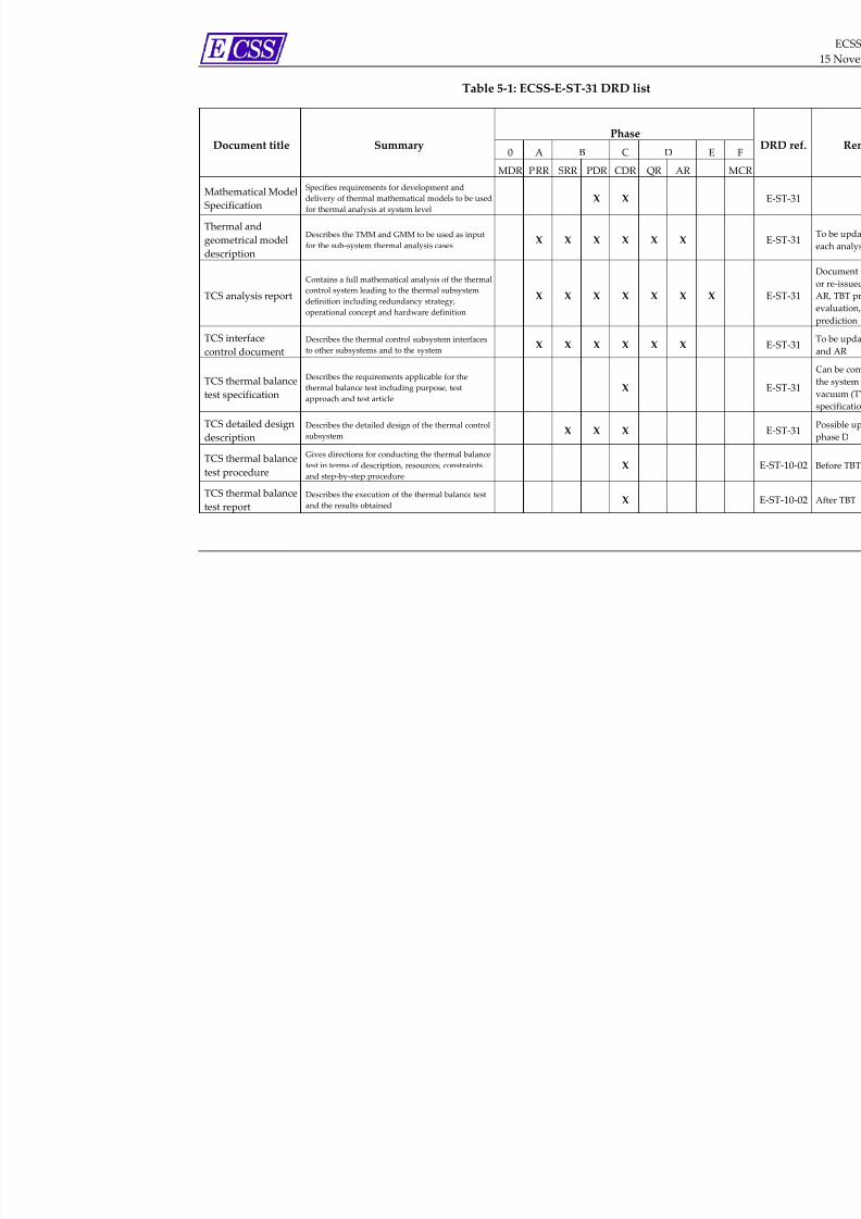
7/22/2019 Ecss e St 31c(15november2008)
http://slidepdf.com/reader/full/ecss-e-st-31c15november2008 42/65
Table 5‐1: ECSS‐E‐ST‐31 DRD list
Phase
0 A B C D E Document
title
Summary
MDR PRR SRR PDR CDR QR AR M
Mathematical Model
Specification
Specifies requirements for development and
delivery of thermal mathematical models to be used
for thermal analysis at system level
X X
Thermal and
geometrical model
description
Describes the TMM and GMM to be used as input
for the sub‐system thermal analysis cases X X X X X X
TCS analysis
report
Contains a full mathematical analysis of the thermal
control system leading to the thermal subsystem
definition including redundancy strategy, operational concept and hardware definition
X
X
X
X
X
X
X
TCS interface
control document
Describes the thermal control subsystem interfaces
to other subsystems and to the system X X X X X X
TCS thermal balance
test specification
Describes the requirements applicable for the
thermal balance test including purpose, test
approach and test article
X
TCS detailed design
description
Describes the detailed design of the thermal control
subsystem X X X
TCS thermal balance
test procedure
Gives directions for conducting the thermal balance
test in terms of description, resources, constraints
and step‐ by‐step procedure
X
TCS thermal balance
test report
Describes the execution of the thermal balance test
and the results obtained X

7/22/2019 Ecss e St 31c(15november2008)
http://slidepdf.com/reader/full/ecss-e-st-31c15november2008 43/65
Phase
0 A B C D E Document title Summary
MDR PRR SRR PDR CDR QR AR M
TCS declared
materials list
Establishes the detailed record of all the materials
used to produce the products of the thermal control
subsystem
X X X X
TCS declared
mechanical parts list
Establishes the detailed record of all the mechanical
parts used to produce the products of the thermal
control subsystem
X X X X
TCS declared
process list
Establishes the detailed record of all the processes
used to produce the products of the thermal control
subsystem
X X X X

7/22/2019 Ecss e St 31c(15november2008)
http://slidepdf.com/reader/full/ecss-e-st-31c15november2008 44/65
ECSS‐E‐ST‐31C
15 November 2008
Annex A (normative)TCS mathematical model specification -
DRD
A.1 DRD identification
A.1.1 Requirement ident if ication and source document
This DRD is called from ECSS‐E‐ST‐31, requirement 4.5.2.1d.
A.1.2 Purpose and objec tive
The TCS mathematical model specification specifies requirements for
development and delivery of mathematical models to be used for thermal
analysis.
A.2 Expected response
A.2.1 Scope and content
<1> Introduction
a. The TCS mathematical model specification shall contain a description of
the purpose, objective, content and the reason prompting its preparation.
NOTE For example:
• This document specifies the requirements
for the delivery of subassembly
mathematical models to the system
authority to be used for system analysis.
• This document specifies requirements for
reduced thermal mathematical models to be
delivered by sub‐contractors and unit
suppliers. The models are introduced in the
global mathematical model of the spacecraft
in order to calculate satellite thermal
performance at system level.
44
7/22/2019 Ecss e St 31c(15november2008)
http://slidepdf.com/reader/full/ecss-e-st-31c15november2008 45/65
ECSS‐E‐ST‐31C
15 November 2008
b. Any open issue, assumption and constraint relevant to this document
shall be stated and described.
<2> Applicable and reference documents
a. The
TCS
mathematical
model
specification
shall list
the
applicable
and
reference documents in support to the generation of the document.
<3> Definitions and abbreviations
a. The TCS mathematical model specification shall list the applicable
directory or glossary and the meaning of specific terms or abbreviations
utilized in this document.
<4> Definition of subassemblies, interfaces and nodal
breakdown
a. The TCS mathematical model specification shall specify the
subassemblies, for which mathematical models are required.
b. The TCS mathematical model specification shall define conductive,
convective and radiative interface nodes and their characteristics.
<5> Node number and node identification
a. The maximum number of nodes for a subassembly model shall be given.
b. A method of identification and numbering of nodes shall be presented.
NOTE For example: Each node is identified by 5 digits
with the following meaning:
• X indicates the type of hardware, i.e. 1 for
MLI, 2 for primary structure, 3 for
secondary structure, etc.
• Y indicates the subassembly or the external
element, to which the node belongs;
• ZZZ indicates the sequence of nodes in the
mathematical model.
<6> Modelling rules
a. The model hierarchy shall be described.
NOTE For example: Level 1 satellite, level 2
subsystem, level 3 assembly, level 4 units
b. The document shall describe the applied modelling rules for thermal
items
NOTE For example: Dissipative items (e.g. number of
nodes), MLI, thermal protection, fluid piping,
and heat pipes.
c. Control algorithms for thermal components shall be described.
45

7/22/2019 Ecss e St 31c(15november2008)
http://slidepdf.com/reader/full/ecss-e-st-31c15november2008 46/65
ECSS‐E‐ST‐31C
15 November 2008
NOTE 1 For example, delivery of thermal data necessary to
simulate the deported items in the System TMM.
NOTE 2 Example of such thermal components are
thermostats, heater, pumps, and coolers.
<7> Software tools
a. The software tools to be used for development of the mathematical
models shall be described.
NOTE 1 The software to be used for the preparation and
delivery of GMMʹs should be ESARAD or
THERMICA.
NOTE 2 The software to be used for the preparation and
delivery of TMMʹs should be ESATAN.
<8> Test cases
a. The thermal mathematical model shall be delivered together with the
definition and results of representative test cases.
A.2.2 Special remarks
None.
46
7/22/2019 Ecss e St 31c(15november2008)
http://slidepdf.com/reader/full/ecss-e-st-31c15november2008 47/65
ECSS‐E‐ST‐31C
15 November 2008
Annex B (normative)Thermal and geometrical model
description - DRD
B.1 DRD identification
B.1.1 Requirement identification and source document
This DRD is called from ECSS‐E‐ST‐31, requirement 4.5.2.1e.
B.1.2 Purpose and objective
The objective of this document is to describe the thermal mathematical models
(GMM and TMM) used for thermal analysis.
B.2 Expected response
B.2.1 Scope and content
<1> Introduction
a. The thermal and geometrical model description shall contain a
description of the purpose, objective, content and the reason prompting
its preparation.
b. Any open issue, assumption and constraint relevant to this document
shall be stated and described.
c. Status and limitations of the models shall be described in detail.
<2> Applicable and reference documents
a. The thermal and geometrical model description shall list the applicable
and reference documents in support to the generation of the document.
<3> Definitions and abbreviations
a. The thermal and geometrical model description shall list the applicable
directory or glossary and the meaning of specific terms or abbreviations
utilized in this document.
47

7/22/2019 Ecss e St 31c(15november2008)
http://slidepdf.com/reader/full/ecss-e-st-31c15november2008 48/65
ECSS‐E‐ST‐31C
15 November 2008
<4> Geometrical mathematical model
a. The document shall describe geometrical models used for thermal
analysis (including identification of surfaces, external geometry, model
lay out).
b. The document shall describe input data and modelling assumptions for view‐factor and external flux calculation.
NOTE For example: Environment, geometry
description, thermo‐optical properties,
insulated and non‐insulated areas, moving
bodies.
c. The document shall describe input data referenced to a coordinate
system as agreed in relevant system ICDs.
d. Heat input shall be presented separately for
1. Solar radiation
2. Planet albedo radiation
3. Planet infrared emission.
e. Geometrical interfaces between spacecraft and appendices or bodies used
in the radiative calculation and not directly related to the spacecraft shall
be described.
NOTE For example: COLUMBUS Module and ISS,
spacecraft and solar array, spacecraft and test
facility.
f. Tools (including version) and computer environment used for establishing geometrical models shall be described.
<5> Thermal mathematical model
a. A complete set of input data for a thermal mathematical model
(including additional heat fluxes not derived by the GMM) shall be
described including all passive and active thermal control features.
b. The Modelling characteristics of active components and interfaces of sub‐
models to the main spacecraft model shall be described.
NOTE
For
example:
Mechanical
pump,
two‐phase
loops, varying conductance devices, heater
control
c. The model description shall contain in detail
1. Model breakdown structure
2. Node numbering hierarchy
3. Node properties
NOTE E.g. heat capacity, area, and dissipation
4. Conductive, radiative and convective couplings
5. Graphical representation of the model
48
7/22/2019 Ecss e St 31c(15november2008)
http://slidepdf.com/reader/full/ecss-e-st-31c15november2008 49/65
ECSS‐E‐ST‐31C
15 November 2008
d. In case model reduction techniques are being applied, these techniques
shall be described and the validity of the reduced model justified.
e. Tools (including version) and computer environment used for
establishing thermal models shall be described.
f. Modelling
constraints
and
critical
implementation
issues
shall
be
described and their relevance on analysis shall be indicated.
<6> Model checks
a. Results of performed checks of TMM and GMM shall be presented.
<7> Files and lists
a. The following information, in a format as agreed with the system
authority, shall be attached to the document as annexes:
1. Identification of delivered computer files,
2. GMM and TMM source lists based on applied tools.
<8> Documentation
a. Model descriptions for GMM and TMM shall be delivered, which
contain:
1. General description of the models
2. Diagrams allowing better understanding of the models
NOTE For example, external geometry and views of the model layout.
3. Test case description
4. Number of rays used for radiative coupling calculation
5. Average and maximum accuracy obtained by the radiative
coupling calculation
6. Number of rays used for external fluxes calculation
7. Number of orbital positions for external fluxes calculation
8.
Relaxation
factor
for
TMM
9. Time step used in the transients
10. Listings containing all the models data (model input files)
11. Test calculation results
12. Convergence criteria for TMM calculation.
b. Models data and test calculation results shall be delivered as electronic
file.
B.2.2 Special remarksNone.
49

7/22/2019 Ecss e St 31c(15november2008)
http://slidepdf.com/reader/full/ecss-e-st-31c15november2008 50/65
ECSS‐E‐ST‐31C
15 November 2008
Annex C (normative)TCS analysis report - DRD
C.1 DRD identification
C.1.1 Requirement identification and source document
This DRD is called from ECSS‐E‐ST‐31, requirement 4.5.2.1f and 4.5.3.1f.
C.1.2 Purpose and objective
The TCS analysis report is produced by the thermal control subsystem supplier
to gather and document the results of analysis. The first issue is produced for
the Phase A and updated throughout the project as further thermal control
subsystem analysis and testing is carried out. The present DRD is also used to
present test prediction and correlation with respect to major subsystem tests,
such as Thermal Balance Test as well as for thermal control system flight
prediction.
The results of all analysis including test prediction and correlation carried out at
subsystem level are reported in TCS analysis report. The documents are
therefore critical for tracking the development of the thermal control subsystem
throughout the project, ensuring that the TCS continues to meet the functional
and performance requirements as the design and implementation are
elaborated.
C.2 Expected response
C.2.1 Scope and content
<1> Introduction
a. The TCS analysis report shall contain a description of the purpose,
objective, content, assumption and constraint and the reason prompting
its preparation.
b. Any open issue relevant to the TCS analysis report shall be stated and
described..
50
7/22/2019 Ecss e St 31c(15november2008)
http://slidepdf.com/reader/full/ecss-e-st-31c15november2008 51/65
ECSS‐E‐ST‐31C
15 November 2008
<2> Applicable and reference documents
a. The TCS analysis report shall list the applicable and reference documents
in support to the generation of the document.
<3> Definitions and
abbreviations
a. The TCS analysis report shall list the applicable directory or glossary and
the meaning of specific terms or abbreviations utilized in this document.
<4> Subsystem status
a. Each issue of the TCS analysis report shall define the underlying design
status of the TCS (development‐ , test‐ , qualification‐ , protoflight‐ , flight‐
model).
b. Each issue of the TCS analysis report shall identify / evaluate analysis
constraints with respect to in‐orbit configuration.
<5> Requirements review
a. The report shall contain a list of subsystem requirements to be met by
analysis.
<6> Overview of analysis approach
a. The TCS analysis report shall provide an overview of the analysis
approach applied to the TCS.
b. The TCS analysis report shall describe the different analysis techniques
used.
c. The TCS analysis report shall include a description of tools used to carry
out the analysis.
d. The TCS analysis report shall refer to GMM and TMM used for each
analysis case.
<7> Description of thermal analysis cases
a. The description shall include a list of assumptions made concerning the
thermal control subsystem and its environment during the analysis.
b. The description shall include a list of all input data including starting
conditions for the analysis cases.
c. The description shall include a justification of assumed uncertainties.
<8> Results of analysis
a. The TCS analysis report shall include the results of the analyses
represented as diagrams, temperature mapping, detailed comparison to
requirements, heat balance.
b. The TCS analysis report shall include a compliance matrix for applicable
requirements.
51

7/22/2019 Ecss e St 31c(15november2008)
http://slidepdf.com/reader/full/ecss-e-st-31c15november2008 52/65
ECSS‐E‐ST‐31C
15 November 2008
c. The results of the analysis shall be presented as electronic file as agreed
with the system authority.
<9> Assessment and conclusions
a. The
TCS
analysis
report
shall
summarize
the
analysis
results
and
the
comparison with the requirements.
b. The TCS analysis report shall provide an overall assessment.
c. The requirement closeout may be summarized in dedicated tables to be
prepared for each involved requirement or a group of requirements.
NOTE For examples see ECSS‐E‐HB‐10‐02.
d. Any open issue shall be clearly stated and described.
e. Based on analysis results recommendations for design changes and
adaptations at subsystem and system level shall be formulated.
C.2.2 Special remarks
None.
52
7/22/2019 Ecss e St 31c(15november2008)
http://slidepdf.com/reader/full/ecss-e-st-31c15november2008 53/65
ECSS‐E‐ST‐31C
15 November 2008
Annex D (normative)TCS interface control document - DRD
D.1 DRD identification
D.1.1 Requirement identification and source document
This DRD is called from ECSS‐E‐ST‐31, requirement 4.3.1b.
D.1.2 Purpose and objective
The TCS interface control document specifies interfaces of thermal control
hardware to other subsystems and to the system. It contains mechanical,
electrical, operational, handling, accommodation and safety requirements and
constraints.
The first draft version of the TCS interface control document is produced for the
PDR and updated issues follow for major project reviews (CDR, FAR). Tailored
TCS interface control document versions are derived for spacecraft development and test models.
The content of this document can be merged with the TCS design description of
Annex F.
D.2 Expected response
D.2.1 Scope and content
<1> Introduction
a. The TCS interface control document shall contain a description of the
purpose, objective, content and the reason prompting its preparation.
b. Any open issue, assumption and constraint relevant to this document
shall be stated and described.
<2> Applicable and reference documents
a. The TCS interface control document shall list the applicable and reference
documents in support to the generation of the document (in particular
thermal item ICDs at lower level).
53
7/22/2019 Ecss e St 31c(15november2008)
http://slidepdf.com/reader/full/ecss-e-st-31c15november2008 54/65
ECSS‐E‐ST‐31C
15 November 2008
<3> Definitions and abbreviations
a. The TCS interface control document shall list the applicable directory or
glossary and the meaning of specific terms or abbreviations utilized in
this document.
<4> Presentation of interface control requirements
a. TCS interfaces shall be defined in an interface control document (ICD),
which includes interface control drawings.
<5> Interface control drawings
a. Reference shall be given to subsystem specific ICDs to be delivered as
separate package.
b. The thermal interface control drawing shall contain:
1. location of thermal hardware within the spacecraft,
2. identification of thermally relevant surface properties,
3. identification of insulated areas including insulation fasteners,
4. location of heaters, thermostats, sensors (test, flight configuration),
5. thermally dictated mounting provisions (identification of interface
filler, number of mounting bolts and torque, MLI mounting
provisions),
6. location of temperature reference points,
7. definition of specific interfaces of thermal fluidic systems,
8. mechanical, electrical, handling and accommodation requirements
as far as presentable in drawings,
9. critical interfaces to other subsystems, to the system and the
launcher.
<6> Thermal interfaces
a. The TCS interface control document shall list thermal interface data,
including:
1. temperature ranges, gradients and variations for mission phases;
2. environmental loads (external fluxes and environmental
temperatures);
3. boundary temperatures and heat fluxes;
4. thermal interface conductance.
<7> Mechanical interfaces
a. The TCS interface control document shall list mechanical interface data
including:
54
7/22/2019 Ecss e St 31c(15november2008)
http://slidepdf.com/reader/full/ecss-e-st-31c15november2008 55/65
ECSS‐E‐ST‐31C
15 November 2008
1. Dimensions, mass, material and surface properties of thermal
hardware
2. Quality of thermally relevant surfaces
NOTE For example: Roughness, flatness.
3. Properties of thermally relevant components, which are under the
responsibility of other subsystems
NOTE For example: Brackets, face sheets of sandwich.
4. Subsystem mass budget.
<8> Electrical interfaces
a. The TCS interface control document shall list the following electrical
interface data:
1. Power consumption of thermal components and electrical
subsystem budget
2. Interfaces of thermal control electrical units
NOTE For example: Redundancy, voltage, resistance,
feed wire characteristic of heaters, pumps,
temperature sensor and Peltier elements.
3. Layout schematics for thermal control electrical circuitry.
NOTE For example: Heater circuits, switches, feedback
control, sensors.
<9> Data handling and monitoring interfaces
a. The TCS interface control document shall identify TM / TC interfaces and
provide a list of on‐ board and ground control parameters.
NOTE For example: Temperature range, precision,
resolution, regulation thresholds, alarm
settings.
<10> Operation, handling, maintenance and safety
a. The TCS
interface
control
document
shall
identify
the
following
thermal
hardware constraints with respect to operation, handling and
maintenance:
1. Operational constraints of thermal control components.
NOTE For example: Heat pipe unit and heat pipe
system operation at different temperatures and
tilt, minimum start‐up power of two‐phase
loops, dry‐run capabilities of mechanical
pumps.
2. Accommodation constraints of thermal control hardware.
NOTE For example: MLI maximum mounting / de‐
mounting cycles.
55

7/22/2019 Ecss e St 31c(15november2008)
http://slidepdf.com/reader/full/ecss-e-st-31c15november2008 56/65
ECSS‐E‐ST‐31C
15 November 2008
3. Requirements to prevent contamination of sensitive thermal
surfaces.
NOTE For example: Cover on thermal radiators
during ground handling and storage.
4. Environmental
requirements
during
transportation
and
at
the
launch site.
5. Precautions and safety requirements for thermal pressurized
components.
D.2.2 Special remarks
None.
56

7/22/2019 Ecss e St 31c(15november2008)
http://slidepdf.com/reader/full/ecss-e-st-31c15november2008 57/65
ECSS‐E‐ST‐31C
15 November 2008
Annex E (normative)TCS thermal balance test specification -
DRD
E.1 DRD identification
E.1.1 Requirement identification and source document
This DRD is called from ECSS‐E‐ST‐31, requirement 4.5.3.1a.
E.1.2 Purpose and objective
The TCS thermal balance test specification describes in detail the test
requirements applicable to the thermal control subsystem thermal balance test.
In particular it defines the purpose of the test, the test approach, the test article
and the set‐up, the required GSE, test equipment and instrumentation, test
conditions,
test
sequences,
test
facility,
pass
/
fail
criteria,
required
documentation, participants and test schedule.
The TCS thermal balance test specification is used as an input to the test
procedures, as a requirement document for booking the environmental test
facility and to provide to the customer details of the test activity in advance of
the activity itself.
The test specification is used as basis for writing the relevant test procedures
and test report, which is generally performed by personnel of the test facility.
In writing the test specification potential overlaps with the test procedure are
minimized (i.e. the test specification gives emphasis on requirements, the test
procedure on operative step‐ by‐step instructions).
E.2 Expected response
E.2.1 Scope and content
<1> Introduction
a. The TCS thermal balance test specification shall contain a description of
the purpose, objective, content and the reason prompting its preparation.
57
7/22/2019 Ecss e St 31c(15november2008)
http://slidepdf.com/reader/full/ecss-e-st-31c15november2008 58/65
ECSS‐E‐ST‐31C
15 November 2008
b. Any open issue, assumption and constraint relevant to this document
shall be stated and described.
<2> Applicable and reference documents
a. The
TCS
thermal balance
test
specification
shall
list
the
applicable
and
reference documents in support to the generation of the document.
<3> Definitions and abbreviations
a. The TCS thermal balance test specification shall list the applicable
directory or glossary and the meaning of specific terms or abbreviations
utilized in this document.
<4> Requirements to be verified
a. The TCS
thermal
balance
test
specification
shall
list
the
requirements
to
be verified in the TBT and shall provide traceability where in the test the
requirement is covered.
<5> Test approach
a. The TCS thermal balance test specification shall summarize the test
objectives of and the approach to the test activity.
NOTE 1 Test objective is the verification of the thermal
mathematical model of the subsystem by
comparing test results with test predictions in
order to verify with the correlated model the
thermal control subsystem design.
NOTE 2 The discussion of the selection of test cases, the
suitability of a reduced spacecraft hardware model
(due to test facility constraints), non‐flight
condition of fluidic systems, applicability of solar
simulation, the necessity of a rotating spacecraft,
etc. are elements to explain the test approach.
<6> Test definition
a. The TCS thermal balance test specification shall define the configuration
of the test article, including number, type, location of sensors, acquisition
rate and format output, the test set‐up, the necessary GSE, the test
conditions and the applicable constraints.
NOTE The TBT should be harmonized with the system
thermal vacuum test (TVT), which generally
takes place in sequential order in the same
vacuum chamber.
58

7/22/2019 Ecss e St 31c(15november2008)
http://slidepdf.com/reader/full/ecss-e-st-31c15november2008 59/65
ECSS‐E‐ST‐31C
15 November 2008
<7> Test facility
a. The TCS thermal balance test specification shall list the applicable test
facility requirements together with the instrumentation, data acquisition
and test equipment to be used.
NOTE Test facility requirements are defined in close
cooperation with the TVT authority.
<8> Test sequence
a. The TCS thermal balance test specification shall list the test activity flow
and the associated requirements.
<9> Pass/fail criteria
a. The TCS thermal balance test specification shall list the pass/fail criteria.
NOTE Pass/fail criteria are related to the flawless
operation of thermal hardware.
<10> Test documentation
a. The TCS thermal balance test specification shall list the requirements for
the involved documentation (including test procedure, test report and
PA / QA records).
NOTE Requirements for test procedure and test report
should constitute a clear baseline for
establishing these
documents
by
the
test
facility
authority.
<11> Test organization
a. The TCS thermal balance test specification shall list the test
responsibilities, participants to be involved and the schedule outline.
E.2.2 Special remarks
None.
59

7/22/2019 Ecss e St 31c(15november2008)
http://slidepdf.com/reader/full/ecss-e-st-31c15november2008 60/65
ECSS‐E‐ST‐31C
15 November 2008
Annex F (normative)TCS detailed design description - DRD
F.1 DRD identif ication
F.1.1 Requirement identification and source document
This DRD is called from ECSS‐E‐ST‐31, requirement 4.4.1c.
F.1.2 Purpose and objective
The TCS detailed design description provides a comprehensive technical
description of the thermal control subsystem including justification that the
design meets the performance requirements specified in the subsystem
specification.
The thermal control subsystem supplier produces the TCS detailed design
description for the system CDR and its acceptance at the CDR implies a
commitment by the system authority to proceed with the implementation of the
subsystem according to that detailed design.
F.2 Expected response
F.2.1 Scope and content
<1> Introduction
a. The TCS detailed design description shall contain a description of the
purpose, objective, content and the reason prompting its preparation.
b. Any open issue, assumption and constraint relevant to this document
shall be stated and described.
<2> Applicable and reference documents
a. The TCS detailed design description shall list the applicable and
reference documents in support to the generation of the document.
60

7/22/2019 Ecss e St 31c(15november2008)
http://slidepdf.com/reader/full/ecss-e-st-31c15november2008 61/65
ECSS‐E‐ST‐31C
15 November 2008
<3> Definitions and abbreviations
a. The TCS detailed design description shall list the applicable directory or
glossary and the meaning of specific terms or abbreviations utilized in
this document.
<4> Summary of design requirements
a. The TCS detailed design description shall summarize the driving design
requirements (reference to other documents for details) for the
subsystem, including:
1. Mission requirements
2. Definition of orbits, which are relevant for the subsystem design
(i.e. orbits for warm and cold design cases)
3. Timeline and load cases
4. Spacecraft geometry and coordinate system
5. Temperature limit, temperature gradients and temperature
stability requirements
6. Properties of spacecraft equipment (i.e. thermal, mechanical, heat
dissipation).
<5> Thermal control design concept, functional description
and justification
a. The TCS detailed design description shall describe and justify the
selected subsystem design concept.
NOTE This clause defines the thermal control concept
based on functional requirements. It justifies
the selection of passive or active thermal
control, the use of single‐phase or two‐phase
cooling loops, location of insulation and
thermal radiators, selection of heater and its
control, selection and location of thermally
active surfaces, etc.
<6> Detailed design
description
a. The TCS detailed design description shall provide a detailed design
description of all thermal hardware, including:
1. Thermal hardware definition and implementation constraints
2. Control logic of active components
3. Definition of material properties, processes and specific
mechanical parts
NOTE As far as possible reference should be made to
the subsystem DML, DMPL and DPL in order
to avoid duplication of information.
4. Temperature monitoring and control.
61

7/22/2019 Ecss e St 31c(15november2008)
http://slidepdf.com/reader/full/ecss-e-st-31c15november2008 62/65
ECSS‐E‐ST‐31C
15 November 2008
<7> Reliability and redundancy concept
a. The TCS detailed design description shall present the verification that the
subsystem meets the specified reliability requirement including used
redundancy concepts,
<8> Thermal control subsystem operations
a. The TCS detailed design description shall identify and describe any
required operations of the subsystem in particular for the following
mission phases:
1. System start up at beginning of mission
2. Nominal mode
3. Survival mode
4. Thermal transition and recovery modes.
b. The TCS detailed design description shall define and describe any
operational measures for failure detection and correction.
<9> Thermal control subsystem budgets
a. The TCS detailed design description shall list the subsystem budgets for
mass, electrical power and telecommand / telemetry.
<10> ICDs of major components
a. The TCS
detailed
design
description
shall
include
the
ICDs
of
the
major
thermal control subsystem components.
NOTE As far as possible reference is made to the
subsystem ICD (see Annex D) in order to avoid
duplication of information.
F.2.2 Special remarks
None.
62

7/22/2019 Ecss e St 31c(15november2008)
http://slidepdf.com/reader/full/ecss-e-st-31c15november2008 63/65
ECSS‐E‐ST‐31C
15 November 2008
Annex G (informative)Cryogenic temperature range
In this informative annex references to specific definitions and requirements,
which are applicable to the cryogenic temperature range and listed in the body
text of the Standard, are summarized in Table G‐1.
This summary facilitates the overview of definitions and requirements for this
temperature range.
NOTE Unless otherwise defined, all requirements in
this Standard are applicable to the cryogenic
temperature range.
Table G‐1: Definitions and requirements for the cryogenic
temperature range used in this Standard
Clause reference Domain of definition or requirement
3.2.3 Definitions for cryogenic temperature range
4.2.3 Requirements for
cryogenic
temperature
range
4.5.2.2 Verification requirements for CCS
63

7/22/2019 Ecss e St 31c(15november2008)
http://slidepdf.com/reader/full/ecss-e-st-31c15november2008 64/65
ECSS‐E‐ST‐31C
15 November 2008
Annex H (informative)High temperature range
In this informative annex references to specific definitions and requirements,
which are applicable to the high temperature range and listed in the body text
of the Standard, are summarized in Table H‐1.
This summary facilitates the overview of definitions and requirements for this
temperature range.
NOTE Unless otherwise defined, all requirements in
this Standard are applicable to the high
temperature range.
Table H‐1: Definitions and requirements for the high temperature
range used in this Standard
Clause reference Domain of definition or requirement
3.2.4 Definitions for high temperature range
3.2.4.14 Definition of
thermal
protection
subsystem
(TPS)
4.2.2 Requirements for high temperature range
4.5.2.3 Verification requirements for TPS
64

7/22/2019 Ecss e St 31c(15november2008)
http://slidepdf.com/reader/full/ecss-e-st-31c15november2008 65/65
ECSS‐E‐ST‐31C
15 November 2008
Bibliography
ECSS‐S‐ST‐00 ECSS system – Description, implementation and
general requirements