econoplate bv series hot water service … · 1 . econoplate bv series hot water service . packaged...
TRANSCRIPT

1
ECONOPLATE BV SERIES HOT WATER SERVICE
PACKAGED HEAT EXCHANGERS WITH THERMAL STORES
TECHNICAL AND INSTALLATION
DOCUMENTATION
STOKVIS ENERGY SYSTEMS UNIT 34 CENTRAL PARK ESTATE 34 CENTRAL PARK ESTATE WEST MOLESEY SURREY. KT8 2QZ TEL: 0208 783 3050 FAX: 0208 783 3051 E-MAIL:[email protected]
WEBSITE:www.stokvisboilers.com
ECONOPLATE BV21112017 DOC188 V8

2
3
STOKVIS ECONOPLATE BV SERIES
GENERAL DESCRIPTION
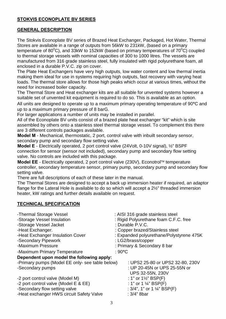
The Stokvis Econoplate BV series of Brazed Heat Exchanger, Packaged, Hot Water, Thermal Stores are available in a range of outputs from 56kW to 231kW, (based on a primary temperature of 800C), and 33kW to 152kW (based on primary temperatures of 700C) coupled to thermal storage vessels with nominal capacities of 300 to 1000 litres. The vessels are manufactured from 316 grade stainless steel, fully insulated with rigid polyurethane foam, all enclosed in a durable P.V.C. zip on cover. The Plate Heat Exchangers have very high outputs, low water content and low thermal inertia making them ideal for use in systems requiring high outputs, fast recovery with varying heat loads. The thermal store allows for those high peaks which occur at various times, without the need for increased boiler capacity. The Thermal Store and Heat exchanger kits are all suitable for unvented systems however a suitable set of unvented kit equipment is required to do so. This is available as an option. All units are designed to operate up to a maximum primary operating temperature of 90°C and up to a maximum primary pressure of 8 barG. For larger applications a number of units may be installed in parallel.
All of the Econoplate BV units consist of a brazed plate heat exchanger “kit” which is site assembled by others onto a stainless steel thermal storage vessel. To complement this there are 3 different controls packages available. Model M - Mechanical, thermostatic, 2 port, control valve with inbuilt secondary sensor, secondary pump and secondary flow setting valve. Model E - Electrically operated, 2 port control valve (24Volt, 0-10V signal), ½” BSPF connection for sensor (sensor not included), secondary pump and secondary flow setting valve. No controls are included with this package. Model EE - Electrically operated, 2 port control valve (230V), Econotrol temperature controller, secondary temperature sensor, primary pump, secondary pump and secondary flow setting valve. There are full descriptions of each of these later in the manual. The Thermal Stores are designed to accept a back up immersion heater if required, an adaptor flange for the Lateral Hole is available to do so which will accept a 2½” threaded immersion heater, kW ratings and further details available on request.
TECHNICAL SPECIFICATION
-Thermal Storage Vessel : AISI 316 grade stainless steel -Storage Vessel Insulation : Rigid Polyurethane foam C.F.C. free -Storage Vessel Jacket : Durable P.V.C. -Heat Exchanger. : Copper brazed/Stainless steel -Heat Exchanger Insulation Cover : Expanded polyurethane/Polystyrene 475K -Secondary Pipework : LG2/brass/copper -Maximum Pressure : Primary & Secondary 8 bar -Maximum Primary Temperature : 90°C Dependent upon model the following apply: -Primary pumps (Model EE only- see table below) : UPS2 25-80 or UPS2 32-80, 230V -Secondary pumps : UP 20-45N or UPS 25-55N or UPS 32-55N, 230V -2 port control valve (Model M) : 1” or 1½” BSP(F) -2 port control valve (Model E & EE) : 1” or 1 ¼” BSP(F) -Secondary flow setting valve : 3/4”, 1” or 1 ¼” BSP(F) -Heat exchanger HWS circuit Safety Valve : 3/4” 8bar

4
Thermal Storage Vessel Dimensions
(Excluding heat exchanger kit)
-300 litre vessel : 287 l volume,1685 mm high, 620 mm diameter. -500 litre vessel : 480 l volume,1690 mm high, 770 mm diameter. -800 litre vessel : 792 l volume,1840 mm high, 950 mm diameter. -1000litre vessel: 990 l volume, 2250 mm high, 950 mm diameter. Add 230mm for the heat exchanger kit for Models M & E and 280mm for Model EE. A clearance of at least 250mm should be allowed around the assembled unit for access and maintenance. If an immersion heater is the be fitted then the clearance in front of the Thermal Store Control Panel and Lateral Hole should be increased to match the diameter of the vessel.
Thermal Storage Vessel Connections
-Cold water feed: 300/500/800/1000litre : 2”BSP(M) -Hot water service flow: 300/500/800/1000litre : 2”BSP(M) -Hot water service return: 300/500/800/1000litre : 11/2”BSP(M) -Vessel drain connection 300/500litre : 1” BSP(M) -Vessel drain connection 800/1000litre : 11/4” BSP(M) -For all other vessel connections please refer to the drawing included later in this document N.B. Models M & E are not supplied with a primary pump, correct selection of this pump is important to ensure the duty is achieved. In addition, if a fixed flow pump is used (as opposed to a variable speed) an additional bypass or differential control valve will be required. See below for primary flow rate and pressure drop figures.
ECONOPLATE BV MODEL M
VALVE SIZE( INLET)
PRIMARY FLOW RATE l/s
PRIMARY OUTLET
PRIMARY PRESSURE DROP (kPa)
BV10/10 25mm 0.56 25mm 77 BV10/20 25mm 1.02 25mm 81 BV10/30 25mm 1.22 25mm 79 BV10/40 40mm 1.40 25mm 59 BV10/50 40mm 1.49 25mm 57
ECONOPLATE BV MODEL E
VALVE SIZE (INLET)
PRIMARY FLOW RATE l/s
PRIMARY OUTLET
PRIMARY PRESSURE DROP (kPa)
BV10/10 25mm 0.56 25mm 72 BV10/20 25mm 1.02 25mm 63 BV10/30 25mm 1.22 25mm 53 BV10/40 32mm 1.40 25mm 40 BV10/50 32mm 1.49 25mm 37
ECONOPLATE BV MODEL EE
VALVE SIZE(OUTLET)
PRIMARY FLOW RATE l/s
PRIMARY PUMP MODEL
(INLET)
PRIMARY PRESSURE DROP (kPa)
BV10/10 25mm 0.56 UPS2 25-80 72 BV10/20 25mm 1.02 UPS2 25-80 63 BV10/30 25mm 1.22 UPS2 25-80 53 BV10/40 32mm 1.40 UPS2 32-80 40 BV10/50 32mm 1.49 UPS2 32-80 37

5
CONTROLS PACKAGES
All standard thermal stores as listed earlier come with a control panel incorporating an ON/OFF switch and green “Power” lamp, enable thermostat and manual reset high limit thermostat, amber “Ready” lamp and temperature gauge. Model M : Mechanical, thermostatic, 2 port, control valve with in-built secondary sensor, secondary pump, secondary flow setting valve, and all secondary pipework required to install the kit on to the thermal store. The secondary circuit pipework includes isolating valves and unions for easy connection to the thermal store. The primary pump/primary flow is to be supplied by the customer from the heat source circuit.
Model E : Electrically operated, 2 port control valve (24volt, 0-10v signal), ½” BSPF connection
for sensor (sensor not included), secondary pump, secondary flow setting valve, and all secondary pipework required to install the kit on to the thermal store. The secondary circuit pipework includes isolating valves and unions for easy connection to the thermal store. The primary pump and control system is not included. External temperature controls are required to operate the control valve to regulate the temperatures from the heat exchanger.
Model EE : Electrically operated, 2 port control valve (230V), Econotrol controller, secondary temperature sensor, primary pump, secondary pump, interconnecting wiring, secondary flow setting valve, all secondary pipework required to install the kit on to the thermal store. The secondary circuit pipework includes isolating valves and unions for easy connection to the store. The primary inlet is to be connected to the primary pump and the return to the 2 port valve, both using the unions provided. The primary pump included has a “spare head allowance” of at least 6 kPa for external pipework losses. The Econotrol is an Electronic PID temperature controller with the following features. : 7 day time clock control of 2 temperature settings and/or 1 temperature /night off, per day. : Safety extra low voltage circuit for external “clock” control. : Safety extra low voltage circuit for Thermal Store Enable Thermostat. : Adjustable high limit and low limit temperature alarms, temp. alarm lamp, common volt free temp. alarm and selectable high temp. lockout modes. (low temperature alarm disabled in this application) : Functional indication of: pump enabled, valve opening or closing. : LCD Digital display of day and time, and secondary flow temperature and any faults : Full menu driven interrogation of parameters and operating modes. : 500mA control fuse, 10A output fuse Full Model designations are made up in the following way: BV10/ = Heat exchanger type: Brazed, type 10. …./?? = Size of heat exchanger (number of plates). …./../???? = Nominal capacity of thermal storage vessel in litres. …./../…./? = Model type: Mechanical (M), Electrical (E), Electrical c/w Econotrol(EE) e.g. A 30 plate brazed heat exchanger with mechanical, thermostatic control valve on a 500 litre nominal capacity vessel would be designated e.g. A 50 plate brazed heat exchanger with electrical control valve c/w Econotrol on a 1000 litre nominal capacity vessel would be designated
BV10/30/500/M
B10/50/1000/EE

6
PERFORMANCE GUIDE FOR ECONOPLATE BV RANGE (PRIMARY TEMPERATURE 80OC , COLD FEED 10OC )
ECONOPLATE BV MODELBV10/10/300 BV10/20/300 BV10/30/300 BV10/40/300 BV10/50/300
CONTINUOUS OUTPUT 17.4 35.4 47.4 59.4 66AT 60OC litre/minPEAK OUTPUT 432 612 732 852 918litre/10minPEAK OUTPUT 1302 2382 3102 3822 4218litre/60minPRIMARY FLOW RATE litre/sec 0.56 1.02 1.22 1.40 1.49
HEAT LOAD REQUIRED kW 56 123 166 205 231
APPROX VESSEL RECOVERY TIME 17 Mins 8 Mins 6 Mins 5 Mins 5 Mins(Assuming no hot water draw off)
BV10/10/500 BV10/20/500 BV10/30/500 BV10/40/500 BV10/50/500CONTINUOUS OUTPUT 17.4 35.4 47.4 59.4 66AT 60OC litre/minPEAK OUTPUT 606 786 906 1026 1092litre/10minPEAK OUTPUT 1476 2556 3276 3996 4392litre/60minPRIMARY FLOW RATE litre/sec 0.56 1.02 1.22 1.40 1.49
HEAT LOAD REQUIRED kW 56 123 166 205 231
APPROX VESSEL RECOVERY TIME 28 Mins 14 Mins 10 Mins 8 Mins 8 Mins(Assuming no hot water draw off)
BV10/10/800 BV10/20/800 BV10/30/800 BV10/40/800 BV10/50/800CONTINUOUS OUTPUT 17.4 35.4 47.4 59.4 66AT 60OC litre/minPEAK OUTPUT 887 1067 1187 1307 1373litre/10minPEAK OUTPUT 1757 2837 3557 4277 4673litre/60minPRIMARY FLOW RATE litre/sec 0.56 1.02 1.22 1.40 1.49
HEAT LOAD REQUIRED kW 56 123 166 205 231
APPROX VESSEL RECOVERY TIME 46 Mins 22 Mins 17 Mins 13 Mins 12 Mins(Assuming no hot water draw off)
BV10/10/1000 BV10/20/1000 BV10/30/1000 BV10/40/1000 BV10/50/1000CONTINUOUS OUTPUT 17.4 35.4 47.4 59.4 66AT 60OC litre/minPEAK OUTPUT 1065 1245 1365 1485 1551litre/10minPEAK OUTPUT 1935 3015 3735 4455 4851litre/60minPRIMARY FLOW RATE litre/sec 0.56 1.02 1.22 1.40 1.49
HEAT LOAD REQUIRED kW 56 123 166 205 231
APPROX VESSEL RECOVERY TIME 57 mins 28 Mins 21 Mins 17 Mins 15 Mins(Assuming no hot water draw off)

7
PERFORMANCE GUIDE FOR ECONOPLATE BV RANGE (PRIMARY TEMPERATURE 70OC , COLD FEED 10OC )
ECONOPLATE BV MODELBV10/10/300 BV10/20/300 BV10/30/300 BV10/40/300 BV10/50/300
CONTINUOUS OUTPUT 9.6 22.2 30.6 38.4 43.8AT 60OC litre/minPEAK OUTPUT 354 480 564 642 696litre/10minPEAK OUTPUT 834 1590 2094 2562 2886litre/60minPRIMARY FLOW RATE litre/sec 0.56 1.02 1.22 1.40 1.49
HEAT LOAD REQUIRED kW 33 77 107 133 152
APPROX VESSEL RECOVERY TIME 30 Mins 13 Mins 9 Mins 7 Mins 7 Mins(Assuming no hot water draw off)
BV10/10/500 BV10/20/500 BV10/30/500 BV10/40/500 BV10/50/500CONTINUOUS OUTPUT 9.6 22.2 30.6 38.4 43.8AT 60OC litre/minPEAK OUTPUT 528 654 738 816 870litre/10minPEAK OUTPUT 1008 1764 2268 2736 3060litre/60minPRIMARY FLOW RATE litre/sec 0.56 1.02 1.22 1.40 1.49
HEAT LOAD REQUIRED kW 33 77 107 133 152
APPROX VESSEL RECOVERY TIME 50 Mins 22 Mins 16 Mins 13 Mins 11 Mins(Assuming no hot water draw off)
BV10/10/800 BV10/20/800 BV10/30/800 BV10/40/800 BV10/50/800CONTINUOUS OUTPUT 9.6 22.2 30.6 38.4 43.8AT 60OC litre/minPEAK OUTPUT 809 935 1019 1097 1151litre/10minPEAK OUTPUT 1289 2045 2549 3017 3341litre/60minPRIMARY FLOW RATE litre/sec 0.56 1.02 1.22 1.40 1.49
HEAT LOAD REQUIRED kW 33 77 107 133 152
APPROX VESSEL RECOVERY TIME 83 Mins 36 Mins 26 Mins 21 Mins 18 Mins(Assuming no hot water draw off)
BV10/10/1000 BV10/20/1000 BV10/30/1000 BV10/40/1000 BV10/50/1000CONTINUOUS OUTPUT 9.6 22.2 30.6 38.4 43.8AT 60OC litre/minPEAK OUTPUT 987 1113 1197 1275 1329litre/10minPEAK OUTPUT 1467 2223 2727 3195 3519litre/60minPRIMARY FLOW RATE litre/sec 0.56 1.02 1.22 1.40 1.49
HEAT LOAD REQUIRED kW 33 77 107 133 152
APPROX VESSEL RECOVERY TIME 103 mins 45 Mins 32 Mins 26 Mins 23 Mins(Assuming no hot water draw off)

8
INSTALLATION SCHEMATICS
Typical Schematic of an Econoplate BV, Models M or E with Unvented Cold Feed.
HWS DRAW OFF
EXPANSION VESSEL
COLD WATERSERVICE
DOUBLE NRV& PRESSURE REG. VALVE
T & P VALVEOPTIONS
NRV
SAFETY VALVE
AUTO AIR VALVE
CLIENT SUPPLYPRIMARY
SAFETY VALVE
ECONOPLATE BV& STORAGE VESSEL
HEAT EXCHANGERPACKAGE
Typical Schematic of Econoplate BV Model EE on a Combined Heating & Hot Water System with Unvented Cold Feed.
HWS DRAW OFF
EXPANSION VESSEL
COLD WATERSERVICE
AUTO AIR VALVE
DOUBLE NRV& PRESSURE REG. VALVE
T & P VALVE
NRV
SAFETY VALVE
SAFETY VALVE
BOILER/HEAT SOURCE
ECONOPLATE BV& STORAGE VESSEL
HEATING CIRCUIT
LOW LOSSHEADER
HEAT EXCHANGERPACKAGE

9
THERMAL STORE/VESSEL FULL DIMENSIONAL DATA

10
CONNECTION DETAILS MODELS M & E
K
J
D
H
A
B
C
G G
F
E
Inspection Opening DN100 or
Immersion Htr Boss 65mm female BSP
Inspection Opening & Pocket for Extra Thermometer @ top
BA C
F E
G
D
H
K
J
G
L
A2
MODEL M & E
CONNECTION SCHEDULEA2 = 65mm female T & P VALVE
A = 50mm male HWS
B = 40mm male RECIRC
C = 50mm male CWF
D = 25mm male DRAIN OFF ( 300-500) 32mm male DRAIN OFF ( 800-1000)
E = 50mm male BPHE SEC FLOW
F = 50mm male BPHE SEC RETURN G = 25mm male VENT
H = 15mm male TAPPING
J = 25mm female PRIMARY FLOW (B10/10 - B10/30) 32mm female PRIMARY FLOW (B10/40 - B10/50 MODEL E) 40mm female PRIMARY FLOW (B10/40 - B10/50 MODEL M)
K = 25mm female PRIMARY RETURN
L = 15mm female CLIENT SENSOR or Model M POCKET
M = 25mm SAFETY VALVE DISCHARGE
Vessel Control panel
M

11
CONNECTION DETAILS MODEL EE
K
J
D
H
A
B
C
G G
F
E
Inspection Opening DN100 or
Immersion Htr Boss 65mm female BSP
Inspection Opening & Pocket for Extra Thermometer @ top
BA C
F E
G
D
H
K
J
G
L
A2
Econotrol 2100
A2 = 65mm female T & P VALVE
A = 50mm male HWS
B = 40mm male RECIRC
C = 50mm male CWF
D = 25mm male DRAIN OFF ( 300-500) 32mm male DRAIN OFF ( 800-1000)
E = 50mm male BPHE SEC FLOW
F = 50mm male BPHE SEC RETURN G = 25mm male VENT
H = 15mm male TAPPING
J = 25mm female PRIMARY FLOW (B10/10 - B10/30) 32mm female PRIMARY FLOW (B10/40 - B10/50)
K = 25mm female PRIMARY RETURN B10/10 - B10/30) 32mm female PRIMARY RETURN (B10/40 - B10/50)
L = SENSOR Stud coupling
M = 25mm SAFETY VALVE DISCHARGE
MODEL EE
CONNECTION SCHEDULE
Vessel Control panel
M
12
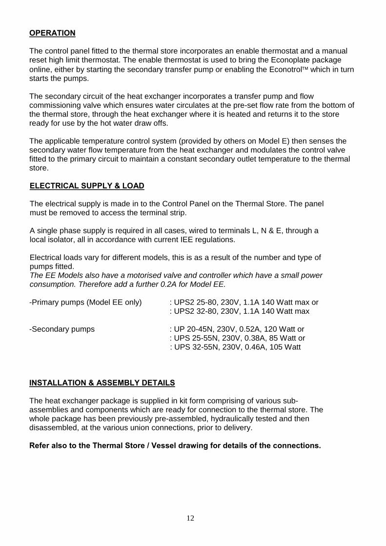
OPERATION
The control panel fitted to the thermal store incorporates an enable thermostat and a manual reset high limit thermostat. The enable thermostat is used to bring the Econoplate package online, either by starting the secondary transfer pump or enabling the Econotrol which in turn starts the pumps. The secondary circuit of the heat exchanger incorporates a transfer pump and flow commissioning valve which ensures water circulates at the pre-set flow rate from the bottom of the thermal store, through the heat exchanger where it is heated and returns it to the store ready for use by the hot water draw offs. The applicable temperature control system (provided by others on Model E) then senses the secondary water flow temperature from the heat exchanger and modulates the control valve fitted to the primary circuit to maintain a constant secondary outlet temperature to the thermal store. ELECTRICAL SUPPLY & LOAD The electrical supply is made in to the Control Panel on the Thermal Store. The panel must be removed to access the terminal strip. A single phase supply is required in all cases, wired to terminals L, N & E, through a local isolator, all in accordance with current IEE regulations. Electrical loads vary for different models, this is as a result of the number and type of pumps fitted. The EE Models also have a motorised valve and controller which have a small power consumption. Therefore add a further 0.2A for Model EE. -Primary pumps (Model EE only) : UPS2 25-80, 230V, 1.1A 140 Watt max or : UPS2 32-80, 230V, 1.1A 140 Watt max -Secondary pumps : UP 20-45N, 230V, 0.52A, 120 Watt or : UPS 25-55N, 230V, 0.38A, 85 Watt or : UPS 32-55N, 230V, 0.46A, 105 Watt
INSTALLATION & ASSEMBLY DETAILS The heat exchanger package is supplied in kit form comprising of various sub-assemblies and components which are ready for connection to the thermal store. The whole package has been previously pre-assembled, hydraulically tested and then disassembled, at the various union connections, prior to delivery. Refer also to the Thermal Store / Vessel drawing for details of the connections.

13
All Models Component 1 : The heat exchanger sub-assembly, which incorporates the heat exchanger secondary flow and heat exchanger safety valve, is fitted to connection E on the thermal store using the union connection provided. The safety valve outlet should be piped to drain via a tundish.
1
E
Component 2 : The secondary return sub-assembly, including transfer pump is fitted to connection F on the thermal store using the union connection provided and is then connected to the bottom union connection of the heat exchanger assembly. When connected check all pipe and fittings for tightness. The secondary section of the assembly is now complete.
1
2
E
F
14
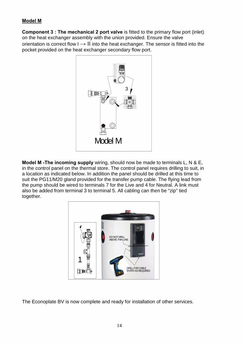
Model M Component 3 : The mechanical 2 port valve is fitted to the primary flow port (inlet) on the heat exchanger assembly with the union provided. Ensure the valve orientation is correct flow I → II into the heat exchanger. The sensor is fitted into the pocket provided on the heat exchanger secondary flow port.
Model M
3
Model M -The incoming supply wiring, should now be made to terminals L, N & E, in the control panel on the thermal store. The control panel requires drilling to suit, in a location as indicated below. In addition the panel should be drilled at this time to suit the PG11/M20 gland provided for the transfer pump cable. The flying lead from the pump should be wired to terminals 7 for the Live and 4 for Neutral. A link must also be added from terminal 3 to terminal 5. All cabling can then be “zip” tied together.
1
DO NOT DRILLABOVE THIS LINE
DRILL FOR CABLE ENTRY AS REQUIRED
The Econoplate BV is now complete and ready for installation of other services.

15
Model M Wiring Details
L NE
B CA
3 4 5 7 86
D
230VSUPPLY
A
B
1
2
3
SWITCH
STORAGE VESSEL PANELPOWER ON
(GREEN)READY
(ORANGE)
LIMIT STAT
ENABLE STAT
10 119
SECONDARY PUMP WITH ALPHA PLUG FLEX LEAD FITTED TO PUMP
P
LINK
Model E Component 3a : The 24V electrical 2 port valve is fitted to the primary flow port (inlet) on the heat exchanger assembly with the union provided. Ensure the valve orientation is correct flow A → AB into the heat exchanger. The drive is supplied with a flexible cable for connection to “customer” temperature control equipment. A ½” BSP connection is provided on the heat exchanger secondary flow port for customer secondary temperature sensor.
Sensor connection
Model E
3a

16
Actuator Wiring Details for the 2 Port Valve on Model E
The direction of response to the 0-10V control signal is reversible. Direction of operation 1 (24V on the brown (BN) cable). When the positioning signal is increased the actuator rod moves out and opens the valve. Direction of operation 2 (24V on the black (BK) cable). When the positioning signal is increased the actuator rod moves in and closed the valve. There are 3 dip switched in the actuator which are used for setting speed and valve characteristics. When set 1= OFF / 2=OFF / 3=ON the actuator will have a speed of 35 seconds and an =% response characteristic. Econoplate BV Thermal Storage Vessel Control Panel. As supplied the wiring of the panel is as shown and could be used in a similar way to the Model M if required
L NE
B CA
3 4 5 7 86
D
230VSUPPLY
A
B
1
2
3
SWITCH
STORAGE VESSEL PANELPOWER ON(GREEN)
READY(ORANGE)
LIMIT STAT
ENABLE STAT
10 119

17
Model EE Component 3a & 4 : The 230V, 2 port valve (3a) is fitted to the primary return port on the heat exchanger assembly with the union provided. Ensure the valve orientation is correct flow A → AB away from the heat exchanger. The primary pump (4) is fitted to the primary inlet port on the heat exchanger with the union provided ensuring the pump shaft is in the horizontal plane. The flow direction on the pump should be into the heat exchanger.
3a
4
Model EE
Component 5 : The Econotrol Controller has a pre-mounting bracket which is used to attach it to the top of the thermal store using 2 x self tapping screws. It is provided with pre-wired flying leads, which should be plugged into both the primary and secondary pumps, a 5 core cable for the power and controls connection cable to the control panel of the thermal store and the prewired secondary temperature sensor. A cable gland has also been fitted to the Econotrol for entry of the flying lead fitted to the 2 port valve.
5
DRILL FOR CABLE ENTRY AS REQUIRED
DO NOT DRILLABOVE THIS LINE

18
The PT100 sensor should now be fitted into the stud coupling located on the secondary flow from the heat exchanger, taking care not to over tighten against the olive.
With the Econotrol now mounted on the thermal store connect the 2 port control valve actuator wiring as detailed below. The incoming supply wiring, should now be made to terminals L, N & E, in the control panel on the thermal store. The control panel requires drilling to suit, in a location as indicated above. In addition the 5 core cable from the Econotrol needs to be wired as below, this is for the supply and enable wiring to the Econotrol. Drill to suit the PG11/M20 gland provided, again in the location indicated above. Model EE Wiring Details
L NE
B CA
3 4 5 7 86
D
230VSUPPLY
L N EN - M +
ALARMP2P1
SECONDARY PUMP
BA
SENSORCLOCK I/LOCKEXTEXT
EE ENN
P
P1
PUMP 1PRIMARY NIGHT
DAYM
ACTUATORTERMINALS
A
B
1
2
3
SWITCH
STORAGE VESSEL PANELPOWER ON
(GREEN)READY
(ORANGE)
10 119
5 CORE CABLE(PREWIRED TO ECONOTROL)
ECONOTROL 2100
BLAC
K
BROW
N
BLUE
BROW
NBL
UE
BROW
N
BLUE
ENABLE STAT
LIMIT STAT
. The Econoplate BV is now complete and ready for installation of other services.

19
COMMISSIONING
The Thermal Store Control Panel incorporates a combined thermostat for the enable (adjustable) and manual reset high limit thermostat (preset to 90°C). The enable thermostat should be adjusted and set to the SWITCH ON temperature for hot water generation. There is a spring clip on the rear of the dial which can be used to restrict the setting of this thermostat if required (see below).
The Thermostatic Control Valve/ Econotrol should be set to give the desired secondary domestic hot water temperature set point - this should be set 5K above the setting of the buffer vessel enable thermostat. The secondary flow rate around the heat exchanger and buffer/thermal store should be set on the Taconova Setter Valve as indicated.
The figure in the Performance Guide under Continuous Output is the flow rate that should be set, for the Econoplate BV model supplied. The primary pump on the EE models should be set to Proportional Pressure III. When in Proportional Pressure mode the green light flashes ON/OFF next to the selected speed I, II or III. (In Fixed Speed mode it is ON, solid green light). All settings are accessed by pressing the arrow button and appear in sequence as pictured. To change to proportional pressure, from fixed speed, hold the button for 5 seconds.

20
Primary flow rates should be set, on units without primary pumps (Models M & E) to the figure shown in the Technical Specification section of this document. For Model EE, the Econotrol manual should be referred to for set up however the default settings will provide hot water from the heat exchanger at 60°C, 24/7. The only setting which MUST be changed is the Low Alarm which should be set to the correct differential to equal a 10°C setting, e.g. Set the Low alarm to 50 when the set point temperature is 60°C.
OTHER OPERATIONS.
If required the AVM105 actuator on Model EE models can be put into manual mode and the valve opened or closed by hand, as below.
When replacing the actuator the following procedure should be followed. To remove:
To fit:

21
Fault finding
Check power supply to buffer vessel panel 1.No green light on buffer vessel control panel
Check on/off switch Check wiring
Check/reset buffer vessel high limit thermostat. 2.No orange light on buffer vessel control panel
Check wiring to and from the high limit thermostat
Check for a green light on buffer vessel panel 3.Econotrol display is blank (model EE)
Check power at the Econotrol Check display screen is plugged in correctly to the back board Check internal 500mA fuse in Econotrol
Check external enable circuit – link out Ext/Clock terminals 4.Econotrol displays OFF even when hot water required
Check Econotrol time & temperature program in Settings
Check setting of the buffer vessel thermostat, EXT I/lock means the thermostat is currently open circuit holding the unit off.
5.Econotrol displays Ext I/lock
Check wiring of the thermostat
Check 2 port valve is free to open & close 6.Valve not modulating
Check control signal to valve actuator (model E & EE) Check thermostatic head (model M) is on and set, check the sensing element is in place (model M) Check if external pumps are overpumping or lack of low loss header on units with integral primary pump – turn off external pump – power down the complete BV unit then back on again and observe operation
Check for green & orange light on buffer vessel panel 7.Secondary pump not running
Check buffer vessel panel thermostat setting and operation Check buffer vessel panel high limit thermostat Check Econotrol display is showing a suitable set point not OFF or Ext I/Lock when scrolling down
Check if pump is seized 8.Primary Pump not running (only for EE models)
Check power at the pump Check 1-5 above
Check 1-8 above 9.Buffer vessel temperature stays low
Check primary temperature is correct Check primary flow rate / primary pump setting - flashing green light on III Check for air locks, blocked strainers etc Check secondary pump / flow using the Taconova Check 2 port valve is opening

22
Check for blockage of the heat exchanger e.g scale or boiler sludge
Check primary temperature is correct 10.Running out of hot water at certain times
Check primary flow rate / primary pump setting - flashing green light on III Check secondary pump / flow using the Taconova Check 2 port valve is opening Check for air locks, blocked strainers etc Check for blockage of the heat exchanger e.g scale or boiler sludge
Check buffer vessel thermostat setting 11.Water too hot
Check BMS control signal to valve (model E) Check Econotrol setting and signal to valve (model EE) Check Thermostatic head setting and operation (model M) Check 6. above