echotel 355 be51-661 - mercon gmbh
TRANSCRIPT

Two-Wire Non-Contact
Ultrasonic Transmitter
For Level, Volume,
and Open Channel Flow
Measurement
Echotel® Model 355
Installation and Operating Manual
Cast aluminum housing withKynar® transducer
Lexan® housing withpolypropylene transducer

Read this Manual Before InstallingThis manual provides information on the EchotelModel 355 Ultrasonic Transmitter. It is important thatall instructions are read carefully and followed insequence. Detailed instructions are included in theInstallation section of this manual.
Conventions Used in this ManualCertain conventions are used in this manual to conveyspecific types of information. General technical material,support data, and safety information are presented in nar-rative form. The following styles are used for notes, cau-tions, and warnings.
NOTES
Notes contain information that augments or clarifies anoperating step. Notes do not normally contain actions.They follow the procedural steps to which they refer.
Cautions
Cautions alert the technician to special conditions thatcould injure personnel, damage equipment, or reducea component’s mechanical integrity. Cautions are alsoused to alert the technician to unsafe practices or theneed for special protective equipment or specific mate-rials. In this manual, a caution box indicates a poten-tially hazardous situation which, if not avoided, mayresult in minor or moderate injury.
WARNINGSWarnings identify potentially dangerous situations orserious hazards. In this manual, a warning indicates animminently hazardous situation which, if not avoided,could result in serious injury or death.
Safety MessagesFollow all standard industry procedures for servicing elec-trical and computer equipment when working with oraround high voltage. Always shut off the power supplybefore touching any components. Although high voltageis not present in this system, it may be present in othersystems.
Electrical components are sensitive to electrostatic dis-charge. To prevent equipment damage, observe safetyprocedures when working with electrostatic sensitivecomponents.
Low Voltage DirectiveFor use in Installations Category I, Pollution Degree 2.If equipment is used in a manner not specified by themanufacturer, protection provided by equipment may beimpaired.
WARNING Explosion hazard. Do not connect ordisconnect designs rated Explosion-proof or Non-incen-dive unless power has been switched off and/or the area isknown to be non-hazardous
Notice of Copyright and LimitationsMagnetrol & Magnetrol logotype, STI & STI logotypeand Echotel are registered trademarks of MagnetrolInternational.
Copyright © 2009 Magnetrol International, IncorporatedAll rights reserved.
Performance specifications are effective with date of issueand are subject to change without notice. Magnetrolreserves the right to make changes to the productdescribed in this manual at any time without notice.Magnetrol makes no warranty with respect to the accuracyof the information in this manual.
WarrantyAll Magnetrol/STI electronic level and flow controls arewarranted free of defects in materials or workmanship forone full year from the date of original factory shipment.
If returned within the warranty period; and, upon factoryinspection of the control, the cause of the claim is deter-mined to be covered under the warranty; then,Magnetrol/STI will repair or replace the control at nocost to the purchaser (or owner) other than transportation.
Magnetrol/STI shall not be liable for misapplication,labor claims, direct or consequential damage or expensearising from the installation or use of equipment. Thereare no other warranties expressed or implied, except spe-cial written warranties covering some Magnetrol/STIproducts.
Quality AssuranceThe quality assurance system in place at Magnetrol/STIguarantees the highest level of quality throughout thecompany. Magnetrol is committed to providing fullcustomer satisfaction both in quality products andquality service.
Magnetrol’s quality assurance system isregistered to ISO 9001 affirming itscommitment to known internationalquality standards providing the strongestassurance of product/service qualityavailable.
51-661 Echotel Model 355 Two-Wire Ultrasonic Transmitter

Table of Contents
1.0 Introduction1.1 Principle of Operation .............................................4
2.0 Installation2.1 Unpacking ...............................................................52.2 Electrostatic Discharge (ESD) Handling Procedure .....52.3 Mounting and Application Considerations ..............6
2.3.1 Position .........................................................62.3.2 Orientation ...................................................62.3.3 Temperature ..................................................62.3.4 Obstructions .................................................72.3.5 Pipe Nozzles..................................................72.3.6 Foam.............................................................72.3.7 Vapors ...........................................................72.3.8 Wind.............................................................72.3.9 Open Channel Flow Measurement ...............7
2.4 Wiring .....................................................................82.4.1 General Purpose or Non-Incendive ...............82.4.2 Intrinsically Safe............................................92.4.3 Explosion Proof.............................................9
2.5 Configuring the Transmitter ..................................102.5.1 Basic Operating Parameters.........................102.5.2 Setting Up for Bench Configuration ...........102.5.3 Transmitter Initialization.............................102.5.4 Transmitter Display and Keypad .................11
2.5.4.1 Menu Traversal Mode .....................112.5.4.2 Character Data Entry Mode............112.5.4.3 Numeric Digit Entry Mode ............122.5.4.4 Increment/Decrement Entry Mode ..12
2.5.5 Password Protection (Default = 0)...............132.5.6 Configuration Menu Overview ...................132.5.7 Measured Values Menu ...............................13
2.5.8 System Configuration Menu .......................162.5.8.1 Level Applications ...........................172.5.8.2 Volume Applications .......................182.5.8.3 Open Channel Flow Applications ...23
2.5.9 I/O Configuration Menu ............................302.5.10 Advanced Configuration Menu...................342.5.11 Diagnostics Menu .......................................412.5.12 Factory Configuration Menu ......................45
2.6 Configuration Using HART®.................................462.6.1 Connections................................................462.6.2 Display Menu .............................................462.6.3 HART®Menu .............................................47
3.0 Reference Information3.1 Troubleshooting .....................................................49
3.1.1 Troubleshooting System Problems...............503.1.2 Error Messages ............................................50
3.2 Measurement Range Calculations ..........................523.3 Speed of Sound Through Gases .............................533.4 Replacement Parts..................................................533.5 Agency Approvals...................................................54
3.5.1 Agency (FM/FMc) Drawing andEntity Parameters .....................................55
3.6 Specifications .........................................................563.6.1 Transmitter..................................................563.6.2 Transducer ..................................................563.6.3 Performance ................................................563.6.4 Physical .......................................................57
3.7 Model Number ......................................................58Model 355 Configuration Data Sheet ..................................59
Echotel Model 355Non-Contact Ultrasonic Transmitter
51-661 Echotel Model 355 Two-Wire Ultrasonic Transmitter

4 51-661 Echotel Model 355 Two-Wire Ultrasonic Transmitter
1.0 Introduction
Echotel Model 355 is a two-wire non-contact transmitterthat performs level, volume, and open channel flow meas-urements in a wide variety of industrial and municipalapplications. A maximum range of 20 feet (6 meters) canbe measured under ideal conditions. The maximum rangewill be less than this if there is excessive turbulence, foamor other adverse application conditions. The user shouldconsult section 3.2, Measurement Range Calculations, tomake sure that the Model 355 is suited for the specificapplication.
1.1 Principle of Operation
Non-contact ultrasonic measurement is obtained by emit-ting an ultrasonic pulse from the transducer and measur-ing the time required for the echo to reflect from the liq-uid surface and return to the transducer. The Model 355measures the time of the round trip pulse and calculatesthe distance using the equation:
D = Distance to target
Va = Velocity of sound through air (1,128 ft/sec.)T = Time for one round trip sound pulse
Since the speed of sound is temperature dependent, thetransducer also measures the temperature at the transducerto provide compensation for changing air temperatures.Level is computed by the 355 electronics using the meas-ured distance and the configuration data that has beenentered for the vessel dimensions.
By knowing the vessel type and it’s dimensions, the electron-ics can calculate the liquid volume in the vessel. In a similaroperation, the Model 355 can perform open channel flowmeasurement by converting the level reading into units ofvolume per unit of time. Common tank shapes, flumes andweirs are stored in the 355 software. A 20-point lineariza-tion table is also available for unusual tanks or primary flowelements.
D = Va T2
Range
BlockingDistance
Distance (measured)
Level(range - distance)
Model 355
Flow
ParshallFlume
Level/Volume Application
Open Channel Flow Application

51-661 Echotel Model 355 Two-Wire Ultrasonic Transmitter 5
2.0 Installation
This section provides detailed procedures for properlyinstalling, configuring, and, as needed, troubleshooting theModel 355 Ultrasonic Transmitter.
2.1 Unpacking
Unpack the instrument carefully. Make sure all componentshave been removed from the packing material. Check all thecontents against the packing slip and report any discrepanciesto the factory.
Before proceeding with the installation, do the following:
• Inspect all components for damage. Report any damage tothe carrier within 24 hours.
• Make sure the model number on the nameplate agrees withthe packing slip and purchase order.
• Record the model and serial numbers for future referencewhen ordering parts.
Model Number
Serial Number
2.2 Electrostatic Discharge (ESD)Handling Procedure
Magnetrol’s electronic instruments are manufactured to thehighest quality standards. These instruments use electroniccomponents that may be damaged by static electricity pres-ent in most work environments.
The following steps are recommended to reduce the risk ofcomponent failure due to electrostatic discharge.
• Ship and store circuit boards in anti-static bags. If an anti-static bag is not available, wrap the board in aluminum foil.Do not place boards on foam packing materials.
• Use a grounding wrist strap when installing and removingcircuit boards. A grounded workstation is recommended.
• Handle circuit boards only by the edges. Do not touchcomponents or connector pins.
• Make sure that all electrical connections are completelymade and none are partial or floating. Ground all equip-ment to a good earth ground.

6 51-661 Echotel Model 355 Two-Wire Ultrasonic Transmitter
2.3 Mounting and Application Considerations
Caution: Unit should only be hand-tightened into the process con-nection. Overtightening may cause transducer errors andwill void the warranty.
Caution: The Model 355 uses a thermoplastic transducer thatshould not be used in liquid media that have esters orketones.
Special Conditions for Safe Use:
1. Materials marked as Category I equipment and used in haz-ardous areas requiring this category shall be installed in such away that, even in the event of rare incidents, the aluminumenclosure cannot be an ignition source due to impact or friction
2. The transmitter shall be installed so that electrostaticdischarges on plastic parts are prevented.
NOTE: Remove the black protective plastic cap from the end of thetransducer.
There are several application considerations that should beevaluated prior to installing a non-contact ultrasonic trans-mitter. The next few pages should be read thoroughly toensure that the Model 355 will perform as expected inthe given application. Section 3.2, Measurement RangeCalculations, provides derating multipliers that should beused to determine the maximum potential range in diffi-cult applications.
2.3.1 Position
The optimum mounting position of the Model 355 isbetween 1⁄2 and 1⁄3 of the radius of the (cylindrical) tank.This will position the unit to minimize any interferencethat the 10° beam (5° half angle) has with the tank wallsor any agitator blades that exist in the tank. Refer to theBeam Radius vs. Distance figure at left.
2.3.2 Orientation
The face of the transducer must be parallel to the liquidsurface within 2° to 3° for proper operation.
2.3.3 Temperature
Ensure that the Model 355 will be protected against overheat-ing by intense direct sunshine. When the unit will be subjectedto severe direct sun, the use of a sunshade is recommended.
Sunshade
1/2Radius
1/2Radius
r=5.2 inches5 feet
r=10.5 inches10 feet
r=15.7 inches15 feet
r=21.0 inches20 feet r
Beam Radius (r) vs. Distance
Sunshade Recommendation
Mounting Position
Beam Radius (r) vs. Distance

51-661 Echotel Model 355 Two-Wire Ultrasonic Transmitter 7
2.3.4 Obstructions
Preferred mounting is such that no obstacles (e.g., fillpipes, ladders, bracing members, agitator blades, etc.)obstruct the ultrasonic beam. Minor obstacles in the pathof the ultrasonic beam can be programmed out throughthe use of the Echo Profile menu in AdvancedConfiguration. For further information on vessel obstruc-tions, see Section 3.2, Measurement Range Calculations.
2.3.5 Pipe Nozzles
Ideally, the 355 should be mounted so that the transducerface is at least 10" (250 mm) above the highest anticipatedlevel. In applications where the material level may comeinto the blocking distance, the transducer can be mountedin a pipe nozzle (standpipe). The inner rim of the nozzlemust be smooth and free of burrs. False echoes can some-times be produced by the change in impedance at the endof a nozzle. Cutting the bottom of the nozzle at a 45°angle is suggested to help eliminate false echoes by reduc-ing this impedance change. The maximum length for agiven diameter of nozzle is shown at left.
2.3.6 Foam
Foaming of the liquid surface may render ultrasonic levelmeasurement impossible. If possible, a mounting locationshould be found where foaming is at a minimum. Anotheralternative is to install the transducer in a stilling well thatextends below the lowest level to be measured in the tank.Refer to Section 3.2, Measurement Range Calculations,for more information.
2.3.7 Vapors
Closed tanks that contain chemicals or other liquids thatcreate vapors may severely reduce the maximum measur-ing range. Refer to the Section 3.2, Measurement RangeCalculations for more information.
2.3.8 Wind
Strong air flow or wind in the vicinity of the ultrasonicbeam should be avoided. A strong wind may prevent thereturn echo from being received by the transducer.
2.3.9 Open Channel Flow Measurement
For the best accuracy, mount the transducer as close as pos-sible above the expected maximum water level (Head) in theflume or weir (usually 12 to 18 inches (300 to 450 mm)higher than the maximum head in the flume or weir).
Install the Model 355 on the inflow side of the flume throator weir crest in the location defined by the manufacturerof the primary measuring device. The unit should also bealigned with the longitudinal axis of the flume or weir.
Diameter
Leng
th
Standpipe Diameter Maximum Length2" (50 mm) Not Recommended
3" (75 mm) 9" (225 mm)
4" (100 mm) 12" (300 mm)
5" (125 mm) 15" (375 mm)
6" (150 mm) 18" (450 mm)8" (200 mm) 20" (500 mm)
Model 355
Flow
ParshallFlume
Standpipe Mounting
Open Channel Flow Mounting
Nozzle Cut
45°

8 51-661 Echotel Model 355 Two-Wire Ultrasonic Transmitter
2.4 Wiring
Caution: The Echotel Model 355 transmitter operates at voltages of16 to 36 VDC (GP), 16 to 28.6 VDC (IS) and 16 to 36 VDC(XP). Higher voltage will damage the transmitter.
Caution: The Lexan® housing should only be used as “end of line”,with one conduit entry plugged. If cable glands are usedwith the Lexan housing, they should be non-metallic.
Wiring between the power supply and the Echotel Model 355transmitter should be made using 18–22 AWG shieldedtwisted pair instrument cable. Wiring must be suitable fortemperatures up to at least +185° F (+85° C). Within thetransmitter enclosure, connections are made to the termi-nal strip and the ground connections. The directions forwiring the Echotel Model 355 transmitter depend on theapplication:
• General Purpose or Non-incendive (Cl I, Div. 2)
• Intrinsically Safe
• Explosion Proof
2.4.1 General Purpose or Non-Incendive
This equipment is suitable for installation in Class I,Division 2, Groups A, B, C, and D hazardous ornon-hazardous locations.
WARNING Explosion Hazard. Substitution of components mayimpair suitability for Class I, Division 2.
A general purpose installation does not have flammablemedia present. Areas rated non-incendive (Cl I, Div. 2)have flammable media present only under abnormalconditions. No special electrical connections are required.
Caution: If flammable media is contained in the vessel, thetransmitter must be installed per Cl I, Div. 1 standards ofarea classification.
To install General Purpose or Non-Incendive wiring:
1. Remove the cover of the transmitter. Install the conduitplug in the unused opening. Use PTFE tape/sealant toensure a liquid-tight connection.
2. Install a conduit fitting and pull the supply wires.
3. Connect shield to an earth ground at power supply.
4. Connect an earth ground wire to the green ground screw.Use a minimum 18 AWG wire rated up to +185° F (+85° C).
5. Connect the positive supply wire to the (+) terminal andthe negative supply wire to the (-) terminal.
6. Replace the cover of the transmitter.
Wiring Diagram
Ground
(+)
(-)
Black Wire (-)
Red Wire (+)

51-661 Echotel Model 355 Two-Wire Ultrasonic Transmitter 9
2.4.2 Intrinsically Safe
An intrinsically safe (IS) installation potentially has flam-mable media present. An approved IS barrier must beinstalled in the non-hazardous (safe) area. See AgencyDrawing, Section 3.5.1.
To install Intrinsically Safe wiring:1. Make sure the IS barrier is properly installed in the safearea (refer to local plant or facility procedures). Completethe wiring from the barrier to the Echotel 355 transmitter.
2. Remove the cover of the transmitter. Install the conduitplug in the unused opening. Use PTFE tape/sealant toensure a liquid-tight connection.
3. Install a conduit fitting and pull the supply wires.
4. Connect shield to an earth ground at power supply.
5. Connect an earth ground wire to the green ground screw.Use a minimum 18 AWG wire rated up to +185° F +(85° C).
6. Connect the positive supply wire to the (+) terminal andthe negative supply wire to the (-) terminal.
7. Replace the cover of the transmitter.
2.4.3 Explosion Proof
WARNING Explosion hazard. Do not disconnect equipment unlesspower has been switched off or the area is known to benon-hazardous.
Explosion Proof (XP) is a method of designing equipmentfor installation in hazardous areas. A hazardous location isan area in which flammable gases or vapors are, or may be,present in the air in quantities sufficient to produce explo-sive or ignitable mixtures. The wiring for the transmittermust be contained in Explosion Proof conduit extendinginto the safe area. See Agency Approvals, Section 3.5.
To install Explosion Proof wiring:1. Install Explosion Proof conduit from the safe area to theconduit connection of the Echotel Model 355 transmitter(refer to local plant or facility procedures).
2. Remove the cover of the transmitter.
3. Connect shield to an earth ground at the power supply.
4. Connect an Earth ground wire to the green ground screwper local electrical code. Use a minimum 18 AWG wirerated up to +185° F (+85° C).
5. Connect the positive supply wire to the (+) terminal andthe negative supply wire to the (-) terminal.
6. The cover must be completely installed before power maybe applied.

10 51-661 Echotel Model 355 Two-Wire Ultrasonic Transmitter
2.5 Configuring the Transmitter
Echotel Model 355 Ultrasonic Transmitters do not need tobe calibrated since they operate purely as time-of-flightunits based on the speed-of-sound. Configuring theModel 355 for a specific level, volume, or open channelflow application can be completed in minutes.Configuration is easily performed at the vessel, or on abench prior to being installed in the field.
2.5.1 Basic Operating Parameters
The following operating parameters are used in configur-ing the Model 355 ultrasonic transmitter:
• Range: Distance from the face of the transducer to thebottom of the vessel/channel.
• Blocking Distance: Minimum distance of 10" (250 mm)in front of the transducer that is a “blind space” where thetransmitter cannot make any measurements.
• Level Offset: If any obstructions (heating coils, mixingblades, angled bottoms, etc.) exist at the bottom of thetank, a Level Offset can be set to ignore reflections fromthese objects.
• Distance:This is measured by the transmitter independentof any of the configuration data. It is distance from the faceof the transducer to the target.
• Level: Computed by the transmitter as the configuredRange minus the measured Distance.
2.5.2 Setting Up for Bench Configuration
The Model 355 can be configured at a test bench by con-necting a 24 VDC power supply directly to the transmitterterminals. Section 2.4 shows the wiring connections.When using a HART communicator for configuration, aminimum 250 Ω line load resistance is required. See theHART communicator manual for more information.
To verify basic operation the 355 can be pointed at a stabletarget at an appropriate distance and held steady. This canbe accomplished by holding the unit 2 to 4 feet (610 to1220 mm) from the floor and observing the display for1–2 minutes.
2.5.3 Transmitter Initialization
When power is first applied to the unit, the transmittergoes through an initialization period. During this periodthe unit will show “Initializing.” After approximately 30seconds the Model 355 will either begin to display meas-ured values such as “Level” and “Distance,” or displayanother status screen if a diagnostic condition is present.
Range
BlockingDistance
Distance (measured)
Level(range - distance)
Level Offset
Configuration Parameters

51-661 Echotel Model 355 Two-Wire Ultrasonic Transmitter 11
2.5.4 Transmitter Display and Keypad
The 355 transmitter has a local user interface consisting of a2-line by 16-character liquid crystal display (LCD) and 4-push-button keypad. All transmitter measurement data andconfiguration information is shown in the LCD.
While configuring the unit with the local user interface thetransmitter cover is off and all 16 characters can be displayedby the LCD. During normal operation the cover obscurespart of the LCD and only 12 characters are shown. For thisreason, the Measured Values and Diagnostic data are shownas 12 characters per line so that they can be completely seenthrough the cover window.
Model 355 is configured via a “tree” type menu structure,where it is easy to access branches of the tree to configure thevarious transmitter parameters. The four push buttons havedifferent functions for various operating modes within themenu structure.
2.5.4.1 Menu Traversal Mode
When going from one branch of the menu to another thepush buttons operate as follows:
2.5.4.2 Character Data Entry Mode
This mode is most commonly used when entering a newlocal tag into the 355 transmitter. The local tag as shippedfrom the factory is “Model 355” but can be changed tohave the actual tag number of the vessel or primary ele-ment. When entering data in the Character Data EntryMode, the leftmost character on the lower line of the LCDwill be a cursor. Data is entered at the cursor by using thepush buttons as follows:
Push button Keystroke Action
Up Moves to the previous item in the menu branch
Down Moves to the next item in the menu branch
Back Moves back one level to the previous higher branch item
Enter Enters into the lower level branch or switches to the entry mode
Push button Keystroke Action
UpMoves to the previous character (Z,Y,X,W). If held down thecharacters scroll until the push button is released.
DownMoves to the next item character (A,B,C,D). If held down thecharacters scroll until the push button is released.
BackMoves the cursor back to the left. If the cursor is already at theleftmost position, then the screen is exited without changing theoriginal tag characters.
EnterMoves the cursor forward to the right. If the cursor is at therightmost position, then the new tag is saved.

12 51-661 Echotel Model 355 Two-Wire Ultrasonic Transmitter
2.5.4.3 Numeric Digit Entry Mode
The Numeric Digit Entry Mode is used to enter most ofthe numeric values in the System and I/O Configurationscreens. This mode is accessed when the Enter key ispressed on a menu item that presents a saved numericvalue such as the Range setting. Data is entered at the cur-sor by using the push buttons as follows:
NOTE: All numeric values are left-justified, and new values areentered from left to right. A decimal point can be enteredafter the first digit is entered, such that .9 is entered as 0.9.
NOTE: A few configuration items can have a negative value. Inthis case, the leftmost position is reserved for the sign(either “-“ for a negative value, or “+” for a positive value)
2.5.4.4 Increment/Decrement Digit Entry Mode
The Increment/Decrement Digit Entry Mode is used totrim or revise some numeric values. An example is theTrim Level screen in System Configuration which has adefault value of 0.0. When the Enter key is pushed inthe Trim Level screen, a double headed arrow () is shownas the rightmost character of the LCD lower line. Whenthe () is present, the value can be revised by using thepush buttons as follows:
Push button Keystroke Action
UpMoves up to the next highest digit (0,1,2,3,....,9). If held downthe digits scroll until the push button is released.
DownMoves down to the next lowest digit (9,8,7,6,….,0). If held downthe digits scroll until the push button is released.
BackMoves the cursor to the left and deletes a digit. If the cursor isalready at the leftmost position, then the screen is exitedwithout changing the previously saved value.
EnterMoves the cursor to the right. If the cursor is located at a blankcharacter position, the new value is saved.
Push button Keystroke Action
Up
Increments the displayed value. If held down the digits scrolluntil the push button is released. Depending on which screen isbeing revised, the increment amount may increase by a factorof 10 after the value has been incremented 10 times.
Down
Decrements the displayed value. If held down the digits scrolluntil the push button is released. Depending on which screen isbeing revised, the decrement amount may increase by a factorof 10 after the value has been decremented 10 times.
BackReturns to the previous menu without changing the originalvalue, which is immediately redisplayed.
Enter Accepts the displayed value and returns to the previous menu.

51-661 Echotel Model 355 Two-Wire Ultrasonic Transmitter 13
2.5.5 Password Protection (Default = 0)
The 355 transmitter can be password protected to restrictaccess to certain portions of the menu structure that affectthe operation of the system. The default user passwordinstalled in the 355 transmitter at the factory is 0, whicheffectively disables the user password feature. This allows acomplete configuration to be done without entering apassword.
If desired, a new user password can be entered in AdvancedConfiguration in the New Password screen. The passwordcan be changed to any numerical value up to 255. If thepassword is changed from the factory default value of 0, thenthe new password will be required whenever any configura-tion values are changed.
NOTE: If the password is not known, the menu item New Password inAdvanced Configuration displays an encrypted value repre-senting the present password. Contact the factory with thisencrypted value to determine the actual password.
2.5.6 Configuration Menu Overview
Configuration of the Model 355 is performed by use of atree-like menu structure. The figure on the next page showsan overview of the top level menu items.
2.5.7 Measured Values Menu
The Measured Values Menu (see page 15) contains all thepossible measured or calculated values that the 355 trans-mitter can display for level, volume, and open channelflow applications. For simple level applications there aremany screens (such as Volume, Flow, Head, and the total-izers) that are not applicable and will show values of zero.
The Measured Values Menu is also used to add or removeparameters from the Home Menu. The Home Menu appearson the LCD after the 355 is powered up and has gonethrough the 30 second initialization period. Home Menuparameters are shown as 12-characters or less, and have aster-isks on either side of the top line of the LCD. The HomeMenu parameters rotate at a 2-second interval on the LCD.
From the factory, the Home Menu will show the Levelvalue. To add or remove parameters from the Home Menu,push the Enter key. Use the Up or Down keysto remove them (Off Main Disp) or add them (On MainDisp) from the rotating Home Menu display. To exit theMeasured Values screen push the Back key.
Any of the Measured Values screens can be left on the LCDwithout returning to the rotating Home Menu. To return tothe rotating Home Menu, simply push the Back keytwice.

14 51-661 Echotel Model 355 Two-Wire Ultrasonic Transmitter
(2.5.6) Configuration Menu Overview
Measured Values
See Page 15
Volume Setup
See Page 18
Flow Setup
See Page 23
4-20 mA Config
See Page 30
Totalizers
See Page 32
Echo Profile
See Page 38
Diagnostics
See Page 41
Factory Config
See Page 45
Vessel Dims
See Page 18
Gen Eqn Factors
See Page 26
System Config
See Page 18
I/O Config
See Page 30
Advanced Config
See Page 34
This Configuration Menu Overview shows the top level of theModel 355 firmware. See the referenced pages for further infor-mation on each branch of the tree-like menu structure.
Run Mode

51-661 Echotel Model 355 Two-Wire Ultrasonic Transmitter 15
(2.5.7) Measured Values Menu
Levelnnnn units
UP / DN
Volumennnn units
UP / DN
DEL
Flownnnn units
UP / DN
DEL
Headnnnn units
UP / DN
DEL
Distancennnn units
UP / DN
DEL
% Outputnnn%
UP / DN
DEL
Loop Currentnn.nn mA
UP / DN
DEL
Local TagModel 355
UP / DN
DEL
Temperaturenn.n units
UP / DN
DEL
Totalizer Rnnnn units
UP / DN
DEL
Totalizer NRnnnn units
UP / DN
DEL
Custom Unitnnnn units
DEL
UP / DN
Measured Valuesto select
UP / DN
System Configto select
UP / DN
IO Configto select
UP / DN
Advanced Configto select
UP / DN
Diagnosticsto select
UP / DN
Factory Configto select
UP / DN
Run Modeto select
UP / DN
Status[Fault or Warning]
*[Label]*[String or Value]
Model 335 HTVer 1.0 A
START
Rotating Screens
Only shown if fault or warning
Shown for2 Seconds
ENT
ENT
ENT
ENT
ENT
ENT
ENT
ENT
ENT
ENT
ENT
ENT
DEL
DEL
DEL
DEL
DEL
DEL
UP/DNENTDEL
On Main DispOff Main Disp
ENTDEL

16 51-661 Echotel Model 355 Two-Wire Ultrasonic Transmitter
2.5.8 System Configuration Menu
The System Configuration Menu shown below contains all the parameters that are needed to configure the355 for level applications. This menu is also used for Volume & Level and Flow & Level configurations:
Language[selection]
ENTDEL
EnglishFrancaisDeutschEspanol
UP / DN
Measure Type[selection]
ENTDEL
DELLevel Only
Volume & LevelFlow & Level
UP / DN
Level Units[selection]
ENTDEL
DEL
InchesFeet
CentimetersMeters
UP / DN
Range[entered value]
ENTDEL
DELdecimal entryin selected units
UP / DN
Blocking Dist[entered value]
ENTDEL
DEL
None3.6 mA22 mA
Latch 3.6 mALatch 22 mA
UP / DN
Safe Zone Fault[selection]
ENTDEL
DEL
decimal entryin selected units
UP / DN
Safe Zone Height[entered value]
ENTDEL
DELdecimal entryin selected units
UP / DN
Level Offset[entered value]
ENTDEL
DELdecimal entryin selected units
UP / DN
Trim Level[entered value]
UP / DN
ENTDEL
DEL[inc/dec]
in selected units
UP / DN
ENTDEL
System Configto select
UP / DN
UP / DN
DEL

51-661 Echotel Model 355 Two-Wire Ultrasonic Transmitter 17
2.5.8.1 System Configuration Menu –Level Applications
The System Configuration Menu on the oppositepage contains all the parameters that are needed toconfigure the 355 for level applications. AdditionalSystem Configuration parameters are used for vol-ume (page 18) or open channel flow applications(page 23). The following table provides an explana-tion of each of the System Configuration parame-ters for level applications.
Configuration Parameter Explanation (Level Applications)
Language The 355 can be configured in English (default value), French, German or Spanish.
Measure Type The 355 can be configured as a Level Only (default value), Volume & Level, or OpenChannel Flow & Level transmitter.
Level Units A selection of Inches (default value), Feet, Centimeters, or Meters is provided.Should some other units of level be desired, the Custom Unit feature can be used inthe Advanced Configuration Menu.
Range Range is defined as the distance from the face of the transducer to the bottom of thetank for level applications. This distance needs to be measured accurately for properlevel indication. Factory default value is 240.0 inches.
Blocking Dist The Blocking Distance is a “blind space” or “dead zone” immediately in front of thetransducer where level measurement cannot be made. The 355 defaults to a mini-mum Blocking Distance of 10" (250 mm). If needed, a larger value can be entered tohelp ignore potential false echoes originating from the bottom rim of a nozzle, orother objects close to the transducer.
Safe Zone Fault Ultrasonic transmitters cannot reliably measure level if the liquid enters the BlockingDistance. For this reason, a Safe Zone (see drawing above) can be configured in auser-defined area just below the Blocking Distance. If desired, a Safe Zone Fault canbe set to ensure safe, reliable high-level readings in critical applications. Choices areNone (default value), 3.6 mA, 22 mA, Latch 3.6 mA, or Latch 22 mA. If Latch 3.6 mAor Latch 22 mA is chosen, the loop current will remain in alarm until it is manuallycleared with the Safe Zone Alarm Reset located in the Diagnostics Menu.
Safe Zone Height Safe Zone Height is entered as the distance just below the Blocking Distance thatestablishes a Safe Zone. If the liquid level enters this zone the 355 will report thechosen Safe Zone Fault. Factory default value is 2.0 inches.
Level Offset A Level Offset (see drawing above) can be established at the bottom of the tank ifany obstructions (heating coils, mixing blades, angled bottoms, etc.) exist that havethe potential to create false level reflections. It is the distance from the bottom of thetank to the lowest valid level reading. The 355 will not display any levels (on the LCDor the mA loop) lower than the Level Offset value. Factory default value is 0.0".
Trim Level Trim Level is an offset value (maximum of ± 10" or 25.4 cm) that can be used to force theoutput the exact level. This should only be used after all parameters have been enteredcorrectly, and it has been confirmed that the transmitter is tracking the correct level target.
Range
Blocking Distance
Distance (measured)
Level(range - distance)
Level Offset
SafeZone

18 51-661 Echotel Model 355 Two-Wire Ultrasonic Transmitter
2.5.8.2 System Configuration Menu –Volume Applications
The level System Configuration parameters on pages 16 &17 need to be entered before the volume configuration canbe done. Enter these parameters prior to starting thevolume configuration shown below.
Conical Height[entered value]
UP / DN
ENTDEL
DEL
Width[entered value]
ENTDEL
Length[entered value]
ENTDEL
DELdecimal entryin selected units
UP / DN
Ellipse End[entered value]
ENTDEL
DEL
UP / DN
Previous Menu
to select
UP / DN
UP / DN
ENTDEL
Ellipse Height[entered value]
ENTDEL
DEL
UP / DN
Radius[entered value]
ENTDEL
UP / DN
ENTDEL
Vessel Dims
to select
UP / DN
UP / DN
UP / DN
Vessel Type[selection]
ENTDEL
Volume Units[selection]
UP / DN
ENTDEL
ENTDEL
Volume Setupto select
UP / DN
DEL
DEL
DEL
UP / DNRectangularHorizontal/FlatHoriz./Ellip.Horiz./Sphere.SphericalVertical/FlatVertical/Ellip.Vertical/SphereVertical/ConicalCustom Table
Cubic FeetCubic InchesGallonsMillilitersLiters
decimal entryin selected units
decimal entryin selected units
decimal entryin selected units
decimal entryin selected units
decimal entryin selected units
Verti/Elliponly
Verti/Conicalonly
Rectangularonly
Rectangular &Horizontalonly
Horzi/Ellipseonly
DEL

51-661 Echotel Model 355 Two-Wire Ultrasonic Transmitter 19
2.5.8.2 System Configuration Menu –Volume Applications (cont.)
The following table provides an explanation of each of theSystem Configuration parameters for volume applicationsthat use one of the nine Vessel Types. See below and page20 for dimensional information on all nine Vessel Types.
Configuration Parameter Explanation (Volume Applications)
Volume Units A selection of Gallons (factory default Volume Unit), Milliliters, Liters, CubicFeet, or Cubic Inches, is provided. Should some other units of volume bedesired, the Custom Unit feature can be used in the Advanced ConfigurationMenu.
Vessel Type Select either Vertical/Flat (factory default Vessel Type), Vertical/ Ellip.,Vertical/Sphere, Vertical/Conical, Custom Table, Rectangular, Horizontal/Flat,Horiz./Ellip., Horiz./Sphere, or Spherical.
Note: Vessel Dims is the next screen only if a specific Vessel Type was selected. If Custom Table was selected,turn to page 21 & 22 to select the Cust Table Type and Cust Table Vals.
Vessel Dims Depending on which Vessel Type was selected, the next few screens will allowentry of the vessel dimensions. See the vessel drawings below and on page 20 forproper dimensions.
Radius is used for all Vessel Types with the exception of Rectangular vessels.
Ellipse Height is only used for Vertical/Ellip vessels.
Conical Height is only used for Vertical/Conical vessels.
Width is only used for Rectangular vessels.
Length is only used for Rectangular and the three Horizontal vessels.
Ellipse End is only used for Horiz/Ellip vessels.
Previous Menu exits the Vessel Dims menu.
SPHERICAL
Rad
Rad
Side View
HORIZONTAL/SPHERICAL
Vessel Types
Length

20 51-661 Echotel Model 355 Two-Wire Ultrasonic Transmitter
Ellipse Height
Length
Rad
Rad
Top View
VERTICAL/FLAT
VERTICAL/CONICAL
Rad
Top View
Side View
HORIZONTAL/FLAT
Length
RECTANGULAR
Vessel Types
End
Rad
Side View
HORIZONTAL/ELLIPTICAL
Length
Conical Height
Width
Rad
Side View
VERTICAL/ELLIPTICAL
Rad
Side View
VERTICAL/SPHERICAL

51-661 Echotel Model 355 Two-Wire Ultrasonic Transmitter 21
2.5.8.2 System Configuration Menu –Volume Applications (cont.)
If none of the nine Vessel Types from pages 19 & 20 canbe used, a Custom Table can be created. A maximum of20 points can be used to establish the level to volumerelationship. The following table provides an explanationof each of the System Configuration parameters forvolume applications where a Custom Table is needed.
Volume Units[selection]
ENTDEL
UP / DN
Cubic FeetCubic InchesGallonsMillilitersLiters
Vessel Type[selection]
UP / DN
ENTDEL
DEL
UP / DNRectangularHoriz./FlatHoriz./Ellip.Horiz./SphereSphericalVertical/FlatVertical/Ellip.Vertical/SphereVertical/Conical
Custom Table
Cust Table Type[selection]
UP / DN
ENTDEL
DEL LinearSpline
Cust Table Valsnn Points
UP / DN
ENTDEL
DEL
Previous Menuto select
UP / DN
UP / DN
UP / DN
Point nn Level[entered value]
Point nn Volume[entered value]
ENT ENT
ENTDEL
ENTDEL
Volume Setupto select
DEL

22 51-661 Echotel Model 355 Two-Wire Ultrasonic Transmitter
2.5.8.2 System Configuration Menu –Volume Applications (cont.)
The level System Configuration parameters on pages 16 &17 need to be entered before the volume configuration canbe done. Enter these parameters prior to starting thevolume configuration shown below.
Configuration Parameter Explanation (Custom Table Volume Applications)
Volume Units A selection of Gallons (factory default Volume Unit), Milliliters, Liters, CubicFeet, or Cubic Inches, is provided. Should some other units of volume bedesired, the Custom Unit feature can be used in the Advanced ConfigurationMenu.
Vessel Type Select Custom Table if none of the nine Vessel Types can be used.
Note: Custom Table Type is the next screen only if a Custom Table was selected. If one of the nine Vessel Typescan be used, refer to page 19 to select the Vessel Type and Vessel Dims.
Cust Table Type The Custom Table points can be a Linear (straight line between adjacent points) orSpline (can be a curved line between points) relationship. See below drawing formore information.
Cust Table Vals A maximum of 20 points can be used in building the Custom Table. Each pair ofvalues will have a level (height) in the units chosen in the Level Units screen, andthe associated volume for that level point. The values must be monotonic, i.e.each pair of values must be greater than the previous level/volume pair. The lastpair of values should have the highest level value (usually the Range value) andthe volume associated with that level in the vessel.
Previous Menu Previous Menu exits the Custom Table menu.
LINEAR SPLINE
P2
P1
P1 P2P3
P4
P5P6P7
P8P9
Transition point
Use where walls are not perpendicular to base.
Concentrate at least two points at beginning (P1) and end (P9);and three points at either side of transition points.

51-661 Echotel Model 355 Two-Wire Ultrasonic Transmitter 23
2.5.8.3 System Configuration Menu –Open Channel Flow Applications
Open channel flow is performed by using the 355 tomeasure the level (Head) in a hydraulic structure. Thehydraulic structure is the primary measuring element, ofwhich the two most common types are weirs and flumes.Since the primary element has a defined shape and dimen-sions, the rate of flow through the flume or over the weir isrelated to the liquid level (Head) at a specified measure-ment location.
The Model 355 is the secondary measuring device, whichmeasures the height (Head) of the liquid in the flume orweir. Open channel flow equations stored in the 355firmware convert the measured Head into units of flow(volume/time).
NOTE: Proper position of the Model 355 should be per therecommendation of the flume or weir manufacturer.
Model 355
Flow
ParshallFlume
Open Channel Flow MeasurementParshall Flume
Head
Model355
Blocking Distance10" (250 mm) min.
Flow
Water SurfaceThroat Section
Ref
eren
ceD
ista
nce
Model355
Head
Crest
Channel Floor
Blo
ckin
gD
ista
nce
10"
(250
mm
)m
inim
um
Ran
ge
Weir Plate
Water Surface
ReferenceDistance
Flume (side view)
Weir (side view)

24 51-661 Echotel Model 355 Two-Wire Ultrasonic Transmitter
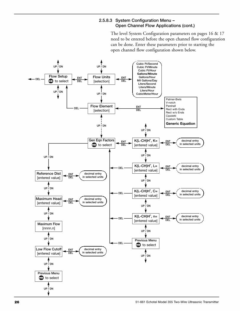
2.5.8.3 System Configuration Menu –Open Channel Flow Applications (cont.)
The level System Configuration parameters on pages 16 &17 need to be entered before the open channel flowconfiguration can be done. Enter these parameters prior tostarting the open channel flow configuration shown below.
Note: Maximum Flowis a read-only value.
Flow Units[selection]
UP / DN
ENTDEL
UP / DN
Flow Element[selection]
UP / DN
ENTDEL
DEL
Palmer-Bwls4", 6", 8", 10", 12", 15"18", 21", 24", 27", 30"
V-Notch22.5º, 30º, 45º, 60º,
90º, 120º
Parshall1", 2", 3", 6", 9", 12",18", 24", 36", 48", 60",72", 96", 120", 144"
Rect with Ends
Rect w/o Ends
Cipoletti
Generic Equation
Custom Table
Crest Length[entered value]
UP / DN
ENTDEL
DEL
Reference Dist[entered value]
UP / DN
ENTDEL
DELdecimal entryin selected units
Maximum Head[entered value]
UP / DN
ENTDEL
DEL
Maximum Flow[nnnn.n]
UP / DN
DEL
Low Flow Cutoff[entered value]
UP / DN
ENTDEL
DELdecimal entryin selected units
Previous Menu
to selectDEL
ENTDEL
Flow Setup
to select
UP / DN
UP / DN
DEL
UP / DN
decimal entryin selected units
decimal entryin selected units
Cubic Ft/SecondCubic Ft/MinuteCubic Ft/HourGallons/MinuteGallons/HourMil Gallons/DayLiters/SecondLiters/MinuteLiters/Hour
CubicMeter/Hour

51-661 Echotel Model 355 Two-Wire Ultrasonic Transmitter 25
2.5.8.3 System Configuration Menu –Open Channel Flow Applications (cont.)
The following table provides an explanation of each of theSystem Configuration parameters for open channel flowapplications using one of the Flow Elements that are storedin the firmware. See below and page 23 for dimensionalinformation on the flumes and weirs.
Configuration Parameter Explanation (Open Channel Flow Applications)
Flow Units A selection of Gallons/Minute (factory default Flow Unit), Gallons/Hour, MilGallons/Day, Liters/Second, Liters/Minute, Liters/Hour, Cubic Meter/Hour,Cubic Ft/Second, Cubic Ft/Minute, and Cubic Ft/Hour are provided. Shouldsome other units of flow be desired, the Custom Unit feature can be used in theAdvanced Configuration Menu.
Flow Element Select one of the following primary Flow Elements that are stored in the firmware:Parshall flume sizes of 1", 2", 3", 6", 9", 12", 18", 24", 36", 48", 60", 72", 96",120" and 144". Palmer-Bwls (Palmer-Bowlus) flume sizes of 4", 6", 8", 10", 12",15", 18", 21", 24", 27" and 30”. V-notch weir sizes of 22.5O, 30O, 45O, 60O, 90O and120O. Rect with Ends (Rectangular Weir with End Contractions), Rect w/o Ends(Rectangular Weir without End Contractions), and Cipoletti weir. Custom Table (seepage 28) can be selected if none of the stored Flow Elements can be used. Thetable can be built with a maximum of 20 points. The 355 also has the capability ofinputting a Generic Equation (see page 26) for flow calculation.
Crest Length The Crest Length screen only appears when the chosen Flow Element is Cipolettior one of the Rectangular weirs. Input this length in the user-selected level units.
Reference Dist The Reference Distance is measured from the face of transducer to the point ofzero flow in the weir or flume. This must be measured very accurately in the user-selected level units. For some Flow Elements, such as Parshall flumes, theReference Dist is the same as the Range value. Weirs and some other FlowElements will have a Reference Distance that is shorter than the Range value.
Maximum Head Maximum Head is the highest liquid level (Head) value in the flume or weir beforethe flow equation is no longer valid. The Maximum Head is expressed in the user-selected Level Units. The 355 will default to the largest Maximum Head value thatis allowed for any given flume or weir. The Maximum Head value can be reviseddepending on the value of the Reference Distance, or for end user preference.
Maximum Flow Maximum Flow is a read-only value that represents the flow value correspondingto the Maximum Head value for the flume or weir.
Low Flow Cutoff The Low Flow Cutoff (in user-selected level units) will force the calculated flowvalue to zero whenever the Head is below this point. This parameter will have adefault and minimum value of zero.
Previous Menu Previous Menu exits the flow Open Channel Flow Config menu.
26 51-661 Echotel Model 355 Two-Wire Ultrasonic Transmitter
2.5.8.3 System Configuration Menu –Open Channel Flow Applications (cont.)
The level System Configuration parameters on pages 16 & 17need to be entered before the open channel flow configurationcan be done. Enter these parameters prior to starting theopen channel flow configuration shown below.
Palmer-BwlsV-notchParshallRect with EndsRect w/o EndsCipolettiCustom Table
Generic Equation
UP / DN
K(L-CH)Hn, K=[entered value]
UP / DN
ENTDEL
K(L-CH)Hn, L=[entered value]
UP / DN
ENTDEL
DELdecimal entryin selected units
K(L-CH)Hn, C=[entered value]
UP / DN
ENTDEL
DEL
K(L-CH)Hn, n=[entered value]
UP / DN
DEL
decimal entryin selected units
decimal entryin selected units
ENTDEL
decimal entryin selected units
Previous Menu
to select
UP / DN
DEL
Gen Eqn Factorsto select
ENTDEL
UP / DN
Flow Units[selection]
UP / DN
ENTDEL
Flow Element[selection]
UP / DN
DEL
ENTDEL
UP / DN
Flow Setupto select
UP / DN
DEL
Cubic Ft/SecondCubic Ft/MinuteCubic Ft/HourGallons/MinuteGallons/HourMil Gallons/DayLiters/SecondLiters/MinuteLiters/Hour
CubicMeter/Hour
Reference Dist[entered value]
UP / DN
ENTDEL
Maximum Head[entered value]
UP / DN
ENTDEL
decimal entryin selected units
Maximum Flow[nnnn.n]
UP / DN
Low Flow Cutoff[entered value]
UP / DN
decimal entryin selected units
ENTDEL
decimal entryin selected units
Previous Menu
to select
UP / DN
UP / DN
ENTDEL

51-661 Echotel Model 355 Two-Wire Ultrasonic Transmitter 27
2.5.8.3 System Configuration Menu –Open Channel Flow Applications (cont.)
The following table provides an explanation of each of theSystem Configuration parameters for open channel flowapplications using the Generic Equation.
Configuration Parameter Explanation (Open Channel Flow Applications using the Generic Equation)
Flow Units A selection of Gallons/Minute (factory default Flow Unit), Gallons/Hour,Mil Gallons/Day, Liters/Second, Liters/Minute, Liters/Hour, Cubic Meter/Hour,Cubic Ft/Second, Cubic Ft/Minute, and Cubic Ft/Hour are provided. Shouldsome other units of flow be desired, the Custom Unit feature can be used in theAdvanced Configuration Menu.
Flow Element If none of the stored Flow Elements can be used, either a Custom Table can bebuilt with a maximum of 20 points, or a Generic Equation can be entered thatcalculates the flow discharge rate.
Generic Eqn Factors Generic Equation is a discharge flow equation in the form of Q = K(L-CH)Hn, whereQ = flow (Cu Ft/Second), H = Head (Feet), K = a constant, and L, C and n are userinput factors that depend on which Flow Element is being used. Make sure the flowequation is in the form of Q = K(L-CH)Hn, and proceed to enter the values of K,L,C,Hand n. See example below.
Note: The Generic Equation parameters must be entered in Cu Ft/Second units. The resultant flow isconverted by the 355 into whatever Flow Units are selected above. See example below.
Reference Dist The Reference Distance is measured from the face of the transducer to the pointof zero flow in the weir or flume. This must be measured very accurately in theuser-selected level units. For some Flow Elements, the Reference Dist is the sameas the Range value. Weirs and some other Flow Elements, will have a ReferenceDistance that is shorter than the Range value.
Maximum Head Maximum Head is the highest liquid level (Head) value in the flume or weir beforethe flow equation is no longer valid. The Maximum Head is expressed in the user-selected level units. The 355 will default to the largest Maximum Head value thatis allowed for any given flume or weir. The Maximum Head value can be reviseddepending on the value of the Reference Distance, or for end user preference.
Maximum Flow Maximum Flow is a read-only value that represents the flow value correspondingto the Maximum Head value for the flume or weir.
Low Flow Cutoff The Low Flow Cutoff (in user-selected level units) will force the calculated flowvalue to zero whenever the Head is below this point. This parameter will have adefault and minimum value of zero.
Previous Menu Previous Menu exits the flow Open Channel Flow Config menu.
Using the factors above the equation becomes:
Q = 3.33 (8-0.2H) H1.5
The discharge flow value for a Head value of 3 feet becomes128.04 Cubic Ft/Second. If GPM was selected for the FlowUnits, the 355 Measured Values screen would display thisvalue converted to 57,490 GPM.
Generic Equation Example (using equation for an 8' rectangular weir w/ end contractions)
Q = Cubic Ft/Second flow rate L = 8' (weir crest length in feet) H = Head value
K = 3.33 for Cubic Ft/Second units C = 0.2 (constant) n = 1.5 as an exponent
Q = K(L-CH)Hn

28 51-661 Echotel Model 355 Two-Wire Ultrasonic Transmitter
2.5.8.3 System Configuration Menu –Open Channel Flow Applications (cont.)
The level System Configuration parameters on pages 16 & 17need to be entered before the open channel flow configurationcan be done. Enter these parameters prior to starting the openchannel flow configuration shown below.
Flow Units[selection]
ENTDEL
UP / DNGallons/MinuteGallons/HourMil Gallons/DayLiters/SecondLiters/MinuteLiters/Hour
CubicMeter/HourCubic Ft/SecondCubic Ft/MinuteCubic Ft/Hour
Flow Element[selection]
UP / DN
ENTDEL
DEL
UP / DN
Cust Table Type[selection]
UP / DN
ENTDEL
DEL LinearSpline
Cust Table Valsnn Points
UP / DN
ENTDEL
DEL
UP / DN
UP / DN
Point nn Head[entered value]
Point nn Flow[entered value]
ENT ENT
ENTDEL
Flow Setupto select
DEL
Palmer-BwlsV-notchParshallRect with EndsRect w/o EndsCipolettiGeneric EqnCustom Table
Reference Dist[entered value]
UP / DN
ENTDEL
Maximum Head[entered value]
UP / DN
ENTDEL
decimal entryin selected units
Maximum Flow[nnnn.n]
UP / DN
Low Flow Cutoff[entered value]
UP / DN
decimal entryin selected units
ENTDEL
decimal entryin selected units
Previous Menu
to select
UP / DN

51-661 Echotel Model 355 Two-Wire Ultrasonic Transmitter 29
2.5.8.3 System Configuration Menu –Open Channel Flow Applications (cont.)
The following table provides an explanation of each ofthe System Configuration parameters for open channelflow applications using the Custom Table.
Configuration Parameter Explanation (Open Channel Flow Applications using the Custom Table)
Flow Units A selection of Gallons/Minute (factory default Flow Unit), Gallons/Hour,Mil Gallons/Day, Liters/Second, Liters/Minute, Liters/Hour, Cubic Meters/Hour,Cubic Ft/Second, Cubic Ft/Minute, and Cubic Ft/Hour are provided. Shouldsome other units of flow be desired, the Custom Unit feature can be used in theAdvanced Configuration Menu.
Flow Element If none of the stored Flow Elements can be used, either a Custom Table can bebuilt with a maximum of 20 points, or a Generic Equation can be entered thatcalculates the flow discharge rate.
Custom Table The Custom Table points can be a Linear (straight line between adjacent points) orSpline (can be a curved line between points) relationship. See above drawing formore information.
Cust Table Vals A maximum of 20 points can be used in building the Custom Table. Each pair of val-ues will have a Head (height) in the units chosen in the Level Units screen, and theassociated flow for that Head value. The values must be monotonic, i.e., each pairof values must be greater than the previous Head/flow pair. The last pair of valuesshould have the highest Head value (usually the Maximum Head value) and the flowassociated with that Head value.
Reference Dist The Reference Distance is measured from the face of transducer to the point ofzero flow in the weir or flume. This must be measured very accurately in the user-selected level units. For some Flow Elements, the Reference Dist is the same asthe Range value. Weirs and some other Flow Elements, will have a ReferenceDistance that is shorter than the Range value.
Maximum Head Maximum Head is the highest liquid level (Head) value in the flume or weir beforethe flow equation is no longer valid. The Maximum Head is expressed in the user-selected Level Units. The 355 will default to the largest Maximum Head value thatis allowed for any given flume or weir. The Maximum Head value can be reviseddepending on the value of the Reference Distance, or for end user preference.
Maximum Flow Maximum Flow is a read-only value that represents the flow value correspondingto the Maximum Head value for the flume or weir.
Low Flow Cutoff The Low Flow Cutoff (in user-selected level units) will force the calculated flowvalue to zero whenever the Head is below this point. This parameter will have adefault and minimum value of zero.
Previous Menu Previous Menu exits the flow Open Channel Flow Config menu.
SPLINE OR LINEAR
SPLINEP1
P2
P3
P4
P5
Concentrate points along curve
P2
P3
P7
P10Transition point
P1
Concentrate points as follows:A. At least two points at beginning (P1 and P2); B. At least two points at end (P9 and P10); C.Three points at approximate average flow rate (for example, P3, P4, P5); and at transition point (P7) and points on either side (P6, P8).
P5P4
P6
P8
P9
Average flow rate

30 51-661 Echotel Model 355 Two-Wire Ultrasonic Transmitter
2.5.9 I/O Configuration Menu
The I/O Configuration Menu is used to set the 4-20 mA current loop values, the totalizer parameters,and the HART polling address. The totalizer screens only appear if the unit is being configured foropen channel flow.
UP / DN
Controlled By[selection]
UP / DN
ENTDEL
4 mA Set Point[entered value]
UP / DN
ENTDEL
DELdecimal entryin selected units
20 mA Set Point[entered value]
UP / DN
ENTDEL
DEL
System Fault[selection]
UP / DN
DEL
decimal entryin selected units
LevelVolumeFlow
ENTDEL
Previous Menuto select
UP / DN
DEL
ENTDEL
UP / DN
4-20 mA Configto select
ENTDEL
UP / DN
I/O Configto select
UP / DN
Totalizersto select
ENTDEL
DEL
HART Poll Addr[entered value]
UP / DN
DEL ENTDEL
[inc/dec]0-15
Previous Menuto select
UP / DN
DEL
22 mA3.6 mAHold
Note: See page 32 for Totalizer configuration

51-661 Echotel Model 355 Two-Wire Ultrasonic Transmitter 31
2.5.9 I/O Configuration Menu (cont.)
The opposite page shows the I/O Configuration Menu that isbeing used for configuring the 4-20 mA setpoints, and theHART polling address. If the 355 is being used for open channelflow, see pages 32 & 33 to configure totalizers.
Configuration Parameter Explanation (4-20 mA Configuration)
Controlled By The Controlled By screen sets which measurements (Level, Volume or Flow) willcontrol the mA loop output, and also determines which will be the PrimaryVariable (PV). The Controlled By screen will not allow the existing value to bechanged to a new value that is inconsistent with the chosen Measure Type (select-ed in the System Configuration Menu). It will revert to the original value in suchcases.
4 mA Set Point Enter the desired value for the 4 mA Set Point in the measurement units selectedabove in the Controlled By screen. Note that during normal operation the mA valuewill never read into the Level Offset area that was configured on page 17.
20 mA Set Point Enter the desired value for the 20 mA Set Point in the measurement units selectedabove in the Controlled By screen. Note that during normal operation the mA valuewill never read into the Blocking Distance area that was configured on page 17.
System Fault Select 3.6 mA, 22 mA, or Hold (last value).
Previous Menu Previous Menu exits the 4–20 mA Config menu.
Configuration Parameter Explanation (Totalizers & HART Poll Address)
Totalizers This screen will only appear if the 355 is being configured as an open channelflow transmitter. See pages 32 & 33 for the totalizer configuration screens.
HART Poll Addr Select a HART Poll Address from 0–15. Enter 0 for a single transmitter installation.Enter 1–15 for a multi-drop network.
Previous Menu Previous Menu exits the 4–20 mA Config menu.

32 51-661 Echotel Model 355 Two-Wire Ultrasonic Transmitter
2.5.9 I/O Configuration Menu (cont.)
The I/O Configuration Menu screens below are used to configure the totalizers when the 355 is beingused for open channel flow.
Totalizer Units[selection]
UP / DN
ENTDEL
UP / DN
Total NR Mult[selection]
UP / DN
ENTDEL
DEL
Totalizer NRnn.nn e+mm units
UP / DN
UP / DN
UP / DN
UP / DN
DEL
Total NR Timennnnn.n hrs
DEL
Total R Mode[selection]
UP / DN
ENTDEL
DEL
Total R Mult[selection]
DEL
Totalizer Rnn.nn e+mm units
DEL
Total R Timennnnn.n hrs
DEL
ENTDEL
Totalizersto select
UP / DN
UP / DN
DisabledEnabled
Cubic FeetGallons
Mil GallonsLiters
Mil LitersCubic Meters
Totalizer RReset
UP / DN
ENTDEL
DEL
Previous Menu
to selectDEL
ENTDEL
1101001,00010,000100,000
Are you sure?[selection]
YESNO
ENTDEL
UP / DN
UP / DN
1101001,00010,000100,000
ENTDEL

51-661 Echotel Model 355 Two-Wire Ultrasonic Transmitter 33
2.5.9 I/O Configuration Menu (cont.)
The I/O Configuration Menu screens below are used toconfigure the totalizers when the 355 is being used for openchannel flow.
Configuration Parameter Explanation (NR & R Totalizers)
Totalizer Units The Totalizer Units screen is for selection of the units for both the resettable andnon-resettable totalizers. Select Gallons (factory default unit) Mil Gallons, Liters,Mil Liters, Cubic Meters, or Cubic Feet.
Total NR Mult The Total NR Mult screen allows selection of the multiplier to be used for the non-resettable totalizer. The function of the totalizer multiplier is such that if the chosenunits are gallons and the multiplier is 100, the totalizer value will increment onewhole unit for each 100 gallons. Select 1, 10, 100, 1,000 (factory default multiplier),10,000 or 100,000.
Totalizer NR This is a read only screen that displays the present value of the non-resettabletotalizer.
Total NR Time This is a read only screen that displays the time that has elapsed since the non-resettable totalizer has been totalizing flow.
Total R Mode Total R Mode allows the user to enable and disable the resettable totalizer. Thedefault mode is disabled.
Total R Mult The Total R Mult screen allows selection of the multiplier to be used for the reset-table totalizer. The function of the totalizer multiplier is such that if the chosenunits are gallons and the multiplier is 100, the totalizer value will increment onewhole unit for each 100 gallons. Select 1, 10, 100, 1,000 (factory default multiplier),10,000 or 100,000.
Totalizer R This is a read-only screen that displays the present value of the resettable totalizer.
Total R Time This is a read-only screen that displays the time that has elapsed since the reset-table totalizer has been totalizing flow.
Totalizer R Reset The Totalizer R Reset screen allows the user to reset the total flow and elapsedtime of Totalizer R to zero (Totalizer NR is non-resettable). Since this action willpermanently lose this data, a second chance is provided with an “Are you sure?”screen.
Previous Menu Previous Menu exits the Totalizer configuration.

34 51-661 Echotel Model 355 Two-Wire Ultrasonic Transmitter
2.5.10 Advanced Configuration Menu
The Advanced Configuration Menu contains items that most users will not need to configure for typicallevel, volume and flow applications. The figure below shows the first eight menu screens of the AdvancedConfiguration Menu. Page 36 shows the last eight menu screens, and page 38 shows the Echo Profilesubmenu.
UP / DN
Input Local Tag[entered value]
UP / DN
ENTDEL
alphanumeric entry(12 chars)
Damping[entered value]
UP / DN
ENTDEL
DEL
Echo Loss Delay[entered value]
UP / DN
DEL
[incr/dec]1-60
ENTDEL
[incr/dec]1-300 seconds
Echo Loss Fault[selection]
UP / DN
ENTDEL
DEL22 mA3.6 mAHold
Trim 4 mA[value]
UP / DN
ENTDEL
DEL
Trim 20 mA[value]
UP / DN
DEL
[incr/dec]
ENTDEL
[incr/dec]
Custom Unit Text[entered value]
UP / DN
ENTDEL
DEL
Custom Unit Mult[entered value]
UP / DN
DEL
alphanumeric entry(3 chars)
ENTDEL
decimal entryin selected units
Advanced Config
to select
UP / DN
UP / DN
ENTDEL

51-661 Echotel Model 355 Two-Wire Ultrasonic Transmitter 35
2.5.10 Advanced Configuration Menu (cont.)
The opposite page shows the first eight menu screens of the AdvancedConfiguration Menu. The following table provides an explanation ofthose parameters.
Configuration Parameter Explanation
Input Local Tag From the factory this tag is shown as “Model 355,” but this can be changed todescribe the vessel tag number, loop number, or anything else. The tag can con-tain a maximum of 12 characters. All upper and lower case letters, numbers and29 other characters are provided for the tag.
Damping Increasing the Damping value will smooth the 355 display and/or the loop output ifturbulence or other difficult application conditions are present. The default setting is5, and this parameter can be set anywhere from 1–60.
Echo Loss Delay Depending on the application, the 355 may temporarily lose the echo from the liq-uid surface. The Echo Loss Delay feature allows the transmitter additional time toreacquire the echo and keep a stable loop output. The default setting is 30 sec-onds, and this parameter can be set anywhere from 1–300 seconds.
Echo Loss Fault This is the value the loop will go to after the 355 has lost the echo and the echo losstimer has expired. Select 22 mA (factory default value), 3.6 mA, or Hold (last value).
Trim 4 mA This allows fine tuning of the 4 mA point. Since this is done at the factory, theuser should not need to trim this value. If desired, attach a meter to the outputand adjust the 5 digit value found in the Trim 4 mA screen until the meter reads4.00 mA.
Trim 20 mA This allows fine tuning of the 20 mA point. Since this is done at the factory, theuser should not need to trim this value. If desired, attach a meter to the outputand adjust the 5 digit value found in the Trim 20 mA screen until the meter reads20.00 mA.
Custom Unit Text The 355 has the capability to display a custom level, volume or flow unit if the userdesires a unit that is not in the transmitter firmware. This could be millimeters, bar-rels, cubic meters/day, or any other unit. Custom Unit Text allows a 3-characterabbreviation of the desired unit, which can be displayed along with the Custom Unitvalue on the Home Menu. See example below.
Custom Unit Mult This multiplier is used to derive the Custom Unit value that can be shown on theHome Menu. The Custom Unit value is equal to the Primary Variable (selected via theControlled By screen in I/O Config) times the Custom Unit Mult. See example below.
Custom Unit Example (millimeters)
Controlled By (PV) = Level Custom Unit Text = mm Custom Unit Mult = 10.0
If Level = 460.8 cm Custom Unit Value = 4608.00 mm
NOTE: The resolution of the Model 355 is not improved by the use of custom units. Refer to PerformanceSpecifications for expected resolution.

36 51-661 Echotel Model 355 Two-Wire Ultrasonic Transmitter
2.5.10 Advanced Configuration Menu (cont.)
The Advanced Configuration Menu contains items that most users will not need to configure for typicallevel, volume and flow applications. The figure below shows eight of the menu screens. The Echo Profilesubmenu screens are detailed starting on page 38.
UP / DN
Echo Profile
to select
UP / DN
ENTDEL
Target Algorithm[selection]
UP / DN
ENTDEL
DEL
Temp Comp[selection]
UP / DN
DEL
Largest AmplitudeFirst TargetAmplitude/Dist
ENTDEL
OnFixed
Temp Offset[entered value]
UP / DN
ENTDEL
DEL[incr/dec]
in selected units
Speed of Sound[entered value]
UP / DN
ENTDEL
DEL
New Password[entered value]
UP / DN
DEL
decimal entry
ENTDEL
decimal entry
ConfigurationReset
UP / DN
ENTDEL
DEL
Previous Menu
to select
UP / DN
DEL
Advanced Config
to select
UP / DN
UP / DN
ENTDEL
Are you sure?[selection]
ENTDEL
NoYes
See page 38 for Echo Profile submenu

51-661 Echotel Model 355 Two-Wire Ultrasonic Transmitter 37
2.5.10 Advanced Configuration Menu (cont.)
The table below provides an explanation of the AdvancedConfiguration Menu screens from the opposite page.
Configuration Parameter Explanation
Echo Profile The Echo Profile submenu screens are shown on the next page.
Target Algorithm The 355 has the capability of operating under three different Target Algorithm modesfor acquiring the proper echo from the liquid surface. For almost all applications, thefactory default of First Target is best for echo processing. Consult the factory foruse of these algorithms.
Temp Comp Since the speed of sound varies with temperature, the 355 provides temperaturecompensation for the air space between the transducer and the liquid surface.This Temp Comp feature should always be On. The Fixed mode should only beused if the temperature sensor has been damaged. Consult the factory for use ofthe Fixed mode.
Temp Offset Temp Offset is used in conjunction with the Temp Comp feature. Consult the factoryfor use of this parameter.
Speed of Sound The Speed of Sound through air is 331.45 meters/second at 0º C. Ultrasonictransmitters are generally not used in applications that have vapors other than air,since stratified layers of vapors develop that have different speed of sound propa-gation rates. Exceptions to this are tanks that have a homogenous gas (e.g., nitro-gen) blanket. Consult the factory for use of this parameter.
New Password The default password is 0, which effectively disables the password feature. Thisallows the configuration to be done without entering a password. If desired, a dif-ferent password can be entered in the New Password screen. The password canbe changed to any numerical value up to 255. If the password is changed fromthe factory default value of 0, then the new password will be required wheneverany configuration values are changed.
NOTE: If the password is not known, the New Password screen displays an encrypted value representing thepresent password. Call the factory with this encrypted value to determine the actual password.
Configuration Reset The Configuration Reset screen can be used if it is determined that the configurationhas been entered erroneously and it is desired to bring all configuration parametersback to their default values. Consult the factory for use of this parameter.
Previous Menu Previous Menu exits the Advanced Config menu.

38 51-661 Echotel Model 355 Two-Wire Ultrasonic Transmitter
2.5.10 Advanced Configuration Menu (cont.)
The Advanced Configuration Menu contains items that most users will not need to configure for typicallevel, volume and flow applications. The figure below shows the screens for the Echo Profile submenu, shouldit be necessary to establish an echo rejection curve.
UP / DN
Echo List Mode[selection]
UP / DN
ENTDEL
No Echoes
UP / DN
DEL
Dist 1 Str XX[value]
UP / DN
DEL
Dist 2 Str XX[value]
UP / DN
ENTNo/DEL
DEL
Enter Distance[entered value]
UP / DN
DEL
Saved Distance @[value]
UP / DN
DEL
Echo Rej Status[value]
UP / DN
ENTDEL
DEL
Previous Menu
to select
UP / DN
DEL
Echo Profile
to select
UP / DN
UP / DN
ENTDEL
Presented only whenno echoes exist.
Processing
PROCESS ABORTEDEcho Too Strong
AnyKey
PROCESS ABORTEDEcho Too Close
Yes
Save Echo Rej?No/Yes
No
Dist Correct?No/Yes
NoneDisabledEnabled
Echo screens are presentonly when associatedechoes exist. Sorted in
order of ascending distance.
Level wil be displayed on screensinstead of Distance (or Dist) whenEcho List Mode is set to Level.
DistanceLevel
AnyKey

51-661 Echotel Model 355 Two-Wire Ultrasonic Transmitter 39
2.5.10 Advanced Configuration Menu (cont.)
The table below provides an explanation of the Echo Profile submenuscreens shown on the opposite page. Two notes are worth pointing out:
1. If possible, the best answer to resolve issues deriving from falseechoes in the tank is to reposition the 355 in a different mount-ing where the false echoes are eliminated or reduced.
2. This submenu can also be used to simply view a list of existingechoes (correct and/or false) for diagnostic purposes.
Configuration Parameter Explanation (Echo Profile submenu)
Echo Profile The Echo Profile submenu contains parameters that can be used to manage thefalse target rejection functionality of the transmitter.
Echo List Mode The Echo List Mode screen allows a selection of Distance (factory default) or Level.This specifies whether the echoes presented in this submenu are in relation to theirDistance from the face of the transducer, or in terms of Level in the tank.
No Echoes The No Echoes screen is only displayed when the 355 cannot detect any echoesat all.
Note: The example below shows typical screens that might be presented if the Echo List Mode is Distance andthe Level Units are inches.
Dist 1 Str 4523.9 in
If echoes are detected (correct and/or false) from one to nine echoes will be pre-sented. The correct echo is usually the one that shows the highest Strength (Str)value. In the example on the left, the first echo may be an obstruction in the ultra-sonic beam, the second echo is the correct one, and the third may be a second-ary echo coming from the liquid surface.
Dist 2 Str 7075.3 in
Dist 3 Str 22151.8 in
Enter Distance If the correct echo is not listed, and it is still desired to create a new EchoRejection Curve, the exact liquid distance or level can be entered in the EnterDistance (or Enter Level) screen.
Note: If no echoes are shown, it is advised to check the mounting location and to review the application, asopposed to manually entering the distance or level in this screen.
Dist Correct? If desired, a new Echo Rejection Curve can be established by pressing ENTER onthe echo screen that represents the current liquid distance or level. Upon pressingENTER the Dist Correct? Screen will be presented. A selection of Yes or No isoffered to make sure that the echo is the correct one.
Save Echo Rej? If Yes was selected in the Dist Correct? screen, then the Save Echo Rej? screenappears. This screen allows one more chance to abort creating a new EchoRejection Curve, if it has not been confirmed that the selected echo is the correctecho from the liquid surface.
(Table continues on next page.)

40 51-661 Echotel Model 355 Two-Wire Ultrasonic Transmitter
2.5.10 Advanced Configuration Menu (cont.)
Configuration Parameter Explanation (Echo Profile submenu)
Processing If No is selected in Save Echo Rej?, the process is aborted and the transmitterreturns to the main Echo Profile submenu screen. If Yes is selected, and no errorsare detected, a “progress-bar” Processing screen is shown while the transmitterprocesses, stores, and enables the new Echo Rejection Curve. It is not possibleto leave this screen until the Processing has been completed (this may take 30seconds or longer). Once complete, the 355 returns to the main Echo Profile sub-menu screen. If an error occurs, “PROCESS ABORTED” will be displayed on theupper line along with “Echo Too Close” or “Echo Too Strong” on the lower line.This may indicate that the vessel is too full to process an Echo Rejection Curve.Another Echo Rejection curve should be attempted after the level is reduced inthe vessel.
Saved Distance @ The Saved Distance/Level @ screen displays the distance (or level) at which theexisting Echo Rejection Curve was created. This screen is only presented when avalid Echo Rejection Curve exists.
Echo Rej Status The Echo Rej Status screen displays the current status (None, Disabled, orEnabled) of the Echo Rejection Curve. The factory default value of None indicatesthat an Echo Rejection Curve does not exist or was invalidated. Pressing ENTERwhen the Echo Rej Status is None has no effect since it cannot be Enabled orDisabled. If an Echo Rejection Curve has been created, then it can be Disabledor Enabled by pressing ENTER. Selecting Disabled will disengage an existingEcho Rejection Curve without affecting the stored profile. Once Disabled it ispossible to view false echoes and decide if it is necessary to run a new EchoRejection Curve.
Previous Menu Previous Menu exits the Echo Profile submenu.

51-661 Echotel Model 355 Two-Wire Ultrasonic Transmitter 41
2.5.11 Diagnostics Menu
The Diagnostics Menu contains both informational items and diagnostic screens that can assist introubleshooting the 355 if faults or warnings occur.
Present current loop value isshown in mA. The mA can beincremented/decremented after
Enter is pressed.
UP / DN
Test 4-20 Loop[current value]
UP / DN
ENTDEL
Echo Strength[value]
UP / DN
DEL
Number of Echoes[value]
UP / DN
DEL
[incr/dec]
Echo Missing[value] sec
UP / DN
DEL
Echo Rej WarningReset
UP / DN
ENTDEL
DEL
Safe Zone AlarmReset
UP / DN
DEL ENTDEL
Max Temperature[max value]
UP / DN
DEL
Min Temperature[min value]
UP / DN
DEL
Diagnostics
to select
UP / DN
UP / DN
ENTDEL
Reset?[selection]
ENTDEL
NoYes
Reset?[selection]
ENTDEL
NoYes

42 51-661 Echotel Model 355 Two-Wire Ultrasonic Transmitter
2.5.11 Diagnostics Menu (cont.)
The table below provides an explanation of the first eight items in theDiagnostics Menu. The remaining screens of the Diagnostic Menu areshown on the next page.
Configuration Parameter Explanation
Test 4-20 Loop This screen allows any value from 3.6 to 22.0 mA to be entered to test the loopoutput.
Echo Strength This parameter is an indication of the relative strength of the echo identified as thecorrect echo coming from the target or liquid surface. The Echo Strength valuevaries from 0 (echo loss) to 100.
Number of Echos The 355 can process as many as 9 echos at a time and still keep track of thecorrect echo from the liquid surface. This parameter shows the Number of Echosthe transmitter is detecting.
Echo Missing The 355 can lose the echo for as long as the Echo Loss Delay period that is set inAdvanced Configuration prior to going into the Echo Loss Fault condition. TheEcho Missing screen shows how many seconds have passed since the echo hasbeen lost.
Echo Rej WarningReset
A warning message will be displayed on the Home Menu screen if a non-volatilememory exception has corrupted the Echo Rejection Curve, or if this curve hasbeen invalidated. The curve can become invalidated if one of the key configura-tion parameters was changed after the curve was set up. This Echo Rej WarningReset screen allows a reset of this warning message, so that it can be removedfrom the Home Menu. A new Echo Rejection Curve should be run and saved.
Safe Zone AlarmReset
If liquid level enters the Safe Zone Height (see System Configuration) and the SafeZone Fault has been set to either 3.6 mA, 22 mA, Latch 3.6 mA or Latch 22 mAthen “SafeZoneAlrm” will be displayed on the LCD. Once liquid level has droppedbelow Safe Zone Height, the alarm will clear unless the Latch feature has beenselected. The Safe Zone Alarm Reset screen allows this latching to be reset afterthe liquid level has fallen out of the Safe Zone Height area.
Max Temperature This parameter displays the maximum transducer temperature ever recorded.
Min Temperature This parameter displays the minimum transducer temperature ever recorded.

51-661 Echotel Model 355 Two-Wire Ultrasonic Transmitter 43
2.5.11 Diagnostics Menu (cont.)
The Diagnostics Menu contains both informational items and diagnostic screens that can assist introubleshooting the 355 if faults or warnings occur.
UP / DN
History[current status]
UP / DN
ENTDEL
Run Timexxxx.x hrs
UP / DN
DEL
HistoryReset
UP / DN
DEL
Magnetrol S/N[value]
UP / DN
DEL
Model 355 HTVer 1.0 A
UP / DN
DEL
Previous Menu
to select
UP / DN
DEL
Diagnostics
to select
UP / DN
UP / DN
ENTDEL
Event nn[diagnostic Text]
ENTDEL
Event nn Occurredxxxx.x hrs
UP / DN
Event nn Durationxxxx.x hrs
Previous Menu
to select
UP / DN
ENTDEL
Reset?[selection]
ENTDEL
NoYes
ENTDEL
ENTDEL
Run-time since lastpower-up. Zeroed when
History is reset.

44 51-661 Echotel Model 355 Two-Wire Ultrasonic Transmitter
2.5.11 Diagnostics Menu (cont.)
The table below provides an explanation of the remaining screens ofthe Diagnostic Menu.
Configuration Parameter Explanation
History The History screen displays the present status and the sequence in which anydiagnostic events may have occurred. The 2nd line of the menu shows the pres-ent status. If there are no present diagnostic events, this screen will have Historyon the top line and OK on the bottom line. Pressing descends to a lower
menu level to view diagnostic events that have been logged in History. Each“Event” is indicated by the event number label. The first event number label pre-sented corresponds to the most recent diagnostic event. This event number alsoindicates the number of diagnostic events currently in the History submenu. Up to10 events can be stored in the History submenu. It is also possible to display therelative time of occurrence and the duration of each event. This is done with athird menu level displayed by pressing again.
Run Time The Run Time screen shows how much time has elapsed since the 355 transmitterhas been powered up.
History Reset The History Reset screen provides a means to clear all of the diagnostics eventsthat are stored in the History log.
Magnetrol S/N This read-only screen displays the serial number of the unit.
Model 355 HTVer 1.0a
If the “HT” is shown on the top line of this read only screen, the 355 has HART digi-tal communications capability. If “NP” (No Protocol) is shown on the top line, thenthe transmitter does not have HART. The bottom line displays the firmware version.
Previous Menu Previous Menu exits the Diagnostic Menu.

51-661 Echotel Model 355 Two-Wire Ultrasonic Transmitter 45
2.5.12 Factory Configuration Menu
The Factory Configuration Menu contains items that cannot be configured without assistance from thefactory. Contact the factory if any of these parameters need to be modified.
UP / DN
Peak Threshold[entered value]
UP / DN
# Run Average[selection]
UP / DN
DEL
TVG[selection]
UP / DN
DEL
NSP Value[entered value]
UP / DN
DEL
FactoryReset
UP / DN
DEL
HART Device ID[entered value]
UP / DN
DEL
DELPrevious Menu
to select
UP / DN
Factory Config
to select
UP / DN
UP / DN
ENTDEL
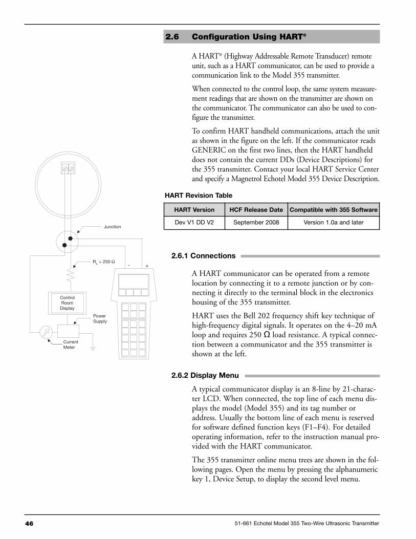
46 51-661 Echotel Model 355 Two-Wire Ultrasonic Transmitter
2.6 Configuration Using HART®
A HART® (Highway Addressable Remote Transducer) remoteunit, such as a HART communicator, can be used to provide acommunication link to the Model 355 transmitter.
When connected to the control loop, the same system measure-ment readings that are shown on the transmitter are shown onthe communicator. The communicator can also be used to con-figure the transmitter.
To confirm HART handheld communications, attach the unitas shown in the figure on the left. If the communicator readsGENERIC on the first two lines, then the HART handhelddoes not contain the current DDs (Device Descriptions) forthe 355 transmitter. Contact your local HART Service Centerand specify a Magnetrol Echotel Model 355 Device Description.
2.6.1 Connections
A HART communicator can be operated from a remotelocation by connecting it to a remote junction or by con-necting it directly to the terminal block in the electronicshousing of the 355 transmitter.
HART uses the Bell 202 frequency shift key technique ofhigh-frequency digital signals. It operates on the 4–20 mAloop and requires 250 Ω load resistance. A typical connec-tion between a communicator and the 355 transmitter isshown at the left.
2.6.2 Display Menu
A typical communicator display is an 8-line by 21-charac-ter LCD. When connected, the top line of each menu dis-plays the model (Model 355) and its tag number oraddress. Usually the bottom line of each menu is reservedfor software defined function keys (F1–F4). For detailedoperating information, refer to the instruction manual pro-vided with the HART communicator.
The 355 transmitter online menu trees are shown in the fol-lowing pages. Open the menu by pressing the alphanumerickey 1, Device Setup, to display the second level menu.
+-
Junction
RL > 250 Ω
ControlRoom
Display
PowerSupply
CurrentMeter
HART Revision Table
HART Version HCF Release Date Compatible with 355 Software
Dev V1 DD V2 September 2008 Version 1.0a and later

51-661 Echotel Model 355 Two-Wire Ultrasonic Transmitter 47
1 SystemConfiguration
2 I/OConfiguration
3 AdvancedConfiguration
4 Diagnostics
5 FactoryConfiguration
6 DeviceDescription
7 Review
8 Date/Time/Initials
1 MeasurementType
2 Level Units3 Range4 BlockingDistance
5 Safe Zone Fault6 Safe ZoneHeight
7 Level Offset8 Trim Level9 Flow Setup
10 Volume Setup
1 Flow Units2 Flow Element3 Crest Length4 ReferenceDistance
5 Maximum Flow6 Maximum Head7 Low Flow Cutoff8 Generic EquationFactors
9 Flow CustomTable
1 Volume Units2 Vessel Type3 VesselDimensions
4 VolumeCustom Table
1 K2 L3 C4 n5 Flow=K(L-CH)H^n whereH = Head
1 Table Type2 Table Length3 Pt 01 Head4 Pt 01 Flow…..41 Pt 20 Head42 Pt 20 Flow
1 Vessel Radius2 Ellipse Height3 Conical Height4 Vessel Width5 Vessel Length6 Ellipse End
1 Table Type2 Table Length3 Pt 01 Level4 Pt 01 Volume…..43 Pt 20 Level44 Pt 20 Volume
1 PV is2 VariableSelection
3 4-20mASetpoints
4 System Fault5 Poll Address6 Totalizers
1 SV is2 TV is3 4V is
1 PV 4mASet Point
2 PV 20mASet Point
1 Totalizer Units2 NR TotalizerMultiplier
3 NR Totalizer4 NR TotalizerTime
5 R Totalizer Mode6 R TotalizerMultiplier
7 R Totalizer8 R Totalizer Time9 Reset Totalizer
1 Local Tag2 Damping3 Echo Loss Delay4 Echo Loss Fault5 Trim Loop Current6 Custom Unit Text7 Custom Unit Multiplier8 Echo Profile
9 Enter Password10 Target Algorithm11 Temperature
Compensation Mode12 Temperature Offset13 Speed of Sound14 New User Password15 Reset Configuration
1 Echo List Mode2 Refresh Echo List3 Echo 1 Location4 Echo 1 Strength5 Echo 2 Location6 Echo 2 Strength…..19 Echo 9 Location20 Echo 9 Strength21 Saved Media Location22 Echo Rejection Status23 New Echo
Rejection Profile
1 Device Setup
2 PV3 % Output4 Loop Current5 Device Variables
2.6.3 HART Menu

48 51-661 Echotel Model 355 Two-Wire Ultrasonic Transmitter
2.6.3 HART Menu (cont.)
1 Loop Test2 Echo Strength3 Number ofEchoes
4 Echo Missing5 Reset EchoRejectionWarning
6 Reset SafeZone Alarm
7 Temperature8 MaxTemperature
9 MinTemperature
10 ResetTemperatures
11 FirmwareVersion
12 Status History
13 Present Status
1 Enter Password2 Peak Threshold3 # Run Average4 TVG5 Factory Param 16 Factory Param 27 NSP Value8 Reset FactoryDefaults
1 Tag2 Magnetrol S/N3 Descriptor4 Date5 Message6 Finalasmbly num
7 Device ID
1 View History2 Reset History
1 System params default2 Adv Cfg params default3 I/O params default4 Fact Cfg params default5 HART params default6 Custm Tbl params dflt7 Totalizer params default8 Configuration Conflict9 Hardware Failure10 Loop Failure11 Temperature Failure12 Blocking Distance13 High Volume Alarm14 High Flow Alarm15 Safe Zone Alarm16 Echo Lost
1 Warning 12 Low VDC 20mA3 Noise4 Hi Temperature5 Lo Temperature6 Echo RejectionProfile Corrupt
7 Echo RejectionProfile Invalid
8 Initializing9 System Warning
1 SystemConfiguration
2 I/OConfiguration
3 AdvancedConfiguration
4 Diagnostics
5 FactoryConfiguration
6 DeviceDescription
7 Review
8 Date/Time/Initials
1 Device Setup
2 PV3 % Output4 Loop Current5 Device Variables
1 Faults
2 Warnings

51-661 Echotel Model 355 Two-Wire Ultrasonic Transmitter 49
3.0 Reference Information
This section contains information on troubleshooting,agency approvals, spare parts, and detailed physical, func-tional and performance specifications.
3.1 Troubleshooting
The Model 355 transmitter is designed and engineered fortrouble-free operation over a wide range of operating condi-tions. Common transmitter problems are discussed in termsof their symptoms and recommended corrective actions.
WARNING! Explosion hazard. Do not remove the 355 housing coverunless power has been switched off or the area is knownto be nonhazardous. Use of the included PACTware™ PCprogram is highly recommended and invaluable for trou-bleshooting and advanced configuration. A HART RS232or USB modem (purchased separately) is required. SeeMagnetrol PACTware™ bulletin 59-101.
2.6.3 HART Menu (cont.)
1 Level2 Volume3 Flow4 Head5 Distance6 NR Totalizer7 R Totalizer8 Transducer Temp9 Custom Unit
1 Model2 Manufacturer3 Magnetrol S/N4 Firmware Version5 Tag6 Descriptor7 Date8 Message9 Local Tag10 Date/Time/Initials11 Final asmbly num12 Device ID13Poll Address14 Universal rev15 Fld Dev rev16 Software rev17 Num req preams18 Measurement Type19 Level Units20 Range21 Level Offset22 Blocking Distance23 Trim Level24 Volume Units25 Vessel Type26 Vessel Radius27 Ellipse Height
28 Conical Height29 Vessel Width30 Vessel Length31 Ellipse End32 Flow Units33 Flow Element34 Crest Length35 Reference Distance36 Maximum Flow37 Maximum Head38 Low Flow Cutoff39 K40 L41 C42 n43 PV is44 SV is45 TV is46 4V is47 PV 4mA
Set Point48 PV 20mA
Set Point49 PV Min Span50 4 mA Trim Value51 20mA Trim Value52 System Fault
53 Totalizer Units54 NR Totalizer
Multiplier55 R Totalizer Mode56 R Totalizer
Multiplier57 Damping58 Safe Zone Fault59 Safe Zone Height60 Echo Loss Delay61 Echo Loss Fault62 Custom Unit Text63 Custom Unit
Multiplier64 Target Algorithm65 Temperature
Compensation Mode66 Temperature Offset67 Speed of Sound68 Echo List Mode69 Echo
Rejection Status70 Peak Threshold71 # Run Average72 TVG73 Factory Parameter 174 Factory Parameter 2
1 SystemConfiguration
2 I/OConfiguration
3 AdvancedConfiguration
4 Diagnostics
5 FactoryConfiguration
6 DeviceDescription
7 Review
8 Date/Time/Initials
1 Device Setup
2 PV3 % Output4 Loop Current5 Device Variables

50 51-661 Echotel Model 355 Two-Wire Ultrasonic Transmitter
3.1.2 Error Messages
The Echotel 355 transmitter utilizes a 3-level hierarchy forreporting diagnostic conditions: FAULTS, WARNINGS,and INFORMATION. Faults and Warnings can bereviewed in the rotating screens in the Home menu. Thesescreens capture only current conditions. Historical diagnos-tic information can be viewed at the HISTORY screen inthe Diagnostic Menu.
FAULT: The highest level in the hierarchy of diagnostics. AFault annunciates a defect or failure in the circuitry or soft-ware that makes reliable measurement impossible. The cur-rent (mA) value unit defaults to 3.6, 22, or HOLD and amessage is displayed on the rotating screen. Further errorinformation can be obtained by reviewing the DiagnosticMenu screens.
WARNING (MESSAGE): This is the second level in thehierarchy of diagnostics. A Warning annunciates conditionsthat are not fatal but may affect measurement. A messagewill occur on the Home (rotating) screen when a Warning isdetected but will not affect output current. Further errorinformation can be obtained by reviewing the DiagnosticMenu screens.
INFORMATION (MESSAGE): This is the lowest level inthe hierarchy of diagnostics. Information messages are forconditions that provide operational factors that are not criti-cal to measurement. Further error information can beobtained by reviewing the Diagnostic Menu screens.
Symptom Problem Solution
Level reading locked onto avalue that is not correct level
Measurement engine finding areflection it believes is thecorrect level signal
Run an Echo Rejection Curve with the Level belowthis point (or with empty tank) to eliminate falseechoes
LEVEL, % Output and LOOPvalues are all inaccurate
Basic configuration data may bequestionable
1. Check validity of all configuration data2. Check DISTANCE value of device againstmanually measured distance
LEVEL readings are repeatable butconsistently high (or low) fromactual by a fixed amount
Configuration data does notaccurately match tankdimensions
1. Ensure proper values for Range2. Check vessel for present liquid level. Trim Levelcan be used to ensure exact measurement
3. Reconfigure LOOP values if necessary
LEVEL reading on Display is cor-rect but LOOP is stuck at 4 mA
HART Poll Address set avalue of 1-15
Set HART Poll Address to 0
LEVEL reading on Displaystuck at value related toBlocking Distance
The 355 believes the transduceris flooded (level very near or ontransducer)
Check actual level. If transducer is not flooded, powerdown, then power-up transmitter with the level wellbelow the transducer. Increase the Blocking Distance.
3.1.1 Troubleshooting System Problems

51-661 Echotel Model 355 Two-Wire Ultrasonic Transmitter 51
Diagnostic Fault Description LCD Message
Non-VolatileMemory Exceptions
a) System Config parameters defaultedb) Advanced Config parameters defaultedc) I/O Config parameters defaultedd) Factory Config parameters defaultede) HART parameters defaultedf) Strapping Table parameters defaultedg) Totalizer parameters defaulted
DfltParm SysDfltParm AdvDflt Parm I/ODfltParmFactDfltParmHARTDfltCustmTblDfltParm Tot
I/O Configuration Measurement Type and Loop Controlled By selections are incompatible(e.g., Flow selected for control but is not being calculated).
CnfgConflict
Hardware Failure The "HardwareFail" fault will be indicated if there is a hardware failure.Contact the factory for assistance.
HardwareFail
Loop Failure The actual current generated in the 4–20 mA loop differs significantly(>1 mA) from the intended loop current.
Loop Failure
TemperatureSensor Failure
A short or open in the connection to the temperature sensor. Temp Failure
Block Dist Elevated signals are impinging on the Blocking Distance point. This mayor may not be caused by excessive ringing of the transducer.
Block Dist
High Volume/FlowAlarm
The measured level exceeds the highest level in the strapping table bymore than 5%, or the applicable range of the equations / data setsinvolved.
HiVolumeAlrmHi Flow Alrm
Safe Zone Alarm The level has risen to within the configured Safe Zone region in the tank. SafeZoneAlrm
Echo Lost No valid echo from the liquid surface has been received for a periodexceeding the Echo Loss Delay.
Echo Lost
3.1.2 Error Messages
Diagnostic Warning Description LCD Message
Low Loop Voltage The transmitter’s minimum voltage requirement may not be met when theloop is driven to 22.0 mA.
LowVDC@20mA
Noise Spurious signals similar in magnitude to echoes are detected. Noise
Temp LimitsExceeded
The transducer temperature exceeds +80°C or –40°C. High TempLow Temp
Corrupt EchoRejection Partition
Non-Volatile Memory exception for Echo Rejection partition. EchoRej Crpt
Invalid EchoRejection Curve
A stored Echo Rejection Curve has been invalidated (usually because akey configuration parameter was changed).
EchoRej Invl
Initial Startup Displayed during “warm-up” period. Initializing
Diagnostic Diagnostic Information Description LCD Message
Echo Strength A numerical indication of the relative strength of the echo identified as theliquid surface.
Echo Strength xx
Number of Echos The number of echoes detected. Number of Echos
Echo Missing The duration (in seconds) that echoes have been missing. Echo Missing xx sec
TemperatureExtrema
Maximum and minimum measured temperatures will be stored in non-volatile memory, resettable only by the factory.
Min Temp xxx °F/CMax Temp xxx °F/C
Echo Profile A means to display the attributes of all the echos detected in thereceive signal.
Refer to Advanced ConfigMenu

52 51-661 Echotel Model 355 Two-Wire Ultrasonic Transmitter
3.2 Measurement Range Calculations
Ultrasonic non-contact transmitters are typically rated fora maximum range in ideal conditions. Experience hasshown that maximum range must be reduced for certainfactors. Although the maximum range rating is somewhatconservative, each application must be evaluated for specificconditions in the tank.
Several application parameters that affect ultrasonicperformance are shown in the tank at the left. Each ofthese parameters is assigned a Performance Multiplier inthe chart below. Multiply the maximum potential range(20 feet or 6 meters) of the Model 355 by each of theapplicable Performance Multipliers to calculate the maxi-mum allowable range for the application.
Beam spreadinterference
Beam spreadinterference
Vapors
FoamSurfaceagitation
EXAMPLE: A slightly agitated 12-foot tank with no condensation, no interference, and a light froth on the surface.
Maximum allowable range: 20' × 0.9 × 1.0 × 1.0 × 0.8 = 14.4 feetSince the maximum allowable range is 14.4 feet, the 355 is suitable for this 12-foot tank.
PerformanceOperating parameter Condition MultiplierSURFACE AGITATION: Surface agitation or waves can degrade the Smooth, glass-like surface . . . . . . . . . . . . . . . . . . . . .1.0performance. Moderate agitation results in only slight degradation of Slight agitation, choppiness . . . . . . . . . . . . . . . . . . .0.9performance. The worst case is when the surface is a good reflector, but Heavy agitation . . . . . . . . . . . . . . . . . . . . . . . . . . . .0.8in the wrong direction. Slight vortex . . . . . . . . . . . . . . . . . . . . . . . . . . . . . . .0.7VAPORS AND STEAM: Vapors can cause problems when the liquid No condensation . . . . . . . . . . . . . . . . . . . . . . . . . . .1.0process temperature is well above the temperature of the airspace. The Little condensation . . . . . . . . . . . . . . . . . . . . . . . . . .0.9greater the difference, the more expected vapor problems. The problems Much condensation / foggy appearance . . . . . . . . . .0.8result from condensation or layering in the sound path, both of whichattenuate the sound signal, and degrade performance. If a vent is used,be sure that it is well away from the transducer.BEAM SPREAD INTERFERENCE: It is recommended that no No interference within 5° half beam angle . . . . . . . .1.0obstructions, such as ladder rungs, fill pipes, support struts, etc., be Agitator at speed less than 60 RPM . . . . . . . . . . . . .1.0allowed within the 10° ultrasonic beam. If an obstruction is unavoidable, Agitator at speed greater than 60 RPM . . . . . . . .C/Fmake it as far away as possible from the transducer. Interference from Interference outside 2°, . . . . . . . . . . . . . . . . . . . . . .0.8agitator blades is only an intermittent interference that usually has little far from transducer (in bottom third of range)effect on performance. A special software algorithm can also help Interference outside 2°, . . . . . . . . . . . . . . . . . . . . . .0.5suppress false echoes from agitator blades that are within the beam angle. near to transducer (in top third of range)FOAM: Foam can attenuate the ultrasound and render the system No foam . . . . . . . . . . . . . . . . . . . . . . . . . . . . . . . . . .1.0inoperative. If possible, moving the transducer to an area in the tank Light froth, less than 0.25" thick . . . . . . . . . . . . . . .0.8where there is less foam will improve the performance. Thick, Light foam, less than 0.5" thick . . . . . . . . . . . . . . . .0.5heavy-density foams can sometimes produce a reflection from the top Light foam, more than 1" thick . . . . . . . . . . . . . . . .0.1of the foam.
NOTE: The multipliers shown above are general guidelines.For further assistance consult the factory.

51-661 Echotel Model 355 Two-Wire Ultrasonic Transmitter 53
3.3 Speed of Sound Through Gases
The speed of sound through air is 331.45 meters/sec (1,087feet/sec) at 0° C (+32° F) as indicated in Section 2.5.10. Thisspeed is the basis for all measurements made by the Model355 transmitter. The table below contains the speed of soundfor various gases measured @ +32° F (0° C). These valuescan be used to alter the speed of sound value in Section2.5.10. This should only be done if the gas exists as ahomogeneous layer (such as a nitrogen blanket) in the tank.
3.4 Replacement Parts
Gases Chemical Formula Velocity (m/s)Argon Ar 307
Carbon monoxide CO 337Methane CH4 433Methanol CH3OH 335Neon Ne 435Nitrogen N2 334
Nitrous oxide N2O 263Oxygen O2 316Propane C3H8 235
1
3
4
2
1X 742 3 8 9 105 6Digit in partn°:
Partn°:
Serial n°:
X = product with a specific customer requirement
See nameplate, always provide complete partn° andserial n° when ordering spares.
(2) Electronic moduleDigit 5 Digit 9 Replacement part
0 0 or 1 089-9125-0016 or 7 089-9125-002
1 0 or 1 089-9125-0036 or 7 089-9125-004
(1) Housing coverDigit 9 Replacement part0 or 1 036-4410-0106 or 7 003-1226-003
(3) "O"-ringDigit 9 Replacement part0 or 1 012-2201-2376 or 7 012-2616-237

54 51-661 Echotel Model 355 Two-Wire Ultrasonic Transmitter
3.5 Agency Approvals
FM 355-5X0A-11R Intrinsically Safe Class I, Div. 1; Groups A, B, C, & D355-5X0A-10R Type 4X, IP66, T4 @80°C
Entity355-5X0A-1XX Intrinsically Safe Class I, Div. 1; Groups A, B, C, & D
IP67, T4 @80°C
Entity355-5X0A-1XX Non-Incendive Class I, Div. 2; Groups A, B, C, & D
IP67, T4 @80°C
ATEX 355-5X0A-AXX Intrinsically Safe ATEX II 1 G Ex ia IIC T4 @70°CISSeP09ATEX013X(EN 60079-0, EN 60079-11& EN 60079-26 standards applied)
355-5X0A-C0X Flameproof Enclosure ATEX II 1/2 G Ex ma/d IIC T6 @70°C Ga/Gb355-5X0A-C1X ISSeP09ATEX009X (EN 60079-0,
EN 60079-1, EN 60079-18 & EN 60079-26standards applied)
AGENCY MODEL PROTECTION METHOD AREA CLASSIFICATION
C US
These units have been tested toEN 61326 and are in compliance withthe EMC Directive 2004/108/EC.
Measured media inside vessel must be non-flammable only. Process temperature must not increase the internaltemperature of the electronics above 176° F (80° C).
Refer to Section 2.3 for special Conditions for Safe Use
(4) Transducer + housing baseDigit 8 Digit 9 Digit 10 Replacement part
1 or A
0 B 089-9126-001R 089-9126-002
1 B 089-9126-003R 089-9126-004
6 B 089-9126-009R 089-9126-010
7 B 089-9126-011R 089-9126-012
C0 B 089-9126-007
R 089-9126-005
1 B 089-9126-008R 089-9126-006

51-661 Echotel Model 355 Two-Wire Ultrasonic Transmitter 55
3.5.1 Agency (FM/FMc) Drawing and Entity Parameters

56 51-661 Echotel Model 355 Two-Wire Ultrasonic Transmitter
3.6 Specifications
3.6.1 Transmitter
Supply Voltage XP & GP 16 to 36 VDC
IS 16 to 28.6 VDC
IS Entity Parameters FM/FMc Vmax = 28.6 V, Imax = 140 mA
Pmax = 1.0 W, Ci = 5.5 nF, Li = 9.4 µH
ATEX Ui = 28.4 V, li = 94 mA, Pi = 0.67 W
Ci = 5.5 nF, Li = 370 µH
Power Consumption Less than 1 Watt
Output:
Type 4–20 mA with optional HART digital signal
Range 3.8 to 20.5 mA useable
Diagnostic Alarm Selectable from 3.6 mA, 22 mA or HOLD
Damping Adjustable from 1–60
Digital Communication HART version 5.x compatible
Display 2-line x 16-character LCD
Keypad 4-pushbutton menu-driven
Ambient Temperature -40° to +175° F (-40° to +80° C)
Housing Material Cast aluminum or Lexan
Cable Entry Two ¾" NPT or M20 entries
3.6.2 Transducer
Maximum Range 20 feet (6 meters)
Minimum Range 13 inches (330 mm)
Blocking Distance 10 inches (250 mm)
Frequency 60 kHz
Process Connection 2" NPT
Process Temperature -40º to +175º F (-40º to +80º C)
Process Pressure 0 to 43.5 psig (0 to 3 bar)
Material Kynar Flex (PVDF) or polypropylene
Beam Angle 10º conical
3.6.3 Performance
Accuracy Greater of ± 0.2% of range or 0.24 inch (6 mm)
Repeatability ± 0.125 inch (± 3 mm)
Resolution 0.1 inch (2.5 mm)
Linearity ± 0.4 inch (±10 mm)
Response Time Less than 1 second (typical)
Warm-up Time 30 seconds
Performance is based on a reference operating condition of an ambient temperature of +60º to +77º F (+15º to + 25º C),45 to 75% relative humidity, transducer vertically aligned over an ideal reflecting surface, and no false targets within theultrasonic beam angle.
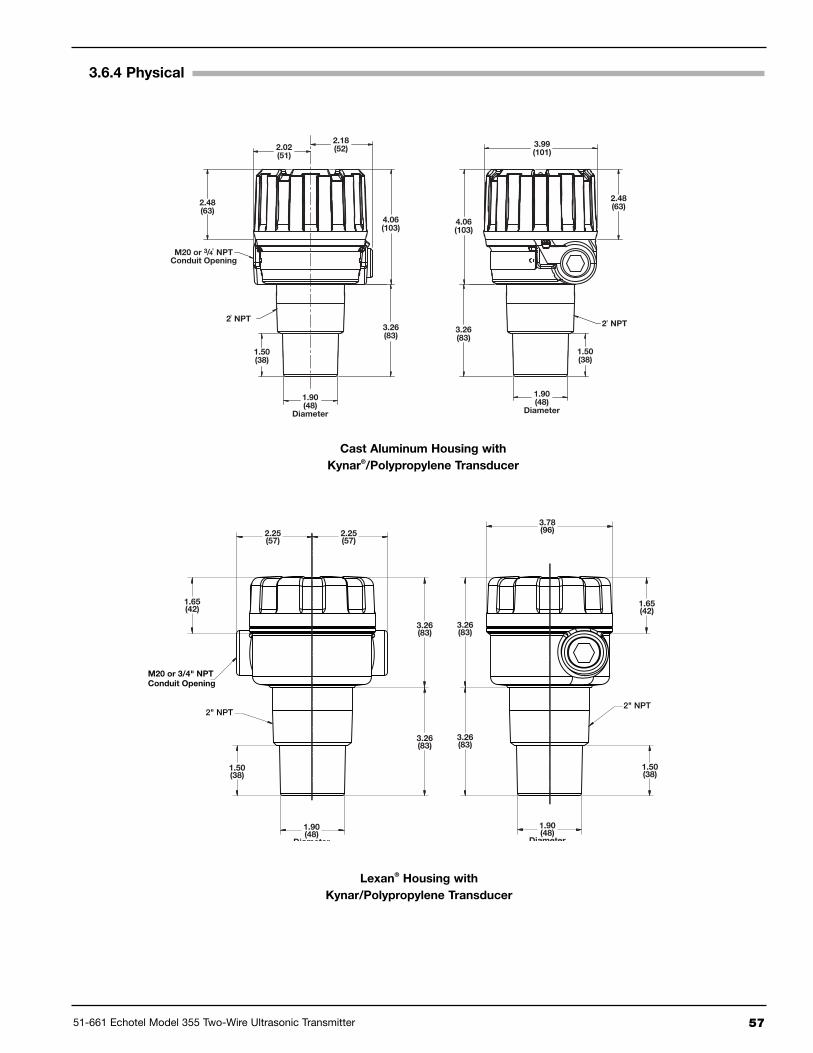
51-661 Echotel Model 355 Two-Wire Ultrasonic Transmitter 57
3.6.4 Physical
2.02(51)
2.18(52)
M20 or 3/4" NPTConduit Opening
2.48(63)
1.50(38)
2" NPT
1.90(48)
Diameter
3.26(83)
4.06(103)
3.99(101)
2.48(63)
1.50(38)
2" NPT
1.90(48)
Diameter
3.26(83)
4.06(103)
Cast Aluminum Housing withKynar®/Polypropylene Transducer
2" NPT
M20 or 3/4" NPTConduit Opening
3.26(83)
3.26(83)
1.65(42)
1.50(38)
1.90(48)
Diameter
3.78(96)
2" NPT
1.65(42)
2.25(57)
2.25(57)
3.26(83)
3.26(83)
1.90(48)
Diameter
1.50(38)
Lexan® Housing withKynar/Polypropylene Transducer

3.7 Model Number
58 51-661 Echotel Model 355 Two-Wire Ultrasonic Transmitter
3 A055 5 complete code for Echotel 355 transmitter
BASIC MODEL NUMBER
ACCESSORIES
3 5 5 - 5 1 24 V DC 2-wire loop powered ultrasonic non contact transmitter with HART®
3 5 5 - 5 0 24 V DC 2-wire loop powered ultrasonic non contact transmitter without HART®
0 A Digital display and keypad
MOUNTING / APPROVAL1 Integral mount, WeatherproofA Integral mount, ATEX intrinsically safeC Integral mount, ATEX flameproof enclosure (not available with Lexan® plastic housing)
TRANSDUCERB 60 kHz, Polypropylene, 2" NPT process connectionR 60 kHz, Kynar Flex®, 2" NPT process connection
HOUSING / CABLE ENTRY0 IP 66, Cast aluminium, 3/4" NPT cable entry (2 entries - 1 plugged)1 IP 66, Cast aluminium, M20 x 1,5 cable entry (2 entries - 1 plugged)6 IP 66, Lexan® plastic, 3/4" NPT cable entry (2 entries - 1 plugged)7 IP 66, Lexan® plastic, M20 x 1,5 cable entry (single entry)
X = product with a specific customer requirement.

51-661 Echotel Model 355 Two-Wire Ultrasonic Transmitter 59
Echotel Model 355 TransmitterConfiguration Data Sheet
-SYSTEM CONFIGURATIONDefault Value Present Value
Measure Type Level OnlyLevel Units InchesRange 240.0"Blocking Dist 10"Safe Zone Fault NoneSafe Zone Height 2"Level Offset 0.0"Trim Level 0.0"
Flow Setup Default Value Present Value
Flow Units Gallons/MinuteFlow Element Parshall 1"Reference Dist 120.0"Low Flow Cutoff 0.0"
DIAGNOSTICS MENU
Default Value Present Value
Echo StrengthNumber of EchoesMax/Min TemperatureRun TimeMagnetrol S/NModel 355 Version
Value ValueLevelVolumeFlowHeadDistance% Output
I/O CONFIGURATIONDefault Value Present Value
Controlled By Level4 mA Set Point 0.0"20 mA Set Point 230.0"System Fault 22 mATotalizer Units GallonsTotal NR Mult 1000Total R Mode DisabledTotal R Mult 1000
ADVANCED CONFIGURATIONDefault Value Present Value
Input Local Tag Model 355Damping 5Echo Profile See table below for Echo ProfileTarget Algorithm First Target
FACTORY CONFIGURATIONDefault Value Present Value
Peak Threshold 18# Run Average 8TVG 2HART Device ID
HISTORY (IN DIAGNOSTIC MENU)Event # and Event Occurred Duration12345678910
ECHO LIST (ECHO PROFILE IN ADVANCED CONFIG)Dist/Level Echo # Strength Value Dist/Level Value123456789
Value ValueLoop CurrentLocal TagTemperatureTotalizer RTotalizer NRCustom Units
MEASURED VALUES

IMPORTANTSERVICE POLICY
Owners of Magnetrol products may request the return of a control; or, any part of a control for complete rebuilding or replacement.They will be rebuilt or replaced promptly. Magnetrol International will repair or replace the control, at no cost to the purchaser, (orowner) other than transportation cost if:
a. Returned within the warranty period; and,b. The factory inspection finds the cause of the malfunction to be defective material or workmanship.
If the trouble is the result of conditions beyond our control; or, is NOT covered by the warranty, there will be charges for labour andthe parts required to rebuild or replace the equipment.In some cases, it may be expedient to ship replacement parts; or, in extreme cases a complete new control, to replace the originalequipment before it is returned. If this is desired, notify the factory of both the model and serial numbers of the control to be replaced.In such cases, credit for the materials returned, will be determined on the basis of the applicability of our warranty.No claims for misapplication, labour, direct or consequential damage will be allowed.
RETURNED MATERIAL PROCEDURESo that we may efficiently process any materials that are returned, it is essential that a “Return Material Authorisation” (RMA) formwill be obtained from the factory. It is mandatory that this form will be attached to each material returned. This form is availablethrough Magnetrolʼs local representative or by contacting the factory. Please supply the following information:
1. Purchaser Name2. Description of Material3. Serial Number and Ref Number4. Desired Action5. Reason for Return6. Process details
Any unit that was used in a process must be properly cleaned in accordance with the proper health and safety standards applica-ble by the owner, before it is returned to the factory.A material Safety Data Sheet (MSDS) must be attached at the outside of the transport crate or box.All shipments returned to the factory must be by prepaid transportation. Magnetrol will not accept collect shipments.All replacements will be shipped Ex Works.
www.magnetrol.com
BENELUX Heikensstraat 6, 9240 Zele, België -BelgiqueFRANCE Tel. +32 (0)52.45.11.11 • Fax. +32 (0)52.45.09.93 • E-Mail: [email protected] Alte Ziegelei 2-4, D-51491 Overath Tel. +49 (0)2204 / 9536-0 • Fax. +49 (0)2204 / 9536-53 • E-Mail: [email protected] C-20 Community Centre, Janakpuri, New Delhi - 110 0058
Tel. +91 (11) 41661840 • Fax +91 (11) 41661843 • E-Mail: [email protected] Via Arese 12, I-20159 Milano
Tel. +39 02 607.22.98 (R.A.) • Fax. +39 02 668.66.52 • E-Mail: [email protected]. DAFZA Office 5EA 722 • PO Box 293671 • Dubai Tel. +971-4-6091735 • Fax +971-4-6091736 • E-Mail: [email protected] Unit 1 Regent Business Centre, Jubilee Road Burgess Hill West Sussex RH 15 9TLKINGDOM Tel. +44 (0)1444 871313 • Fax +44 (0)1444 871317 • E-Mail: [email protected]
BULLETIN N°: BE 51-661.1EFFECTIVE: MAY 2010SUPERSEDES: September 2009UNDER RESERVE OF MODIFICATIONS