ecet 211 electric machines & controls lecture 2-3 (part 3 ...lin/ecet211/spring2016/1... ·...
TRANSCRIPT

1
1
ECET 211 Electric Machines & Controls
Lecture 2-3 (Part 3 of 3)
Symbols and Drawing for Electric Motor
Control SystemsText Book: Chapter 2. Understanding Electrical Drawings, Electric
Motors and Control Systems, by Frank D. Petruzella, published
by McGraw Hill, 2015.
Paul I-Hai Lin, Professor of Electrical and Computer
P.E. states of Indiana & California
Dept. of Computer, Electrical and Information Technology
Purdue University Fort Wayne Campus
Prof. Paul Lin
2. Symbols and Drawings for Electric Motor
Control Systems Chapter 2. Understanding Electrical Drawings
• Part 1. Symbols-Abbreviations-Ladder Diagram
• Part 2. Wiring – Single – Block Diagrams
• Part 3. Motor Terminal Connections
• Part 4. Motor Nameplates and Terminology
• Part 5. Manual and Magnetic Motor Starter
Prof. Paul Lin 2

2
Part 4. Motor Nameplate and Terminology
NEC (National Electrical Code) Required Nameplate
Information
• Motor Manufacturer
• Voltage Rating
• Current Rating
• Line Frequency
• Phase Rating
• Motor Speed
• Ambient Temperature
• Temperature Rise
• Insulation Class
• Duty Cycle
• Horsepower Rating
• Code Letter
• Design Letter
Prof. Paul Lin 3
Voltage Rating
NEMA standard motor voltages:
• Single-phase motors: 115, 230, 115/230, 277, 460 and
230/460 V
• Three-phase motor up to 125 HP: 208, 230, 460, 230/460,
575, 2300, and 4000 V
• Three-phase motor above 125 HP: 460, 575, 2300, and 4000
V
Prof. Paul Lin 4
Nominal System Voltage Nameplate Voltage
120 V 115 V
208 V 200 V
240 V 230 V
480 V 460 V
600 V 575 V
2,400 V 2,300 V
4,100 V 4,000 V
6,900 V 6,600 V

3
NEC Requirement Nameplate Information
Current Rating
• Current unit: AMPs or A
• Nameplate rating: full-load current at rated load, rated
voltage, and rated frequency
• Not fully loaded – draw less current
• Overloaded – draw more than the rated current
• Dual voltage motors => Dual current rating
115/230 V, 7.4/3.7 A
Prof. Paul Lin 5
NEC Requirement Nameplate Information
Frequency (Hertz, Hz)
• 60 Hz – in the U.S
• 50 Hz – in other countries
A MATLAB voltage plot: nominal system voltage 120V,
peak voltage 170V; f = 60Hz, T = 1/60 = 16.7 ms
Prof. Paul Lin 60 0.005 0.01 0.015 0.02 0.025 0.03 0.035-200
-150
-100
-50
0
50
100
150
200
time Second
Volts
4
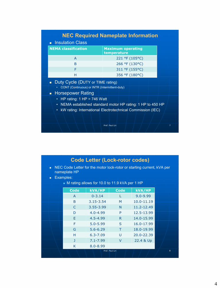
NEC Required Nameplate Information
Insulation Class
Duty Cycle (DUTY or TIME rating)
• CONT (Continuous) or INTR (Intermittent-duty)
Horsepower Rating
• HP rating: 1 HP = 746 Watt
• NEMA established standard motor HP rating: 1 HP to 450 HP
• kW rating: International Electrotechnical Commission (IEC)
Prof. Paul Lin 7
NEMA classification Maximum operatingtemperature
A 221 °F (105°C)
B 266 °F (130°C)
F 311 °F (155°C)
H 356 °F (180°C)
Code Letter (Lock-rotor codes)
NEC Code Letter for the motor lock-rotor or starting current, kVA per
nameplate HP
Examples:
M rating allows for 10.0 to 11.9 kVA per 1 HP
Prof. Paul Lin 8
Code kVA/HP Code kVA/HP
A 0-3.14 L 9.0-9.99
B 3.15-3.54 M 10.0-11.19
C 3.55-3.99 N 11.2-12.49
D 4.0-4.99 P 12.5-13.99
E 4.5-4.99 R 14.0-15.99
F 5.0-5.99 S 16.0-17.99
G 5.6-6.29 T 18.0-19.99
H 6.3-7.09 U 20.0-22.39
J 7.1-7.99 V 22.4 & Up
K 8.0-8.99

5
Design Letter
Five standard designs for polyphase induction motors
• A, B, C, D, E
• Indication of the shape of the motor’s torque-speed curve
• Design B
Standard industrial-type motor which has
• reasonable starting torque with moderate current and
good overall performance
Prof. Paul Lin 9
Optional Nameplate Information Service Factor (SF) – overload factor
• 1.0, 1.15, and 1.25
• 10 HP motor, SF 1.25 => 12.5 HP overload occasionally
Motor Enclosure
Frame Size
Efficiency
Power Factor
Thermal Protection
Connection Diagram
Prof. Paul Lin 10
Figure 2-40 Totally enclosed motor
Figure 2-41 Typical NEMA frame and dimensions

6
Optional Nameplate Information Efficiency
• η = (Power output/ Power input) * 100%
Power Factor (P.F.)
• Motor – Inductive Load, PF in the range of 0.5 to 0.95
• P.F. = cosθ; the angle θ between voltage and current
• P = V*I* PF (Single phase)
• P = 1.732 * V*I* PF (Three phase)
Thermal Protection
Connection Diagram
Prof. Paul Lin 11
Figure 2-42 Typical dual-voltage motor connection diagram
Guide to Motor Terminology
Across-the-line
Automatic starter
Auxiliary contact
Contactor
Jog
Lock-rotor-current
Low-voltage protection (LVP)
Low-voltage release (LVR)
Magnetic contactor
Multispeed starter
Prof. Paul Lin 12

7
Guide to Motor Terminology
Prof. Paul Lin 13
Overload relay
Plugging
Push button
Reduced voltage starter
Relay
Remote control
Selector switch
Slip
Starter
Timer
Part 5. Manual and Magnetic Motor Starters Figure 2-45 Manual motor starter
• Motor Control Circuit with manual “START” and “STOP”
button
Prof. Paul Lin 14

8
Figure 2-47 Two-wire control circuit
Prof. Paul Lin 15
Figure 2-48 Three-wire control circuit
Prof. Paul Lin 16
