ecet 211 electric machines & controls lecture 2-1 (part 1...
TRANSCRIPT
1
1
ECET 211 Electric Machines & Controls
Lecture 2-1 (Part 1 of 3)
Symbols and Drawing for Electric Motor Control Systems
Text Book: Chapter 2. Understanding Electrical Drawings, Electric Motors and Control Systems, by Frank D. Petruzella, published
by McGraw Hill, 2015.
Paul I-Hai Lin
Professor of Electrical and Computer Engineering TechnologyP.E. states of Indiana & California
Dept. of Computer, Electrical and Information Technology
Purdue University Fort Wayne Campus
Prof. Paul Lin
2. Symbols and Drawings for Electric Motor Control Systems
Chapter 2. Understanding Electrical Drawings
Part 1. Symbols-Abbreviations-Ladder Diagram• Motor Symbols
• Abbreviations for Motor Terms
• Motor Ladder Diagrams
Part 2. Wiring – Single – Block Diagrams
Part 3. Motor Terminal Connections
Part 4. Motor Nameplates and Terminology
Part 5. Manual and Magnetic Motor Starter
Prof. Paul Lin 2

2
2. Symbols and Drawings for Electric Motor Control Systems
Chapter 2. Understanding Electrical Drawings
Abbreviations and Symbols for Motor TermsPower Source
• PWR - Power
• AC – Alternating Current
• 3PH – three phase• 1PH – single phase• DC – Direct Current
• NEG - Negative• POS - Positive• REC - Rectifier• TRANS - Transformer
Prof. Paul Lin 3
2. Symbols and Drawings for Electric Motor Control Systems
1PH 120V 60Hz sinewave power source (max 15 A)
MATLAB script for generating & plotting the waveformVp = 120*sqrt(2); %Vp = 120* 1.414 = 169.68 volts
f = 60; % 60 Hz, 60 sine waves per second
T = 1/f; % Period T = 1/f = 1/60 = 16.67 ms
dt = T/100; % Take 100 samples per one period
t = 0: dt: 2*T; % Plot for two cycles
vt = Vp* sin(2*pi*f*t);
plot(t, vt), grid on;
xlabel(' time - second');
ylabel('volts');
Prof. Paul Lin 40 0.005 0.01 0.015 0.02 0.025 0.03 0.035
-200
-150
-100
-50
0
50
100
150
200
time - second
vol
t
3
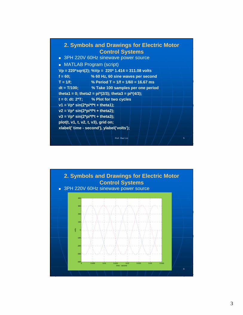
2. Symbols and Drawings for Electric Motor Control Systems
3PH 220V 60Hz sinewave power source
MATLAB Program (script)Vp = 220*sqrt(2); %Vp = 220* 1.414 = 311.08 volts
f = 60; % 60 Hz, 60 sine waves per second
T = 1/f; % Period T = 1/f = 1/60 = 16.67 ms
dt = T/100; % Take 100 samples per one period
theta1 = 0; theta2 = pi*(2/3); theta3 = pi*(4/3);
t = 0: dt: 2*T; % Plot for two cycles
v1 = Vp* sin(2*pi*f*t + theta1);
v2 = Vp* sin(2*pi*f*t + theta2);
v3 = Vp* sin(2*pi*f*t + theta3);
plot(t, v1, t, v2, t, v3), grid on;
xlabel(' time - second'), ylabel('volts');
Prof. Paul Lin 5
2. Symbols and Drawings for Electric Motor Control Systems
3PH 220V 60Hz sinewave power source
Prof. Paul Lin 6
0 0.005 0.01 0.015 0.02 0.025 0.03 0.035-400
-300
-200
-100
0
100
200
300
400
time - second
volts

4
Abbreviations and Symbols for Motor Terms
Chapter 2. Understanding Electrical Drawings
Abbreviations and Symbols for Motor TermsSW – Switches BKR - Breaker
Power On/Off Disconnect
Switches
Prof. Paul Lin 7
Chapter 2. Understanding Electrical Drawings
Abbreviations and Symbols for Motor TermsBRK - Breaker
Prof. Paul Lin 8

5
Abbreviations and Symbols for Motor Terms
Motor
• HP – Horse Power
• MTR – Motor
• PH - Phase
• 3PH – three phase
• 1PH – single phase
• L1, L2, L3 – Power Line connections
• T1, T2, T3 – Motor terminal connection
Prof. Paul Lin 9
Abbreviations and Symbols for Motor Terms
Transformer
• CT – Current Transformer
• TRANS - Transformer (Control Transformer)
• PRI - Primary
• SEC - Secondary
Prof. Paul Lin 10
6
Abbreviations and Symbols for Motor Terms
DC Motor Related
• ARM – Armature
• FLD - Field
• RH - Rheostat
• NEG - Negative• POS - Positive
Prof. Paul Lin 11
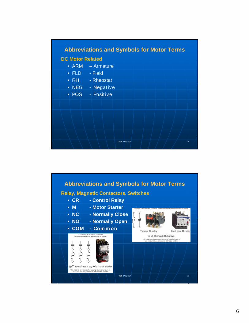
Abbreviations and Symbols for Motor Terms
Relay, Magnetic Contactors, Switches
• CR - Control Relay
• M - Motor Starter
• NC - Normally Close
• NO - Normally Open
• COM - Common
Prof. Paul Lin 12

7
Abbreviations and Symbols for Motor Terms
Electromechanical Relay
• CR - Control Relay
• M - Motor Starter
• NC - Normally Close
• NO - Normally Open
• COM - Common
Prof. Paul Lin 13
Abbreviations and Symbols for Motor Terms
Actuators
Switch Symbols
Prof. Paul Lin 14

8
Abbreviations and Symbols for Motor Terms
Human Machine Interface
• PB - Push Button
• PL - Pilot Light
• NC - Normally Close
• NO - Normally Open
Prof. Paul Lin 15
Abbreviations and Symbols for Motor Terms
Electrical Wires and Connections
Circuit Protection Devices
Prof. Paul Lin 16

9
Motor Control Diagrams and Drawings
A variety of controls diagrams and drawings are used to install, maintain, and troubleshot motor control systems
These diagrams include
• Ladder diagrams – design and simulation
Focuses on the electrical operation and sequence of a motor control circuit
• Block Diagrams
• Wiring diagrams
• Line Diagrams
Prof. Paul Lin 17
Figure 2-3 A Typical Ladder Diagrams
Two vertical rails (L1, L2) – connected to power source
Horizontal lines (rungs) – contain control circuitry
Read: Top => Down; Left to Right
Prof. Paul Lin 18

10
Figure 2-4 Power and Control Circuit Wiring
Control circuit – Control Transformer (480-120 v step down), Fuse, Temp SW, M coil, OL (Over load switch)
Main power circuit – 480v, three-M contacts, OL heating element, Motor
Prof. Paul Lin 19
Figure 2-5 Identification of coils and associated contacts
Control relay: R (coil), CR-1, CR-2 contacts
Magnetic contactors (Starters):• M1 (coil), M1 -| |- NO contact
• M2 (coil), M2 -|\|- NC contact
• M3 (coil), M3 -|\|- NC contact
Prof. Paul Lin 20

11
Figure 2-6 Load and Control Devices Load – a circuit components that has resistance and
consumes electric power• Parallel connection: all load elements receiving the same voltage
Contacts• LS – control => Pilot Light (on/off)
• PB – control => Solenoid (on/off), NC (contact) ontrol => Heater element (on/off)
Prof. Paul Lin 21
Figure 2-7 Load are placed on the right and contacts on the left
Prof. Paul Lin 22
12
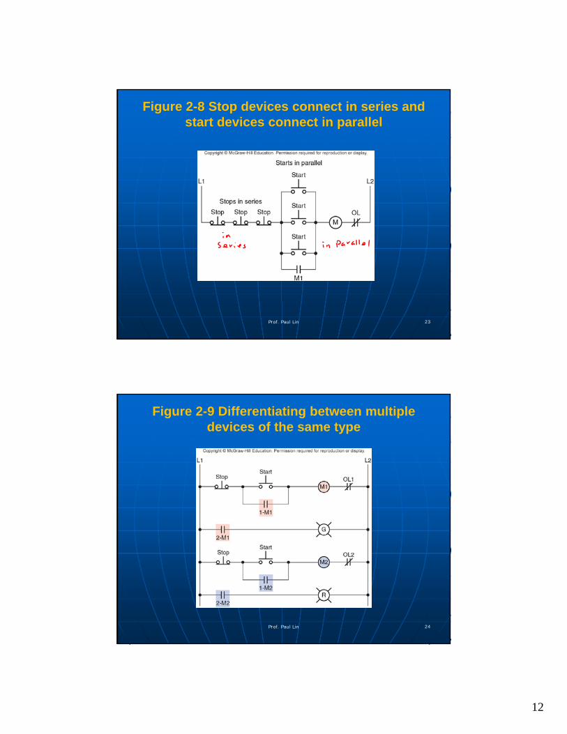
Figure 2-8 Stop devices connect in series and start devices connect in parallel
Prof. Paul Lin 23
Figure 2-9 Differentiating between multiple devices of the same type
Prof. Paul Lin 24
13
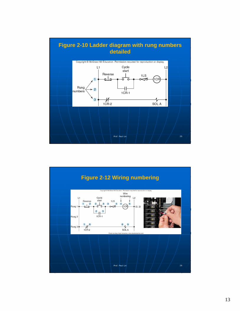
Figure 2-10 Ladder diagram with rung numbers detailed
Prof. Paul Lin 25
Figure 2-12 Wiring numbering
Prof. Paul Lin 26

14
Figure 2-13 Alternative wiring identification with documentation
Prof. Paul Lin 27
Figure 2-14 Representing mechanical functions
Mechanical Interlock
Prof. Paul Lin 28

15
Figure 2-15 Control transformer grounding
(a) control transformer properly grounded to the L2 side of the circuit.
(b) control transformer improperly grounded at the L1 side of the circuit
Prof. Paul Lin 29
Summary & Conclusion
Email: [email protected] or [email protected]
Prof. Paul Lin 30