ece 470 introduction to robotics lab manualcoecsl.ece.illinois.edu/ece470/lab.pdf · ece 470...
TRANSCRIPT
ECE 470Introduction to Robotics
Lab Manual
Dan BlockJonathan K. Holm
Jifei XuYinai Fan
University of Illinois at Urbana-Champaign
Spring 2018

ii

Contents
1 Introduction to the UR3 1
1.1 LAB 1 Week One . . . . . . . . . . . . . . . . . . . . . . . . . 1
1.1.1 Important . . . . . . . . . . . . . . . . . . . . . . . . . 1
1.1.2 Objectives . . . . . . . . . . . . . . . . . . . . . . . . . 1
1.1.3 References . . . . . . . . . . . . . . . . . . . . . . . . . 1
1.1.4 Pre-Lab . . . . . . . . . . . . . . . . . . . . . . . . . . 2
1.1.5 Task . . . . . . . . . . . . . . . . . . . . . . . . . . . . 2
1.1.6 Procedure . . . . . . . . . . . . . . . . . . . . . . . . . 2
1.1.7 Report . . . . . . . . . . . . . . . . . . . . . . . . . . . 4
1.1.8 Demo . . . . . . . . . . . . . . . . . . . . . . . . . . . 4
1.1.9 Grading . . . . . . . . . . . . . . . . . . . . . . . . . . 4
1.2 LAB 1.5 Week Two, The Tower of Hanoi using the TeachPendant . . . . . . . . . . . . . . . . . . . . . . . . . . . . . . 5
1.2.1 Important . . . . . . . . . . . . . . . . . . . . . . . . . 5
1.2.2 Objectives . . . . . . . . . . . . . . . . . . . . . . . . . 5
1.2.3 References . . . . . . . . . . . . . . . . . . . . . . . . . 5
1.2.4 Pre-Lab . . . . . . . . . . . . . . . . . . . . . . . . . . 6
1.2.5 Task . . . . . . . . . . . . . . . . . . . . . . . . . . . . 7
1.2.6 Procedure . . . . . . . . . . . . . . . . . . . . . . . . . 8
1.2.7 Report . . . . . . . . . . . . . . . . . . . . . . . . . . . 8
1.2.8 Grading . . . . . . . . . . . . . . . . . . . . . . . . . . 8
2 The Tower of Hanoi with ROS 11
2.1 Important . . . . . . . . . . . . . . . . . . . . . . . . . . . . . 11
2.2 Objectives . . . . . . . . . . . . . . . . . . . . . . . . . . . . . 11
2.3 Pre-Lab . . . . . . . . . . . . . . . . . . . . . . . . . . . . . . 12
2.4 References . . . . . . . . . . . . . . . . . . . . . . . . . . . . . 12
2.5 Task . . . . . . . . . . . . . . . . . . . . . . . . . . . . . . . . 13
2.6 Procedure . . . . . . . . . . . . . . . . . . . . . . . . . . . . . 14
iii

iv CONTENTS
2.7 Lab2.cpp Explained . . . . . . . . . . . . . . . . . . . . . . . 15
2.8 Report . . . . . . . . . . . . . . . . . . . . . . . . . . . . . . . 23
2.9 Demo . . . . . . . . . . . . . . . . . . . . . . . . . . . . . . . 23
2.10 Grading . . . . . . . . . . . . . . . . . . . . . . . . . . . . . . 24
3 Forward Kinematics 25
3.1 Important . . . . . . . . . . . . . . . . . . . . . . . . . . . . . 25
3.2 Objectives . . . . . . . . . . . . . . . . . . . . . . . . . . . . . 25
3.3 References . . . . . . . . . . . . . . . . . . . . . . . . . . . . . 25
3.4 Tasks . . . . . . . . . . . . . . . . . . . . . . . . . . . . . . . 26
3.4.1 Theoretical Solution . . . . . . . . . . . . . . . . . . . 26
3.4.2 Physical Implementation . . . . . . . . . . . . . . . . . 26
3.4.3 Comparison . . . . . . . . . . . . . . . . . . . . . . . . 26
3.5 Procedure . . . . . . . . . . . . . . . . . . . . . . . . . . . . . 27
3.5.1 Theoretical Solution . . . . . . . . . . . . . . . . . . . 27
3.5.2 Implementation on UR3 . . . . . . . . . . . . . . . . . 27
3.5.3 Comparison . . . . . . . . . . . . . . . . . . . . . . . . 28
3.6 Report . . . . . . . . . . . . . . . . . . . . . . . . . . . . . . . 29
3.7 Demonstration . . . . . . . . . . . . . . . . . . . . . . . . . . 29
3.8 Grading . . . . . . . . . . . . . . . . . . . . . . . . . . . . . . 30
4 Inverse Kinematics 33
4.1 Important . . . . . . . . . . . . . . . . . . . . . . . . . . . . . 33
4.2 Objectives . . . . . . . . . . . . . . . . . . . . . . . . . . . . . 33
4.3 Reference . . . . . . . . . . . . . . . . . . . . . . . . . . . . . 33
4.4 Tasks . . . . . . . . . . . . . . . . . . . . . . . . . . . . . . . 33
4.4.1 Solution Derivation . . . . . . . . . . . . . . . . . . . . 33
4.4.2 Implementation . . . . . . . . . . . . . . . . . . . . . . 36
4.5 Procedure . . . . . . . . . . . . . . . . . . . . . . . . . . . . . 36
4.6 Report . . . . . . . . . . . . . . . . . . . . . . . . . . . . . . . 38
4.7 Demo . . . . . . . . . . . . . . . . . . . . . . . . . . . . . . . 39
4.8 Grading . . . . . . . . . . . . . . . . . . . . . . . . . . . . . . 39
5 Image Processing 41
5.1 Important . . . . . . . . . . . . . . . . . . . . . . . . . . . . . 41
5.2 Objectives . . . . . . . . . . . . . . . . . . . . . . . . . . . . . 41
5.3 References . . . . . . . . . . . . . . . . . . . . . . . . . . . . . 41
5.4 Tasks . . . . . . . . . . . . . . . . . . . . . . . . . . . . . . . 42
5.4.1 Separating Objects from Background . . . . . . . . . . 42
5.4.2 Associating Objects in the Image . . . . . . . . . . . . 42
CONTENTS v
5.5 Procedure . . . . . . . . . . . . . . . . . . . . . . . . . . . . . 42
5.5.1 Separating Objects from Background using the OPENCVfunction adaptiveThreshold() . . . . . . . . . . . . . . 42
5.5.2 Associating Objects in the Image . . . . . . . . . . . . 43
5.6 Report . . . . . . . . . . . . . . . . . . . . . . . . . . . . . . . 49
5.7 Demo . . . . . . . . . . . . . . . . . . . . . . . . . . . . . . . 49
5.8 Grading . . . . . . . . . . . . . . . . . . . . . . . . . . . . . . 49
6 Camera Calibration 51
6.1 Important . . . . . . . . . . . . . . . . . . . . . . . . . . . . . 51
6.2 Objectives . . . . . . . . . . . . . . . . . . . . . . . . . . . . . 51
6.3 References . . . . . . . . . . . . . . . . . . . . . . . . . . . . . 52
6.4 Tasks . . . . . . . . . . . . . . . . . . . . . . . . . . . . . . . 52
6.4.1 Object Centroids . . . . . . . . . . . . . . . . . . . . . 52
6.4.2 Camera Calibration . . . . . . . . . . . . . . . . . . . 52
6.4.3 Pick and Place . . . . . . . . . . . . . . . . . . . . . . 52
6.5 Procedure . . . . . . . . . . . . . . . . . . . . . . . . . . . . . 53
6.5.1 Object Centroids . . . . . . . . . . . . . . . . . . . . . 53
6.5.2 Camera Calibration . . . . . . . . . . . . . . . . . . . 53
6.5.3 Pick and Place . . . . . . . . . . . . . . . . . . . . . . 57
6.6 Report . . . . . . . . . . . . . . . . . . . . . . . . . . . . . . . 57
6.7 Demo . . . . . . . . . . . . . . . . . . . . . . . . . . . . . . . 58
6.8 Grading . . . . . . . . . . . . . . . . . . . . . . . . . . . . . . 58
7 Extra Credit 59
7.1 Objectives . . . . . . . . . . . . . . . . . . . . . . . . . . . . . 59
7.2 References . . . . . . . . . . . . . . . . . . . . . . . . . . . . . 60
7.3 Tasks . . . . . . . . . . . . . . . . . . . . . . . . . . . . . . . 61
7.3.1 ROS . . . . . . . . . . . . . . . . . . . . . . . . . . . . 61
7.3.2 Precision Manipulation . . . . . . . . . . . . . . . . . 61
7.3.3 Computer Vision Algorithms . . . . . . . . . . . . . . 62
7.3.4 Automatic Tower of Hanoi . . . . . . . . . . . . . . . 62
7.4 Procedure . . . . . . . . . . . . . . . . . . . . . . . . . . . . . 62
7.4.1 ROS . . . . . . . . . . . . . . . . . . . . . . . . . . . . 62
7.4.2 Precision Manipulation . . . . . . . . . . . . . . . . . 62
7.4.3 Computer Vision . . . . . . . . . . . . . . . . . . . . . 63
7.4.4 Automatic Tower of Hanoi . . . . . . . . . . . . . . . 63
7.5 Report . . . . . . . . . . . . . . . . . . . . . . . . . . . . . . . 63
7.6 Demo . . . . . . . . . . . . . . . . . . . . . . . . . . . . . . . 63
7.7 Grading . . . . . . . . . . . . . . . . . . . . . . . . . . . . . . 64

vi CONTENTS
A Mathematica and Robotica 67A.1 Mathematica Basics . . . . . . . . . . . . . . . . . . . . . . . 67A.2 Robotica . . . . . . . . . . . . . . . . . . . . . . . . . . . . . . 68A.3 What Must Be Submitted with Robotica Assignments . . . . 69
B C Programming in ROS 71B.1 Overview . . . . . . . . . . . . . . . . . . . . . . . . . . . . . 71B.2 ROS Concepts . . . . . . . . . . . . . . . . . . . . . . . . . . 71B.3 Before we start.. . . . . . . . . . . . . . . . . . . . . . . . . . 72B.4 Create your own workspace . . . . . . . . . . . . . . . . . . . 74B.5 Running A Node . . . . . . . . . . . . . . . . . . . . . . . . . 74B.6 Simple Publisher and Subscriber Tutorial . . . . . . . . . . . 76
C Notes on Computer Vision 77C.1 OpenCV in ROS . . . . . . . . . . . . . . . . . . . . . . . . . 77
C.1.1 Camera Driver . . . . . . . . . . . . . . . . . . . . . . 77C.1.2 Accessing Image Data . . . . . . . . . . . . . . . . . . 78C.1.3 Some Useful OpenCV Functions . . . . . . . . . . . . 80
C.2 Introduction to Pointers . . . . . . . . . . . . . . . . . . . . . 82C.3 Simplifying Camera Calibration . . . . . . . . . . . . . . . . . 83

Preface
This is a set of laboratory assignments designed to complement the introduc-tory robotics lecture taught in the College of Engineering at the Universityof Illinois at Urbana-Champaign. Together, the lecture and labs introducestudents to robot manipulators and computer vision along with the RobotOperating System (ROS) and serve as the foundation for more advancedcourses on robot dynamics, control and computer vision. The course is cross-listed in three departments (Electrical & Computer Engineering, AerospaceEngineering, and Mechanical Science & Engineering) and consequently in-cludes students from a variety of academic backgrounds.
For success in the laboratory, each student should have completed a coursein linear algebra and be comfortable with three-dimensional geometry. Inaddition, it is imperative that all students have completed a freshman-levelcourse in computer programming. Spong, Hutchinson, and Vidyasagar’stextbook Robot Modeling and Control (John Wiley and Sons: New York,2006) is required for the lectures and will be used as a reference for manyof the lab assignments. We will hereafter refer to the textbook as SH&V inthis lab manual.
These laboratories are simultaneously challenging, stimulating, and enjoy-able. It is the author’s hope that you, the reader, share a similar experience.
Enjoy the course!
vii

viii CONTENTS
LAB 1
Introduction to the UR3
1.1 LAB 1 Week One
1.1.1 Important
Read the entire lab before starting and especially the ”Grading” section asthere are points you will receive by completing certain sections or check-points by the end of lab sessions.
1.1.2 Objectives
The purpose of this lab is to familiarize you with the UR3 robot arm andits industrial programming interface called the teach pendant. In this lab,you will:
• learn how to turn on and activate the UR3
• work with the teach pendant to create a simple program for the UR3
• use the teach pendant to turn on and off the suction cup gripper anduse the gripper in a program
• demonstrate a sequence of motions that places one block on top ofanother.
1.1.3 References
• UR3 Owner’s Manual: http://coecsl.ece.illinois.edu/ece470/UR3UserManual-en-US3-4-3.pdf
1
2 LAB 1. INTRODUCTION TO THE UR3
• UR3 Software Manual: http://coecsl.ece.illinois.edu/ece470/SoftwareManual-en-US3-4-3.pdf
• https://www.universal-robots.com/academy/
1.1.4 Pre-Lab
Before you come to lab it is very important that you go through the trainingvideos found at Universal Robots website https://www.universal-robots.com/academy/.These training sessions get into some areas that we will not be using in thisclass (for example you will not be changing safety settings), but go throughall of the assignments as they will help you get familiar with the UR3 andits teach pendant. You also may want to reference these sessions when youare in lab.
1.1.5 Task
Using the teach pendant, each team will “program” the UR3 to pick andplace blocks. The program may do whatever you want, but all programsmust check three predefined locations for two blocks and stack one blockon top of another at a fourth predefined position. You will use the gripper’ssuction feedback to determine if a block is located at one of the three startingblock locations. The blocks must be aligned with each other in the stack oftwo.
1.1.6 Procedure
1. The Pre-Lab asked you to go through the basic UR3 training at Uni-versal Robots website. This training should have shown you how tomake simple programs to move the UR3. Initially your TA will demon-strate how to turn on and enable the UR3 as well as how to use theemergency stop button. Then use this lab time to familiarize yourselfwith the UR3 robot. First play around with simple programs thatmove the robot between a number of points.
2. To turn on the suction for the suction cup gripper, Digital output 0needs to be set high. Set low to turn off the suction. Also digital input0 indicates if the suction cup is gripping something. It will return 1 ifit is gripping an object and 0 if not. Modify your above program (ormake a new one) to add activating on and off the suction cup gripper.

1.1. LAB 1 WEEK ONE 3
3. Create a program that defines four spots on the robot’s table. Threeof these spots are where it is possible a block will be initially locatedand with a certain orientation. There will only be two blocks. Theuser will place the blocks in two of the positions. The goal for therobot is to collect the two blocks and stack them on top of each otherin the fourth define place on the robot’s table. So you will need to usethe suction cup gripper’s feedback that indicates whether an objectis being gripped or not. Then with some “If” instructions completethis task such that the user can put the two blocks in any of the threestarting positions. When you are finished, you will demo your programto your TA showning that your program works when two blocks areplaced and aligned in the three different configurations and also doesnot have a problem if only one block or even no blocks are placed attheir starting positions. Tips for creating this program:
• To turn on the suction cup, use the Set command and selectDigital Output 0 and turn it on or true. Set it to off or false toturn off the suction.
• Digital Input 0 indicates if something has been gripped by thesuction cup. Go to the I/O tab and turn on and off Digital Output0 and check which state of Digital Input 0 indicates gripped andupgripped.
• In the Structure tab under Advanced besides “If ... else”, youmay also want to use the Assignment to create a global workervariable that, for example, stores the number of blocks collected.In addition the SubProg item creates a subroutine that you maycall when performing the same steps. The subroutine’s scopeallows it to see the variables you create with the Assignmentitem.
• You may want to name your Waypoints. This makes your pro-gram easier to read. In addition if the robot needs to go to thesame point multiple times in your program you can command itto go to the same waypoint name.
• Under the Structure tab you can use the Copy and Paste buttonsto copy a line of code and past it in a different subsection of yourcode. This cuts down on extra typing. Also note the Move up anddown buttons along with the Cut and Delete buttons. Suppressis like commenting out a line of code.
• When you add an “If” statement and then click on the Command

4 LAB 1. INTRODUCTION TO THE UR3
tab, tap in the long white box to pull up the keyboard for enteringthe if condition.
4. Demo this working program to your TA. Your TA may ask you toimprove your positioning if the stack does not end up aligned well.
1.1.7 Report
None required. Look at Lab 1 Week Two and Start the longer readingassignment for Lab 2’s pre-lab.
1.1.8 Demo
Show your TA the program you created.
1.1.9 Grading
• 10 points, completing the above tasks by the end of your two hour labsession.
• 90 points, successful demonstration.

1.2. LAB 1.5WEEK TWO, THE TOWEROF HANOI USING THE TEACH PENDANT5
1.2 LAB 1.5 Week Two, The Tower of Hanoi usingthe Teach Pendant
1.2.1 Important
Read the entire lab before starting and especially the ”Grading” section asthere are points you will receive by completing certain sections or check-points by the end of lab sessions.
1.2.2 Objectives
This lab is numbered 1.5 because it continues the programming you learnedin Lab 1 but also prepares you for Lab 2. In Lab 2 and forward you will beusing the Robot Operating System (ROS) structure to program the UR3.For this lab you will continue to program the UR3 using its Teach Pendantbut perform a similar task as will be required in Lab 2, solving a three blockTower of Hanoi puzzle. In this lab, you will:
• move three stacked blocks from one position to another position usingthe rules specified for the Tower of Hanoi puzzle. Blocks should bealigned on top of each other.
• use high level “Move” commands to move the UR3’s Tool Center Pointin linear and circular motions
• time permitting play with other functionality of the teach pendant.
1.2.3 References
• UR3 Owner’s Manual: http://coecsl.ece.illinois.edu/ece470/UR3 User Manual en US3-4-3.pdf
• UR3 Software Manual: http://coecsl.ece.illinois.edu/ece470/Software Manual en US3-4-3.pdf
• https://www.universal-robots.com/academy/
• Since this is a robotics lab and not a course in computer science ordiscrete math, feel free to Google for solutions to the Tower of Hanoiproblem.1 You are NOT required to implement a recursive solution.
1http://www.cut-the-knot.org/recurrence/hanoi.shtml (an active site, as of this writ-ing.)
6 LAB 1. INTRODUCTION TO THE UR3
1.2.4 Pre-Lab
Read in more detail the UR3 Software Manual chapters 13 and 14. Addi-tionally if for some reason you have not completed the training videos, gothrough the training videos found at Universal Robots website https://www.universal-robots.com/academy/. These training sessions get into some areas that wewill not be using in this class (for example you will not be changing safetysettings), but go through all of the assignments as they will help you get fa-miliar with the UR3 and its teach pendant. You also may want to referencethese sessions when you are in lab.

1.2. LAB 1.5WEEK TWO, THE TOWEROF HANOI USING THE TEACH PENDANT7
Figure 1.1: Example start and finish tower locations.
Figure 1.2: Examples of a legal and an illegal move.
1.2.5 Task
The goal is to move a “tower” of three blocks from one of three locationson the table to another. An example is shown in Figure 2.1. The blocksare numbered with block 1 on the top and block 3 on the bottom. Whenmoving the stack, two rules must be obeyed:
1. Blocks may touch the table in only three locations (the three “towers”).
2. You may not place a block on top of a lower-numbered block, as illus-trated in Figure 2.2.

8 LAB 1. INTRODUCTION TO THE UR3
1.2.6 Procedure
1. Choose the three spots on the robot’s table where blocks can be placedwhen solving the Tower of Hanoi problem.
2. Use the provided white stickers to mark the three possible tower bases.You should initial your markers so you can distinguish your tower basesfrom the ones used by teams in other lab sections.
3. Choose a starting position and ending position for the tower of threeblocks. Future note: In Lab 2 the user will enter the start and stoppositions.
4. Using the Teach Pendant create a program that solves the Tower ofHanoi problem. Instead of using MoveJ moves like in Lab 1, exper-iment with using MoveL and MoveP moves. MoveL moves the ToolCenter Point (TCP) along a straight line, and MoveP is a processmove that keeps the TCP moving at a constant speed and allows youto move along circular arcs. Reference these three “How To” articlesfrom Universal Robots on creating circular arcs:
• https://www.universal-robots.com/how-tos-and-faqs/how-to/ur-how-tos/circle-using-movec-16270/
• https://www.universal-robots.com/how-tos-and-faqs/how-to/ur-how-tos/circular-path-using-movepmovec-15668/
• https://www.universal-robots.com/how-tos-and-faqs/how-to/ur-how-tos/circle-with-variable-radius-15367/
5. Your program must have at least one obvious linear move and oneobvious circular move that completely encircles one of the block posi-tions.
1.2.7 Report
Each partner turns in a report. In your own words, explain the teach pen-dant program your group wrote.
1.2.8 Grading
• 10 points, completed this section by the end of the two hour lab session.
• 70 points, successful demonstration.

1.2. LAB 1.5WEEK TWO, THE TOWEROF HANOI USING THE TEACH PENDANT9
• 20 points, report.

10 LAB 1. INTRODUCTION TO THE UR3

LAB 2
The Tower of Hanoi withROS
2.1 Important
Read the entire lab before starting and especially the ”Grading” section asthere are points you will receive by completing certain sections or check-points by the end of lab sessions.
2.2 Objectives
This lab is an introduction to controlling the UR3 robot using the RobotOperating System (ROS) and the C++ programming language. In this lab,you will:
• Record joint angles that position the robot arm at waypoints in theTower of Hanoi solution
• Modify the given starter cpp file to move the robot to waypoints andenable and disable the suction cup gripper such that the blocks aremoved in the correct pattern.
• If the robot suction senses that a block is not in the gripper when itshould be, the program should halt with an error.
• Program the robot to solve the Tower of Hanoi problem allowing theuser to select any of three starting positions and ending positions.
11

12 LAB 2. THE TOWER OF HANOI WITH ROS
2.3 Pre-Lab
Read “A Gentle Introduction to ROS”, available online, Specifically:
• Chapter 2: 2.4 Packages, 2.5 The Master, 2.6 Nodes, 2.7.2 Messagesand message types.
• Chapter 3 Writing ROS programs.
2.4 References
• Consult Appendix B of this lab manual for details of ROS and C++functions used to control the UR3.
• “A Gentle Introduction to ROS”, Chapter 2 and 3. http://coecsl.ece.illinois.edu/ece470/agitr-letter.pdf
• A short tutorial for ROS by Hyongju Park. https://sites.google.com/site/ashortrostutorial/
• http://wiki.ros.org/
• Since this is a robotics lab and not a course in computer science ordiscrete math, feel free to Google for solutions to the Tower of Hanoiproblem.1 You are not required to implement a recursive solution.
1http://www.cut-the-knot.org/recurrence/hanoi.shtml (an active site, as of this writ-ing.)

2.5. TASK 13
Figure 2.1: Example start and finish tower locations.
Figure 2.2: Examples of a legal and an illegal move.
2.5 Task
The goal is to move a “tower” of three blocks from one of three locationson the table to another. An example is shown in Figure 2.1. The blocksare numbered with block 1 on the top and block 3 on the bottom. Whenmoving the stack, two rules must be obeyed:
1. Blocks may touch the table in only three locations (the three “towers”).
2. You may not place a block on top of a lower-numbered block, as illus-trated in Figure 2.2.
For this lab, we will complicate the task slightly. Your cpp program shoulduse the robot to move a tower from any of the three locations to any of theother two locations. Therefore, you should prompt the user to specify thestart and destination locations for the tower.
14 LAB 2. THE TOWER OF HANOI WITH ROS
2.6 Procedure
1. Creat your own workspace as shown in Appendix B.
2. If you haven’t already, download lab2andDriver.tar.gz from thecourse website and extract into your catkin workspace /src folder. Dothis at a command prompt with the tar command, tar -zxvf lab2andDriver.tar.gz.You should see two folders lab2pkg and driver. Compile your workspacewith catkin make. Inside this package you can find lab2.cpp with com-ments to help you complete the lab.
• lab2.cpp a file in src folder with skeleton code to get you startedon this lab. See Appendix B for how to use basic ROS. Also readcarefully through the below section that takes you line by linethrough the starter code.
• CMakeLists.txt a file that sets up the necessary libraries andenvironment for compiling lab2.cpp.
• package.xml This file defines properties about the package in-cluding package dependencies.
• To run lab2 code: In one terminal source it and run roslaunch
ece470 ur3 driver ece470 ur3 driver.launch. IMPORTANT:This .launch file needs to know your robot’s IP address. See Ap-pendix B for finding and setting your robot’s IP. Then open anew termial, source it and run rosrun lab2pkg lab2node
3. Use the provided white stickers or tape to mark the three possibletower bases. You should initial your markers so you can distinguishyour tower bases from the ones used by teams in other lab sections.
4. For each base, place the tower of blocks and use the teach pendant tofind joint angles corresponding to the top, middle, and bottom blockpositions and orientation angles. Record these joint angles for use inyour program.
5. Modify lab2.cpp to prompt the user for the start and destination towerlocations (you may assume that the user will not choose the samelocation twice) and move the blocks accordingly using the suction cupto grip the blocks. The starter file performs basic motions in the mainfunction but provides function definitions for moving the arm andmoving blocks (move arm and move block respectively). Once you

2.7. LAB2.CPP EXPLAINED 15
understand the starter code moving from one position to the next,clean up the code by completing the shell functions move arm andmove block. Move arm moves the tool to a specified location andmove block picks up a block from a tower and can place it on anothertower. You may also create other functions for prompting user inputand solving the tower of Hanoi problem given starting and endinglocations but these are not required.
6. Add one more feature to your program. As you saw in LAB 1.5, theCoval device that is creating the vacuum for the gripper also senses thelevel of suction being produced indicating if an item is in the gripper.Recall that Digital Input 0 and Analog Input 0 are connected to thisfeedback. Use Digital Input 0 or Analog Input 0 to determine if ablock is held by the gripper. If no block is found where a block shouldbe, have your program exit and print an error to the console.To figure out how to do this with ROS you are going to have to doa bit of “ROS” investigation. Use “rostopic list”, “rostopic info” and“rosmsg list” to discover what topic to subscribe and what messagewill be recieved in your subscribe callback function. Once you find thetopic and message run “rosmsg info” to figure out what variable youwill need to read from the message sent to your callback function. Justlike isReady, create a global variable to communicate to your main()code the state of Digital Input 0 or Analog Input 0. Normally onceyou figure out which message you will be using you need to #includethe .h file that defines this message. The include file has already been#include in lab2.h for you. Use the explanation below and the givencode in lab2.cpp that creates the subscription to ur3/position and itscallback function as a guide to subscribe to the rostopic that publishesIO status.
2.7 Lab2.cpp Explained
First open up Lab2.cpp and read through the code and its comments as thisis the latest version of LAB 2’s starter code. Below is the same Lab2.cppfile listing with code comments removed and possible small differences dueto changes in the lab. If you find a difference go with the actual lab2.cpp fileas the correct version. Lab2.cpp is broken down into sections and describedin more detail below.
#include "lab2pkg/lab2.h"

16 LAB 2. THE TOWER OF HANOI WITH ROS
#define PI 3.14159265359
#define SPIN\_RATE 20 /* Hz */
You can find lab2.h in the lab2pkg/include directory. It includes all needed hfiles to allow lab2.cpp to call ROS functionality and standard C++ functions.SPIN RATE will be used as the publish rate to send commands to theECE470 ROS driver.
//arrays defining Waypoints, move arm to these points
double arr1[]={189.87*PI/180,-64.8*PI/180,126.91*PI/180,-150.81*PI/180,-90*PI/180,0*PI/180};
double arr2[]={212.23*PI/180,-45.45*PI/180,97.79*PI/180,-141.65*PI/180,-90*PI/180,0*PI/180};
double arr3[]={118.46*PI/180,-58.32*PI/180,80.58*PI/180,-200.64*PI/180,-90*PI/180,0*PI/180};
double arr4[]={0,0,0,0,0,0};
std::vector<double> Q11 (arr1,arr1+sizeof(arr1) / sizeof(arr1[0]));
std::vector<double> Q12 (arr2,arr2+sizeof(arr2) / sizeof(arr2[0]));
std::vector<double> Q13 (arr3,arr3+sizeof(arr3) / sizeof(arr3[0]));
std::vector<double> v (arr4,arr4+sizeof(arr4) / sizeof(arr4[0]));
This code is initializing four “vector” variables to be used as waypointsand velocity vectors. These variables Q11, Q12, Q13, and v will be usedto command the robot to the six θ’s assigned to the vector. The Q11,Q12 and Q13 vector elements are in radians and arranged in the order{θ1, θ2, θ3, θ4, θ5, θ6, }. The v vector is the final velocity of each joint whenthe waypoint is reached. It makes sense for these velocities to be zero inour case where we want to move from point to point. But if the robotfor example needs to move along a trajecory at constant speed it may bedesirable to have a velocity vector other than zero. We will be keeping thisv vector zero for this class. The assigning of this vector variable is a bitinvolved and confusing so it needs a bit of explaining. First a temporarydouble array is created containing the joint angles for a waypoint. Thenthat temporary array is use to assign the values of the vector. Q11 hastype vector with double elements and it is initialized with a pointer to thebeginning of the array arr1 and a pointer to the end of the array. The codesizeof(arr1)/sizeof(arr1[0]) is the total size of elements of the array arr1divided by the size of an individual arr1 element. So in the case for arr1,it is a 6 element double array. Doubles are 8 bytes so sizeof(arr1) returns48 and sizeof(arr1[0]) returns 8. So the initialization line could be rewrittenstd::vector<double> Q11 (arr1,arr1+6);.
// creating an array of these vectors allows us to iterate through them
// and programatically choose where to go.
std::vector<double> Q [3][3] = { // Q[rows][columns]
{Q11, Q12, Q13},
{Q11, Q12, Q13},
{Q11, Q12, Q13}
};
2.7. LAB2.CPP EXPLAINED 17
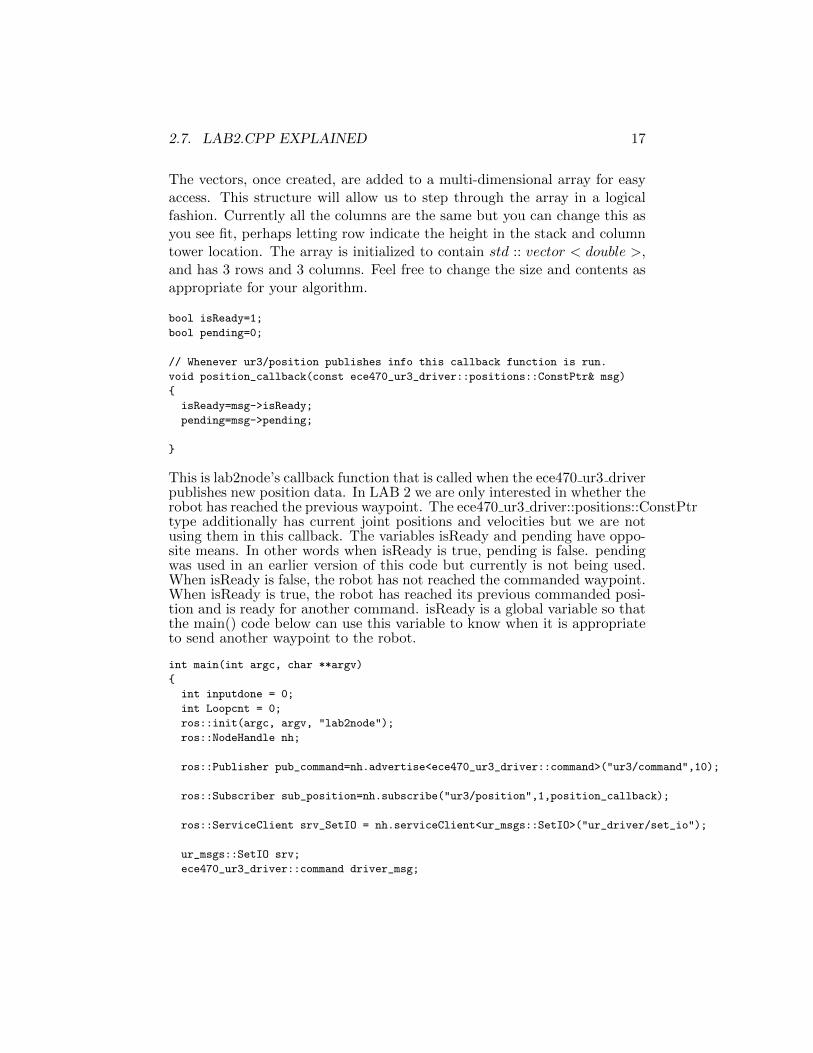
The vectors, once created, are added to a multi-dimensional array for easyaccess. This structure will allow us to step through the array in a logicalfashion. Currently all the columns are the same but you can change this asyou see fit, perhaps letting row indicate the height in the stack and columntower location. The array is initialized to contain std :: vector < double >,and has 3 rows and 3 columns. Feel free to change the size and contents asappropriate for your algorithm.
bool isReady=1;
bool pending=0;
// Whenever ur3/position publishes info this callback function is run.
void position_callback(const ece470_ur3_driver::positions::ConstPtr& msg)
{
isReady=msg->isReady;
pending=msg->pending;
}
This is lab2node’s callback function that is called when the ece470 ur3 driverpublishes new position data. In LAB 2 we are only interested in whether therobot has reached the previous waypoint. The ece470 ur3 driver::positions::ConstPtrtype additionally has current joint positions and velocities but we are notusing them in this callback. The variables isReady and pending have oppo-site means. In other words when isReady is true, pending is false. pendingwas used in an earlier version of this code but currently is not being used.When isReady is false, the robot has not reached the commanded waypoint.When isReady is true, the robot has reached its previous commanded posi-tion and is ready for another command. isReady is a global variable so thatthe main() code below can use this variable to know when it is appropriateto send another waypoint to the robot.
int main(int argc, char **argv)
{
int inputdone = 0;
int Loopcnt = 0;
ros::init(argc, argv, "lab2node");
ros::NodeHandle nh;
ros::Publisher pub_command=nh.advertise<ece470_ur3_driver::command>("ur3/command",10);
ros::Subscriber sub_position=nh.subscribe("ur3/position",1,position_callback);
ros::ServiceClient srv_SetIO = nh.serviceClient<ur_msgs::SetIO>("ur_driver/set_io");
ur_msgs::SetIO srv;
ece470_ur3_driver::command driver_msg;
18 LAB 2. THE TOWER OF HANOI WITH ROS
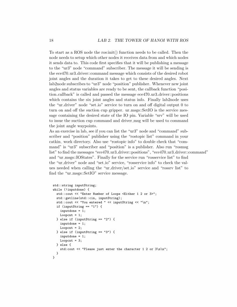
To start as a ROS node the ros:init() function needs to be called. Then thenode needs to setup which other nodes it receives data from and which nodesit sends data to. This code first specifies that it will be publishing a messageto the “ur3” node “command” subscriber. The message it will be sending isthe ece470 ur3 driver::command message which consists of the desired robotjoint angles and the duration it takes to get to these desired angles. Nextlab2node subscribes to “ur3” node “position” publisher. Whenever new jointangles and status variables are ready to be sent, the callback function “posi-tion callback” is called and passed the message ece470 ur3 driver::positionswhich contains the six joint angles and status info. Finally lab2node usesthe “ur driver” node “set io” service to turn on and off digital output 0 toturn on and off the suction cup gripper. ur msgs::SetIO is the service mes-sage containing the desired state of the IO pin. Variable “srv” will be usedto issue the suction cup command and driver msg will be used to commandthe joint angle waypoints.As an exercise in lab, see if you can list the “ur3” node and “command” sub-scriber and “position” publisher using the “rostopic list” command in yourcatkin work directory. Also use “rostopic info” to double check that “com-mand” is “ur3” subscriber and “position” is a publisher. Also run “rosmsglist” to find the messages “ece470 ur3 driver::positions”, “ece470 ur3 driver::command”and “ur msgs::IOStates”. Finally for the service run “rosservice list” to findthe “ur driver” node and “set io” service, “rosservice info” to check the val-ues needed when calling the “ur driver/set io” service and “rossrv list” tofind the “ur msgs::SetIO” service message.
std::string inputString;
while (!inputdone) {
std::cout << "Enter Number of Loops <Either 1 2 or 3>";
std::getline(std::cin, inputString);
std::cout << "You entered " << inputString << "\n";
if (inputString == "1") {
inputdone = 1;
Loopcnt = 1;
} else if (inputString == "2") {
inputdone = 1;
Loopcnt = 2;
} else if (inputString == "3") {
inputdone = 1;
Loopcnt = 3;
} else {
std:cout << "Please just enter the character 1 2 or 3\n\n";
}
}
2.7. LAB2.CPP EXPLAINED 19
This standard C++ code printing messages to the command prompt andrecieving text input from the command prompt. It loops until the correctdata is input.
while(!ros::ok()){};
ROS_INFO("sending Goals");
ros::Rate loop_rate(SPIN_RATE);
int spincount = 0;
Here the code waits for ROScore to be executed and ready. ROS INFOprints a message to the command prompt. ros::Rate loop rate(SPIN RATE)sets up a class loop rate that can be used to sleep the calling process. Theamount of time that the process will sleep is determined by the SPIN RATEparameter. In our case this is set to 20Hz or 50ms. loop rate does not wakeup 50 ms after it has been called, instead it wakes up the process every50ms. loop rate keeps track of the last time it was called to determine howlong to sleep the process to keep a consistent rate.
while(Loopcnt > 0) {
Loopcnt is the number of times to repeat the remaining code. This value isentered by the user.
driver_msg.destination=Q[0][2];
pub_command.publish(driver_msg);
spincount = 0;
while (isReady) {
ros::spinOnce();
loop_rate.sleep();
if (spincount > SPIN_RATE) {
pub_command.publish(driver_msg);
ROS_INFO("Just Published again driver_msg");
spincount = 0;
}
spincount++;
}
ROS_INFO("waiting for rdy");
while(!isReady)
{
ros::spinOnce();
loop_rate.sleep();
}
This block of code publishes a new waypoint, in this case Q3, to the ece470 ur3 driverdriver. But if for some reason the ece470 ur3 driver does not receive the pub-lished command within one second it will publish to the ece470 ur3 driver

20 LAB 2. THE TOWER OF HANOI WITH ROS
again. After the waypoint is published wait until the driver is at the way-point and ready for the next command. Let’s detail each line:
• Set Publisher variable driver msg to new waypoint Q3.
• Publish new waypoint command to ece470 ur3 driver command.
• Loop until isReady is false. isReady turning to false indicates thatece470 ur3 driver has recieved the current command and is movingthe robot to the new waypoint.
• ros::spinOnce is called to allow ROScore to run other ROS processesas needed.
• Put our ROS node to sleep until the next 50ms period is complete.
• If spincount increments to SPIN RATE, 20 in our case, that means onesecond has passed and ece470 ur3 driver has not recived the publishedcommand. republish the same waypoint command.
• Once isReady is false exit the first while loop and enter the secondwhile loop. Sit here now waiting for isReady to be true so that thecode can send another waypoint to the robot if needed.
ROS_INFO("sending Goals 1");
driver_msg.destination=Q[0][0];
pub_command.publish(driver_msg);
spincount = 0;
while (isReady) {
ros::spinOnce();
loop_rate.sleep();
if (spincount > SPIN_RATE) {
pub_command.publish(driver_msg);
ROS_INFO("Just Published again driver_msg");
spincount = 0;
}
spincount++;
}
ROS_INFO("waiting for rdy");
while(!isReady)
{
ros::spinOnce();
loop_rate.sleep();
}
Repeat the same steps to send the waypoint Q[0][0] to the robot arm.

2.7. LAB2.CPP EXPLAINED 21
srv.request.fun = 1;
srv.request.pin = 0;
srv.request.state = 1.0;
if (srv_SetIO.call(srv)) {
ROS_INFO("True: Switched Suction ON");
} else {
ROS_INFO("False");
}
ROS_INFO("Value = %.2f",SuctionValue);
Here the service urmsgs::SetIO is used to turn on the suction cup gripper byturning on digital output 0. srv.request.fun = 1 ? Set the pin to commandto digital out 0. Then set the state of the I/O pin to on by setting state to1.0. Call the service.
ROS_INFO("sending Goals 2");
driver_msg.destination=Q[0][1];
driver_msg.duration=2.0;
pub_command.publish(driver_msg);
spincount = 0;
while (isReady) {
ros::spinOnce();
loop_rate.sleep();
if (spincount > SPIN_RATE) {
pub_command.publish(driver_msg);
ROS_INFO("Just Published again driver_msg");
spincount = 0;
}
spincount++;
}
ROS_INFO("waiting for rdy");
while(!isReady)
{
ros::spinOnce();
loop_rate.sleep();
}
Repeat the same steps to send the waypoint Q[0][1] to the robot arm.
srv.request.fun = 1;
srv.request.pin = 0;
srv.request.state = 0.0;
if (srv_SetIO.call(srv)) {
ROS_INFO("True: Switched Suction OFF");
} else {
ROS_INFO("False");
}

22 LAB 2. THE TOWER OF HANOI WITH ROS
Here the service urmsgs::SetIO is used to turn off the suction cup gripper byturning off digital output 0. srv.request.fun = 1 ? Set the pin to commandto digital out 0. Then set the state of the I/O pin to off by setting state to0.0. Call the service.
ROS_INFO("sending Goals 3");
driver_msg.destination=Q[0][0];
driver_msg.duration=1.0;
pub_command.publish(driver_msg);
spincount = 0;
while (isReady) {
ros::spinOnce();
loop_rate.sleep();
if (spincount > SPIN_RATE) {
pub_command.publish(driver_msg);
ROS_INFO("Just Published again driver_msg");
spincount = 0;
}
spincount++;
}
ROS_INFO("waiting for rdy");
while(!isReady)
{
ros::spinOnce();
loop_rate.sleep();
}
Repeat the same steps to send the waypoint Q[0][0] to the robot arm.
Loopcnt--;
}
return 0;
}
int move_arm(ros::Publisher pub_command , ros::Rate loop_rate, std::vector<double> dest, float duration)
{
int error = 0;
return error;
}
int move_block(ros::Publisher pub_command ,
ros::Rate loop_rate,
ros::ServiceClient srv_SetIO,
ur_msgs::SetIO srv,
int start_loc,
int start_height,
int end_loc,
int end_height)
2.8. REPORT 23
{
int error = 0;
return error;
}
Two function definitions are provided and should be used to complete theassignment. Functions are useful when the same procedure is used manytimes. In the main function, there were several places where the arm wasmoved and this requires about 20 lines of code for each move. The move armfunction takes as its input the ros::Publisher, the ross:Rate, the target des-tination and duration. Its output is an integer that indicates different typesof errors. It is up to the student to decide what the errors may be and howto use them. By replacing each of the blocks of code in the main functionwith a call to move arm, the code is cleaner. In a similar fashion, to move ablock, multiple arm movements are necessary along with gripper actuation.Instead of cluttering the main with many calls to move arm and the gripper,you will compartmentalize the calls in the move block function. In additionto taking ros node information, it also has the service information for in-terfacing with the gripper. Use this function to compartmentalize moving ablock from one tower to another. The start and end locations are integersgiven to tower positions and the heights are integers for blocks in the stack.
2.8 Report
Each partner must submit a hardcopy of your lab2.cpp file with a coversheetcontaining:
• your name in a larger font and your partner’s names in a smaller font.
• “Lab 2”
• the weekday and time your lab section meets (for example, “Monday,1pm”).
• a number of paragraphs explaining in your own words the work youperformed to complete this lab.
2.9 Demo
Your TA will require you to run your program twice; on each run, the TAwill specify a different set of start and destination locations for the tower.

24 LAB 2. THE TOWER OF HANOI WITH ROS
2.10 Grading
• 10 points, by the end of the first two hour lab session, show your TAyour ROS program moving the UR3 to the three Tower of Hanoi stacklocations.
• 10 points, by the end of the second two hour lab session, show yourTA that your ROS program subscribes to the ROS node publishingthe input status of the suction cup gripper.
• 60 points, successful demonstration.
• 20 points, report.

LAB 3
Forward Kinematics
3.1 Important
Read the entire lab before starting and especially the ”Grading” section asthere are points you will receive by completing certain sections or check-points by the end of lab sessions.
3.2 Objectives
The purpose of this lab is to compare the theoretical solution to the forwardkinematics problem with a physical implementation on the UR3 robot. Inthis lab you will:
• parameterize the UR3 following the Denavit-Hartenberg (DH) conven-tion
• use Robotica to compute the forward kinematic equations for the UR3
• write a C++ function that moves the UR3 to a configuration specifiedby the user.
3.3 References
• Chapter 3 of SH&V provides details of the DH convention and itsuse in parameterizing robots and computing the forward kinematicequations.
25

26 LAB 3. FORWARD KINEMATICS
• The complete Robotica function discription manual is available in pdfform on the course website. Additionally, a “crash course” on the useof Robotica and Mathematica is provided in Appendix A of this labmanual.
• If you prefer Matlab Mahmoud KhoshGoftar has shared a set of M-files that translate DH parameters to tranformation matrixes, “De-navit Hartenberg Parameters” by Mahmoud KhoshGoftar.(https://www.mathworks.com/matlabcentral/fileexchange/44585-denavit-hartenberg-parameters)
3.4 Tasks
3.4.1 Theoretical Solution
Find the forward kinematic equations for the UR3 robot using the DanavitHartenburg method. Solve for T 0
6 using Robotica and note the equationsfor the translation vector from the end effector frame to the base frame, d06.
3.4.2 Physical Implementation
The user will provide six joint angles {θ1, θ2, θ3, θ4, θ5, θ6}, all given in de-grees. The angle ranges are as follows:
60 < θ1 < 315
−185 < θ2 < 5
−10 < θ3 < 150
−190 < θ4 < −80
−120 < θ5 < 80
−180 < θ6 < 180
Then using a ROS C++ program move the joints to these desired angles.Your program should additionally calculate and display the translation ma-trix that rotates and translates the end effector’s coordinate frame to thebase frame.
3.4.3 Comparison
For any provided set of joint angles {θ1, θ2, θ3, θ4, θ5, θ6}, roughly comparewith a ruler and square the position of the suction cup gripper to the valuecalculated by your C++ forward kinematics function.

3.5. PROCEDURE 27
3.5 Procedure
3.5.1 Theoretical Solution
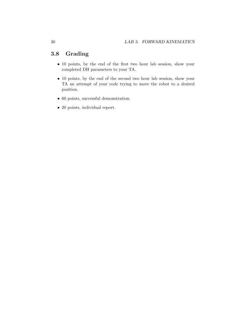
1. Construct a table of DH parameters for the UR3 robot. So it is easierto debug lab issues, use the DH frames already established in Fig-ure 3.1. The dimensions of the UR3 can be found in figure Figure 3.2,except for the suction cup tool offsets. Use a ruler to find the approxi-mate suction cup offsets and then ask your TA to see if you measuredcorrectly.
2. Use Mathematica with the Robotica package to find the translationmatrix using the UR3’s DH parameters. Modify the given exampleMathematica file so that it finds and properly displays the forwardkinematic equation for the UR3. Consult Appendix A of this labmanual for assistance with Mathematica.
3. OR Use matlab “Denavit Hartenberg Parameters” to calculate theforward kinematics. Use simplify() in matlab as you see fit.
3.5.2 Implementation on UR3
1. Download and extract lab3.tar.gz into the “src” directory of yourcatkin directory. Don’t forget “source devel/setup.bash”. Then fromyour base catkin directory run “catkin make” and if you receive no er-rors you copied your lab3 starter code correctly. Also so that ROS reg-isters this new package “lab3pkg”, run “rospack list” and you shouldsee lab3pkg as one of the many packages.
2. One item to note that hopefully does not cause too much confusion.For this LAB 3 and the remaining labs we will be defining θ1 to be180◦ different from what the teach pendant displays. So when youcommand the robot to move to certain joint angles, you will see thatπ has been added the θ1’s value. This change in θ1 makes the DHcoordinate systems more standard.
3. You will notice that in lab3pkg/src that there are now two .cpp files.lab3.cpp is the main() code and lab3func.cpp defines the importantforward kinematic functions. We divide them up in this fashion sothat the forward kinematic functions can easily be used in the remain-ing labs. A library will be compiled that you can include in your nextlabs to call the forward kinematic calculations. In this lab you will
28 LAB 3. FORWARD KINEMATICS
be mainly changing lab3func.cpp. You can of course change lab3.cppbut most of its functionality has already been given to you. Studythe code and comments in lab3.cpp and lab3func.cpp to see what thestarter code is doing and what parts you are going to need to change.Your job is to add the code that correctly populates the six DH ho-mogeneous translation matrixes (DH2HT). The C++ code uses thepackage “eigen” to create and multiply matrixes. The given code sim-ply multiples six identity matrixes. Your job is to change those identitymatrixes to the six DH matrixes for the UR3.
4. Once your code is finished and compiled, run it using “rosrun lab3pkglab3node theta1 theta2 theta3 theta4 theta5 theta6” with all angles indegrees. Remember that in another command prompt you should havefirst ran roscore and other drivers using “roslaunch ece470 ur3 driverece470 ur3 driver.launch”
3.5.3 Comparison
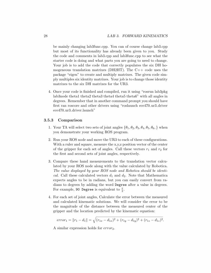
1. Your TA will select two sets of joint angles {θ1, θ2, θ3, θ4, θ5, θ6, } whenyou demonstrate your working ROS program.
2. Run your ROS node and move the UR3 to each of these configurations.With a ruler and square, measure the x,y,z position vector of the centerof the gripper for each set of angles. Call these vectors r1 and r2 forthe first and second sets of joint angles, respectively.
3. Compare these hand measurements to the translation vector calcu-lated by your ROS node along with the value calculated by Robotica.The value displayed by your ROS node and Robotica should be identi-cal. Call these calculated vectors d1 and d2. Note that Mathematicaexpects angles to be in radians, but you can easily convert from ra-dians to degrees by adding the word Degree after a value in degrees.For example, 90 Degree is equivalent to π
2 .
4. For each set of joint angles, Calculate the error between the measuredand calculated kinematic solutions. We will consider the error to bethe magnitude of the distance between the measured center of thegripper and the location predicted by the kinematic equation:
error1 = ‖r1 − d1‖ =√
(r1x − d1x)2 + (r1y − d1y)2 + (r1z − d1z)2.
A similar expression holds for error2.
3.6. REPORT 29
3.6 Report
Each lab partner assemble the following items in the order shown.
1. Coversheet containing your name and then your partner’s names, “Lab3”, and the weekday and time your lab section meets (for example,“Tuesday, 3pm”).
2. A figure of the UR3 robot with DH frames assigned, all joint variablesand link lengths shown, and a complete table of DH parameters.
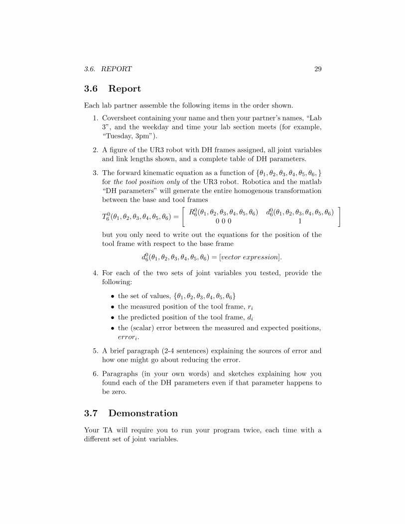
3. The forward kinematic equation as a function of {θ1, θ2, θ3, θ4, θ5, θ6, }for the tool position only of the UR3 robot. Robotica and the matlab“DH parameters” will generate the entire homogenous transformationbetween the base and tool frames
T 06 (θ1, θ2, θ3, θ4, θ5, θ6) =
[R0
6(θ1, θ2, θ3, θ4, θ5, θ6) d06(θ1, θ2, θ3, θ4, θ5, θ6)0 0 0 1
]but you only need to write out the equations for the position of thetool frame with respect to the base frame
d06(θ1, θ2, θ3, θ4, θ5, θ6) = [vector expression].
4. For each of the two sets of joint variables you tested, provide thefollowing:
• the set of values, {θ1, θ2, θ3, θ4, θ5, θ6}• the measured position of the tool frame, ri
• the predicted position of the tool frame, di
• the (scalar) error between the measured and expected positions,errori.
5. A brief paragraph (2-4 sentences) explaining the sources of error andhow one might go about reducing the error.
6. Paragraphs (in your own words) and sketches explaining how youfound each of the DH parameters even if that parameter happens tobe zero.
3.7 Demonstration
Your TA will require you to run your program twice, each time with adifferent set of joint variables.
30 LAB 3. FORWARD KINEMATICS
3.8 Grading
• 10 points, by the end of the first two hour lab session, show yourcompleted DH parameters to your TA.
• 10 points, by the end of the second two hour lab session, show yourTA an attempt of your code trying to move the robot to a desiredposition.
• 60 points, successful demonstration.
• 20 points, individual report.
3.8. GRADING 31
Figure 3.1: UR3 robot with DH frames assigned. Suction Cup GripperAttached.

32 LAB 3. FORWARD KINEMATICS
83
213
2
44
540
83
82
93
120
152
All dimension is in mmFor public use
REV.
TEL: +45 89 93 89 89 FAX: +45 38 79 89 89 WEB: universal-robots.com
DWG NO.
TITLE:
DATE
0100403
Working area UR3 CB3
Status change date:
Figure 3.2: Approximate Dimensions of the UR3 in mm.

LAB 4
Inverse Kinematics
4.1 Important
Read the entire lab before starting and especially the ”Grading” section asthere are points you will receive by completing certain sections or check-points by the end of lab sessions.
4.2 Objectives
The purpose of this lab is to derive and implement a solution to the inversekinematics problem for the UR3 robot. In this lab we will:
• derive elbow-up inverse kinematic equations for the UR3
• write a C++ function that moves the UR3 to a point in space specifiedby the user.
4.3 Reference
Chapter 3 of SH&V provides multiple examples of inverse kinematics solu-tions.
4.4 Tasks
4.4.1 Solution Derivation
Make sure to read through this entire lab before you start into the SolutionDerivation section. There are some needed details not covered in this section.
33

34 LAB 4. INVERSE KINEMATICS
Figure 4.1: Top View Stick Pictorial of UR3. Note that the coordinateframes are in the same direction as the World Frame but not at the Worldframe’s origin. One origin is along the center of joint 1 and the second isalong the center of joint 6.
Given a desired suction cup end effector point in space (xgrip, ygrip, zgrip)and orientation {θyaw, θpitch(fixed), θroll(fixed)}, write six mathematicalexpressions that yield values for each of the joint angles. For the UR3robot, there are many solutions to the inverse kinematics problem. We willimplement only one of the elbow-up solutions.
• In the inverse kinematics problems you have examined in class (for6 DOF arms with spherical wrists), usually the first step is to solvefor the coordinates of the wrist center. The UR3 does not technicallyhave a spherical wrist center but we will define the wrist center as zcenwhich equals the same desired z value of the suction cup and xcen, ycenare the coordinates of θ6’s z axis. In addition, to make the derivationmanageable, add that θ5 will always be −90◦ and θ4 is set such thatlink 5 (DH paramater d5) is always parallel to the world x,y plane.
• Solve the inverse kinematics problem in the following order:
1. xcen, ycen, zcen, given yaw desired in the world frame and thedesired x,y,z of the suction cup. The suction cup aluminum plate

4.4. TASKS 35
Figure 4.2: Side View Stick Pictorial of UR3 without Suction Gripper.
has a length of 0.0535 meters from the center line of the suctioncup to the center line of joint 6. Remember that this aluminumplate should always be parallel to the world’s x,y plane. SeeFigure 4.1.
2. θ1, by drawing a top down picture of the UR3, Figure 4.1, andusing xcen, ycen, zcen that you just calculated. Remember thatlink 5 is always parallel the to table.
3. θ6, which is a function of θ1 and yaw desired. Remember thatwhen θ6 is equal to zero the suction cup aluminum plate is parallelto DH parameter d2.
4. x3end, y3end, z3end is a point off of the UR3 but lies along the z3DH axis, Figure 4.1. For example if θ1 = 0◦ then y3end = 0. Ifθ1 = 90◦ then x3end = 0. First use the top down view of theUR3 to find x3end, y3end. One way is to choose an appropriatecoordinate frame at xcen, ycen and find the translation matrixthat rotates and translates that coordinate frame to the baseframe. Then find the vector in the coordinate frame you choseat xcen, ycen that points from xcen, ycen to x3end, y3end. Simplymultiply this vector by your translation matrix to find the worldcoordinates at x3end, y3end. For z3end create a view of the UR3,

36 LAB 4. INVERSE KINEMATICS
Figure 4.2, that is a projection of the robot onto a plane perpen-dicular to the x,y world frame and rotated by θ1 about the baseframe. Call this the side view. Looking at this side view you willsee that z3end is zcen offset by a constant.
5. θ2, θ3 and θ4, by using the same side view drawing just drawnabove to find z3end, Figure 4.2. Now that x3end, y3end, z3end havebeen found use sine, cosine and the cosine rule to solve for partialangles that make up θ2, θ3 and θ4. Note that in the side viewthe length link 1 is d1, link2 is a2 and link3 is a3. Hint: In thisside view, a parallel to the base construction line through joint2 and a parallel to the base construction line through joint 4 arehelpful in finding the needed partial angles.
4.4.2 Implementation
Implement the inverse kinematics solution by writing a C++ function toreceive world frame coordinates (xWgrip, yWgrip, zWgrip, yawWgrip), computethe desired joint variables {θ1, θ2, θ3, θ4, θ5, θ6}, and command the UR3 tomove to that pose using functions written in LAB3.
4.5 Procedure
• Download lab4.tar.gz from the course website and extract it in your“src” directory. You will notice again that there are two .cpp files.lab4.cpp and lab4func.cpp. The lab4func.cpp file again will be com-piled into a library so that future labs can easily call the inverse kine-matic function. As in LAB 3, most of the needed code is given to youin lab4.cpp. Your main job will be to add all the inverse kinematicequations to lab4funcs.cpp. Note that it will be very helpful to addworker variables in your C code to perform the inverse kinematic cal-culations. If you look at lab4.h it includes lab3.h. This allows you tocall the functions your created in lab3funcs.cpp.
• In your code (This is repeating the derivation steps above):
1. Establish the world coordinate frame (frame w) centered at thecorner of the UR3’s base shown in Figure 4.3. The xw and ywplane should correspond to the surface of the table, with the xwaxis parallel to the sides of the table and the yw axis parallel tothe front and back edges of the table. Axis zw should be normal

4.5. PROCEDURE 37
Figure 4.3: Correct location and orientation of the world frame.
to the table surface, with up being the positive zw direction andthe surface of the table corresponding to zw = 0.We will solve the inverse kinematics problem in the base frame(frame 0), so we will immediately convert the coordinates enteredby the user to base frame coordinates. Write three equationsrelating coordinates (xWgrip, yWgrip, zWgrip) in the world frameto coordinates (xgrip, ygrip, zgrip) in the base frame of the UR3.
xgrip(xWgrip, yWgrip, zWgrip) =
ygrip(xWgrip, yWgrip, zWgrip) =
zgrip(xWgrip, yWgrip, zWgrip) =
Be careful to reference the location of frame 0 as your team de-fined it in LAB 3.
2. Given the desired position of the gripper (xgrip, ygrip, zgrip) (inthe base frame) and the yaw angle, find wrist’s center point(xcen, ycen, zcen).
xcen(xgrip, ygrip, zgrip, yaw) =
ycen(xgrip, ygrip, zgrip, yaw) =
zcen(xgrip, ygrip, zgrip, yaw) =
3. Given the wrist’s center point (xcen, ycen, zcen), write an expres-sion for the waist angle θ1. Make sure to use the atan2() functioninstead of atan() because atan2() takes care of the four quadrantsthe x,y coordinates could be in.
θ1(xcen, ycen, zcen) = (4.1)

38 LAB 4. INVERSE KINEMATICS
4. Solve for the value of θ6, given yaw and θ1.
θ6(θ1, yaw) = (4.2)
5. Find the projected link 3 end point (x3end, y3end, z3end) using(xcen, ycen, zcen) and θ1.
x3end(xcen, ycen, zcen, θ1) =
y3end(xcen, ycen, zcen, θ1) =
z3end(xcen, ycen, zcen, θ1) =
6. Write expressions for θ2, θ3 and θ4 in terms of the link 3 end point.You probably will want to define some intermediate variables tohelp you with these calculations.
θ2(x3end, y3end, z3end) =
θ3(x3end, y3end, z3end) =
θ4(x3end, y3end, z3end) =
7. Now that your code solves for all the joint variables (rememberthat θ5 is always −90◦) send these six values to the LAB3 func-tion lab fk(). Do this simply to check that your inverse kinematiccalculations are correct. Do keep in mind that your forward kine-matic equations calculate the x,y,z position relative to the baseframe not LAB 4’s new world frame. Double check that the x,y,zpoint that you asked the robot to go to is the same value displayedby the forward kinematic equations.
4.6 Report
Each partner assemble the following items in the order shown.
1. Coversheet containing your name and your partner’s names, “Lab 4”,and the weekday and time your lab section meets (for example,“Tuesday, 3pm”).
2. A cleanly written derivation of the inverse kinematics solution foreach joint variable {θ1, θ2, θ3, θ4, θ5, θ6}. The equations and thediagrams can be the same as your partners but the explanationshould be in your own words. You must include figures in yourderivation. Please be kind to your TA and invest the effort to makeyour diagrams clean and easily readable.
4.7. DEMO 39
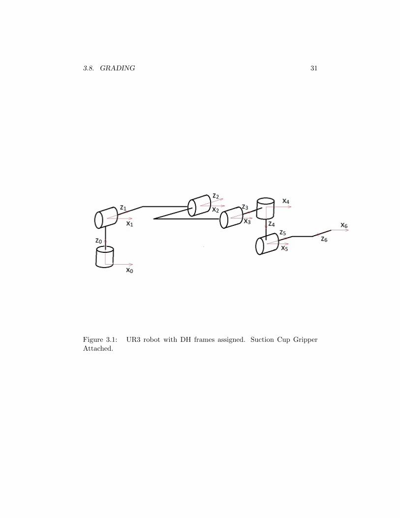
3. For each of the two sets of positions and orientations youdemonstrated, provide the following:
• the set of values {(xWgrip, yWgrip, zWgrip), yaw}• the measured location of the tool
• the (scalar) error between the measured and expected positions.
4. A brief paragraph (2-4 sentences) explaining the sources of error andhow one might go about reducing the error.
5. Print out of your code.
4.7 Demo
Your TA will require you to run your program twice, each time with adifferent set of desired position and orientation. The first demo will requirethe UR3 to reach a point in its workspace off the table. The second demowill require the UR3 to reach a configuration above a block on the tablewith sufficient accuracy to pick up the block.
4.8 Grading
• 10 points, by the end of the first two hour lab session, show your TAyour equations for finding xcen, ycen, zcen.
• 10 points, by the end of the second two hour lab session, show yourTA your equations for {θ1, θ2, θ3, θ4, θ5, θ6}.
• 10 points, by the end of the third two hour lab session, show your TAyour inverse kinematic equations for {θ1, θ2, θ3, θ4, θ5, θ6}implemented in C code.
• 50 points, successful demonstration.
• 20 points, report.

40 LAB 4. INVERSE KINEMATICS

LAB 5
Image Processing
5.1 Important
Read the entire lab before starting and especially the ”Grading” section asthere are points you will receive by completing certain sections orcheckpoints by the end of lab sessions.
5.2 Objectives
This is the first of two labs whose purpose is to integrate computer visionand control of the UR3 robot. In this lab we will:
• separate the objects in a grayscaled image from the background byselecting a threshold greyscale value. This will be done by anauto-thresholding function given in the OPENCV library.
• identify each object with a unique color
• eliminate misidentified objects and noise from image
• determine the number of significant objects in an image.
5.3 References
• Chapter 11 of SH&V provides detailed explanation of the thresholdselection algorithm and summarizes an algorithm for associating theobjects in an image. Please read all of sections 11.3 (theauto-threshold algorithm will be implemented for you) and 11.4before beginning the lab.
41

42 LAB 5. IMAGE PROCESSING
• Appendix C of this lab manual explains how to work with imagedata in your code. Please read all of sections C.1 through C.3 beforebeginning the lab.
5.4 Tasks
5.4.1 Separating Objects from Background
The images provided by the camera are colored, and then converted togray grayscaled. That is, each pixel in the image has an associatedgrayscale value 0-255, where 0 is black and 255 is white. We will assumethat the image can be separated into background (light regions) andobjects (dark regions). We begin by surveying the image and selecting thegrayscale value zt that best distinguishes between objects and thebackground; all pixels with values z > zt (lighter than the threshold) willbe considered to be in the background and all pixels with values z ≤ zt(darker than the threshold) will be considered to be in an object.
The given OPENCV funtion, adaptiveThreshold, will replace each pixel inthe background with a white pixel (z = 255) and each pixel in an objectwith a black pixel (z = 0).
5.4.2 Associating Objects in the Image
Once objects in the image have been separated from the background, wewant to indentify the separate objects in the image. We will distinguishamong the objects by assigning each object a unique color. The pegboardson the workspace will introduce many small “dots” to the image that willbe misinterpreted as objects; we will discard these false objects along withany other noise in the image. Finally, we will report to the user thenumber of significant objects identified in the image.
5.5 Procedure
5.5.1 Separating Objects from Background using theOPENCV function adaptiveThreshold()
1. Read Appendix C in this lab manual before proceeding further.
2. Download the following files from the course website, extract to thesrc folder of your catkin workspace:

5.5. PROCEDURE 43
lab56 . ta r . gz
The cv camera package is the driver of the camera, the lab56 packagecontains the codes for lab 5 and 6. You should go over Appendix Cfor details of the code.
3. Compile the workspace, run the UR3 and camera driver (described inAppendix C).
$ ros launch e c e 4 7 0 u r 3 d r i v e r e c e 4 7 0 l a b 5 6 d r i v e r . launch
Then open another shell (source setup.bash as always) and run lab5’snode:
$ rosrun lab56pkg lab56node
You will see 4 video windows (some could be hidden behind others),and if you left or right click on one of the windows, the position ofthe point you clicked is shown on the shell. You will modify the code“lab56.cpp” so that the 4 windows will show an original coloredimage (already there), a gray scaled image (already there), athresholded image (already there) and an image showing differentobjects with a different color.
4. The auto-thresholding has been done for you by calling the functionadaptiveThreshold() given in the OPENCV library.adaptiveThreshold() finds the best threshold, zt, after consideringeach pixel in the image and colors the pixels white if z > zt, andblack if z ≤ zt. Figure 5.1 shows an image after thresholding.
5.5.2 Associating Objects in the Image
1. Read section 11.4 in SH&V and Appendix C in this lab manualbefore proceeding further.
2. Implement an algorithm that checks 4-connectivity for each pixel andrelates pixels in the same object. The difficult part is noting theequivalence between pixels with different labels in the same object.There are many possible ways to accomplish this task; we outline twopossible solutions here, although you are encouraged to divise yourown clever algorithm.

44 LAB 5. IMAGE PROCESSING
Figure 5.1: Sample image after thresholding.
• A simple but time consuming solution involves performing araster scan for each equivalence. Begin raster scanning theimage until an equivalence is encountered (for example, betweenpixels with label 2 and pixels with label 3). Immediatelyterminate the raster scan and start over again; every time apixel with label 3 is found, relabel the pixel with 2. Continuebeyond the point of the first equivalence until anotherequivalence is encountered. Again, terminate the raster scanand begin again. Repeat this process until a raster scan passesthrough the entire image without noting any equivalencs.
• An alternative approach can associate objects with only tworaster scans. This approach requires the creation of two arrays:one an array of integer labels, the other an array of pointers fornoting equivalences. It should be noted that this algorithm ismemory expensive because it requires two array entries for eachlabel assigned to the image. Consider the following pseudocode.
int label[100];
int *equiv[100];
int pixellabel[height][width];
initialize arrays so that:
equiv[i] = &label[i]
pixellabel[height][width] = -1 if image pixel is white
pixellabel[height][width] = 0 if image pixel is black

5.5. PROCEDURE 45
labelnum = 1;
FIRST raster scan
{
Pixel = pixellabel[row][col]
Left = pixellabel[row][col-1]
Above = pixellabel[row-1][col]
you will need to condition the
assignments of left and above
to handle row 0 and column 0 when
there are no pixels above or left
if Pixel not in background (Pixel is
part of an object)
{
if (Left is background) and
(Above is background)
{
pixellabel[row][col] = labelnum
label[labelnum] = labelnum
labelnum ++
}
if (Left is object) and
(Above is background)
pixellabel[row][col] = Left
if (Left is background) and
(Above is object)
pixellabel[row][col] = Above
EQUIVALENCE CASE:
if (Left is object) and
(Above is object)
{
smallerbaselabel = min{*equiv[Left],
*equiv[Above]}
min = Left if smallerbaselabel==

46 LAB 5. IMAGE PROCESSING
*equiv[Left]
else min = Above
max = the other of {Left, Above}
pixellabel[row][col] =
smallerbaselabel
*equiv[max] = *equiv[min]
equiv[max] = equiv[min]
}
}
}
Now assign same label to all pixels in
the same object
SECOND raster scan
Pixel = pixellabel[row][col]
if Pixel not in background (Pixel is
part of an object)
pixellabel = *equiv[Pixel]

5.5. PROCEDURE 47
For an illustration of how the labels in an image change afterthe first and second raster scans, see Figure 5.2. Figure 5.3shows how equivalence relations affect the two arrays andchange labels during the first raster scan.
Figure 5.2: Pixels in the image after thresholding, after the first rasterscan, and after the second raster scan. In the first image, there are onlyblack and white pixels; no labels have been assigned. After the first rasterscan, we can see the labels on the object pixels; an equivalence is noted bysmall asterisks beside a label. After the second raster scan, all the pixels inthe object bear the same label.
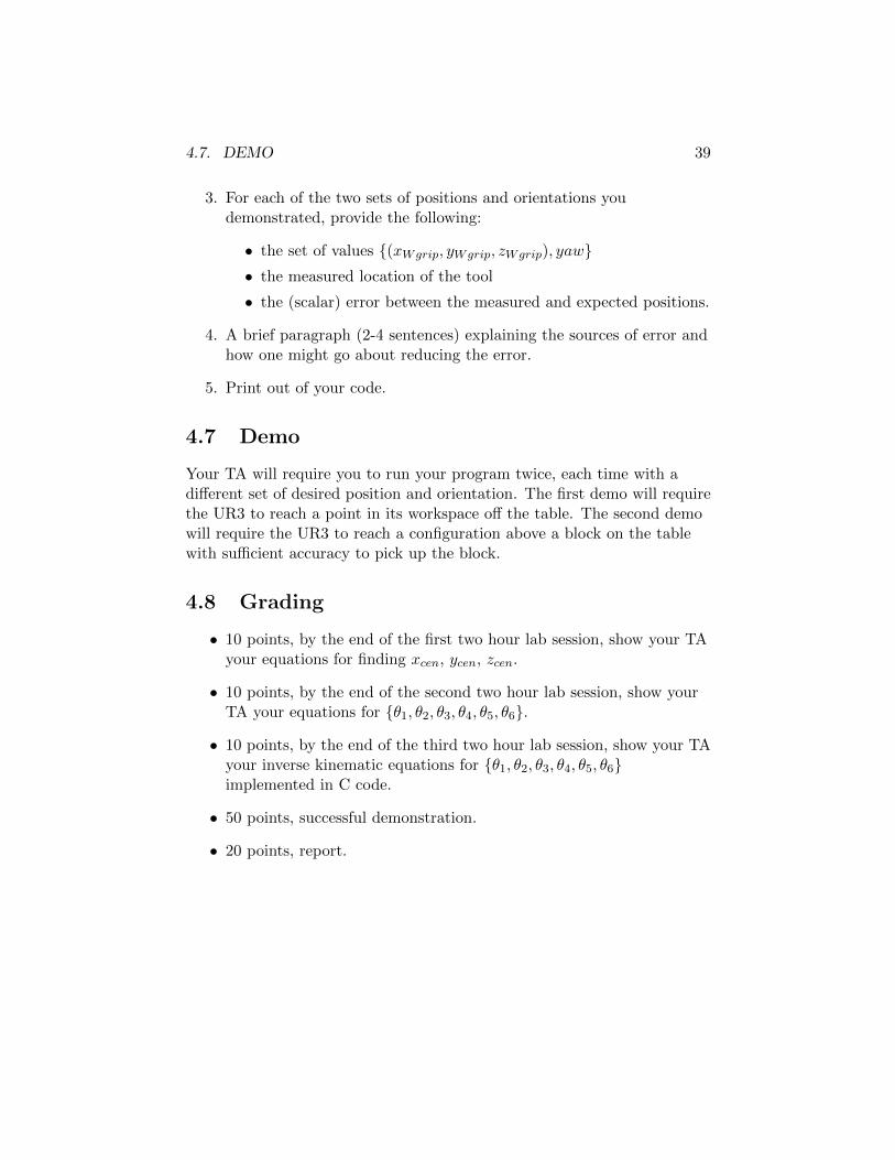
3. Once all objects have been identified with unique labels for eachpixel, we next perform “noise elimination” and discard the smallobjects corresponding to holes in the tabletop or artifacts fromsegmentation. To do this, compute the number of pixels in eachobject. We could again implement a within-group variance algorithmto automatically determine the threshold number of pixels thatdistinguishes legitimate objects from noise objects, but you maysimply choose a threshold pixel count yourself. For the objects whosepixel count is below the threshold, change the object color to white,thereby forcing the object into the background. Figure 5.4 providesan example of an image after complete object association and noiseelimination.
4. Report to the user the number of legitimate objects in the image.

48 LAB 5. IMAGE PROCESSING
Figure 5.3: Evolution of the pixel labels as equivalences are encountered.
5.6. REPORT 49
Figure 5.4: Sample image after object association.
5.6 Report
As a group, submit your lab56.cpp file by emailing it as an attachment toyour TA. First, rename the file with the last names of your groupmembers. For example, if Barney Rubble and Fred Flintstone are in yourgroup, you will submit RubbleFlintstone5.cpp. Make the subject of youremail “Lab 5 Code.” Individually, write a number of paragraphsexplaining your associating objects algorithm from section 5.5.2. It mayhelp to intermix your source code with this explanation.
5.7 Demo
You will demonstrate your working solution to your TA with variouscombinations of blocks and other objects.
5.8 Grading
• 10 points, by the end of the first two hour lab session, demonstrateto your TA you completed section 5.5.1.
• 10 points, by the end of the second two hour lab session, demonstrateto your TA a reasonable attempt to finish the work of section 5.5.2.
• 60 point, successful demonstratoin.

50 LAB 5. IMAGE PROCESSING
• 20 points, report.
LAB 6
Camera Calibration
6.1 Important
Read the entire lab before starting and especially the ”Grading” section asthere are points you will receive by completing certain sections orcheckpoints by the end of lab sessions.
6.2 Objectives
This is the capstone lab of the semester and will integrate your work donein labs 3-5 with forward and inverse kinematics and computer vision. Inthis lab you will:
• find the image centroid of each object and draw crosshairs over thecentroids
• develop equations that relate pixels in the image to coordinates inthe world frame
• report the world frame coordinates (xw, yw) of the centroid of eachobject in the image
• Using the prewritten point-and-click functions, command the robotto retrieve a block placed in veiw of the camera and move it to adesired location.
51

52 LAB 6. CAMERA CALIBRATION
6.3 References
• Chapter 11 of SH&V explains the general problem of cameracalibration and provides the necessary equations for finding objectcentroids. Please read all of sections 11.1, 11.2, and 11.5 beforebeginning the lab.
• Appendix C of this lab manual explains how to simplify the intrinsicand extrinsic equations for the camera. Please read before beginningthe lab.
6.4 Tasks
6.4.1 Object Centroids
In lab 5, we separated the background of the image from the significantobjects in the image. Once each object in the image has been distinguishedfrom the others with a unique label, it is a straightforward task toindentify the pixel corresponding to the centroid of each object.
6.4.2 Camera Calibration
The problem of camera calibration is that of relating (row,column)coordinates in an image to the corresponding coordinates in the worldframe (xw, yw, zw). Chapter 11 in SH&V presents the general equations foraccomplishing this task. For our purposes we may make severalassumptions that will vastly simplify camera calibration. Please consultsection C.3 in this lab manual and follow along with the simplification ofthe general equations presented in the textbook.
Several parameters must be specified in order to implement the equations.Specifically, we are interested in θ the rotation between the world frameand the camera frame and β the scaling constant between distances in theworld frame and distances in the image. We will compute these parametersby measuring object coordinates in the world frame and relating them totheir corresponding coordinates in the image.
6.4.3 Pick and Place
The final task of this lab integrates the code you have written for labs 3-5.Your LAB 5 code provides the processed image from which you have now

6.5. PROCEDURE 53
generated the world coordinates of each object’s centroid. We can relatethe unique color of each object (which you assigned in LAB 5) with thecoordinates of the object’s centroid. Using the prewritten point-and-clickfunctions, you may click on an object in an image and feed the centroidcoordinates to your LAB 4 inverse kinematics function. Recall that theLAB4 function lab invk() given the desired x,y,z world position returns theneeded joint angles. Publish these joint angles to the ur3/command topic.
You will bring together your LAB 3-5 code and the prewrittenpoint-and-click functions in the following way:
• the user will left click on a block in the image console,
• your code will command the UR3 to move to a pose above that block,
• command the UR3 to grip the block’
• return to the home position with the block in its grip,
• the user will click on an unoccupied portion of the image,
• the UR3 will move to the corresponding region of the table andrelease the block.
6.5 Procedure
6.5.1 Object Centroids
1. Read section 11.5 in SH&V before proceeding further.
2. Edit the associateObjects function you wrote for lab 5. Implementthe centroid computation equations from SH&V by adding code thatwill identify the centroid of each significant object in the image.
3. Display the row and column of each object’s centroid to the user.
4. Draw crosshairs in the image over each centroid.
6.5.2 Camera Calibration
1. Read sections 11.1 and 11.2 in SH&V and section C.3 in this labmanual before proceeding further. Notice that, due to the way rowand column are defined in our image, the camera frame is oriented in
54 LAB 6. CAMERA CALIBRATION
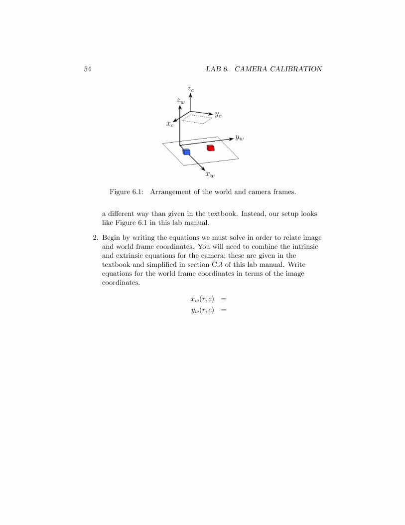
Figure 6.1: Arrangement of the world and camera frames.
a different way than given in the textbook. Instead, our setup lookslike Figure 6.1 in this lab manual.
2. Begin by writing the equations we must solve in order to relate imageand world frame coordinates. You will need to combine the intrinsicand extrinsic equations for the camera; these are given in thetextbook and simplified in section C.3 of this lab manual. Writeequations for the world frame coordinates in terms of the imagecoordinates.
xw(r, c) =
yw(r, c) =
6.5. PROCEDURE 55
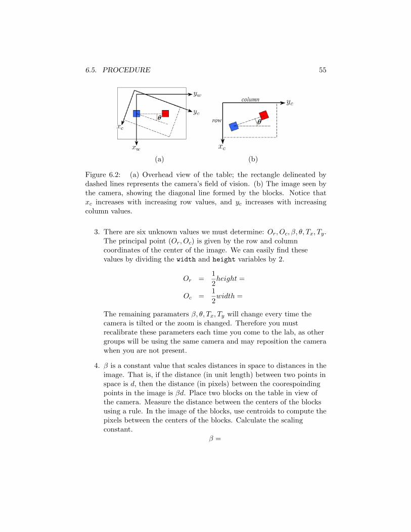
(a) (b)
Figure 6.2: (a) Overhead view of the table; the rectangle delineated bydashed lines represents the camera’s field of vision. (b) The image seen bythe camera, showing the diagonal line formed by the blocks. Notice thatxc increases with increasing row values, and yc increases with increasingcolumn values.
3. There are six unknown values we must determine: Or, Oc, β, θ, Tx, Ty.The principal point (Or, Oc) is given by the row and columncoordinates of the center of the image. We can easily find thesevalues by dividing the width and height variables by 2.
Or =1
2height =
Oc =1
2width =
The remaining paramaters β, θ, Tx, Ty will change every time thecamera is tilted or the zoom is changed. Therefore you mustrecalibrate these parameters each time you come to the lab, as othergroups will be using the same camera and may reposition the camerawhen you are not present.
4. β is a constant value that scales distances in space to distances in theimage. That is, if the distance (in unit length) between two points inspace is d, then the distance (in pixels) between the coorespoindingpoints in the image is βd. Place two blocks on the table in view ofthe camera. Measure the distance between the centers of the blocksusing a rule. In the image of the blocks, use centroids to compute thepixels between the centers of the blocks. Calculate the scalingconstant.
β =

56 LAB 6. CAMERA CALIBRATION
5. θ is the angle of rotation between the world frame and the cameraframe. Please refer to section C.3 of this lab manual for anexplanation of why we need only one angle to define this rotationinstead of two as described in the textbook. Calculating this angleisn’t difficult, but it is sometimes difficult to visualize. Place twoblocks on the table in view of the camera and arranged in a lineparallel to the world y axis as shown in Figure 6.1. Figure 6.2 givesan overhead view of the blocks with a hypothetical cutoutrepresenting the image captured by the camera. Because thecamera’s x and y axes are not quite parallel to the world x and yaxes, the blocks appear in a diagonal line in the image. Using thecentroids of the two blocks and simple trigonometric fuctions,compute the angle of this diagonal line and use it to find θ, the angleof rotation between the world and camera frames.
θ =
6.6. REPORT 57
6. The final values remaining for calibration are Tx, Ty, the coordinatesof the origin of the world frame expressed in the camera frame. Tofind these values, measure the world frame coordinates of the centersof two blocks; also record the centroid locations produced by yourcode. Substitute these values into the two equations you derived instep 2 above and solve for the unknown values.
Tx =
Ty =
7. Finally, insert the completed equations in your lab56.cpp file in theonMouse() function. Your code should report to the user thecentroid location of each object in the image in (row,column) andworld coordinates (xw, yw).
6.5.3 Pick and Place
When the user clicks inside an image, the row and column position of themouse is passed into the “onMouse” function in lab56.cpp.
1. The OnMouse function should enable you to left click onto one of theblocks on the screen and then tell the robot to grip the block andreturn to an intermediate position. Inside the OnMouse callbackfunction first convert the pixel coordinate to world coordinates. Thenpass this coordinate to LAB4’s lab invk() function. lab invk()returns the need joint angles. Publish these joint angles to theur3/command topic. Finally move the robot to an intermediate pointwaiting for a right click. After you get this working well you maywant to add a few other points in robot’s movement so that itdoesn’t hit other possible blocks in the robot’s work space.
2. On a right click, move the block to the right clicked position andrelease the block. Return to a start position that you choose.
6.6 Report
As a group, submit your lab56.cpp file by emailing it as an attachment toyour TA. First, rename the file with the last names of your groupmembers. For example, if Barney Rubble and Fred Flintstone are in yourgroup, you will submit RubbleFlintstone6.cpp. Make the subject of your

58 LAB 6. CAMERA CALIBRATION
email “Lab 6 Code.” Individually wirte a number of paragraphsexplaining the algorithm you implemented to calibrate the cameracoordinate frame into the UR3’s world frame in section 6.5.2.
6.7 Demo
You will demonstrate to your TA your code which draws crosshairs over thecentroid of each object in an image and reports the centroid coordinates in(row,column) and (x, y)w coordinates. For the pick and place task, you willalso demonstrate that the robot will retrieve a block after you left click onit in the image. The robot must also place the block in another locationwhen you right click on a separate position in the image.
6.8 Grading
• 10 points, by the end of the first two hour lab session, show your TAthat you have finished section 6.5.1 and have started work on section6.5.2.
• 10 points, by the end of the second two hour lab session, show yourTA that you have finished section 6.5.2 and have made good progresson section 6.5.3.
• 60 points, successful demonstration.
• 20 points, report.

LAB 7
Extra Credit
7.1 Objectives
In Lab 6, you combined the work of all the previous labs to perform asimple computer vision task. The demonstration in lab 6 is notparticularly useful on its own but can be thought of as a proof of conceptor motion primitive for a more complex application.For extra credit you may choose to complete any of the followingobjectives.Do not let your work on these projects interfere with thecompletion of your regularly scheduled lab work either in timemanagement or corrupting code. Furthermore, the maximumgrade you can receive from doing extra credit in the lab class is100%.
1. ROS: ROS is a powerful set of software libraries and is easy to useonce it has been set up. For this task you are required to create asingle package which combines all the functionality of the previouslab assignments.
2. Precision Manipulation In lab 6 you created a function thatconverted pixel coordinates to world coordinates. However this onlyworked in a single plane. Extend this function to work for blocksplaced at any height and anywhere in the image. You may promptthe user for the height of the block.
3. Computer Vision Algorithms: Measure and label each stack ofblocks in the image with its height using nothing but the image onthe screen.
59
60 LAB 7. EXTRA CREDIT
4. Automatic Tower of Hanoi: Combine parts 2 and 3 to recursivelyplay the Tower of Hanoi game with the tallest stack of blocks in theimage.
7.2 References
1. ROS:
• Look at the package files ”CMakeLists.txt” and ”package.xml”in lab 3 for an example.
• Packages:http://wiki.ros.org/ROS/Tutorials/CreatingPackage
• CMakeLists: http://wiki.ros.org/catkin/CMakeLists.txt
2. Precision Manipulation
• Chapter 11 of SH&V explains the general problem of cameracalibration and one method of finding the camera parameters.
• Both OpenCV and Mathworks have methods for generating thecamera parameter and rotation matrices you need to describethe position of the camera in terms of world coordinates. Feelfree to use either.
– OpenCV documentation: Camera Calibration and 3DReconstruction.
– Mathworks https://www.mathworks.com/help/vision/
ug/single-camera-calibrator-app.html
• A calibration checkerboard can be found at:http://wiki.ros.org/camera_calibration/Tutorials/
MonocularCalibration?action=AttachFile&do=view&
target=check-108.pdf
3. Computer Vision Algorithms:
4. Automatic Tower of Hanoi:
• The recursive Tower of Hanoi solution can be found athttp://www.cut-the-knot.org/recurrence/hanoi.shtml .
7.3. TASKS 61
7.3 Tasks
7.3.1 ROS
For this assignment you will be creating your own ROS package using theroscreate-pkg command. In the previous labs, each ROS package was aassociated with a single node, e.g. lab3pkg lab3node. For this assignmentyou will be creating a new package that depends only on the driverspackage given to you and not on any of the lab assignment packages.Expected Hierarchy:
• ece470pkg
– gohome - move arm into home position.
– goaway - move arm out of image frame.
– gostandby - move arm into predefined standby position awayfrom table.
– movej - move to joint angles with angles given in degrees asarguments.
– movel - move tool tip to rectilinear location x y z yaw in worldcoordinates.
– locate - returns current joint angles, tool location in both robotbase and world frame.
– camera view - displays current camera image.
– camera process - displays all the processed image windowsrequired for lab 5.
– camera move - move the arm to position of click in imagewindow.
– hanoi - prompt user for input and executes Tower of Hanoiprogram.
Because the functionality used in these nodes is shared, you will berequired to create at least one library file like lab3func.cpp which containsall the functions your nodes will need (you may have more library files ifyou prefer).
7.3.2 Precision Manipulation
Much like lab 6 you are being asked to click on a point in the cameraimage and have the arm go to that location. However this is now a three

62 LAB 7. EXTRA CREDIT
dimensional problem and accuracy is required throughout the image. Youwill be given a stack of blocks placed randomly in the image and when theuser clicks on the stack, the program should prompt the user for the heightof the blocks. With this information the suction cup should move directlyover the top of the stack.
7.3.3 Computer Vision Algorithms
In lab 5 you were asked to implement an image processing algorithm whichclassified objects and determined their centroid. For this assignment youwill need to design and implement an algorithm to determine the height ofa stack of blocks from the image.To determine the height, you will need to identify some feature of the stackwhich is known and varies with height. For example, we know the width ofthe block and as it gets closer to the camera it will look larger. From thisinformation we can solve for the height.
7.3.4 Automatic Tower of Hanoi
The goal of this assignment is to move a stack of blocks, with arbitraryheight and location, to a preset final location without violating the rules ofthe Tower of Hanoi game. Full credit is awarded for fully automaticcompletion of the game, while user input for location and height of thestack will result in partial credit.
7.4 Procedure
Since this is an extra credit assignment, no procedure is given. There aresome hints about how you may wish to proceed but you are not bound tofollow them if you can complete the requirements in some other fashion.
7.4.1 ROS
Don’t try and do all of this at once. Lab 3 provide a good example of howto handle libraries and node creation. Start with a single node (maybe thelocate node) and then add the other nodes one at a time.
7.4.2 Precision Manipulation
Use Matlab’s cameracalibrator command to find the camera calibrationand rotation matrices to go from image to world frame and subtract an

7.5. REPORT 63
offset to based on where your world origin is located. Then use theknowledge of the camera height and the height of the block stack todetermine where the arm should go based on the distance of the stack fromthe image center.
7.4.3 Computer Vision
The top plane of this block is the only feature that you can see when thetower is directly under the camera so it may be the feature you try andidentify. You may also be able to use some knowledge of how the centroidis located in a tower to estimate the height of the blocks.For the demonstration, you are allowed to choose the color of your topblock. Use this to help you consistently identify block features.
7.4.4 Automatic Tower of Hanoi
This assignment relies on several of the other parts and even if the fullproject is out of reach the partial completion will still get you some points.
7.5 Report
No report is necessary but you must submit your code by emailing it as anattachment to your TA using the same naming convention as the previouslabs.
7.6 Demo
ROS:
• Show successful compilation of the ece470pkg.
• Show node definitions, dependencies and include files for all functionlibraries and nodes.
• Show that motion nodes move to the correct locations.
• Show that the camera nodes produce the correct images and can beused to move the robot.
Precision Manipulation:
64 LAB 7. EXTRA CREDIT
• Block stacks of heights between 1 and 6 blocks will be placed in allfour quadrants (relative to world origin) of the camera image. Yourprogram should be able to place the tool tip above the top blockwhen you click on the top of the stack and input the height of thestack.
Computer Vision:
• Block stacks with heights between 1 and 6 blocks will be placed inthe camera image. When you click on the stacks in the image, theheight in blocks should be displayed.
• Since computer vision can be tricky, students may use whatever colorblock they wish for the top of the stack.
Automatic Tower of Hanoi:
• A source tower of 3-6 blocks will be placed somewhere in the cameraimage. You must have it move the stack to a predefined destinationlocation without violating the game rules. Full credit is awarded if nouser input is required. Partial credit is awarded if the stack locationand height need to be provided.
7.7 Grading
Each of the assignments is worth 1 bonus point and a total of 4 points canbe earned for the completion of all extra assignments. Please note that themaximum grade you can receive for the entire lab course 100%. Extracredit above 100% does not apply.
1. ROS:
• 12.5 points out of 100 - successful demonstration of all motionnodes.
• 12.5 points out of 100 - successful demonstration of all camerabased nodes.
2. Precision Manipulation:
• 12.5 points out of 100 - suction cup above block for 3/4 of imagespace, some errors allowed.
• 12.5 points out of 100 - suction cup in center of block for entirework area.

7.7. GRADING 65
3. Computer Vision:
• 12.5 points out of 100 - Successfully identify known feature thatvaries with height. Show the geometry and explain that youhave all the parameters necessary to solve for the height of thestack.
• 12.5 points out of 100 - Successfully estimate block height fromimage.
4. Automatic Tower of Hanoi:
• 12.5 points out of 100 - Recursively solve arbitrary Tower ofHanoi with user input of source stack height and source locationvia mouse click.
• 12.5 points out of 100 - Recursively solve Tower of Hanoi basedonly on image data.

66 LAB 7. EXTRA CREDIT

Appendix A
Mathematica and Robotica
A.1 Mathematica Basics
• To execute a cell press <Shift>+<Enter> on the keyboard or<Enter> on the numberic keypad. Pressing the keyboard <Enter>will simply move you to a new line in the same cell. In addition youcan select the ”Evaluation–Evaluate Notebook” menu item and allyour cells will be evaluated.
• Define a matrix using curly braces around each row, commasbetween each entry, commas between each row, and curly bracesaround the entire matrix. For example:
M = {{1, 7}, {13, 5}}
• To display a matrix use MatrixForm which organizes the elements inrows and columns. If you constructed matrix M as in the previousexample, entering MatrixForm[M] would generate the followingoutput: (
1 713 5
)If your matrix is too big to be shown on one screen, Mathematicaand Robotica have commands that can help (see the final section ofthis document).
• To multiply matrices do not use the asterisk. Mathematica uses thedecimal for matrix multiplication. For example, T=A1.A2 multipliesmatrices A1 and A2 together and stores them as matrix T.
67
68 APPENDIX A. MATHEMATICA AND ROBOTICA
• Notice that Mathematica commands use square brackets and arecase-sensitive. Typically, the first letter of each word in a commandis capitalized, as in MatrixForm[M].
• Trigonometric functions in Mathematica operate in radians. It ishelpful to know that π is represented by the constant Pi (Capital ‘P’,lowercase ‘i’). You can convert easily from a value in degrees to avalue in radians by using the command Degree. For example, writing90 Degree is the same as writing Pi/2.
A.2 Robotica
• Robotica was written here at the University of Illinois in 1993 byJohn Nethery and M.W.Spong. In 2016 Mohammad Sultan andAaron T. Becker from the University of Houston completelyrefreshed and enhanced Robotica and have given it the version 4.0.The easiest way to use Robotica is just by example. The below stepsare going to have you check out Robotica and run the given example.Then you simply need to modify the example with the DHparameters for the UR3. NOTE: Robotica displays a stick figure ofthe manipulator associated with your DH parameters. To make thestick figure look reasonable for the UR3 use units of decimetersinstead of meters or millimeters.
• Download robotica.zip from the lab websitehttp://coecsl.ece.illinois.edu/ece470/ to a directory to where youwould like to store your Robotica files.
• Double click on the robotica V4 example.nb example file to loadMathematica. Once loaded you will see that this example is using arobot configuration that has a prismatic joint and two revolutejoints. If the stick figure robot picture is not displayed select theEvaluation–Evaluate Notebook menu item to run the notebook.
• Modify the ”ex” matrix, which is a matrix of all the DH parameters,for the UR3. The matrix is made up of five rows. Row 1 is specifyingif the movable joint is prismatic ’p’ or revolute ’r’. Row 2 DHparamter ’a’ (called ’r’ here in Robotica V4.0). Row 3 DH parameter’α’. Row 4 DH parameter ’d’. Row 5 DH parameter ’θ’. Note thatthe variables are called q1,q2,.... REMEMBER to use units ofdecimeters for the UR3.

A.3. WHATMUST BE SUBMITTEDWITH ROBOTICA ASSIGNMENTS69
• Change the dimensions of the A and T matrixes being printed to 6thorder instead of 3rd order.
• Once you have the UR3 DH parameters entered run the menucommand Evaluation–Evaluate Notebook and after a few seconds theUR3 stick figure should be displayed.
• Now you can use the given controls to move around the animation ofthe UR3. Note the equations for the T 0
6 . Also note in the firstpicture of the robot the H matrix (T 0
6 ) is calculated for the thetasthat were set by the given sliders.
A.3 What Must Be Submitted with RoboticaAssignments
For homework and lab assignments requiring Robotica, you must submiteach of the following:
1. figure of the robot clearly showing DH frames and appropriate DHparameters
2. table of DH parameters
3. matrices relevant to the assignment or application, simplified asmuch as possible and displayed in MatrixForm.
Do not submit the entire hardcopy of your Mathematica file. Rather, cutthe relevant matrices from your print out and paste them onto yourassignment.

70 APPENDIX A. MATHEMATICA AND ROBOTICA

Appendix B
C Programming in ROS
B.1 Overview
ROS is an open-source, meta-operating system for your robot. It providesthe services you would expect from an operating system, includinghardware abstraction, low-level device control, implementation ofcommonly-used functionality, message-passing between processes, andpackage management. It also provides tools and libraries for obtaining,building, writing, and running code across multiple computers.
• The ROS runtime ”graph” is a peer-to-peer network of processes(potentially distributed across machines) that are loosely coupledusing the ROS communication infrastructure. ROS implementsseveral different styles of communication, including synchronousRPC-style communication over services, asynchronous streaming ofdata over topics, and storage of data on a Parameter Server.
• For more details about ROS: http://wiki.ros.org/
• How to install on your own Ubuntu:http://wiki.ros.org/ROS/Installation
• For detailed tutorials: http://wiki.ros.org/ROS/Tutorials
B.2 ROS Concepts
The basic concepts of ROS are nodes, Master, messages, topics, ParameterServer, services, and bags. However, in this course, we will only beencountering the first four.
71

72 APPENDIX B. C PROGRAMMING IN ROS
• Nodes programs or processes in ROS that perform computation. Forexample, one node controls a laser range-finder, one node controls hewheel motors, one node performs localization ...
• Master Enable nodes to locate one another, provides parameterserver, tracks publishers and subscribers to topics, services. In orderto start ROS, open a terminal and type:
$ r o s c o r e
roscore can also be started automatically when using roslaunch interminal, for example:
$ ros launch <package name> <launch f i l e name>. launch# the launch f i l e f o r a l l our l a b s :$ ros launch e c e 4 7 0 u r 3 d r i v e r e c e 4 7 0 u r 3 d r i v e r . launch
• Messages Nodes communicate with each other via messages. Amessage is simply a data structure, comprising typed fields.
• Topics Each node publish/subscribe message topics via send/receivemessages. A node sends out a message by publishing it to a giventopic. There may be multiple concurrent publishers and subscribersfor a single topic, and a single node may publish and/or subscribe tomultiple topics.In general, publishers and subscribers are not awareof each others’ existence.
Figure B.1: source: http://wiki.ros.org/ROS/Concepts
B.3 Before we start..
Here are some useful Linux/ROS commands
• The command ls stands for (List Directory Contents), List thecontents of the folder, be it file or folder, from which it runs.
B.3. BEFORE WE START.. 73
$ l s
• The mkdir (Make directory) command create a new directory withname path. However is the directory already exists, it will return anerror message cannot create folder, folder already exists.
$ mkdir <new directory name>
• The command pwd (print working directory), prints the currentworking directory with full path name from terminal
$ pwd
• The frequently used cd command stands for change directory.
$ cd /home/ user /Desktop
return to previous directory
$ cd . .
Change to home directory
$ cd ˜
• The hot key ”ctrl+c” in command line terminates current runningexecutable. If ”ctrl+c” does not work, you can also use ”ctrl+z”.You have to be carefull with ”ctrl+z” though as it can leave someapplications running in the background.
• If you want to know the location of any specific ROSpackage/executable from in your system, you can use ’rospack find”package name” command. For example, if you would like to find’lab2pkg’ package, you can type in your console
$ rospack f i n d lab2pkg
• To move directly to the directory of a ROS package, use roscd. Forexample, go to lab2pkg package directory
$ roscd lab2pkg
• Display Message data structure definitions with rosmsg
$ rosmsg show <message type> #Disp lay the f i e l d s in the msg

74 APPENDIX B. C PROGRAMMING IN ROS
• rostopic, A tool for displaying debug information about ROS topics,including publishers, subscribers, publishing rate, and messages.
$ r o s t o p i c echo / topic name #Print messages to screen .$ r o s t o p i c l i s t #L i s t a l l the t o p i c s a v a i l a b l e#P u b l i s h data to t o p i c .$ r o s t o p i c pub <top ic−name> <top ic−type> [ data . . . ]
B.4 Create your own workspace
Since other groups will be working on your same computer, you shouldbackup your code to a USB drive or cloud drive everytime you come tolab. This way if your code is tampered with (probably by accident) youwill have a backup.
• First create a folder in the home directory, mkdircatkin (yourNETID). It is not required to have ”catkin” in the foldername but it is recommended.
$ mkdir −p c a t k i n (yourNETID)/ s r c$ cd c a t k i n (yourNETID)/ s r c$ c a t k i n i n i t w o r k s p a c e
• Even though the workspace is empty (there are no packages in the’src’ folder, just a single CMakeLists.txt link) you can still ”build”the workspace. Just for practice, build the workspace.
$ cd ˜/ c a t k i n (yourNETID)/$ catkin make
• VERY IMPORTANT: Remember to ALWAYS source when you opena new command prompt, so you can utilize the full convenience ofTab completion in ROS. Under workspace root directory:
$ cd c a t k i n (yourNETID)$ source deve l / setup . bash
B.5 Running A Node
• Once you have your catkin folder initialized, add the UR3 driver andlab starter files. The compressed file lab2andDriver.tar.gz, found at

B.5. RUNNING A NODE 75
the class website contains the driver code you will need for all theECE 470 labs along with the starter code for LAB 2. Future labcompressed files will only contain the new starter code for that lab.Copy lab2andDriver.tar.gz to your catkin directories ”src” directory.Change directory to your ”src” folder and uncompress by typing ”tar-zxvf lab2andDriver.tar.gz. ”cd ..” back to your catkin (yourNETID)folder and build the code with ”catkin make”
• After compilation is complete, we can start running our own nodes.For example our lab2node node. However, before running any nodes,we must have roscore running. This is taken care of by running alaunch file.
$ ros launch e c e 4 7 0 u r 3 d r i v e r e c e 4 7 0 u r 3 d r i v e r . launch
This command runs both roscore and the UR3 driver that acts as asubscriber waiting for a command message that controls the UR3’smotors. IMPORTANT: This launch file needs to know the IPaddress of your bench’s UR3 robot arm. If you just ran the roslaunchcommand you may have recieved an error. Enter Ctrl-C to exit theroslaunch command. This error is either due to a wrong IP addressin the launch file or your PC is not currently connected to the correctnetwork card. Your Linux PC has two ethernet cards installed andtheir connections are call ”Internet” and ”Robot Connection.” In thetop right corner of the Linux Desktop, select the network icon andcheck that both connections are connected. To find your robot’s IPaddress you will need to use the UR3’s teach pendant. Go to the”Robot Setup” item in the main screen and then select ”Network”.Note your robot’s IP address. Then editcatkin (yourNETID)/src/drivers/ece470 ur3 driver/launch/ece470 ur3 driver.launchand change the IP address to your robot’s IP address.
• Open a new command prompt with ”ctrl+shift+N”, cd to your rootworkspace directory, and source it ”source devel/setup.bash”.
• Run your node with the command rosrun in the new commandprompt. Example of running lab2node node in lab2pkg package:
$ rosrun lab2pkg lab2node

76 APPENDIX B. C PROGRAMMING IN ROS
B.6 Simple Publisher and Subscriber Tutorial
Please refer to the webpage:http://wiki.ros.org/ROS/Tutorials/WritingPublisherSubscriber(c%2B%2B)
Appendix C
Notes on Computer Vision
C.1 OpenCV in ROS
For the first four labs, we have used the text-only remote environment tointerface with the UR3. In labs 5 and 6, we will work with computer visionand consequently will need to view images as we process them. We will useOpenCV library in ROS to interface with the camera and the UR3simultaneously. You don’t have to install this library since it’s alreadyincluded in ROS Indigo or any newer version of ROS.
C.1.1 Camera Driver
A camera driver in ROS is needed to read the image from the USBcamera. Here we are using a driver called ”cv camera”. This package isprovided in folder:
s r c / d r i v e r s / cv camera
To load both this camera driver and the ur3 driver use a new launch file:
$ ros launch e c e 4 7 0 u r 3 d r i v e r e c e 4 7 0 l a b 5 6 d r i v e r . launch
Once the driver is loaded, the camera will start working and the imagedata is published to topic
/ cv camera node / image raw
which is a ROS image message.If you see error ”HIGHGUI ERROR: V4L: device /dev/video0: Unable toquery” when launching the driver file, then probably the camera’sconnection is poor, unplug and plug in the camera cable again, then try tolaunch the driver file again. It’s fine to have warning ”Invalid argument”.
77
78 APPENDIX C. NOTES ON COMPUTER VISION
C.1.2 Accessing Image Data
ROS and OpenCV are using different image data types, we have to convertROS images to OpenCV images in order to use OpenCV environment forimage processing. The library ”cv bridge” will help you convert betweenROS images and OpenCV images, it’s also already included in ROSIndigo. In the provided code for LAB 5, the conversion is done in the class”ImageConverter”, this class subscribes to the image published by thecamera, converted to an OpenCV image, then converted back to a ROSimage and finaly published to a new topic:
/ image converte r / output v ideo
It’s necessary to briefly explain the structure of the provided code for LAB5. As well as the image conversion, the image processing is also done inthis code. You will also be asked to publish to ur3/command to commandthe robot to move to a desired spot in the image’s field of view. Aftercompilation, the code will generate a node. The logic of code is:
#include libraries
class ImageConverter
{
public:
ImageConverter()
{
the subscriber goes here, it will convert received ROS image to
OpenCV image then call the function imageCb() which is public for
this class,when a new image is read.
}
~ImageConverter()
{
}
void imageCb()
{
This function will be called whenever a new image is received, then we
call the private function associateObjects() to
associate objects in image. Then show them in
some windows.
}
private:

C.1. OPENCV IN ROS 79
Mat associateObjects()
{
This private function takes a black and white image as input and then associates
the objects in the image.
}
};
void onMouse()
{
This is a callback function outside of the class, it’s called whenever a mouse
click is detected.
}
int main(int argc, char** argv)
{
In main, we just need to declare the class:
ImageConverter ic;
return 0;
}
All the work is done inside of class ”ImageConverter”. Here, if you neverused a class, think of it as a self defined structure, with variables andfunctions as its member. A class consists of its constructor, destructor(notalways required), public members and private members.
• ImageConverter(): The constructor of this class. It will be executedwhen a variable of this class is declared. We will put the subscriberin the constructor. ImageConverter() is the destructor.
• imageCb(): A public function of this class. It means we can call thisfunction outside of the class by refering toImageConverter::imageCb(). We’ll call some private functions here.
• associateObjects(): Private function, which can only be used insidethe class. We will modify the code for this function.
• onMouse(): A callback function outside of the class. This functionwill be run whenever there’s a mouse click detected.
80 APPENDIX C. NOTES ON COMPUTER VISION
• main(): In main(), we just need to declare a variable which isImageConverter class. By issuing this declaration, all the code of theclass becomes active.
The OpenCV image is of class cv::Mat. You can find documentation forthis class at:
http :// docs . opencv . org /2 .4/ modules/ core /doc/ b a s i c s t r u c t u r e s . html#mat
We will only be using a few of this classes functionality. One such item isthe clone() member function. This will make a copy of the captured image.
cv::Mat image = some_existing_image.clone();
We can read the number of rows and columns:
int height = image.rows;
int width = image.cols;
Most importantly, the pixel values are stored in it’s vector member ”data”,we can read and write the value of each pixel:
uchar pixel_value; // pixel value if type of uchar
pixel_value = gray_img.data[10]; //read the 10th pixel value
bw_img.data[11]= 255; // change the 11th pixel to white
// Note: that gray_img.data[] is a one dimensional array
// but stores all rows and columns of the entire image. Its
// index is calculated by index = row*COLUMN_LENGTH+column
C.1.3 Some Useful OpenCV Functions
Here are some useful OpenCV Functions (You may not use all of these):
• cvtColor(): Converts an image from one color space to another.Example:
cvtColor( old_image, new_image, CV_BGR2GRAY );
//convert old_image to gray scale image and save to new_image.
• findContours(): Finds contours in a binary image.
• moments():Calculates all of the moments up to the third order of apolygon or rasterized shape.

C.1. OPENCV IN ROS 81
• circle():Draws a circle
There are many functions that will help you edit the images in OpenCV,you can find the documentation of above functions and more at:
http :// docs . opencv . org /2 .4/
Or just google the task you want to do with the image, there are alwaysrelated functions.
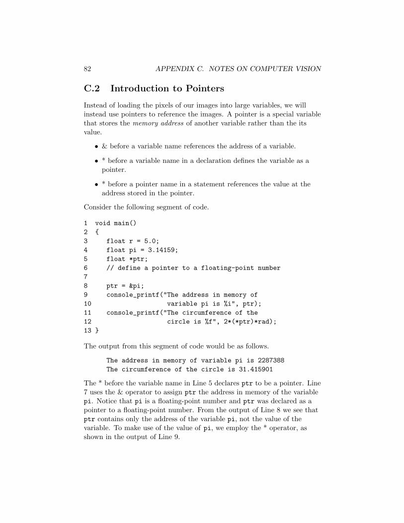
82 APPENDIX C. NOTES ON COMPUTER VISION
C.2 Introduction to Pointers
Instead of loading the pixels of our images into large variables, we willinstead use pointers to reference the images. A pointer is a special variablethat stores the memory address of another variable rather than the itsvalue.
• & before a variable name references the address of a variable.
• * before a variable name in a declaration defines the variable as apointer.
• * before a pointer name in a statement references the value at theaddress stored in the pointer.
Consider the following segment of code.
1 void main()
2 {
3 float r = 5.0;
4 float pi = 3.14159;
5 float *ptr;
6 // define a pointer to a floating-point number
7
8 ptr = π
9 console_printf("The address in memory of
10 variable pi is %i", ptr);
11 console_printf("The circumference of the
12 circle is %f", 2*(*ptr)*rad);
13 }
The output from this segment of code would be as follows.
The address in memory of variable pi is 2287388
The circumference of the circle is 31.415901
The * before the variable name in Line 5 declares ptr to be a pointer. Line7 uses the & operator to assign ptr the address in memory of the variablepi. Notice that pi is a floating-point number and ptr was declared as apointer to a floating-point number. From the output of Line 8 we see thatptr contains only the address of the variable pi, not the value of thevariable. To make use of the value of pi, we employ the * operator, asshown in the output of Line 9.

C.3. SIMPLIFYING CAMERA CALIBRATION 83
C.3 Simplifying Camera Calibration
In lab 6, we need to calibrate the camera. That is, we want to deriveformulas to compute an object’s coordinates in the world frame (x, y, z)w
based on row and column coordinates in the image (x, y)c. The necessarymath is found in chapter 11 of SH&V. For this lab, however, we may makea few assumptions that will greatly simplify the calculations. We beginwith the following intrinsic and extrinsic equations:
intrinsic:r = fx
zc xc +Or
c =fyzc y
c +Oc
extrinsic: pc = Rcwpw +Ocw
with the variables defined as in Table C.2.
The image we have is “looking straight down” the zc axis. Since the centerof the image corresponds to the center of the camera frame, (r, c) does notcorrespond to (xc, yc) = (0, 0). Therefore, you must adjust the row andcolumn values using (Or, Oc).

84 APPENDIX C. NOTES ON COMPUTER VISION
name description
(r, c) (row,column) coordinates of image pixelfx, fy ratio of focal length to physical width and length of a pixel
(Or, Oc) (row,column) coordinates of principal point of image(principal point of our image is center pixel)
(xc, yc) coordinates of point in camera framepc = [xcyczc]T coordinates of point in camera framepw = [xwywzw]T coordinates of point in world frameOcw = [TxTyTz]
T origin of world frame expressed in camera frameRcw rotation expressing camera frame w.r.t. world frame.
Table C.1: Definitions of variables necessary for camera calibration.
We also note that the row value is associated with the xc coordinate, andthe column value is associated with the yc coodinate. By this definition,and the way row and column increase in our image, we conclude that thezc axis points up from the table top and into the camera lens. This isdifferent than the description and figure in the text! (In order to match thetext, we would need row or column to increment in a reverse direction) Asa consequence, we define Rcw = Rz,θ instead of Rz,θRx,180◦ .
We make the following assumptions:
1. The z axis of the camera frame points straight up from the table top,so zc is parallel to zw. Modifying the equation from the text, we have
Rcw = Rz,θ
=
cθ −sθ 0sθ cθ 00 0 1
.2. All objects in our image will be the blocks we use in the lab, therefore
all objects have the same height. This means that zc in the intrinsicequations is the same for every object pixel. Since we can measurezc, we can ignore the computation of zc in the extrinsic equation.
3. The physical width and height of a pixel are equal (sx = sy).Together with assumption 2, we can define
β =fxzc
=fyzc.
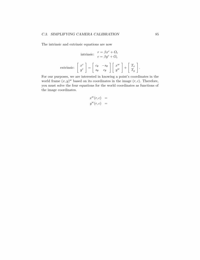
C.3. SIMPLIFYING CAMERA CALIBRATION 85
The intrinsic and extrinsic equations are now
intrinsic:r = βxc +Orc = βyc +Oc
extrinsic:
[xc
yc
]=
[cθ −sθsθ cθ
] [xw
yw
]+
[TxTy
].
For our purposes, we are interested in knowing a point’s coordinates in theworld frame (x, y)w based on its coordinates in the image (r, c). Therefore,you must solve the four equations for the world coordinates as functions ofthe image coordinates.
xw(r, c) =
yw(r, c) =