eb 8546 en - samson ag · the type 4708 supply pressure regulator reduces and controls the maximum...
TRANSCRIPT

Translation of original instructions
EB 8546 EN
Type 4708-12
Type 4708-53 Type 4708-64
Edition March 2018
Type 4708 Supply Pressure Regulators
Note on these mounting and operating instructions
These mounting and operating instructions assist you in mounting and operating the device safely. The instructions are binding for handling SAMSON devices.
Î For the safe and proper use of these instructions, read them carefully and keep them for later reference.
Î If you have any questions about these instructions, contact SAMSON‘s After-sales Service Department ([email protected]).
The mounting and operating instructions for the devices are included in the scope of delivery. The latest documentation is available on our website at www.samson.de > Service & Support > Downloads > Documentation.
Definition of signal words
Hazardous situations which, if not avoided, will result in death or serious injury
Hazardous situations which, if not avoided, could result in death or serious injury
Property damage message or malfunction
Additional information
Recommended action
DANGER!
WARNING!
NOTICE!
Note
Tip
2 EB 8546 EN

Contents
EB 8546 EN 3
1 Safety instructions and measures ...................................................................51.1 Notes on possible personal injury ...................................................................71.2 Notes on possible property damage ................................................................72 Design and principle of operation ..................................................................82.1 Versions ......................................................................................................102.2 Technical data .............................................................................................113 Mounting the supply pressure regulator .......................................................133.1 Compact supply pressure regulator ................................................................133.1.1 Direction of flow ..............................................................................................3.1.2 Turning the supply pressure regulator .............................................................143.2 Supply pressure regulators for attachment to positioners and actuators .............154 Pneumatic connections .................................................................................194.1 Pressure gauge ............................................................................................194.2 Additional output .........................................................................................205 Manual/automatic switchover .....................................................................225.1 Mounting on positioners ...............................................................................225.2 Mounting using an adapter plate ..................................................................235.3 Operating the manual/automatic switchover unit ...........................................245.4 Filter with filter receptacle .............................................................................245.4.1 Mounting the air filter ...................................................................................246 Rotating supplementary filter .......................................................................256.1 Mounting the rotating supplementary filter .....................................................257 Adjusting the set point .................................................................................258 Maintenance ...............................................................................................269 Troubleshooting...........................................................................................2710 Spare parts and accessories.........................................................................2810.1 Spare parts .................................................................................................2810.2 Accessories .................................................................................................2911 Dimensions in mm .......................................................................................30
4 EB 8546 EN
For details on the Type 4708-45 Supply Pressure Regulator (with increased air capacity), see u EB 8546-1.
Note

EB 8546 EN 5
Safety instructions and measures
1 Safety instructions and measuresIntended useThe Type 4708 Supply Pressure Regulator reduces and controls the maximum pressure of 12 bar (180 psi) in a compressed air network to the pressure adjusted at the set point adjust-er. The device is designed to operate under exactly defined conditions (e.g. operating pres-sure, temperature). Therefore, operators must ensure that the pressure regulator is only used in applications where the operating conditions correspond to the technical data. In case op-erators intend to use the pressure regulator in other applications or conditions than specified, contact SAMSON.SAMSON does not assume any liability for damage resulting from the failure to use the de-vice for its intended purpose or for damage caused by external forces or any other external factors.
Î Refer to the technical data for limits and fields of application as well as possible uses.
Reasonably foreseeable misuseThe Type 4708 Supply Pressure Regulator is not suitable for the following applications: − Use outside the limits defined during sizing and by the technical data
Furthermore, the following activities do not comply with the intended use: − Use of non-original spare parts − Performing maintenance activities not specified by SAMSON
Qualifications of operating personnelThe pressure regulator must be mounted, started up and serviced by fully trained and quali-fied personnel only; the accepted industry codes and practices are to be observed. Accord-ing to these mounting and operating instructions, trained personnel refers to individuals who are able to judge the work they are assigned to and recognize possible hazards due to their specialized training, their knowledge and experience as well as their knowledge of the appli-cable standards.
Personal protective equipmentNo personal protective equipment is required for the direct handling of the pressure regula-tor. Work on the control valve may be necessary when mounting or removing the device.
Î Observe the requirements for personal protective equipment specified in the valve docu-mentation.
Î Check with the plant operator for details on further protective equipment.
6 EB 8546 EN
Safety instructions and measures
Revisions and other modificationsRevisions, conversions or other modifications of the product are not authorized by SAMSON. They are performed at the user's own risk and may lead to safety hazards, for example. Fur-thermore, the product may no longer meet the requirements for its intended use.
Warning against residual hazardsTo avoid personal injury or property damage, plant operators and operating personnel must prevent hazards that could be caused in the pneumatic instrumentation by the signal pressure or by moving parts by taking appropriate precautions. They must observe all hazard state-ments, warning and caution notes in these mounting and operating instructions, especially for installation, start-up and service work.
Responsibilities of the operatorThe operator is responsible for proper operation and compliance with the safety regulations. Operators are obliged to provide these mounting and operating instructions to the operating personnel and to instruct them in proper operation. Furthermore, the operator must ensure that operating personnel or third persons are not exposed to any danger.
Responsibilities of operating personnelOperating personnel must read and understand these mounting and operating instructions as well as the specified hazard statements, warning and caution notes. Furthermore, the operat-ing personnel must be familiar with the applicable health, safety and accident prevention regulations and comply with them.
Referenced documentationThe following documents apply in addition to these mounting and operating instructions: − The mounting and operating instructions of the components on which the pressure regula-
tor is mounted (valve, actuator, positioner, etc.).
EB 8546 EN 7
Safety instructions and measures
1.1 Notes on possible personal injury
WARNING!
Risk of injury due to high pressure. Î Shut off the air line before performing work on the supply pressure regulator.
1.2 Notes on possible property damage
NOTICE!
Risk of damage to the pressure regulator due to excessively high tightening torque. Î Do not exceed the maximum permissible torques specified in these mounting and op-erating instructions.

8 EB 8546 EN
Design and principle of operation
2 Design and principle of oper-ation
The supply pressure regulator is used to sup-ply pneumatic measuring and control equip-ment with a constant air supply. The maxi-mum 12 bar pressure of the compressed air network in a plant is reduced to an adjust-able minimum pressure of 0.2 to 1.6 bar or 0.5 to 6 bar.At the inlet side, the supply pressure regula-tor is equipped with a filter cartridge with a mesh size of 20 μm. In addition, the regula-tor can also be equipped with a filter recep-tacle and a pressure gauge on the outlet side.
12
5
3
1
21
20
Fig. 1: Overview of Type 4708
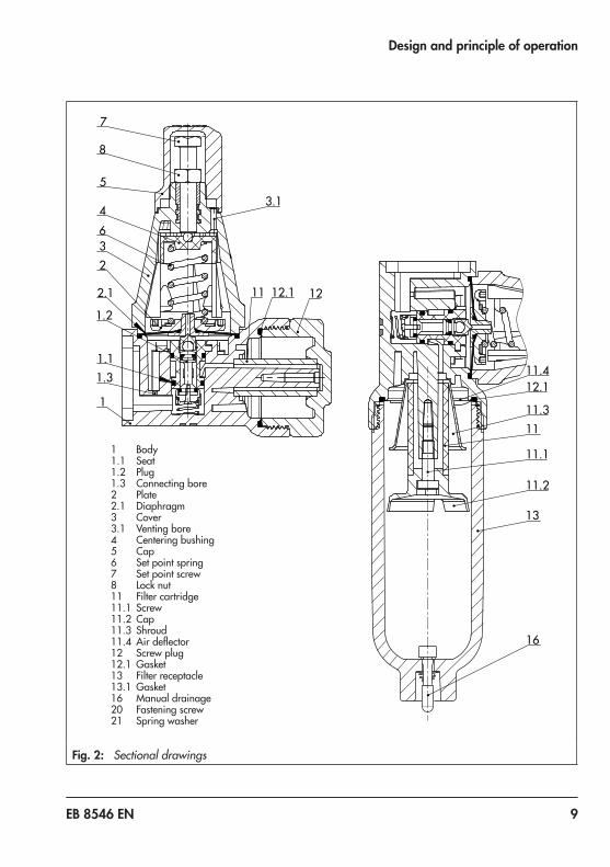
The compressed air at the inlet flows across the filter through the free cross-section be-tween the seat (1.1) and plug (1.2) and leaves the output with a reduced pressure depending on the plug position.The output pressure to be controlled is trans-mitted to the diaphragm (2.1) over the con-necting bore (1.3) and converted into a posi-tioning force. This force is used to move the valve plug depending on the force of the po-sitioning spring (6).Turning the set point screw (7) causes the spring force to change and, as a result, the required set point is adjusted.The set point ranges of the supply pressure regulator from 0.2 to 1.6 bar and 0.5 to 6 bar are determined by various tensions of the installed positioning spring (6).Condensed water contained in the com-pressed air can be collected and drained when the filter cartridge (11) is mounted hor-izontally or the filter receptacle (13) is sus-pended downwards. The screw plug (12) can be unscrewed or the manual drainage (16) can be activated to drain condensed water.
EB 8546 EN 9
Design and principle of operation
13
16
11
11.1
11.2
11.3
12.111.4
1 Body1.1 Seat1.2 Plug1.3 Connecting bore2 Plate2.1 Diaphragm3 Cover3.1 Venting bore4 Centering bushing5 Cap6 Set point spring7 Set point screw8 Lock nut11 Filter cartridge11.1 Screw11.2 Cap11.3 Shroud11.4 Air deflector12 Screw plug12.1 Gasket13 Filter receptacle13.1 Gasket16 Manual drainage20 Fastening screw21 Spring washer
11 12.1 12
3.1
7
8
5
4632
1.2
1.3
1
2.1
1.1
Fig. 2: Sectional drawings

10 EB 8546 EN
Design and principle of operation
2.1 VersionsSupply Pressure Regulator Type 4708- x x x xStandard version
Aluminum filter without filter receptacle 1 0
with plastic filter receptacle 1 1
with aluminum filter receptacle 1 2
Stainless steel version
Stainless steel filter with stainless steel filter receptacle 1 3
with plastic filter receptacle 1 4
without filter receptacle 1 7
Connection
G ¼ 2
¼-18 NPT 5
Set point range 0.5 to 6 bar (8 to 90 psi)
Without pressure gauge 0
with pressure gauge, completely free of copper 1
with pressure gauge, housing free of copper 2
Set point range 0.2 to 1.6 bar (3 to 23 psi)
Without pressure gauge 3
with pressure gauge, completely free of copper 4
with pressure gauge, housing free of copper 5
Supply pressure regulator with increased air capacity
u EB 8546-1 4 5
with adapter plate for positioners
Types 3730, 3766, 3767 5 3
Types 3725, 3730, 3766, 3767 5 4
Type 3725, Types 4763/4765 5 5 0
with adapter plate for pneumatic actuators
Type 3277 Actuator (240 to 700 cm²) with Type 3730, 3766 or 3767 Positioner 6 2 0
Type 3372 6 2
Type 3277 Actuator with connection block 6 4 0

EB 8546 EN 11
Design and principle of operation
Supply Pressure Regulator Type 4708- x x x xFor mounting onto Type 3379 Pneumatic Actuator
Mounting onto Type 3379 Actuator (31 cm²), G 1/8 6 5
Mounting onto Type 3379 Actuator (63 cm²), G ¼ 6 6
Manual/automatic switchover
Bypass for positioner 8 2
Filter without pressure gauge Type 4708-
Aluminum body and plastic filter receptacle 8 3 0
Aluminum body and aluminum filter receptacle 8 4 0
Stainless steel body and plastic filter receptacle 8 6 0
Stainless steel body and stainless steel filter receptacle 8 7 0
2.2 Technical data
Table 1: Technical data 1)
Supply pressure regulator Type 4708-xxSupply pressure 1.6 to 12 bar (24 to 180 psi)
Set point range 0.2 to 1.6 bar (3 to 24 psi) or 0.5 to 6 bar (8 to 90 psi)
Air consumption at 7 bar supply pressure ≤0.05 mn³/h
Dependency on inlet pressure < 0.01 bar/Δp = 1 bar
Reversing error 0.1 to 0.4 bar (depending on set point)
Hysteresis < 0.1 bar
Filter cartridge mesh size 20 µm · Optionally 5 µm
Compliance
Pressure gaugeIndicating range 0 to 1.6 bar (0 to 24 psi) or 0 to 6 bar (0 to 90 psi)
Connection G 1/8
1) Values measured for Type 4708-xx with ¼” connection and for Type 4708-45 with ½” connection
12 EB 8546 EN
Design and principle of operation
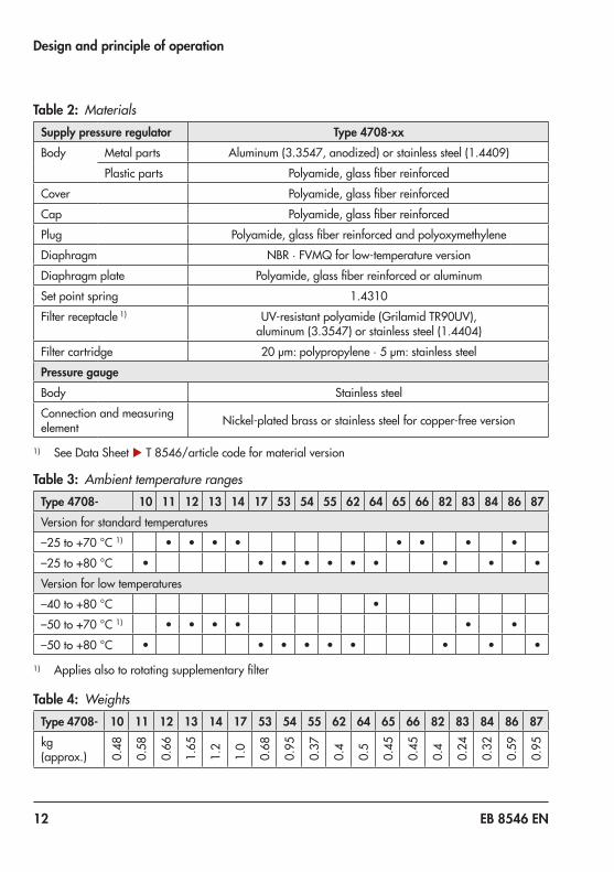
Table 2: MaterialsSupply pressure regulator Type 4708-xxBody Metal parts Aluminum (3.3547, anodized) or stainless steel (1.4409)
Plastic parts Polyamide, glass fiber reinforced
Cover Polyamide, glass fiber reinforced
Cap Polyamide, glass fiber reinforced
Plug Polyamide, glass fiber reinforced and polyoxymethylene
Diaphragm NBR · FVMQ for low-temperature version
Diaphragm plate Polyamide, glass fiber reinforced or aluminum
Set point spring 1.4310
Filter receptacle 1) UV-resistant polyamide (Grilamid TR90UV), aluminum (3.3547) or stainless steel (1.4404)
Filter cartridge 20 µm: polypropylene · 5 µm: stainless steel
Pressure gaugeBody Stainless steel
Connection and measuring element Nickel-plated brass or stainless steel for copper-free version
1) See Data Sheet u T 8546/article code for material version
Table 3: Ambient temperature rangesType 4708- 10 11 12 13 14 17 53 54 55 62 64 65 66 82 83 84 86 87Version for standard temperatures
–25 to +70 °C 1) • • • • • • • •
–25 to +80 °C • • • • • • • • • •
Version for low temperatures
–40 to +80 °C •
–50 to +70 °C 1) • • • • • •
–50 to +80 °C • • • • • • • • •
1) Applies also to rotating supplementary filter
Table 4: WeightsType 4708- 10 11 12 13 14 17 53 54 55 62 64 65 66 82 83 84 86 87kg (approx.) 0.
48
0.58
0.66
1.65
1.2
1.0
0.68
0.95
0.37
0.4
0.5
0.45
0.45
0.4
0.24
0.32
0.59
0.95
EB 8546 EN 13
Mounting the supply pressure regulator
3 Mounting the supply pressure regulator
Î To prevent excessive amounts of con-densed water from collecting, keep the distance between the compressor and supply pressure regulator as short as possible.
Î Make sure the drain plug faces down-wards in versions with a filter receptacle.
3.1 Compact supply pressure regulator
The supply pressure regulator can either be mounted directly in the pipeline of the air supply or on rails or brackets using the cor-responding mounting parts (see accessories in section 10.2).Observe the direction of flow of the supply air. An arrow on the nameplate indicates the direction.
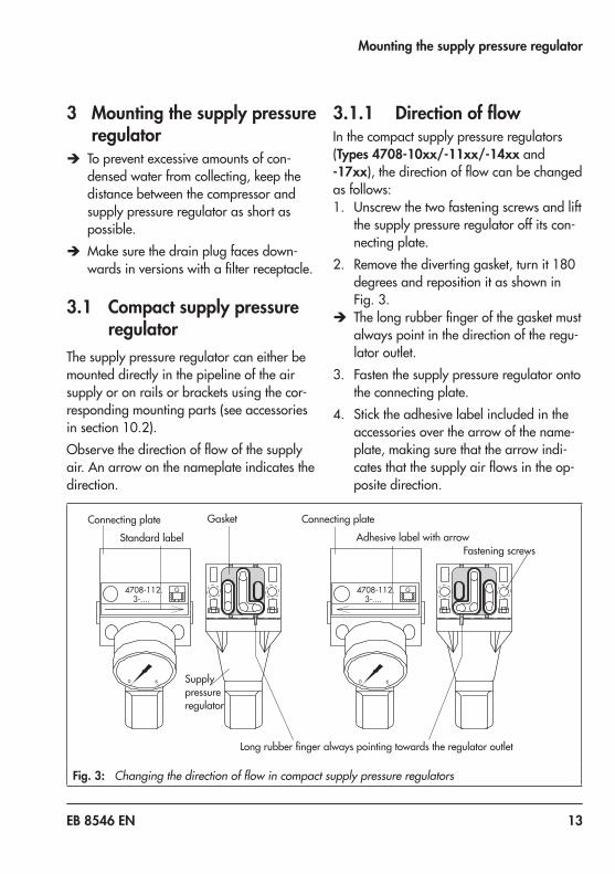
3.1.1 Direction of flowIn the compact supply pressure regulators (Types 4708-10xx/-11xx/-14xx and -17xx), the direction of flow can be changed as follows:1. Unscrew the two fastening screws and lift
the supply pressure regulator off its con-necting plate.
2. Remove the diverting gasket, turn it 180 degrees and reposition it as shown in Fig. 3.
Î The long rubber finger of the gasket must always point in the direction of the regu-lator outlet.
3. Fasten the supply pressure regulator onto the connecting plate.
4. Stick the adhesive label included in the accessories over the arrow of the name-plate, making sure that the arrow indi-cates that the supply air flows in the op-posite direction.
G4708-112.
0 6
3-....
0 6
3-....4708-112. G
Connecting plate
Standard label
GasketConnecting plateAdhesive label with arrow
Fastening screws
Long rubber finger always pointing towards the regulator outlet
Supply pressure regulator
Fig. 3: Changing the direction of flow in compact supply pressure regulators

14 EB 8546 EN
Mounting the supply pressure regulator
3.1.2 Turning the supply pres-sure regulator
The supply pressure regulator can be turned on its connecting plate to allow the set point screw to face either up or down.1. Unscrew the two fastening screws and lift
the supply pressure regulator off its con-necting plate.
2. Pull the diverting gasket out of the regu-lator and keep it in this position.
3. Turn the regulator 180 degrees and rein-sert the gasket. In this way, you keep the bore assignment of the gasket for supply air input and regulator outlet.
Î The long rubber finger of the gasket must always point in the direction of the regu-lator outlet (reduced supply pressure).
4. Fasten the supply pressure regulator onto the connecting plate.
Diverting gasket Front and back view
Regulator outlet
Supply air inputdepending on the position of the gasket
Regulator outlet (long rubber finger)
Supply air input
Regulator facing upward
Supply air input(Supply) >
Diverting gasket Long rubber finger always pointing towards outlet
Regulator facing downward
Fastening screws
Connecting plate or adapter plate
Fig. 4: Turning the supply pressure regulator on its connecting plate or adapter plate

EB 8546 EN 15
Mounting the supply pressure regulator
3.2 Supply pressure regulators for attachment to posi-tioners and actuators
The supply pressure regulator versions in-tended for attachment to positioners and ac-tuators are equipped with various adapter plates for the attachment.If required, the installation position of the supply pressure regulator can be changed by turning it 180° on its adapter plate to al-low the set point screw to face either up or down.This applies particularly to positioners that can be mounted either to the left or right side of the valve yoke to determine the operating direction and fail-safe action of the actuator.To turn the supply pressure regulator, pro-ceed as described in section 3.1.2.The regulator is turned on its adapter plate instead of on the connecting plate.
Supply pressure regulator for positionerType 3730/3766/3767/3787Type 4708-53xx for Type 3271 Actuator and Type 3277 Actuator (120, 240 to 700 cm²) with hooked-up valve accessories1. Insert the gasket (2) into the recess of the
adapter plate (1).2. Place the supply pressure regulator on
the positioner on the side where the pneumatic connections SUPPLY and OUTPUT are located. Screw tight using the two M5 screws (3).
Type 4708-54xx for rotary actuatorsProceed to mount as Type 4708-53xx.
Type 4708-54xx has a second output sealed with a stopper. This is intended for reduced supply air. It can be used to supply a second device, if required (e.g. a pilot-operated so-lenoid valve).
Type 4708-53xx
Type 4708-54xx
Fig. 5: Attachment on positioners

16 EB 8546 EN
Mounting the supply pressure regulator
Type 4708-55xx for Types 3725, 4763 and 4765 Positioners1. Screw the special nuts (5) into the connect-
ing holes of the positioner.2. Insert the gasket (2) into the recess of the
adapter plate (1).3. Slide the special hollow screws (6) for
SUPPLY and (7) for OUTPUT into the con-necting holes of adapter plate (1).
4. Place the supply pressure regulator onto the positioner and fasten it using the two special screws.
5. Seal the spare connections with stoppers (4) to prevent dirt from entering the de-vice.
Type 4708-64xx for Type 3277 ActuatorBefore mounting, check whether the tip of the gasket (1.2) projecting from the side of the connection block (1) is positioned to match the actuator symbol (1.3) for the actu-ator's fail-safe action "actuator stem ex-tends" or "actuator stem retracts". If this is not the case, proceed as follows:1. Unscrew the three Phillips screws (3.1),
lift off the cover (1.1). Turn the gasket (1.2) by 180° and re-insert it. Continue with reassembly.
2. Place the connection block (1) with the inserted O-ring against the positioner and actuator yoke and fasten using the hexagonal socket screw (3).
3. Place the supply pressure regulator with O-ring on the connection block and fas-ten it with hexagonal socket screw (2).
60
SAMSON 4763
4708-552.
60
17
6
5
5
2
1
4
4
10
17
9
6
1
5
5
Fig. 6: Attachment to Types 4763 and 4735 Positioners
23
1
1
3.1
3.1
1.2
1.3
1.31.1
1.2
Fig. 7: Mounting on Type 3277 Actuator

EB 8546 EN 17
Mounting the supply pressure regulator
Type 4708-62xx for Type 3372 Actuator1. Screw the special nut (5) into the SUPPLY
connecting hole of the actuator.2. Slide the special hollow screw (6) into the
connection hole of the adapter plate.
3. Insert the O-ring (9). Position the supply pressure regulator and fasten it to the ac-tuator using the special screw.
4. Seal the spare connections with stoppers (4) to prevent dirt from entering the de-vice.
195
64
165
94
Fig. 8: Mounting on Type 3372 Actuator
18 EB 8546 EN
Mounting the supply pressure regulator
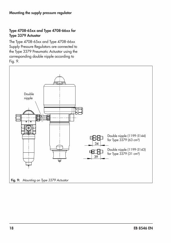
Double nipple (1199-5144) for Type 3379 (63 cm²)
Double nipple (1199-5143) for Type 3379 (31 cm²)
67
43
39
34
Double nipple
Fig. 9: Mounting on Type 3379 Actuator
Type 4708-65xx and Type 4708-66xx for Type 3379 ActuatorThe Type 4708-65xx and Type 4708-66xx Supply Pressure Regulators are connected to the Type 3379 Pneumatic Actuator using the corresponding double nipple according to Fig. 9.
EB 8546 EN 19
Pneumatic connections
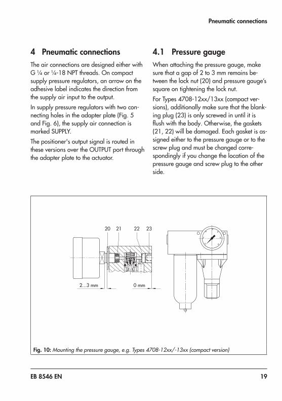
4 Pneumatic connectionsThe air connections are designed either with G ¼ or ¼-18 NPT threads. On compact supply pressure regulators, an arrow on the adhesive label indicates the direction from the supply air input to the output.In supply pressure regulators with two con-necting holes in the adapter plate (Fig. 5 and Fig. 6), the supply air connection is marked SUPPLY.The positioner's output signal is routed in these versions over the OUTPUT port through the adapter plate to the actuator.
4.1 Pressure gaugeWhen attaching the pressure gauge, make sure that a gap of 2 to 3 mm remains be-tween the lock nut (20) and pressure gauge’s square on tightening the lock nut.For Types 4708-12xx/13xx (compact ver-sions), additionally make sure that the blank-ing plug (23) is only screwed in until it is flush with the body. Otherwise, the gaskets (21, 22) will be damaged. Each gasket is as-signed either to the pressure gauge or to the screw plug and must be changed corre-spondingly if you change the location of the pressure gauge and screw plug to the other side.
20 22
2...3 mm 0 mm
21 23
Fig. 10: Mounting the pressure gauge, e.g. Types 4708-12xx/-13xx (compact version)
20 EB 8546 EN
Pneumatic connections
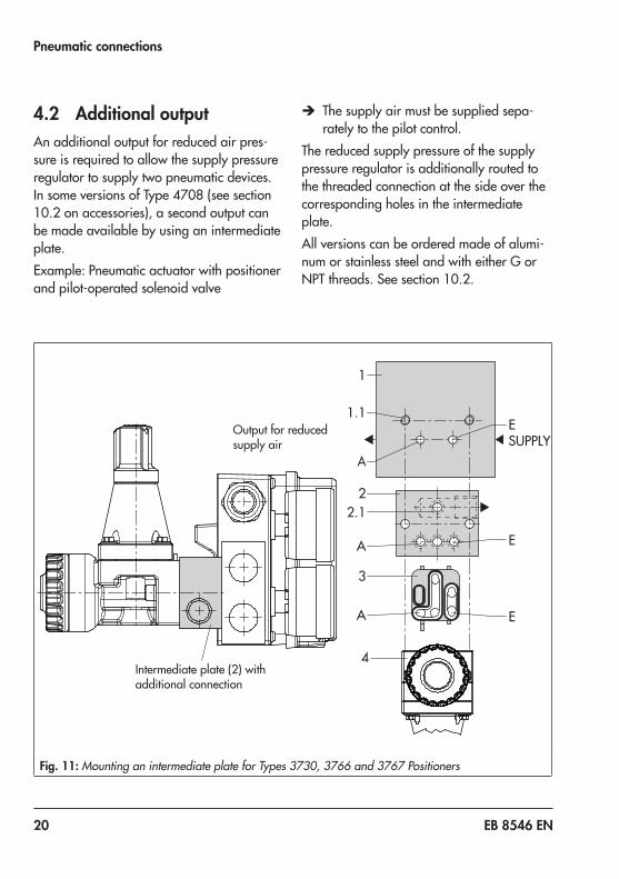
4.2 Additional outputAn additional output for reduced air pres-sure is required to allow the supply pressure regulator to supply two pneumatic devices. In some versions of Type 4708 (see section 10.2 on accessories), a second output can be made available by using an intermediate plate.Example: Pneumatic actuator with positioner and pilot-operated solenoid valve
Î The supply air must be supplied sepa-rately to the pilot control.
The reduced supply pressure of the supply pressure regulator is additionally routed to the threaded connection at the side over the corresponding holes in the intermediate plate.All versions can be ordered made of alumi-num or stainless steel and with either G or NPT threads. See section 10.2.
1
1.1
A
A
A
ESUPPLY
22.1
3
4
E
E
Output for reduced supply air
Intermediate plate (2) with additional connection
Fig. 11: Mounting an intermediate plate for Types 3730, 3766 and 3767 Positioners

EB 8546 EN 21
Pneumatic connections
Mounting the intermediate plate1. Remove the fastening screws and lift the
supply pressure regulator (4) together with the diverting gasket (3) off the adapter plate (1). Make sure you do not change the position of the diverting gas-ket in the supply pressure regulator.
Î The long rubber finger of the diverting gasket (3) must always point toward the regulator outlet (reduced supply pres-sure). See Fig. 11 and Fig. 12.
2. Insert the O-rings (2.1) into the bore-holes of the intermediate plate (2).
3. Place the intermediate plate onto the connecting or adapter plate in such a way that their three boreholes (arranged in row) are located over the two 5 mm boreholes of the adapter plate and the boreholes (1.1) for the fastening screws are aligned correctly.
4. Place the supply pressure regulator (4) with the diverting gasket (3) onto the in-termediate plate (2). Insert the longer fastening screws and fasten the parts.
11.1
EA
2
2.1
3
A
AE
AE
4
Output for reduced air
Supply air input
2
Fig. 12: Mounting an intermediate plate onto Type 3372 Actuator

22 EB 8546 EN
Manual/automatic switchover
5 Manual/automatic switcho-ver
The positioner output is routed to the actua-tor over the manual/automatic switchover. In automatic mode, the positioner is in closed-loop operation. In manual mode, the output pressure of any supply pressure regulator is directly applied to the actuator. This creates a manual bypass of the positioner.The manual/automatic switchover unit is mounted directly onto Types 376x and 373x (see Fig. 13) or on an adapter plate with hook-up to the actuator (Fig. 16).The Type 4708-53 or Type 4708-54 Supply Pressure Regulator can be directly mounted. All other supply pressure regulators can be connected to the manual/automatic switcho-ver unit using piping (hook-up).
5.1 Mounting on positioners
Fig. 13: Mounting on positioners
− Insert gasket into recess of the manual/automatic switchover unit.
− Fasten the manual/automatic switchover unit to the positioner using the two hex-agonal socket screws.
− Connect hook-up to the SUPPLY and OUTPUT connections of the manual/au-tomatic switchover unit.
1 Pneumatic control valve with positioner
2 Adapter plate: 1400-9605 (G), 1400-9606 (NPT)
3 Type 4708-82 Manual/au-tomatic Switchover in AUTO mode
4 Supply pressure regulator with filter (e.g. Type 4708-10)
Output (38)
Supply (9)
Supply
Output
1
2
3
4
Fig. 14: Mounting the manual/automatic switchover using an adapter plate

EB 8546 EN 23
Manual/automatic switchover
Optionally, a Type 4708-53 Supply Pressure Regulator can be mounted upstream of the manual/automatic switchover unit (Fig. 15).
Fig. 15: Type 4708-82 Manual/automatic Swi-tchover, Type 4708-53 Supply Pressure Regulator with pressure gauges and fil-ter receptacle
5.2 Mounting using an adapter plate
− Fasten adapter plate, for example to a NAMUR rib using a hexagonal socket screw.
− Fit the gasket on the manual/automatic switchover unit. Fasten it to the adapter plate using the two hexagonal socket screws.
Fig. 16: Mounting using an adapter plate
− Connect hook-up for positioner and actu-ator as shown in Fig. 14.
24 EB 8546 EN
Manual/automatic switchover
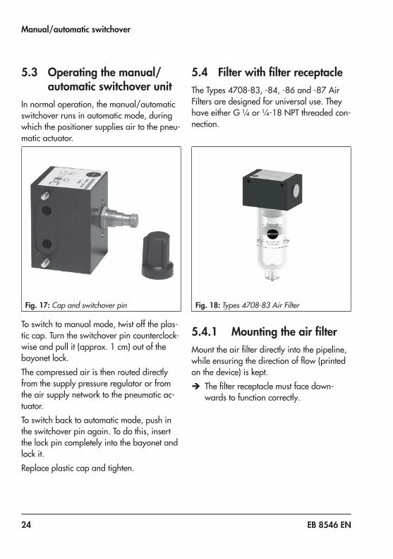
5.3 Operating the manual/automatic switchover unit
In normal operation, the manual/automatic switchover runs in automatic mode, during which the positioner supplies air to the pneu-matic actuator.
Fig. 17: Cap and switchover pin
To switch to manual mode, twist off the plas-tic cap. Turn the switchover pin counterclock-wise and pull it (approx. 1 cm) out of the bayonet lock.The compressed air is then routed directly from the supply pressure regulator or from the air supply network to the pneumatic ac-tuator.To switch back to automatic mode, push in the switchover pin again. To do this, insert the lock pin completely into the bayonet and lock it.Replace plastic cap and tighten.
5.4 Filter with filter receptacleThe Types 4708-83, -84, -86 and -87 Air Filters are designed for universal use. They have either G ¼ or ¼-18 NPT threaded con-nection.
Fig. 18: Types 4708-83 Air Filter
5.4.1 Mounting the air filterMount the air filter directly into the pipeline, while ensuring the direction of flow (printed on the device) is kept.
Î The filter receptacle must face down-wards to function correctly.
EB 8546 EN 25
Rotating supplementary filter
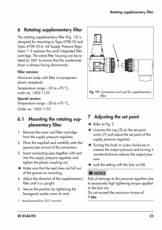
6 Rotating supplementary filterThe rotating supplementary filter (Fig. 15) is designed for mounting to Type 4708-53 and Types 4708-55 to -64 Supply Pressure Regu-lators 1). It replaces the small integrated filter cartridge. The entire filter housing can be ro-tated by 360° to ensure that the condensate drain is always facing downwards.
Filter versionsAluminum body with filter in transparent plastic receptacleTemperature range: –25 to +70 °C, order no. 1402-1132Special version:Temperature range: –50 to +70 °C,Order no. 1402-1133
6.1 Mounting the rotating sup-plementary filter
1. Remove the cover and filter cartridge from the supply pressure regulator.
2. Place the supplied seal carefully onto the groove (see arrow) of the connection.
3. Insert connecting pipe together with seal into the supply pressure regulator and tighten the plastic coupling nut.
Î Make sure that the seal does not fall out of the groove on mounting.
4. Adjust the direction of the supplementary filter until it is upright.
5. Secure the position by tightening the hexagonal socket screw (6 mm).
1) Manufactured from 2017 onwards
Fig. 19: Connection and seal for supplementary filter
7 Adjusting the set point Î Refer to Fig. 2 Î Unscrew the cap (5) on the set point screw (7) and adjust the set point of the supply pressure regulator.
Î Turning the knob or screw clockwise in-creases the output pressure and turning it counterclockwise reduces the output pres-sure.
Î Lock the setting with the lock nut (8).
Risk of damage to the pressure regulator due to excessively high tightening torque applied to the lock nut.Do not exceed the maximum torque of 7 Nm.
NOTICE!
26 EB 8546 EN
Maintenance
8 Maintenance
Risk of injury due to high pressure.Shut off the air line before performing work on the supply pressure regulator.
Drain condensed water that has collected: Î Activate the manual drainage. Î Replace the gasket (order no. 0439-0061), if necessary.
We recommend to check the filter as often as possible.
WARNING!
Tip

EB 8546 EN 27
Troubleshooting
9 Troubleshooting
Risk of injury due to high pressure.Shut off the air line before performing work on the supply pressure regulator.
Leakage between supply pressure regulator and adapter plate:
Î Check whether the diverting gasket (Fig. 3 and Fig. 4) is installed and the two fastening screws are tightened prop-erly.
Excessive blow-off over the venting bore: Î Check whether the diverting gasket (Fig. 3 and Fig. 4) is installed correctly.
Air capacity drops and the output pressure drops:
Î Check the filter cartridge for dirt and make sure the set point is correctly ad-justed.
Pressure drop Î Unscrew the filter receptacle and renew the filter cartridge (order no. 8504-9027).
WARNING!

28 EB 8546 EN
Spare parts and accessories
10 Spare parts and accessories10.1 Spare parts
Î See Fig. 2 on page 9.
Article Order numbersFilterFilter cartridge (11) 20 µm, polyethyleneFilter cartridge (11) 5 µm including gasket, polyethyleneFilter cartridge (11) 5 µm, sintered stainless steel
8504-90278504-90301400-9609
Filter partsScrew (11.1)Cap (11.2)Shroud (11.3)Air deflector (11.4)
8336-07900339-00180339-00170339-0016
Filter receptacle and screw plugFilter receptacle (13), plastic 1)
Filter receptacle (13), aluminum 1)
Filter receptacle (13), stainless steel 1)
Screw plug (12)
1199-04231199-04241199-04250079-0143
Seals for filter receptacle (12.1)For Type 4708 -10 -11 -12 -13 -14 -17 -53 -54 -55 -62 -64
PVMQ • • • • • • • • • 8421-9123NBR (free of silicone) • • • • • • • • • 8421-0099PVMQ • • 0439-0309NBR (free of silicone) • • 0439-0061Pressure gaugesPressure gauge, entirely made of stainless steel (0 to 6 bar)Pressure gauge, made of brass/stainless steel (0 to 6 bar)Lock nut
0089-00090089-00180250-1949
Pressure gauge seal 1099-4305Pressure gauge, entirely made of stainless steel (0 to 1.6 bar)Pressure gauge, made of brass/stainless steel (0 to 1.6 bar)Pressure gauge, entirely of stainless steel (0 to 1.6 bar), inc. pressure compensation elementPressure gauge, of brass/stainless steel (0 to 1.6 bar), inc. pressure compensation elementPressure gauge, entirely of st. steel (0 to 6 bar), inc. pressure compensation elementPressure gauge, brass/st. steel (0 to 6 bar), inc. pressure compensation element
0089-00140089-00080089-0027
0089-0028
0089-00250089-0026
1) Version compatible with paint on request

EB 8546 EN 29
Spare parts and accessories
10.2 AccessoriesAccessories Order no.
Mounting parts for rail mounting according to EN 50022According to EN 50035
1400-73411400-7342
Mounting parts for mounting on bracket for Type 3271 or Type 3277 Actuator 1402-0157
Intermediate plate for additional connection with Type 4708-10xx/-11xx/-53xx/-55xx/-62xx Supply Pressure Regulator (not required for Type 4708-54xx)
Aluminum with G ¼ threadAluminum with ¼ NPT threadStainless steel with G ¼ threadStainless steel with ¼ NPT thread
1400-74001400-74041400-74021400-7406
Special screw to mount Type 4708-54xx on Type 3710 Reversing Amplifier 1400-7806
Adjustment knob for set point adjustment 1400-7408
Nut for panel mounting 1400-7725
Adapter plate for manual/automatic switchover (Type 4708-82)
Aluminum with G ¼ threadAluminum with ¼ NPT threadStainless steel with G ¼ threadStainless steel with ¼ NPT thread
1400-96051400-96061400-96071400-9608
Adapter plate (from Type 3710) to mount Type 4708-53 on all old ver-sions of Types 3766, 3767 or 3780 Positioner 1400-9621
Filter cartridge 5 µm, sintered stainless steel (replacement part) 1400-9609
Rotating supplementary filter 1) for Type 4708-55 to -64:Temperature range: –25 to +70 °CTemperature range: –50 to +70 °C
1402-11321402-1133
Grease for silicone-free versionGrease for natural gas versionGrease for low-temperature version
1402-11491402-11501402-1151
1) Manufactured from 2017 onwards

30 EB 8546 EN
Dimensions in mm
11 Dimensions in mm(specifications in parentheses apply to additional compressed air connection, see page 39)
166
19
80 53
43
Output or Supply
Supply or Output
44
60
88
(112
) 1
9 51
43 53
80
44
60
Output or Supply
Output or Supply
Types 4708-10xx/-17xxTypes 4708-11xx/14xx

EB 8546 EN 31
Dimensions in mm
106 8
195
73
110
67
Output
Supply
70
80
28
51
7.7
75 (99)
Supply
Output
Type 4708-54xx mounted onto Type 3725 Positioner
Type 4708-53xx mounted onto Types 376x and 373x Positioners
32 EB 8546 EN
Dimensions in mm
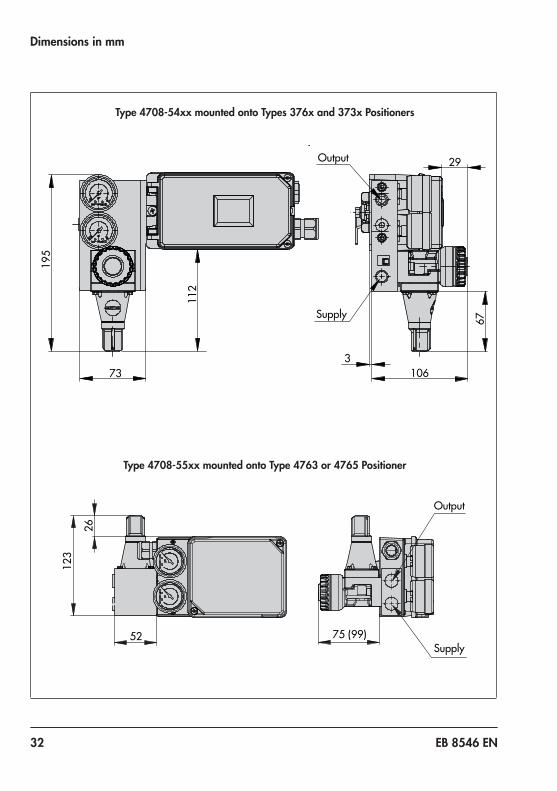
112
195
73 3
67
106
29 Output
Supply
123
26
52 75 (99) Supply
Output
Type 4708-54xx mounted onto Types 376x and 373x Positioners
Type 4708-55xx mounted onto Type 4763 or 4765 Positioner

EB 8546 EN 33
Dimensions in mm
Type 4708-64xx for Type 3277 Pneumatic Actuator and Type 376x or 373x Positioner
Type 4708-64xx for Type 3277 Pneumatic Actuator and Type 3725 Positioner
178
123 97
126
1
04
116
38
40 74
154
126
1
04
100 127
116
116
3
8
74 40

34 EB 8546 EN
Dimensions in mm
95 100
51
138
133
1
42
Ø41
44
12
102
OutputSupply
59
99
42
Type 4708-55xx mounted onto Type 3725 Positioner
Types 4708-12xx/-13xx Supply Pressure Regulators

EB 8546 EN 35
Dimensions in mm
Types 4708-83xx/-84xx/-86xx/-87xx Air Filter
Rotatable filter receptacle
44
15
42
115
59
45
50
146
78
Ø38.3
55
18
36 EB 8546 EN
Dimensions in mm
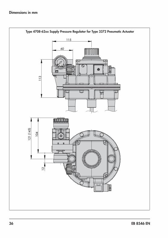
113
60
115
121
(145
)
104
12
Type 4708-62xx Supply Pressure Regulator for Type 3372 Pneumatic Actuator

EB 8546 EN 37
Dimensions in mm
97
141
50
167
194
83
132
11
9469
Type 4708-65xx Supply Pressure Regulator for Type 3379 Pneumatic Actuator (31 cm²)

38 EB 8546 EN
Dimensions in mm
106 150
50
69
167
1
94
11 83
132
94
Type 4708-66xx Supply Pressure Regulator for Type 3379 Pneumatic Actuator (63 cm²)

EB 8546 EN 39
Dimensions in mm
Intermediate plate for additional compressed air shown here: Type 4708-55xx
24
99
40 EB 8546 EN
Dimensions in mm
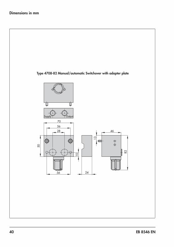
Type 4708-82 Manual/automatic Switchover with adapter plate
70
Supply Output
56
56
46
24
82
28
50
13
10

EB 8546 EN 41

42 EB 8546 EN

EB 8546 EN 43

2018
-10-
09 ·
Engl
ish
SAMSON AKTIENGESELLSCHAFTWeismüllerstraße 3 · 60314 Frankfurt am Main, GermanyPhone: +49 69 4009-0 · Fax: +49 69 [email protected] · www.samson.de
EB 8546 EN