east yelland power station - 361 energy
TRANSCRIPT
•
664 THE ENGINEER
East Yelland Power Station As recorded briefly in last week's issue, East Ye/land power station, between Barnstaple and Bideford, was officially opened on April 21st by the Earl Fortescue, Lord Lieutenant of Devon. The first half of the station is in commission, the main plant consisting of six 180 k lb per hour boilers, fired by chain grate stokers and supplying steam at 600 lb per square inch and 850 deg. Fah. to three 30MW, 3000 r.p.m. turbo-alternators. Circulating water is taken from the River Taw
estuary.
EAST YELLAND power station is the first large coal-burning station in the Barnstaple
Bideford region which hitherto has been supplied with electricity mainly by diesel-driven generators. The new station, with its present installed capacity of 90MW (ultimately to be increased to 180MW), will, however, be able to meet much more than purely local needs. Approximately 25 per cent of the present output will supply the demands of North Devon, while the remainder will be transmitted to Taunton and Cornwall.
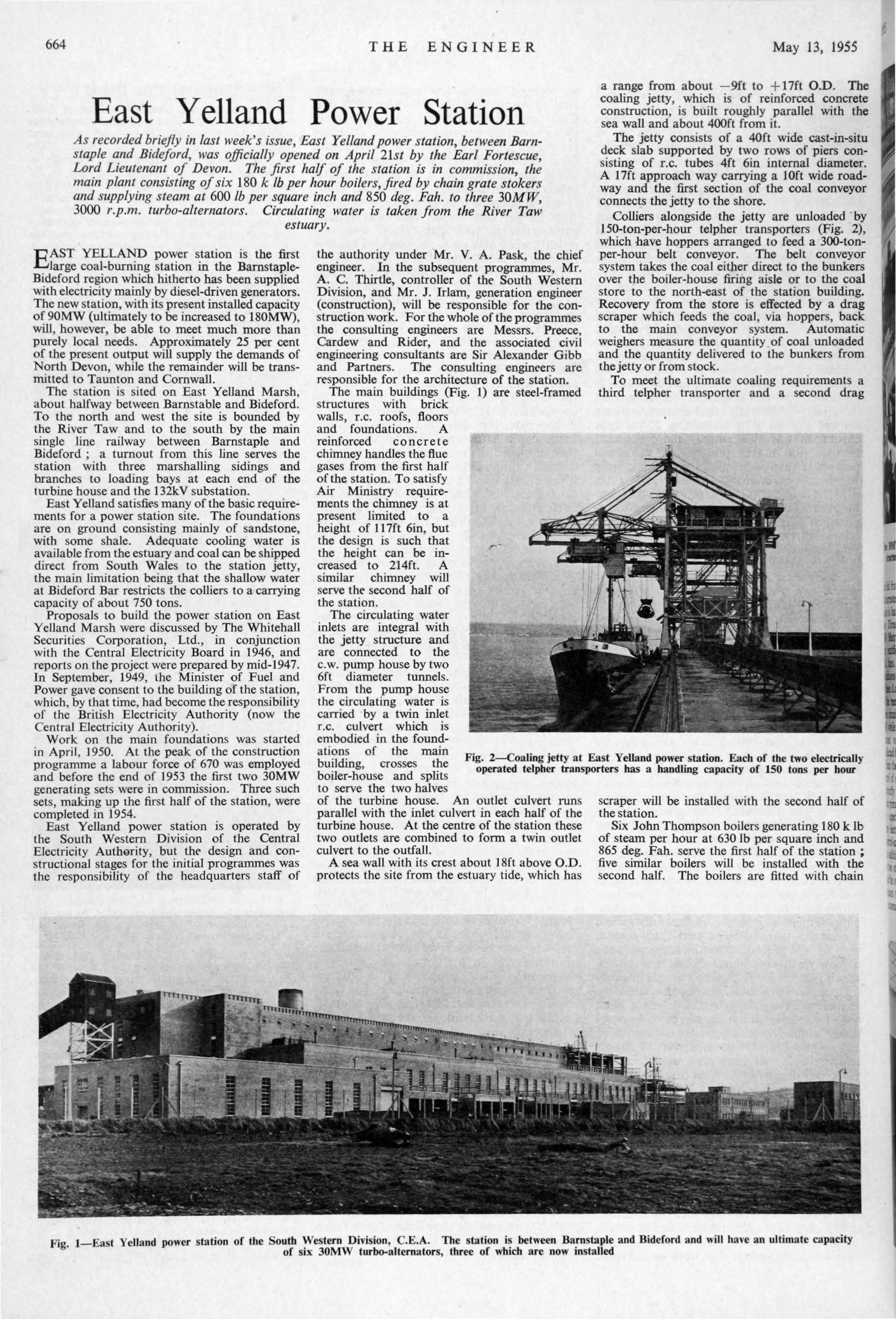
The station is sited on East Yelland Marsh, about halfway between Barnstable and Bideford. To the north and west the site is bounded by the River Taw and to the south by the main single line railway between Barnstaple and Bideford ; a turnout from this line serves the station with three marshalling sidings and branches to loading bays at each end of the turbine house and the 132kV substation.
East Yelland satisfie.s many of the basic requirements for a power station site. The foundations are on ground consisting mainly of sandstone, with some shale. Adequate cooling water is available from the estuary and coal can be shipped direct from South Wales to the station jetty, the main limitation being that the shallow water at Bideford Bar restricts the colliers to a carrying capacity of about 750 tons.
Proposals to build the power station on East Yelland Marsh were discussed by The Whitehall Securities Corporation, Ltd., in conjunction with the Central Electricity Board in 1946, and reports on the project were prepared by mid-1947. In September, 1949, the Minister of Fuel and Power gave consent to the building of the station, which , by that time, had become the responsibility of the British E lectricity Authority (now the Central E lectricity Authority).
the authority under Mr. V. A. Pask, the chief engineer. In the subsequent programmes, Mr. A. C. Thirtle, controller of the South Western Division, and Mr. J. Irlam, generation engineer (construction), will be responsible for the construction work. For the whole of the programmes the consulting engineers are Messrs. Preece, Cardew and Rider, and the associated civil engineering consultants are Sir Alexander Gibb and Partners. The consulting engineers are responsible for the architecture of the station.
The main buildings (Fig. 1) are steel-framed structures with brick walls, r .c. roofs, floors and foundations. A reinforced concrete chimney handles the flue gases from the first half of the station. To satisfy Air Ministry requirements the chimney is at present limited to a height of 117ft 6in, but the design is such that the height can be increased to 214ft. A similar chimney will serve the second half of the station.
-•
•
May 13, 1955
a range from about - 9ft to + 17ft O.D. The coaling jetty, which is of reinforced concrete construction, is built roughly parallel with the sea wall and about 400ft from it.
The jetty consists of a 40ft wide cast-in-situ deck slab supported by two rows of piers consisting of r.c. tubes 4ft 6in internal diameter. A 17ft approach way carrying a 1Oft wide roadway and the first section of the coal conveyor connects the jetty to the shore.
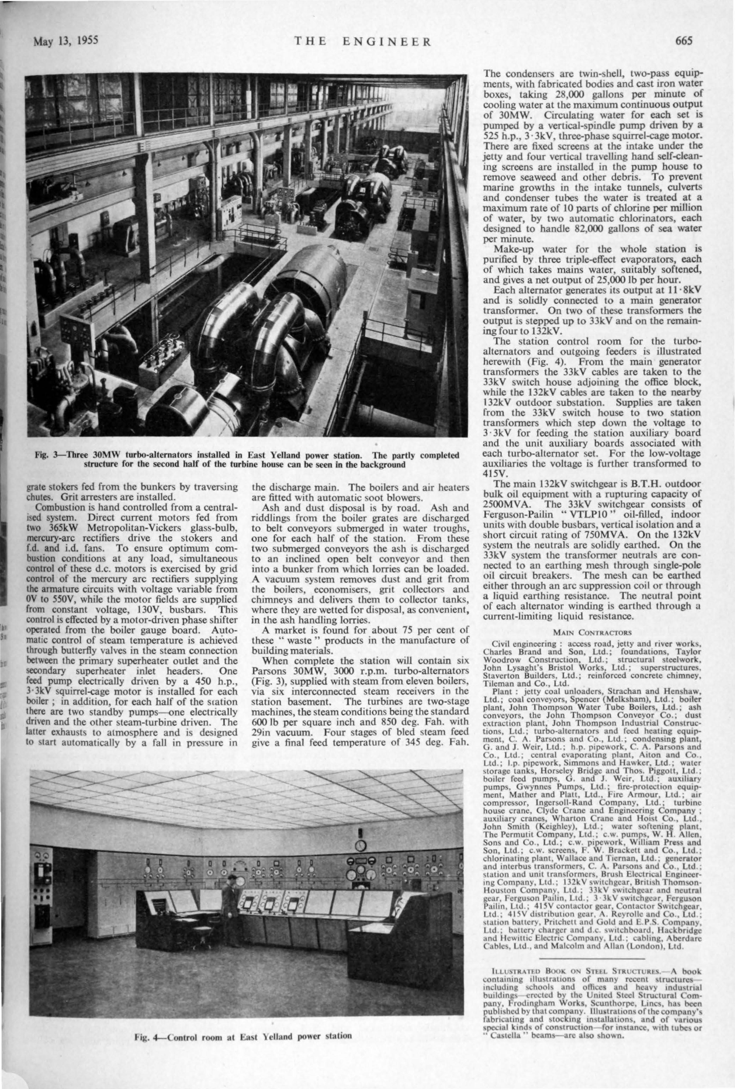
Colliers alongside the jetty are unloaded ·by 150-ton-per-hour telpher transporters (Fig. 2), which have hoppers arranged to feed a 300-tonper-hour belt conveyor. The belt conveyor system takes the coal either direct to the bunkers over the boiler-house firing aisle or to the coal store to the north-east of the station building. Recovery from the store is effected by a drag scraper which feeds the coal, via hoppers, back to the main conveyor system. Automatic weighers measure the quantity . of coal unloaded and the quantity delivered to the bunkers from the jetty or from stock.
To meet the ultimate coaling requirements a third telpher transporter and a second drag
•
.. ~.
Work on the main foundations was started in April , 1950. At the peak of the construction programme a labour force of 670 was employed and before the end of 1953 the first two 30MW generating sets were in commission. Three such sets, making up the first half of the station, were completed in 1954.
The circulating water inlets are integral with the jetty structure and are connected to the c. w. pump house by two 6ft diameter tunnels. From the pump house the circulating water is carried by a twin inlet r.c. culvert which is embodied in the foundations of the main building, crosses the boiler-house and splits to serve the two halves
Fig. 2-Coaling jetty at East Yelland power station. Each of the two electrically operated telpher transporters has a handling capacity of 150 tons per hour
East Yelland power station is operated by the South Western Division of the Central Electricity Authority, but th~ design and constructional stages for the initial programmes was the responsibility of the headquarters staff of
of the turbine house. An outlet culvert runs parallel with the inlet culvert in each half of the turbine house. At the centre of the station these two outlets are combined to fonn a twin outlet culvert to the outfall.
A sea wall with its crest about 18ft above O.D . protects the site from the estuary tide, which has
scraper will be installed with the second half of the station.
Six John Thompson boilers generating 180 k lb of steam per hour at 630 lb per square inch and 865 deg. Fah. serve the first half of the station ; five similar boilers will be installed with the second half. The boilers are fitted with chain
Fig l -East Yelland power station of the South Western Division, C.E.A. The station is between Barnstaple and Bideford and will have an ultimate capacity · of six 30MW turbo-alternators, three of which are now installed
I
'
May 13, 1955 THE ENGINEER
•
Fig. 3-Three 30MW turbo-alternators installed in East Yelland power station. The partly completed structure for the second half of the turbine house can be seen in the background
grate stokers fed from the bunkers by traver ing chutes. Grit arrester are installed.
Combustion is hand controlled from a centrali ed system. Direct current motors fed from two 365kW Metropolitan-Vickers glass-bulb, mercury-arc rectifiers drive the stokers and f.d. and i.d. fan . To ensure optimum combustion condition at any load, simultaneou control of these d.c. motors is exercised by grid control of the mercury arc rectifiers supplying the armature circuits with voltage variable from OV to 550V, while the motor fields are supplied from constant voltage, 130V, busbars. Thi control is effected by a motor-driven phase hifter operated from the boiler gauge board. Automatte control of steam temperature is achieved through butterfly valves in the steam connection between the primary superheater outlet and the ~ndary superheater inlet headers. One feed pump electrically driven by a 450 b.p., 3·3kV squirrel-cage motor is installed for each botler ; in addition, for each half of the scation there are two standby pumps one electrically drive-n and the other team-turbine driven. The latter exhaust to atmosphere and is designed to \tart automatically by a fall in pres~ure in
the discharge main. The boilers and aJr heater::. are fitted with automatic oot blower .
Ash and dust disposal i by road. Ash and riddling fron1 the boiler grate are di charged to belt conveyors submerged in water trough , one for each half of the station. From these two submerged conveyors the ash i discharged to an inclined open belt conveyor and then into a bunker from which lorries can be loaded. A vacuum y tern removes du t and grit from the boiler , economi er , grit collector!> and chimneys and delivers them to collector tank , where they are wetted for di po al, as convenient, in the ash handling lorrie .
A market is found for about 75 per cent of these " waste " products in the manufacture of building materials.
When complete the station will contain six Parsons 30MW, 3000 r.p.m. turbo-alternators (Fig. 3), supplied with steam from eleven boiler , via s ix interconnected steam receivers in the station basement. The turbine are two-stage machines, the steam conditions being the standard 600 lb per square inch and 850 deg. Fah. with 29in vacuum. Four stage of bled team feed give a final feed temperature of 345 deg. Fah.
Hg. ~ (ontrol room at Ea t \ clland J)O\\Cr tat ion
665
The conden~eTh are twin-~ hell, two-pass equipment , with fabricated bodtes and cast 1ron water boxe~, takmg 28,000 gallons per minute of cooling water at the maximum continuous output of 30MW. Circulating water for each set is pumped by a vertical-spmdle pump dnven by a 525 h.p., 3 · 3kV, three-phase squirrel -.cage motor. There are fixed screens at the intake under the jetty and four vertical travelhng hand self-cleanIng screens are installed in the pump house to remove seaweed and other debris. To prevent marine growths in the intake tunnels, culverts and condenser tubes the water is treated at a maximum rate of 10 parts of chlorine per million of water, by two automatic chlorinators, each destgned to handle 82,000 gaUons of sea water per minute.
Make-up water for the whole station is purified by three triple-effect evaporators, each of which takes mains water, suitably softened, and gives a net output of 25,000 lb per hour.
Each alternator generates its output at 11 · 8kV and ts solidly connected to a main generator transfonner. On two of the ·e transfonners the output is stepped up to 33kV and on the remaining four to 132kV.
The station control room for the turboalternators and outgoing feeders i ilJustrated herewith (Fig. 4). From the main generator transfonners the 33kV cables are taken to the 33kV switch house adjoming the office block, while the 132kV cables are taken to the nearby 132kV outdoor substation. Supplies are taken from the 33kV switch house to two station transfonners which step down the voltage to 3 · 3kV for feeding the station auxiliary board and the unit auxiliary boards associated with each turbo-alternator et. For the low-voltage auxiliaries the voltage is further transfonned to 415V.
The main 132kV swttchgear is B.T.H. outdoor bulk oil equipment wtlh a rupturing capac1ty of 2500MVA. The 33kV swttchgear consists of Ferguson-Pailin u VTLPIO" oil-filled, indoor units with double bus bars, vertical isolation and a short circuit rating of 750MVA. On the 132kV system the neutrals are solidly earthed. On the 33kV sy:>tem the transformer neutral are connected to an earthing mesh through smgle-pole oil circuit breaker . The mesh can be earthed either through an arc suppres ion coil or through a liquid ~arthmg reststancc. The neutral point of each alternator winding is earthed through a current-limiting liquid resistance.
MAl CON fRACTORS
C tvil engmeering : acce s road, Jetty and nver worb, Charles Brand and Son, Ltd.; foundations, Taylor Wood row Coostructton, Ltd .. structural steelwork, John Lysaght's Bnstol Works, Ltd.; ~uper tructures. Staverton Bwlders, Ltd. ; remforced concrete chtmney, Tileman and Co., Ltd.
Plant : jetty coal unloadcr • Strachan and Hen~ha~. Ltd.; coal conveyors, Spencer (Melksham), Ltd. ; botler plant , John Thompson Water Tube Botler , Ltd.; ash conveyors, the John Thompson Conveyor Co., du t extract ton plant, John Thomp on Industnal Con~tructton , Ltd .; turbo-alternator and feed heatmg eqwpment, C. A. Par on and Co., Ltd ; condensing plant, G. and J . Wetr, Ltd.; h.p. ptpcwork, C. A. Par ... on and Co., Ltd., central cvaporatmg plant, At ton and Co Ltd.; l p pipework, Stmmons and Ha~ker. Ltd ; water \lorage tanks, Hor cle> Bndge and Tho . Ptggott. Ltd.: botlcr feed pump , G. and J . Wctr. Ltd ; auxil iary pump • Gwynncs Pump • Ltd ; fire-prot~tton equipment, Mathcr and Platt , Ltd., ftrc Armour. Ltd.. atr compre or. lngersoll- Rand Company, Ltd ., turbine hou e crane. Clyde C rane and Engmeenng Company • auxthary cranes, Wharton C rane and Hot"t Co , Ltd . John Sm1th (Ketghlcy), Ltd • water \Oftentng plant. The Permullt Company, Ltd ; c.w. pump , W. H lien. Son') and Co. Ltd.; c.w ptpework, \Vtlliam Pres and Son, Ltd , c.w. crecn .... f W Brackctt and Co , Ltd.: chlonnatmg plant. Wallacc and T1crnan, Ltd . f!Cnerator and mtcrbus transformer~. C \ . Par ... on and Co • Ltd.: \tatton and un•t tran ... tormcr~. Bru ... h Electrical Ln mccrmg Compan). Ltd . l32k V \\\ tt(.hgcar, Britbh Thom\onHou..,ton o mpany. Ltd . 3 H.. V ... v.nchg~.:ar and neutral ~car, 1 crgu on Pathn. Lld • l 3k V ... wttch~I!Jr, fcrgu on t>atlm. ltd.~ 415V conta<.:tor gear. Cont.tctor wttChlt~lr l td • 41 C\V d t ... tn bullon gear Re~ rollc and C o . Ltd ... tat •on batter,. Pntchctt and Gold and l P <; Company. l td • battc..r) chargl!r and d <.: ,w,tc.hboard. lla~.kbndgc .and He.;\\ ttt tc Elect ne Compan}. Ltd : cabling, bcrdarc ( .tblc'>, l td • and Mah.:olm .lnd Allan (London), Ltd.
lt 1 l \1 R \ Tl t> Boot.: 0!'.1 11 tL SI RU. l URl s.- book c..ontammg tllu\tration~ of many rl!ccnt ~truclurl!sincluding schooh and otltc..cs and heavy indu,tnal build in(:!, c.. n.:c..lc..d by thc U nttcd tl!d 't ructural ompany. l rodmgham \Vort.. , cunthorpc. Lmcs. hu-; been pubh..,hcd by that company lllu tralion-. of the company's fabnc;.atmg and tocktng mstallation • and of various ..,~dal ktnd' of con truction- for instanc~:, "ith tub'-= or · (.a,tl!l la " beams-arc at o sho~n.