easidew pro xp moisture transmitter user’s manual pro xp moisture transmitter user’s manual kahn...
TRANSCRIPT

Easidew PRO XPMoisture Transmitter
User’s Manual
Kahn Instruments, Inc. 2016This document is the property of Kahn Instruments and may not, either in part or whole, be copied or otherwise reproduced, communicated in any way to third parties nor stored in any data processing system, without the written authority of Kahn Instruments, Inc.

© 2016 Kahn Instruments This document is the property of Kahn Instruments , Inc. and may not be copied or
otherwise reproduced, communicated in any way to third parties, nor stored in any Data Processing System without the express written authorization of Kahn Instruments , Inc.
Easidew PRO XP
For Kahn Instruments' contact information please go to www.kahn.com

Easidew PRO XP User’s Manual
iii 97442 Issue 2.5, January 2016
1 INTRODUCTION ................................................................................................11.1 Features ............................................................................................................ 1
2 INSTALLATION ..................................................................................................22.1 Unpacking the Instrument ................................................................................... 22.1.1 Wall Mounting .............................................................................................. 32.1.2 Pipe Mounting ............................................................................................... 52.2 Gas Media Process Connection ........................................................................... 62.3 Liquid Media Process Connection ......................................................................... 72.3.1 Sample Block (Optional) ............................................................................... 82.4 Electrical Schematic ............................................................................................ 92.4.1 Easidew PRO XP EX1 (Non-Display) ................................................................ 92.4.2 Easidew PRO XP EX2 (Display) ....................................................................... 92.4.3 Electrical Boundaries ................................................................................... 102.5 Preparation of the Sensor Cable ........................................................................ 112.5.1 Terminal Block Connection - Easidew PRO XP EX1 (Non-Display) .................... 112.5.2 Terminal Block Connection - Easidew PRO XP EX2 (Display) ........................... 12
3 OPERATION ....................................................................................................143.1 MeasurementandConfiguration ........................................................................ 143.2 Sampling Hints ................................................................................................. 15
4 MAINTENANCE ................................................................................................164.1 Calibration ....................................................................................................... 164.2 Sensor Guard Replacement ............................................................................... 164.3 Display Replacement..........................................................................................174.4 O-Ring Replacement..........................................................................................18
ContentsSafety ................................................................................................................................ v
Electrical Safety ........................................................................................................... vHazardous Area Safety ................................................................................................viiPressure Safety .......................................................................................................... viiiToxic Materials ........................................................................................................... viiiRepair and Maintenance ............................................................................................. viiiCalibration ................................................................................................................. viiiSafety Conformity ...................................................................................................... viii
Abbreviations ......................................................................................................................ix

Easidew PRO XP User’s Manual
Kahn Instruments iv
FiguresFigure 1 Sensor Cap Removal ...................................................................................2Figure 2 Dimensions Easidew PRO XP EX1 (Non-Display) - Wall Mounting ....................3Figure 3 Dimensions Easidew PRO XP EX2 (Display) - Wall Mounting ...........................4Figure 4 Transmitter Mounting - Pipe or Duct.............................................................5Figure 5 Dimensions Easidew PRO XP EX1 (Non-Display) - Pipe or Duct .....................5Figure 6 Dimensions Easidew PRO XP EX2 (Display) - Pipe or Duct ............................5Figure 7 Transmitter Direct Mounting ........................................................................6Figure 8 Transmitter Mounting - Sample Block ...........................................................8Figure 9 Outline Dimensions - Sample Block ..............................................................8Figure 10 Electrical Schematic - Easidew PRO XP EX1 (Non-Display) .............................9Figure 11 Electrical Schematic - Easidew PRO XP EX2 (Display) ..................................10Figure 12 Maximum Load of Easidew PRO XP - Including Cable Resistance .................10 Figure 13 Wire and Crimp Details .............................................................................11Figure 14 Terminal Block Connection - Easidew PRO XP EX1 (Non-Display) .................11Figure 15 Set Screw ...............................................................................................12Figure 16 Terminal Block Mounting - Easidew PRO XP EX2 (Display) ...........................12Figure 17 Set Screw ...............................................................................................13Figure 18 Indication of Dead Space ..........................................................................15Figure 19 Replacement of Sensor Guard ...................................................................16
Appendices
AppendixA TechnicalSpecifications ..............................................................................20AppendixB HazardousAreaCertification ......................................................................23
B.1 Product Standards .......................................................................23B.2 ProductCerification ......................................................................23B.3 GlobalCertificates/Approvals ........................................................24B.4 Special Conditions........................................................................24 B.5 Maintenance and Installation ........................................................24
Appendix C EC Declaration of Conformity ......................................................................26Appendix D Fully Programmable Loop Powered 4-Digit LED Display Meter .......................28
D.1 Display Meter Parameter Limits .....................................................28D.2 Display Meter Operating Range .....................................................28D.3 Display Meter View ......................................................................28D.4 Re-ConfigurationSteps .................................................................29D.5 Moisture Scaling Label .................................................................30D.6 TechnicalSpecifications-EX2LEDDisplay .....................................31

Easidew PRO XP User’s Manual
Kahn Instruments v
Safety
The manufacturer has designed this equipment to be safe when operated using the procedures detailed in this manual. The user must not use this equipment for any other purpose than that stated. Do not apply values greater than the maximum value stated.
This manual contains operating and safety instructions, which must be followed to insure the safe operation and to maintain the equipment in a safe condition. The safety instructions are either warnings or cautions issued to protect the user and the equipment from injury or damage. Use qualifiedpersonnelandgoodengineeringpracticeforallproceduresinthismanual.
Where this symbol appears in the following sections it is used to indicate areas where potentially hazardous operations need
to be carried out and where particular attention to personal and personnel safety must be observed.
Electrical Safety
WARNING:During the installation of this product insure that all applicable
national and local electrical safety regulations are observed.
WARNING:Isolate the power prior to installation.
WARNING:Always insure that power is switched off prior to accessing the product for any purpose other than normal operation or prior to
disconnecting any cables.
In compliance with IEC 61010 Electrical Safety Standard the following applies to this product:
Equipment ratings:
This equipment must be supplied with a voltage between the range of 14 to 28 V DC. Maximum power rating is 1 W.
The power is connected via PL2 on the pcb.

Easidew PRO XP User’s Manual
vi 97442 Issue 2.5, January 2016
The input and output connector is a 2-part pcb mounted type, rated at 300 V, 10 A.
The detachable, screw terminal half of each connector is designed to accept 0.02 - 0.09 in2 (0.5-2.5mm2) [24 -12 AWG] stranded or solid conductors (non-display version only).
Any power connection cable should have a minimum 0.5mm insulation and be rated at 300 V. Insure thepowersupplycandeliversufficientpowerconsumptionrequirement.
InsureanypowersupplyterminalsandvoltagesaresuitablyseparatedfromtheotherI/Orequirementsof this product.
Before applying power, perform a continuity test to insure that the power supply screen and product are effectively connected to a ground.
The ground terminal is mounted externally and the ground wire connected to it should never be disconnected. The product enclosure is supplied with a 5mm diameter external ground connection at the lower right hand side. At installation, connect this ground connection to a satisfactory ground by a minimum 0.16 in2 (4mm2) ground bonding.
This product is designed to operate, as a minimum, between a temperature range of +23°F and +104°F (-5°C and +40°C), in maximum 80% relative humidity for temperatures up to +88°F (+31°C) decreasing linearly to 50% RH at 50°C. Supply voltages of ±10% and transient over voltages up to Overvoltage Category II. Pollution Degree 2. Altitudes up to 6200 ft (2,000 meters). Outdoor mounting ispermittedusingsuitablyratedglandsequivalenttoNEMA4/IP66.SeeTechnicalSpecificationAppendix in this manual for full operating parameters. Do not remove or exchange any of the cables or electrical components supplied with this product. To do so will invalidate all warranties. There are no additional or special electrical safety requirements other than those referred to in this manual.
Refer to the relevant sections of this manual for the location and mounting details.
Installation of this equipment should include the provision of a suitable and locally positioned power isolation switch or circuit breaker. Indication of the purpose of the switch or circuit breaker is strongly recommended. An over-current protection device should be rated to a maximum of 3 A.
Insure this equipment and all power isolation devices are installed in a location and position that allows safe and easy access to their operation and is adequate to rigidly support the equipment.
Do not install this equipment in a location that would expose it impact or high levels of vibration.
Operationofthisequipment,otherthaninamannerasspecifiedbythemanufacturer,mayimpairthe safety protections provided.
The safe installation of this equipment and any system incorporating this equipment is the responsibility of the installer. Insure local regulations and requirements are referred to prior to any installation commencing.
Easidew PRO XP User’s Manual
Kahn Instruments vii
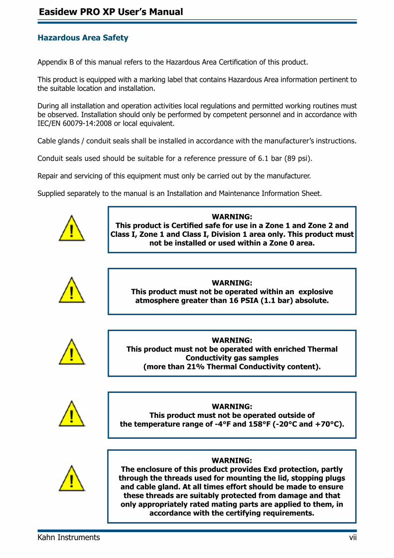
Hazardous Area Safety
AppendixBofthismanualreferstotheHazardousAreaCertificationofthisproduct.
This product is equipped with a marking label that contains Hazardous Area information pertinent to the suitable location and installation.
During all installation and operation activities local regulations and permitted working routines must be observed. Installation should only be performed by competent personnel and in accordance with IEC/EN60079-14:2008orlocalequivalent.
Cableglands/conduitsealsshallbeinstalledinaccordancewiththemanufacturer’sinstructions.
Conduit seals used should be suitable for a reference pressure of 6.1 bar (89 psi).
Repair and servicing of this equipment must only be carried out by the manufacturer.
Supplied separately to the manual is an Installation and Maintenance Information Sheet.
WARNING: This product is Certified safe for use in a Zone 1 and Zone 2 and
Class I, Zone 1 and Class I, Division 1 area only. This product must not be installed or used within a Zone 0 area.
WARNING:This product must not be operated within an explosive atmosphere greater than 16 PSIA (1.1 bar) absolute.
WARNING:This product must not be operated with enriched Thermal
Conductivity gas samples (more than 21% Thermal Conductivity content).
WARNING:This product must not be operated outside of
the temperature range of -4°F and 158°F (-20°C and +70°C).
WARNING:The enclosure of this product provides Exd protection, partly
through the threads used for mounting the lid, stopping plugs and cable gland. At all times effort should be made to ensure these threads are suitably protected from damage and that
only appropriately rated mating parts are applied to them, in accordance with the certifying requirements.

Easidew PRO XP User’s Manual
viii 97442 Issue 2.5, January 2016
Pressure Safety
WARNING:
This product is used in conjunction with pressurized gases. Observe pressurized gas handling precautions.
WARNING:
Pressurized gas is dangerous. Pressurized gas should only handled by suitably trained
personnel.
The Easidew PRO XP requires pressurized gas to be connected to it. Observe pressurized gas handling regulations and only suitable trained personnel should carry out tasks that include the use of pressurized gas.
DO NOT permit pressures greater than the safe working pressure to be applied to the instrument. Thespecifiedsafeworkingpressureforthisinstrumentis6500psig(450barg)max.
Toxic Materials
The use of hazardous materials in the construction of this instrument has been minimized. During normal operation it is not possible for the user to come into contact with any hazardous substance which might be employed in the construction of the instrument. Care should, however, be exercised during maintenance and the disposal of certain parts.
Long exposure to, or breathing of the calibration gases, may be dangerous.
Repair and Maintenance
The instrument must be maintained either by the manufacturer or an accredited service agent. For KahnInstruments’contactinformationgotowww.kahn.com.
Calibration
Prior to shipment, the transmitter undergoes stringent factory calibration to traceable standards. Acalibration certificate traceable toNIST isprovidedwitheach transmitter.Due to the inherentstabilityoftheinstrument,regularfieldcalibrationshouldnotberequiredundernormaloperatingconditions. However, Kahn Instruments recommends that a calibration be considered at intervals of every12monthsoftheinstrument’slife.
Kahn Instruments recommends annual recalibration traceable to NIST. Please contact Kahn Instruments for further details (www.kahn.com).
Otherwise, the transmitter should perform reliably for many years with just basic maintenance and housekeeping.
Safety Conformity
This product carries the CE mark.

Easidew PRO XP User’s Manual
Kahn Instruments ix
Abbreviations
The following abbreviations are used in this manual:
A ampereA/F acrossflatsbarg pressure unit (=100 kP or 0.987 atm) gauge°C degrees Celsius°F degrees Fahrenheitdp dew pointDC direct currentEU European Unionfps feet per secondHDPE high-density polyethyleneins inchesI/O Input/OutputISO International Organization for StandardizationK Kelvin unit of temperature measurementlb/MMSCF poundsofwaterpermillionstandardcubicfeetofgaslb-ft pound footNl/min normallitersperminutem metersmA milliamperemg/m3 milligrams per cubic meter mm millimetermm2 millimeter squaredMpa megapascalm/sec meterspersecondNm Newton meterpcb printed circuit boardpsig pounds per square inch (gauge)ppmV parts per million by volume ppmW parts per million by weightPTFE PolytetrafluoroethyleneRa roughnessaverage(unitofmeasureofsurfacefinish)RH relative humidity scfh standard cubic feet per hourUNF unifiedfinethreadμm micrometer“ inches% percentageV Volts
Easidew PRO XP User’s Manual
Kahn Instruments 1
INTRODUCTION
1 INTRODUCTION
The Easidew PRO XP has been manufactured, tested and calibrated to the highest available standards and should arrive in perfect working order, ready for installation into a gas or liquid measurement application.
For questions about the instrument or how to install and operate it, contact Kahn Instruments (www.kahn.com).
There are two variants of the Easidew PRO XP, each available with various options for display, housing, range, etc:
Easidew PRO XP-TX For gases
Easidew PRO XP-LQ-TX For liquids
1.1 Features
The Easidew PRO XP is a continuous, on-line, 4-20 mA transmitter for the measurement of moisture content in air, other non-corrosive gases and non-polar liquids. It is designed specificallyforusewithinZone1&2andZone21&22HazardousAreas(ATEX&IECEx)andClassI,Division1,GroupsB,C&D,ClassIIandIII,Division1,GroupsE,F&G,ClassI,Zone1&Zone21HazardousLocations(NorthAmerica).
Its key features are:
• Dewpoint measurement range -166 to +68°F (-110 to +20°C)
• Globalexplosion/flameproofcertification
• Accuracy ±1.8°F (±1.0°C)
• 2-wire 4-20 mA output
• Traceable 13-point calibration certificate
• 6500 psig (450 bar) pressure rating
• 3/4”UNFindustrystandardprocessconnection
• EN 10204 3.1 material certification
• Moisture in gases and liquids
• Optional integrated display meter

Easidew PRO XP User’s Manual
2 97442 Issue 2.5, January 2016
INSTALLATION
2 INSTALLATION
2.1 Unpacking the Instrument
On delivery, please check that all the following standard components are present in the packing box:
• Easidew PRO XP Transmitter (EX1 - Non-display OR EX2 - Display)
• Certificateofcalibration
• Quantity two ferrules
• 1.5mmA/FAllenkey
• Quantity 1 conduit entry blanking plug (equipped hand tight)
• User manual
• Installation and maintenance information sheet
• Sample block (optional)
• Pipe mounting bracket (optional)
• EN102043.1materialcertificate(optional)
The Easidew PRO XP is protected within the main packaging with a green cap protecting the sensor guard with a desiccant capsule inside (see Figure 1), and a plastic cap inside the cable entry opening.
Remove and retain these items prior to commissioning.
DO NOT HANDLE THE SENSOR GUARD
Figure 1 Sensor Cap Removal
Easidew PRO XP User’s Manual
Kahn Instruments 3
INSTALLATION
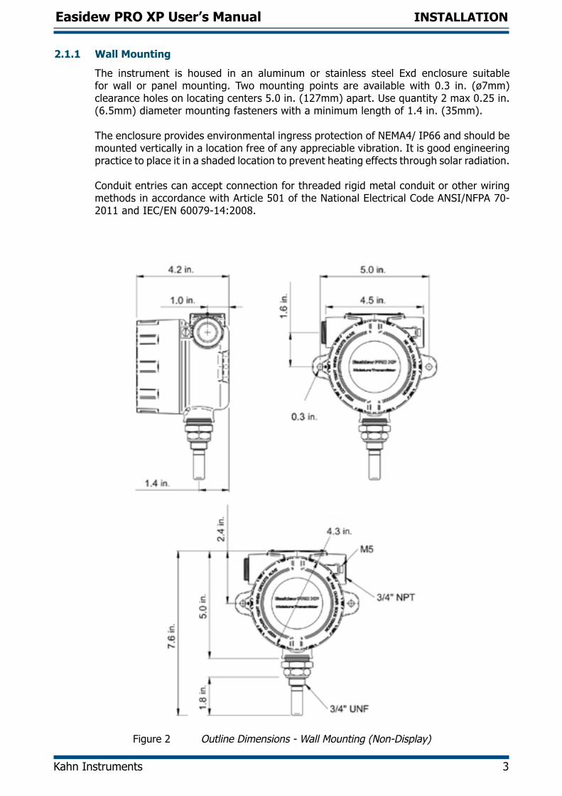
2.1.1 Wall Mounting
The instrument is housed in an aluminum or stainless steel Exd enclosure suitable for wall or panel mounting. Two mounting points are available with 0.3 in. (ø7mm) clearance holes on locating centers 5.0 in. (127mm) apart. Use quantity 2 max 0.25 in. (6.5mm) diameter mounting fasteners with a minimum length of 1.4 in. (35mm).
TheenclosureprovidesenvironmentalingressprotectionofNEMA4/IP66andshouldbemounted vertically in a location free of any appreciable vibration. It is good engineering practice to place it in a shaded location to prevent heating effects through solar radiation.
Conduit entries can accept connection for threaded rigid metal conduit or other wiring methodsinaccordancewithArticle501oftheNationalElectricalCodeANSI/NFPA70-2011andIEC/EN60079-14:2008.
Figure 2 Outline Dimensions - Wall Mounting (Non-Display)

Easidew PRO XP User’s Manual
4 97442 Issue 2.5, January 2016
INSTALLATION
Figure 3 Dimensions Easidew PRO XP EX2 (Display) - Wall Mounting
Easidew PRO XP User’s Manual
Kahn Instruments 5
INSTALLATION
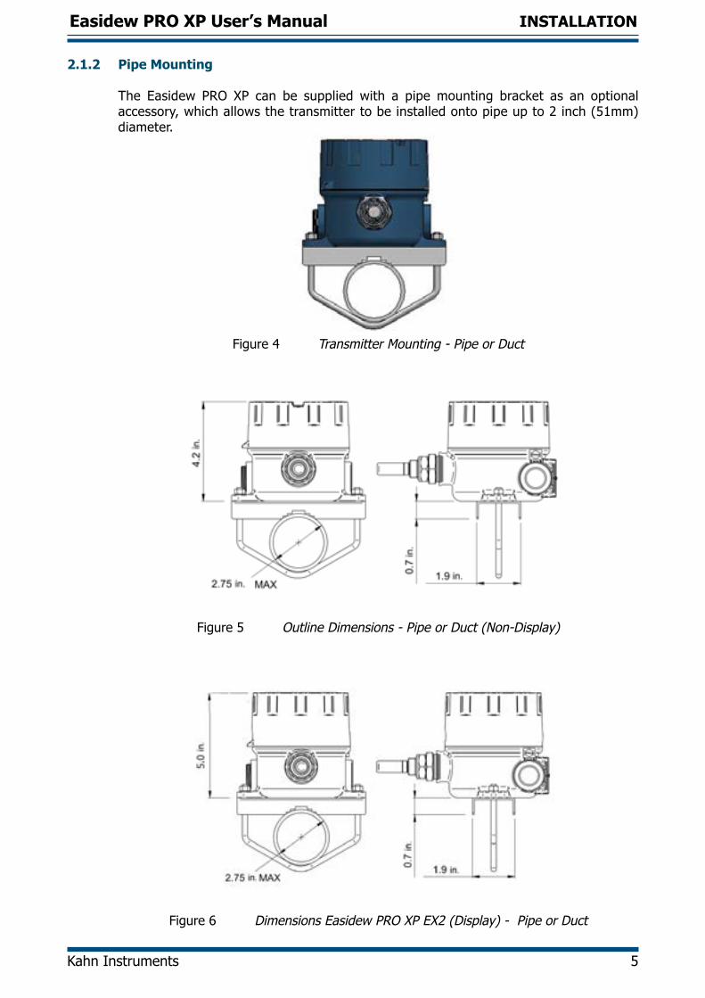
2.1.2 Pipe Mounting
The Easidew PRO XP can be supplied with a pipe mounting bracket as an optional accessory, which allows the transmitter to be installed onto pipe up to 2 inch (51mm) diameter.
Figure 4 Transmitter Mounting - Pipe or Duct
Figure 5 Outline Dimensions - Pipe or Duct (Non-Display)
Figure 6 Dimensions Easidew PRO XP EX2 (Display) - Pipe or Duct
Easidew PRO XP User’s Manual
6 97442 Issue 2.5, January 2016
INSTALLATION
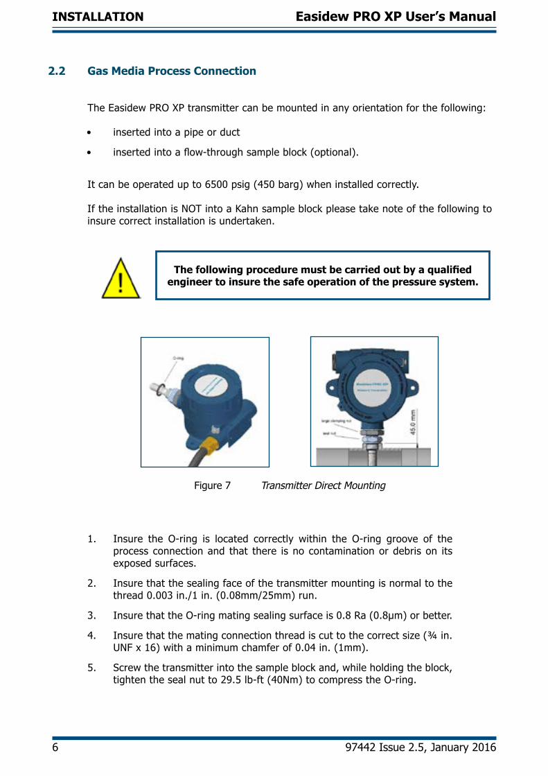
2.2 Gas Media Process Connection
The Easidew PRO XP transmitter can be mounted in any orientation for the following:
• inserted into a pipe or duct
• insertedintoaflow-throughsampleblock(optional).
It can be operated up to 6500 psig (450 barg) when installed correctly.
If the installation is NOT into a Kahn sample block please take note of the following to insure correct installation is undertaken.
The following procedure must be carried out by a qualified engineer to insure the safe operation of the pressure system.
Figure 7 Transmitter Direct Mounting
1. Insure the O-ring is located correctly within the O-ring groove of the process connection and that there is no contamination or debris on its exposed surfaces.
2. Insure that the sealing face of the transmitter mounting is normal to the thread0.003in./1in.(0.08mm/25mm)run.
3. Insure that the O-ring mating sealing surface is 0.8 Ra (0.8µm) or better.
4. Insure that the mating connection thread is cut to the correct size (¾ in. UNF x 16) with a minimum chamfer of 0.04 in. (1mm).
5. Screw the transmitter into the sample block and, while holding the block, tighten the seal nut to 29.5 lb-ft (40Nm) to compress the O-ring.
Easidew PRO XP User’s Manual
Kahn Instruments 7
INSTALLATION
6. Rotate the enclosure to the desired position (up to 360° available) and tighten the large clamping nut 1¼ in. (32mm) to 7.4 lb-ft (10Nm) to insure the dowty seal is correctly compressed for environmental protection (see Appendix B.1).
Therecommendedfluidflowrate,whenmountedintheoptionalsampleblock,is2.1to10.6scfh(1to5l/min).However,fordirectinsertionapplications,theflowcanbefromstaticto32.8fps(10m/sec).
The Easidew PRO XP is fitted with a mechanical stop to prevent the accidental over-rotation of the enclosure assembly that
would damage the internal sensor wiring.
2.3 Liquid Media Process Connection
WhenmountingtheEasidewPROXPintoaliquidsampletheflowratemustbebetween0.2and0.6scfh(0.1and0.3l/min).
Considerationshouldbetakenregardingdrainingthesamplefluidattimeswhenthetransmitter needs to be removed for maintenance or calibration.
ItwouldbebeneficialfortheEasidewPROXPtobemountedinaverticalposition(withthe sensor pointing down) to allow for easy removal when necessary.

Easidew PRO XP User’s Manual
8 97442 Issue 2.5, January 2016
INSTALLATION
2.3.1 Sample Block (Optional)
The following procedure must be carried out by a qualified engineer to insure the safe operation of the pressure system.
1. Remove the green protective cap and desiccant capsule.
2. Insure the O-ring (see Figure 8) is located correctly within the O-ring groove of the process connection and there is no contamination or debris on its exposed surfaces.
3. Screwthetransmitterintothesampleblockand,whileholdingtheflatson the block, tighten the seal nut to 29.5 lb-ft (40Nm) to compress the O-ring.
4. Rotate the enclosure to the desired position (up to 360° available) and tighten the large clamping nut 1¼ in. (32mm) to 7.4 lb-ft (10Nm) to insure the dowty seal is correctly compressed for environmental protection (see Appendix B.1).
Figure 8 Transmitter Mounting - Sample Block
Figure 9 Outline Dimensions - Sample Block

Easidew PRO XP User’s Manual
Kahn Instruments 9
INSTALLATION
2.4 Electrical Schematic
2.4.1 Easidew PRO XP EX1 (Non-Display)
NOTE: To insure compliance with EMC standards, insure that the screen of the power supply/signal cable or the power supply/signal conduit is connected to ground.
With the cable entry option, a conductive cable entry gland is recommended, allowing the transmitter housing to be ground via the cable screen connection.
Always connect the 4-20 mA return signal to a suitable load (see Figure 15) before the power is applied. Without this
connection, the transmitter may be damaged if allowed to operate for prolonged periods.
1 2
3 4
+
-LOADSUPPLY
Screen or Conduit
Figure 10 Electrical Schematic - Easidew PRO XP EX1 (Non-Display)

Easidew PRO XP User’s Manual
10 97442 Issue 2.5, January 2016
INSTALLATION
2.4.2 Easidew PRO XP EX2 (Display)
NOTE: To insure compliance with EMC standards, insure that the screen of the power supply/signal cable or the power supply/signal conduit is connected to ground.
With the cable entry option, a conductive cable entry gland is recommended, allowing the transmitter housing to be ground via the cable screen connection.
Always connect the 4-20 mA return signal to a suitable load (see Figure 16) before the power is applied. Without this
connection, the transmitter may be damaged if allowed to operate for prolonged periods.
+
-LOAD SUPPLY
Screen or Conduit
TRANSMITTER
LOOP POWER
+VE VE-
+VE VE-
From main transmitter pcbBack of display module
Figure 11 Electrical Schematic - Easidew PRO XP EX2 (Display)
2.4.3 Electrical Boundaries
100
200
300
400
500
600
12 14 16 18 20 22 24 26 28
Resi
stan
ce (o
hms)
Supply Voltage
Figure 12 Maximum Load of Easidew PRO XP - Including Cable Resistance
Easidew PRO XP User’s Manual
Kahn Instruments 11
INSTALLATION
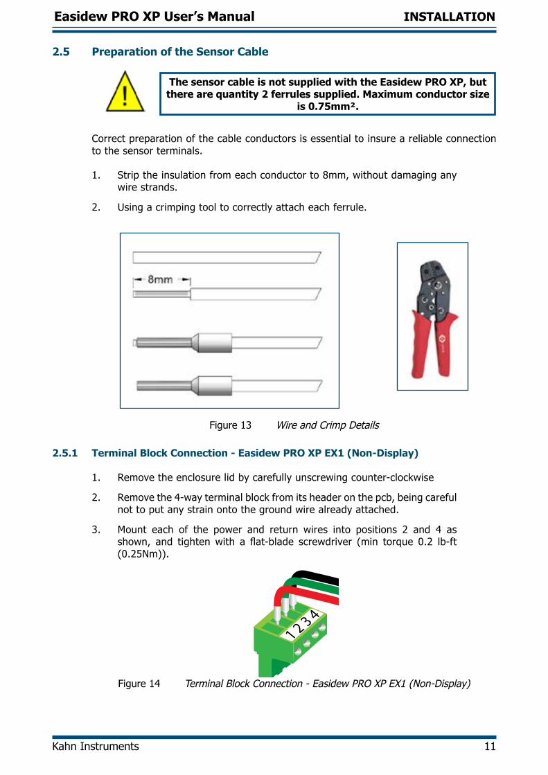
2.5 Preparation of the Sensor Cable
The sensor cable is not supplied with the Easidew PRO XP, but there are quantity 2 ferrules supplied. Maximum conductor size
is 0.75mm².
Correct preparation of the cable conductors is essential to insure a reliable connection to the sensor terminals.
1. Strip the insulation from each conductor to 8mm, without damaging any wire strands.
2. Using a crimping tool to correctly attach each ferrule.
Figure 13 Wire and Crimp Details
2.5.1 Terminal Block Connection - Easidew PRO XP EX1 (Non-Display)
1. Remove the enclosure lid by carefully unscrewing counter-clockwise
2. Remove the 4-way terminal block from its header on the pcb, being careful not to put any strain onto the ground wire already attached.
3. Mount each of the power and return wires into positions 2 and 4 as shown, and tightenwith a flat-blade screwdriver (min torque 0.2 lb-ft (0.25Nm)).
Figure 14 Terminal Block Connection - Easidew PRO XP EX1 (Non-Display)

Easidew PRO XP User’s Manual
12 97442 Issue 2.5, January 2016
INSTALLATION
4. Plug the terminal block back into the header.
5. Reattach the enclosure lid in a clockwise direction until it stops and secure inplacebytighteningthesetscrewwitha1.5mmA/FAllenkey.
Set screw
Figure 15 Set Screw
2.5.2 Terminal Block Connection - Easidew PRO XP EX2 (Display)
1. Remove the enclosure lid by carefully unscrewing counter-clockwise.
2. Lift off the display meter and integral mounting bracket from the 2 mounting posts and pull out the terminal block from the underside.
3. Mount each of the power and return wires into positions +VE and -VE as
shown, and tighten with a straight screwdriver (min torque 0.25Nm).
Figure 16 Terminal Block Mounting - Easidew PRO XP EX2 (Display)
4. Plug the terminal block back into the underside of the display meter and drop it back onto its posts. Align the display meter in relation to the housing, as required.

Easidew PRO XP User’s Manual
Kahn Instruments 13
OPERATION
5. Reattach the enclosure lid in a clockwise direction until it stops and secure inplacebytighteningthesetscrewwitha1.5mmA/FAllenkey.
Set screw
Figure 17 Set Screw

Easidew PRO XP User’s Manual
14 97442 Issue 2.5, January 2016
OPERATION
3 OPERATION
3.1 Measurement and Configuration
TheEasidewPROXPcanbeconfiguredtoprovideanoutputof4-20mA(2-wireconnection)for the following:Dew point -166 to +68°F (-110 to +20°C) Moisture content in gas 0 - 3000 ppmV Moisture content in liquids 0 - 1000 ppmW
TheEasidewPROXPcanbepurchasedfactoryconfiguredasrequired.Alternatively,theEasidewPROXPcanbeconfiguredbythecustomer,usingtheEasidewXPCommunicationsKit (XP-CK) and Easidew Application Software. The Easidew Communications Kit can be purchased from Kahn Instruments. For a free copy of the Application Software contact Kahn Instruments (www.kahn.com).
For moisture content in gas, the calculation from the measured dew point is assumed to beatatmosphericpressure.Alternatively,afixedgaspressureneedstobeprogrammedinto the Easidew PRO XP.
For moisture content measurement in liquid, the Easidew PRO XP requires the saturation constant of the liquid to be programmed into the transmitters, either at the factory or by the customer using the Application Software.
The transmitter requires a 6-point look-up table for saturation constants up to 1000 ppmW over the temperature range +32 to +122°F (0 to +50°C). Saturation constants for 8 common liquids can be programmed into the Easidew PRO XP via the Application Software. Alternatively, the user can program saturation constants manually. The ApplicationSoftwareHelpfileprovidesdetailedinstructionsonhowtoperformthistask.
Easidew PRO XP EX2 (Display) Only
The display meter is simple in design and is a slave display to the measurement and configuration of the main transmitter pcb. It can be scaled linearly equating to thecirculating 4-20 mA signal output from the main transmitter pcb.
Inordertore-configurethedisplay,theenclosurelidshouldberemovedbyunscrewingit in a counter-clockwise direction.
Care should be taken when unscrewing and replacing the enclosure lid as the threads form an important part of the Ex compliance regulations and therefore must not be damaged.
The lid must be replaced after using the display meter and the set screw tightened.
A full explanation of the operation and configuration of the integral display meter isdetailed in Appendix D.

Easidew PRO XP User’s Manual
Kahn Instruments 15
OPERATION
3.2 Sampling Hints
Operation is very simple, assuming the following installation techniques are adhered to:
Be Sure the Sample is Representative of the Gas Under Test:
The sample point should be as close to the critical measurement point as possible. Also, never sample from the bottom of a pipe as entrained liquids may be drawn into the sensing element.
Minimize Dead Space in Sample Lines:
Dead space causes moisture entrapment points, increased system response times and measurement errors, as a result of the trapped moisture being released into the passing sample gas and causing an increase in partial vapor pressure.
Deadspace
Figure 18 Indication of Dead Space
Remove Any Particulate Matter or Oil from the Gas Sample:
Particulate matter at high velocity can damage the sensing element and similarly, at lowvelocity,theymay‘blind’thesensingelementandreduceitsresponsespeed.Ifparticulate, such as degraded desiccant, pipe scale or rust is present in the sample gas, useanin-linefilter,asaminimumlevelofprotection.FormoredemandingapplicationsKahn Instruments offers a range of sampling systems (for more information contact www.kahn.com).
Use High Quality Sample Tube and Fittings:
Kahn Instruments recommends that, wherever possible, stainless steel tubing and fittingsshouldbeused.Thisisparticularlyimportantatlowdewpointssinceothermaterials have hygroscopic characteristics and adsorb moisture on the tubing or pipe walls, slowing down response and, in extreme circumstances, giving false readings. For temporary applications, or where stainless steel tubing is not practical, use high quality thick walled PTFE tubing and work within the maximum pressure rating of this tubing.
Position Transmitter away from Heat Source:
It is recommended, as good instrumentation practice, that the transmitter is placed awayfromanyheatsourcetoavoidadsorption/desorption(particularlysolarradiationduring daylight hours).
Easidew PRO XP User’s Manual
16 97442 Issue 2.5, January 2016
MAINTENANCE
4 MAINTENANCE
!
The power to the enclosure must be turned off before any work is carried out in the measurement system enclosure.
Observe de-energize durations.
Gas line connections to the measurement system must be isolated and de-pressurized before any work commences.
4.1 Calibration
Routinemaintenanceof theEasidewPROXP is confined to regular re-calibrationbyexposure of the transmitter to sample gases of known moisture content to insure that the stated accuracy is maintained. Calibration services traceable to the US National Institute of Standards and Technology (NIST) are provided by Kahn Instruments.
Kahn Instruments offers a re-calibration service to suit specific needs. A Kahnrepresentative can provide detailed, custom advice (for Kahn Instruments’ contactinformation go to www.kahn.com).
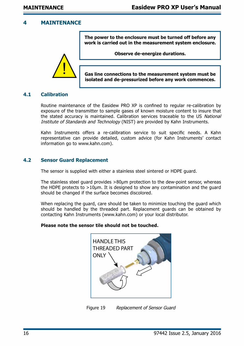
4.2 Sensor Guard Replacement
The sensor is supplied with either a stainless steel sintered or HDPE guard.
Thestainlesssteelguardprovides>80μmprotectiontothedew-pointsensor,whereastheHDPEprotectsto>10μm.Itisdesignedtoshowanycontaminationandtheguardshould be changed if the surface becomes discolored.
When replacing the guard, care should be taken to minimize touching the guard which should be handled by the threaded part. Replacement guards can be obtained by contacting Kahn Instruments (www.kahn.com) or your local distributor.
Please note the sensor tile should not be touched.
HANDLE THIS THREADED PART ONLY
Figure 19 Replacement of Sensor Guard

Easidew PRO XP User’s Manual
Kahn Instruments 17
MAINTENANCE
4.3 Display Replacement
1. Unscrew the locking screw on the enclosure cap with a 1.5mm Allen key.
2. Unscrew the cap, lift the display and mounting ring clear from the 2 off mounting pillars, and unplug the connector.
3. Remove the 2 off small screws holding the display onto its mounting ring.Lift the display clear.
4. Re-assemble as above, in reverse order, being careful not to overtighten the screws. Insure that the connector is fully mated.
5. Re-fittheenclosurecapandtightenthelockingscrew.
6. Thedisplayissuppliedwithadefaultconfiguration.RefertoAppendixD.4‘Re-configurationSteps’ifrequired.

Easidew PRO XP User’s Manual
18 97442 Issue 2.5, January 2016
MAINTENANCE
4.4 O-Ring Replacement
Do not touch the filter with bare hands
1. Identify the O-ring to be removed, as shown below.
BS116 (3/4” x 3/32”) viton, 75 shore
2. Carefully slide tweezers, thin bladed screwdriver or a blunt needle under the outer edge of the O-ring. NOTE: Take care not to scratch any of the surfaces of the surrounding metal component.
3. Move the tool around the circumference to assist the extraction process. SlidetheO-ringclearofthethreadandfilter.
4. Make sure the groove has no scratches and is free from grease, dirt ordebris. Slide thenewO-ringover thefilter and threadand into thegroove. NOTE: Do not touch the filter with bare hands.

Easidew PRO XP User’s Manual
Kahn Instruments 19
APPENDIX A
Appendix A
TechnicalSpecifications

Easidew PRO XP User’s Manual
20 97442 Issue 2.5, January 2016
APPENDIX A
Appendix A Technical Specifications
Product Easidew PRO XP for Gases
Easidew PRO XP LQ for Liquids
Performance Specifications
Measurement Range
-166 to +68°Fdp (-110 to +20°Cdp)
-148 to +68°Fdp (-100 to +20°Cdp)
0 to 1000 ppmWNon-standard available upon
request
Accuracy ±1.8°F (±1°C) dew point +68 to -76°F (+20 to -60°C)±3.6°F (±2°C) dew point -76 to -166°F (-60 to -110°C)
Response Time 5 mins to T95 (dry to wet)
Repeatability ±0.9°Fdp (0.5°Cdp)
Calibration Traceable13-pointcalibrationcertificate
Electrical Specifications
Output Signal 4-20 mA (2-wire connection) current sourceUser-configurableoverrange
Output Dew point or moisture content in ppmV
Moisture content
Analog Output Scaled Range
Dew point -166 to +68°F (-110 to + 20°C)
Moisture content in gas: 0 to 3000 ppmV
Non-standardmg/m3, lbs/MMSCF,naturalgas
Moisture content in liquid: 0 to 1000 ppmW
Non-standard available upon request
Supply Voltage 14 to 28 V DC
Load Resistance Max250Ω@14V(500Ω@24V)
Current Consumption 23 mA (depending on signal output)
Saturation Constants (for moisture in liquids measurements only)
6-point look-up table for saturation constants up to 1000
ppmW over the temperature range +32 to +122°F (0 to
+50°C)Saturation constants for 8 common liquids can be
programmed into the Easidew PRO XP LQ via the Application
SoftwareAlternatively, the user can
program saturation constants manually
Operating SpecificationsOperating Temperature -4 to +158°F (-20 to +70°C)
Operating Pressure 45MPa(6500psig/450barg)max
Flow Rate 2.1to10.6scfh(1to5Nl/min)mountedinstandardsamplingblock0to32.8fps(0to10m/sec)directinsertion
TemperatureCoefficient Temperature compensated across operating temperature range

Easidew PRO XP User’s Manual
Kahn Instruments 21
APPENDIX A
Mechanical Specifications
Ingress Protection IP66 in accordance with standard BS EN 60529:1992NEMA 4 in accordance with standard NEMA 250-2003
Canadian Pressure Vessel Cert C.R.N. - all Canadian provinces
Housing Material
Standard:
Optional:
Aluminum (copper free), epoxy and polyurethane powder coated, blue RAL 5009 316 stainless steel (supplied with BS EN 102043.1materialcertificationifoptionF2requested)ATEX&IECExonly.Stainless steel is not cCSAus approved for N. America
Dimensions Refer to diagram in Section 2.1.1
Filter (Sensor Protection)
Standard:
Optional:
Stainless steel sintered guard (for protection againstfineparticulate>80µm)
HDPEguard(forprotectionagainstfineparticulate >10µm)
ProcessConnection&Material 3/4”-16UNFwithrecessedViton® O-ring316 stainless steel
Weight Aluminum: 3.5lbs (1.6kg)316 stainless steel: 5.3lbs (2.4kg)
Electrical Connections Dual3/4”NPTgland
Display MeterProgrammable Display Range Optional: -1999 to +9999
Programmable Decimal Point Optional: 0 to 3 decimal places
Overload Limits Optional:3.6mA&20.4mA
Programmable Display Scales Optional: °C, °F, %, No scale
Hazardous Area Certification
CertificationCodes(See also Housing Material section above)
ATEX II 2 G D Ex d [ia] IIC T6 Gb Ex tb IIIC T80°C Db IP66 (-20°C to +70°C)IECEx Ex d [ia] IIC T6 Gb Ex tb IIIC T80°C Db IP66 (-20°C to +70°C)INMETRO Ex d [ia] IIC T6 Gb Ex tb IIIC T80°C Db IP66 (-20°C to +70°C)TC TR Ex EX 1 Ex d [ia] IIC T6 Gb X EX tb IIIC T80°C Db X (-20°C to +70°C)cCSAus Class I, Division 1, Groups ABCDClassII&III,Division1,GroupsEFGClassI,Zone1AEx/Exd[ia]IICT6Zone21,AEx/ExtbIIICT80°C

Easidew PRO XP User’s Manual
22 97442 Issue 2.5, January 2016
APPENDIX B
Appendix B
HazardousAreaCertification

Easidew PRO XP User’s Manual
97442 Issue 2, July 2014 23
APPENDIX B
Appendix B Hazardous Area Certification
The EasidewPROXP is certified compliant to theATEXDirective (2014/34/EU)andIECEx for usewithin Zone1&2 andZone21&22HazardousAreas andhas beenassessedsobySIRACertification(NotifiedBody0518).
TheEasidewPROXPiscertifiedcomplianttotheNorthAmericanStandards(USAandCanada)forusewithinClassI,Division1,GroupsA,B,C&D,ClassIIandIII,Division1,GroupsE, F&G,Class I, Zone1& Zone21HazardousLocationsandhasbeenassessed so by cCSAus.
B.1 Product Standards
This product conforms to the Standards:
EN60079-0:2012 IEC 60079-0:2011EN60079-1:2007 IEC 60079-1:2007EN60079-11:2012 IEC 60079-11:2011EN60079-31:2009 IEC 60079-31:2008C22.2No.0-M10 CAN/CSA-C22.2No.60079-0:11C22.2No.25-1966 CAN/CSA-C22.2No.60079-1:11C22.2No.30-M1986 CAN/CSA-C22.2No.60079-11:11C22.2No.142-M1987 CAN/CSA-C22.2No.60079-31:12C22.2 No. 157-92 ISA 60079-0:11FM Class 3600 ISA 60079-1:09FM Class 3610 ISA 60079-11:11FM Class 3615 ISA 60079-31:12FM Class 3616 UL 916-2003
B.2 Product Certification
Thisproductisattributedwiththeproductcertificationcode:
ATEX & IECEx II 2 GD Exd [ia] IIC T6 Gb Ex tb IIIC T80°C Db IP66 (-20°C to +70°C)
North American Class I, Division 1, Groups A,B,C,D
Class II & III, Division 1, Groups E,F,G Class I, Zone 1 AEx/Ex d [ia] IIC T6 Zone 21, AEx/Ex tb IIIC T80°C

Easidew PRO XP User’s Manual
24 97442 Issue 2.5, January 2016
APPENDIX B
B.3 Global Certificates/Approvals ATEX SIRA14ATEX1007XIECEx IECEx SIR 14.0004X cCSAus 2679645INMETRO NCC 14.03240 XTCTREx RUC-GB.ГБ05.В.00833
Thesecertificatescanbeviewedordownloadedfromourwebsiteat:http://www.kahn.com
B.4 Special Conditions
1. The equipment has been assessed with a Um of 28V and shall be installed inaccordancewiththelatestinstallationrequirementsofIEC/EN60079-14forintrinsicallysafeequipmentforEPL“Gb”.
2. The transmitter shall not be installed in such a manner that the sensing probe is in a dust environment.
3. WARNING - POTENTIAL ELECTROSTATIC CHARGING HAZARD. Theequipment must only be wiped with a damp cloth.
4. When installing the transmitter a torque of 10 Nm must be applied to the sensorbody/housingpositioninglocknuttosecureit.Seemanufacturer’sinstructions for further details.
B.5 Maintenance and Installation
TheEasidewPROXPmustonlybeinstalledbysuitablyqualifiedpersonnelandinaccordancewiththeinstructionsprovidedandthetermsoftheapplicableproductcertificates.
Maintenance and servicing of the product must only be carried out by suitably trained personnel or returned to Kahn Instruments.

Easidew PRO XP User’s Manual
Kahn Instruments 25
APPENDIX C
Appendix C
EC Declaration of Conformity

Easidew PRO XP User’s Manual
26 97442 Issue 2.5, January 2016
APPENDIX C
Appendix C EC Declaration of Conformity

Easidew PRO XP User’s Manual
Kahn Instruments 27
APPENDIX D
Appendix D
Fully Programmable Loop Powered 4-Digit LED
Display Meter
Easidew PRO XP User’s Manual
28 97442 Issue 2.5, January 2016
APPENDIX D
Appendix D Fully Programmable Loop Powered 4-Digit LED Display Meter
Inordertore-configurethedisplaymeter,theenclosurelidshouldberemovedbyunscrewingitina counter-clockwise direction.
Care should be taken when unscrewing and replacing the enclosure lid as the threads form an important part of the Ex compliance regulations
and therefore must not be damaged.
The lid must be replaced after using the display meter, and the set screw tightened.
D.1 Display Meter Parameter Limits
The programmable display meter is designed for current loops of 4-20 mA. It is powered from the loopanddoesnotrequireanyothersupply.Thedisplaycanbeconfiguredbyset-upmenustoshowphysical values measured by the sensor.
Display will indicate low (-LO-) when the input current is lower than the overload limit (3.6 mA).
Display will indicate high (-HI-) when the input current is higher than overload limit (20.4 mA).
Display will indicate (----) when displayed value is <1999 or >9999.
D.2 Display Meter Operating Range
Operating Range from 3.6 to 20.4 mAMaximum Voltage Drop Out 3.7 VDisplay LED 4 digits, height 9.5mmIndication Limits from -1999 to 9999Variable Sampling Time from 1 to 10 seconds
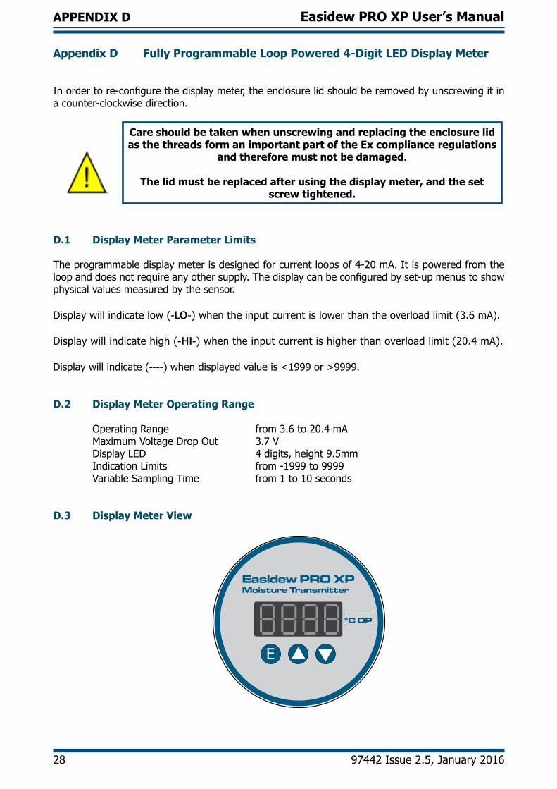
D.3 Display Meter View
E
Easidew PRO XPMoisture Transmitter
°C DP
Easidew PRO XP User’s Manual
Kahn Instruments 29
APPENDIX D
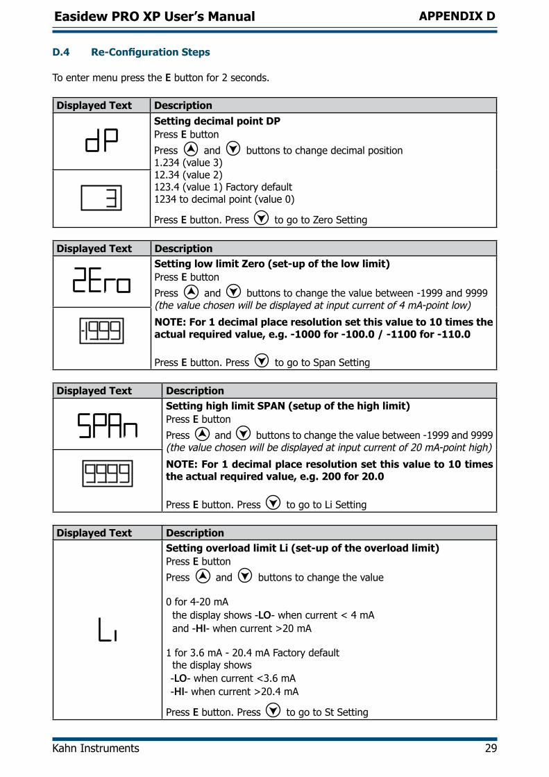
D.4 Re-Configuration Steps
To enter menu press the E button for 2 seconds.
Displayed Text DescriptionSetting decimal point DPPress E button
Press and buttons to change decimal position1.234 (value 3)12.34 (value 2)123.4 (value 1) Factory default1234 to decimal point (value 0)
Press E button. Press togotoZeroSetting Displayed Text Description
Setting low limit Zero (set-up of the low limit)Press E button
Press and buttons to change the value between -1999 and 9999 (the value chosen will be displayed at input current of 4 mA-point low)
NOTE: For 1 decimal place resolution set this value to 10 times the actual required value, e.g. -1000 for -100.0 / -1100 for -110.0
Press E button. Press to go to Span Setting
Displayed Text DescriptionSetting high limit SPAN (setup of the high limit)Press E button
Press and buttons to change the value between -1999 and 9999 (the value chosen will be displayed at input current of 20 mA-point high)
NOTE: For 1 decimal place resolution set this value to 10 times the actual required value, e.g. 200 for 20.0
Press E button. Press to go to Li Setting
Displayed Text DescriptionSetting overload limit Li (set-up of the overload limit)Press E button
Press and buttons to change the value
0 for 4-20 mA the display shows -LO- when current < 4 mA and -HI- when current >20 mA
1 for 3.6 mA - 20.4 mA Factory default the display shows -LO- when current <3.6 mA -HI- when current >20.4 mA
Press E button. Press to go to St Setting

Easidew PRO XP User’s Manual
30 97442 Issue 2.5, January 2016
APPENDIX D
Displayed Text DescriptionSetting sampling rate StPress E button
Press and buttons to change the sampling rate from 1 to 10 seconds1 = Factory default
Press E button. Press to go to Engineering Unit
Displayed Text DescriptionSet-up Engineering UnitPress E button
Press and buttons to select the unit - nonE - for no unit on the display (factory default setting) see D.5 - °C, °F, K, %(There is a 6 second cycle- measured value is displayed for 4 seconds- the unit is displayed for 2 seconds)
Press E button
Exit from menu and save settings:
Press and buttons (possible from each page)
D.5 Moisture Scaling Label
The Easidew PRO XP has 3 standard ranges and scales which are as follows:
EA-XP-TX -110 to +20°Cdp output range -100 to +20°Cdp output range
EA-XP-LQ-TX 0-3000ppmW
TheEA-XP-TXunitswillbeconfiguredfortherange/scaleordered(asabove)andwillconstantlydisplaythemeasuredvalue.Thedisplaymeterwillhaveastick-onlabeldefiningthescalein°CDP.
E
Easidew PRO XPMoisture Transmitter
°C DP
Label
Iforderedwithanon-standardrange/scaletheunitcouldbesetupwiththefollowing:
°F DP lbs/MMSCF ppmV ppmW mg/m3
Alternatively,anEasidewPROXPCommunicationKit(XP-CK)canbeusedtochangetherange/scaleand this Kit will be shipped with its own manual and 2 additional sets of scaling labels so that the label can be changed as required.

Easidew PRO XP User’s Manual
Kahn Instruments 31
APPENDIX D
D.6 Technical Specifications - EX2 LED Display
Thedisplaymeterissimpleindesignandisaslavedisplaytothemeasurementandconfigurationofthe main transmitter pcb. It can be scaled linearly equating to the circulating 4-20 mA signal output from the main transmitter pcb.
+
-LOAD SUPPLY
Screen or Conduit
TRANSMITTER
LOOP POWER
+VE VE-
+VE VE-
From main transmitter pcbBack of display module
PerformanceReference Operating Condition 25°CMaximum Measured Error 0.1% of the programmed range ± 1 digitInfluenceofAmbientTemperature (temp drift) 20ppm/°C of measuring range at 20°C as reference temperature
Output Signal 4-20 mASupply Voltage 24 V (10 to 30 V) Voltage Drop Out 3.3 V at 4 mA and 3.7 V at 20 mAMinimum Current of LED Activation 3.6 mA
Digits LED, 4 digits 7 segments, height 9.5mmDisplay Characteristics 6400ucd for If=10 mAStorage Period 10 years (non-powered)Operating ConditionsAmbient Temperature -4 to +176°F (-20 to +80°C)Storage Temperature -22 to +176°F (-30 to +80°C)FunctionalityParameters Zero,span,decimal,point,refreshrate,unitIndication Limit -1999 to +9999Programmable Range -1999 to +9999Decimal Points Position 0, 1, 2, 3 decimalsOverload Limits From 3.6 to 20.4 mARefresh Rate From 1 to 10 secondsUnit °C, °F, K, % in cycle: 4 second value - 2 second unitMechanical ConstructionElectrical Loop Connection 2 terminals, max wire section 1mm2 (16 AWG)

http://www.kahn.com