high performance optical dewpoint transmitter - kahn · page 3 issue july 2016 kahn instruments,...
TRANSCRIPT

Issue July 2016
KAHN INSTRUMENTS, INC.
885 Wells Road, Wethersfield, CT 06109 Tel: 860-529-8643; Fax: 860-529-1895
Internet: www.kahn.com E-mail: [email protected]
Optidew
High Performance Optical Dewpoint Transmitter
Users Guide

Page 2
Issue July 2016
KAHN INSTRUMENTS, INC.
885 Wells Road, Wethersfield, CT 06109 Tel: 860-529-8643; Fax: 860-529-1895
Internet: www.kahn.com E-mail: [email protected]
Table of Contents
SECTION PAGE
1 Product Overview 3
2 Installation 3 2.1 Electrical Power Supply 4 2.2 Output Connections 5
3 Operation 6 3.1 Dynamic Contamination Correction (DCC) 6 3.2 Data Hold Phase 7
4 Maintenance 9
5 Application Software 10 5.1 Virtual Hygrometer 10 5.2 Parameter Setup 12 5.3 Charting & Logging 13 5.4 Statistics 15 5.5 Control Parameters 15
6 Optidew Display Option 16
6.1 Introduction 16 6.2 Start Up Screen 16 6.3 Switching Between LOCAL and REMOTE Modes 16 6.4 Selecting Which “Screen” to view on the Display 16 6.5 Description of the Various Screens 16
FIGURES
1 Instrument Connections 4 2 Power Connector Wiring 4 3 A Graphical Representation of System Phases 7
4 A Graphical Representation of the Data Hold Phase 8
5 Diagram Showing Location of Potentiometer 9 6 Optidew Display Screen and Navigation 18
7 Optidew Dimensions (Remote Sensor Version) 20
8 Optidew Dimensions (Integral Sensor Version) 21
9 Sensor and Remote Temperature Probe Dimensions 22
10 Display Remote and Integral Versions Dimensions 23
APPENDIX
A Technical Specification 19
Page 3
Issue July 2016
KAHN INSTRUMENTS, INC.
885 Wells Road, Wethersfield, CT 06109 Tel: 860-529-8643; Fax: 860-529-1895
Internet: www.kahn.com E-mail: [email protected]
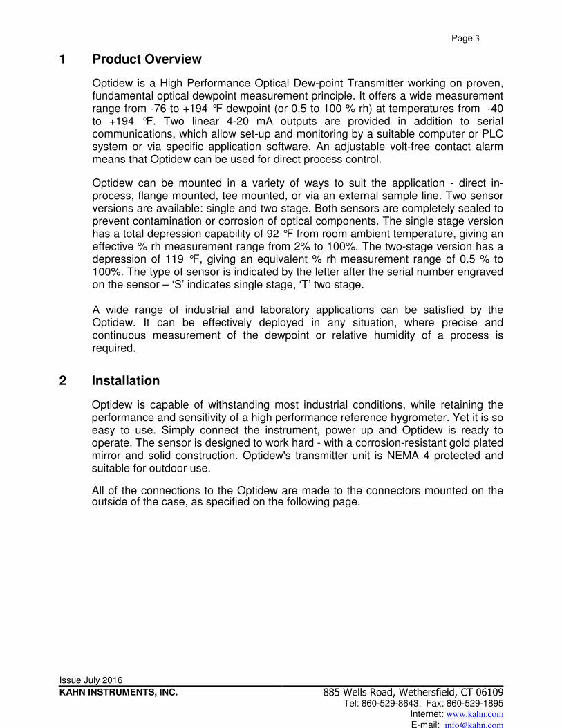
1 Product Overview
Optidew is a High Performance Optical Dew-point Transmitter working on proven, fundamental optical dewpoint measurement principle. It offers a wide measurement range from -76 to +194 °F dewpoint (or 0.5 to 100 % rh) at temperatures from -40 to +194 °F. Two linear 4-20 mA outputs are provided in addition to serial communications, which allow set-up and monitoring by a suitable computer or PLC system or via specific application software. An adjustable volt-free contact alarm means that Optidew can be used for direct process control.
Optidew can be mounted in a variety of ways to suit the application - direct in-process, flange mounted, tee mounted, or via an external sample line. Two sensor versions are available: single and two stage. Both sensors are completely sealed to prevent contamination or corrosion of optical components. The single stage version has a total depression capability of 92 °F from room ambient temperature, giving an effective % rh measurement range from 2% to 100%. The two-stage version has a depression of 119 °F, giving an equivalent % rh measurement range of 0.5 % to 100%. The type of sensor is indicated by the letter after the serial number engraved on the sensor – ‘S’ indicates single stage, ‘T’ two stage. A wide range of industrial and laboratory applications can be satisfied by the Optidew. It can be effectively deployed in any situation, where precise and continuous measurement of the dewpoint or relative humidity of a process is required.
2 Installation
Optidew is capable of withstanding most industrial conditions, while retaining the performance and sensitivity of a high performance reference hygrometer. Yet it is so easy to use. Simply connect the instrument, power up and Optidew is ready to operate. The sensor is designed to work hard - with a corrosion-resistant gold plated mirror and solid construction. Optidew's transmitter unit is NEMA 4 protected and suitable for outdoor use.
All of the connections to the Optidew are made to the connectors mounted on the outside of the case, as specified on the following page.
Page 4
Issue July 2016
KAHN INSTRUMENTS, INC.
885 Wells Road, Wethersfield, CT 06109 Tel: 860-529-8643; Fax: 860-529-1895
Internet: www.kahn.com E-mail: [email protected]
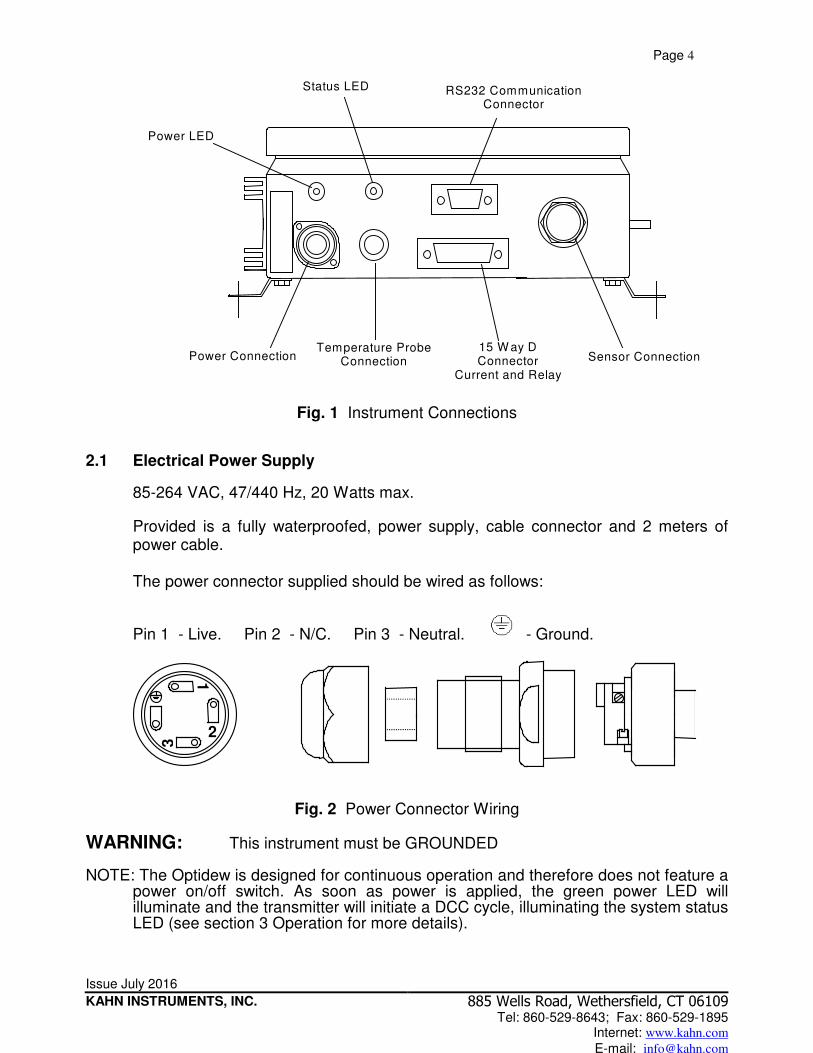
Power LED
Status LED RS232 Communication Connector
Power Connection Temperature Probe
Connection 15 W ay D Connector
Current and Relay Outputs
Sensor Connection
Fig. 1 Instrument Connections 2.1 Electrical Power Supply
85-264 VAC, 47/440 Hz, 20 Watts max. Provided is a fully waterproofed, power supply, cable connector and 2 meters of power cable. The power connector supplied should be wired as follows:
Pin 1 - Live. Pin 2 - N/C. Pin 3 - Neutral. - Ground.
1
2
3
Fig. 2 Power Connector Wiring
WARNING: This instrument must be GROUNDED NOTE: The Optidew is designed for continuous operation and therefore does not feature a
power on/off switch. As soon as power is applied, the green power LED will illuminate and the transmitter will initiate a DCC cycle, illuminating the system status LED (see section 3 Operation for more details).

Page 5
Issue July 2016
KAHN INSTRUMENTS, INC.
885 Wells Road, Wethersfield, CT 06109 Tel: 860-529-8643; Fax: 860-529-1895
Internet: www.kahn.com E-mail: [email protected]
2.2 Output Connections
Current Outputs The Optidew provides two current outputs, which can be set to either 4-20 or 0-20 mA and scaled by the user over the range –200 to +1000 by use of the supplied application software (see section 5.2 Parameter setup for more details). The Channel1 mA output can be set for dewpoint, % rh, gm-3, gkg-1, temperature, or ∆(t - tdp). Channel2 outputs temperature only. The connections for both of these outputs is via the 15-way ‘D’ type connector: mA Output 15 way D type Pin
connection Channel1- dewpoint, % rh, gm-3, gkg-1, temperature, ∆(t - tdp)
Pin 1
Channel1 0 V Pin 2 Channel2 temperature Pin 3 Channel2 0 V Pin 4 Relay Outputs
There are two sets of relay outputs available via the 15-way D type connector. They are the optics fault/alarm relay and a status relay. The optics fault/alarm relay changes state either to indicate that the sensor mirror and optics require cleaning (the red status led will flash to provide a visual indication of this fault) or when the process variable exceeds the alarm set-point value (no visual indication).
The status relay changes state when the instrument is in DCC (Dynamic Contamination Control), Data Hold, or if the system has an optics fault.
Output 15 way D type Pin connection Optics Fault / Alarm Relay N/O Pin 9 Optics Fault / Alarm Relay COM Pin 10 Optics Fault / Alarm Relay N/C Pin 11 Status Relay N/O Pin 12 Status Relay COM Pin 13 Status Relay N/C Pin 14
Communications Port The 9 way ‘D’ connector is used to communicate with the Optidew via the application software, or by an ASCII terminal program. The communication interface is RS232 as standard or RS485 as a factory settable option.
Pin No. RS232 RS485 2 Tx B 3 Rx A 5 GND GND

Page 6
Issue July 2016
KAHN INSTRUMENTS, INC.
885 Wells Road, Wethersfield, CT 06109 Tel: 860-529-8643; Fax: 860-529-1895
Internet: www.kahn.com E-mail: [email protected]
Remote Temperature Probe The temperature probe is supplied pre-wired and simply needs to be fitted to the connector on the Optidew prior to use. Power LED - Indicates power to the Optidew. Status LED - If the status led is permanently lit it indicates that the instrument is either in DCC (Dynamic Contamination Control) or Data Hold mode. If the LED is flashing it indicates an optics fault. RS232 Communications - The 9-way ‘D’ connector is used to communicate with the Optidew via the application software or an ASCII terminal program. Sensor Connection - The Optidew sensor is fitted to a bayonet type connector either directly onto the case for the integral sensor configuration, or via a sensor cable for the remote sensor configuration. Integral sensor removal – The sensor, when in the integral configuration, is supported by a bracket mounted on the side of the Optidew case. In order to remove the sensor, first loosen the nut holding the bracket in place (see Appendix C Integral Sensor Configuration drawing for more details). The sensor connector can now be twisted counterclockwise to release it and can be removed completely with the bracket attached. To remove the bracket from the sensor first remove the sintered guard, if fitted, and then release the locking nut.
3 Operation
3.1 Dynamic Contamination Correction (DCC)
To alleviate the problems of measurement accuracy due to contamination, the Optidew employs a totally new contamination compensation system. Dynamic Contamination Correction (DCC) automatically eliminates any error that may be caused by mirror particulate contamination. DCC is a self-learning system that adapts itself to operating conditions, predicts and reacts to the real requirements for contamination correction to achieve optimum transmitter performance at all times. Although the DCC system is fully automatic, it can be user configured to accommodate your own process conditions. As further protection in extreme conditions, sintered stainless steel or porous membrane guard options are available. Either guard can also be used as a flow limiter in high velocity direct insertion applications.
At switch-on the Optidew will enter DCC, illuminate the Status LED and energize the Status Relay. During this phase, the mirror surface is heated above the ambient dewpoint to measure mirror contamination, while Channel1 mA output is held at 23 mA until the system has made a measurement. The next time Optidew enters DCC, this output will be held at a level equivalent to the measured value before DCC is started.
Page 7
Issue July 2016
KAHN INSTRUMENTS, INC.
885 Wells Road, Wethersfield, CT 06109 Tel: 860-529-8643; Fax: 860-529-1895
Internet: www.kahn.com E-mail: [email protected]
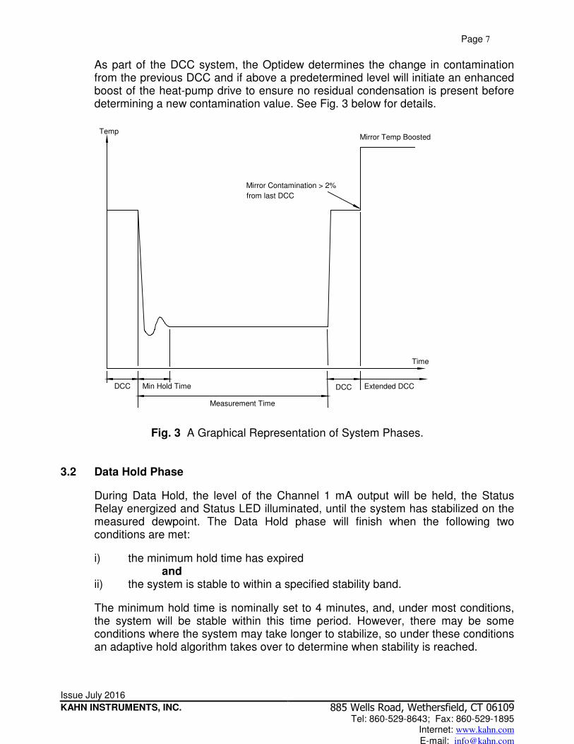
As part of the DCC system, the Optidew determines the change in contamination from the previous DCC and if above a predetermined level will initiate an enhanced boost of the heat-pump drive to ensure no residual condensation is present before determining a new contamination value. See Fig. 3 below for details.
DCC Min Hold Time
Measurement Time
DCC
Time
Temp
Extended DCC
Mirror Contamination > 2%
from last DCC
Mirror Temp Boosted
Fig. 3 A Graphical Representation of System Phases.
3.2 Data Hold Phase
During Data Hold, the level of the Channel 1 mA output will be held, the Status Relay energized and Status LED illuminated, until the system has stabilized on the measured dewpoint. The Data Hold phase will finish when the following two conditions are met:
i) the minimum hold time has expired and
ii) the system is stable to within a specified stability band.
The minimum hold time is nominally set to 4 minutes, and, under most conditions, the system will be stable within this time period. However, there may be some conditions where the system may take longer to stabilize, so under these conditions an adaptive hold algorithm takes over to determine when stability is reached.

Page 8
Issue July 2016
KAHN INSTRUMENTS, INC.
885 Wells Road, Wethersfield, CT 06109 Tel: 860-529-8643; Fax: 860-529-1895
Internet: www.kahn.com E-mail: [email protected]
If under extreme conditions the system fails to stabilize to within the set stability band, the Data Hold phase will terminate when the maximum hold time is reached. When the Data Hold finishes, the Status LED will turn off, the Status Relay will de-energize, and Channel 1 mA output will be set to a value, which represents the measured value of the selected measurement parameter. The system will now be in its continuous measurement phase, where it will remain until the measurement time has elapsed and the next DCC cycle initiates.
Temp
DCC Min Hold
Time
Adaptive Hold
Time
Hold On Analogue O/P Released
Fig.4 A Graphical Representation of the Data Hold Phase.

Page 9
Issue July 2016
KAHN INSTRUMENTS, INC.
885 Wells Road, Wethersfield, CT 06109 Tel: 860-529-8643; Fax: 860-529-1895
Internet: www.kahn.com E-mail: [email protected]
4 Maintenance
Your Optidew instrument will arrive ready for operation. However, throughout the life of the instrument, periodic cleaning of the mirror surface and optics window may be required, depending upon operational conditions and exposure of the sensor to contamination. Sensor cleaning is mandatory if the instrument indicates an optics fault. The cleaning procedure is as follows: a) Switch the instrument off and remove the guard (if installed) from the sensor,
or the sensor from its sampling point in the case of a remote version. b) Clean the mirror surface and optics window with a “Q-Tip” soaked in distilled
water. If the sensor has been exposed to oil based contamination, then use one of the following solvents: methanol, ethanol, or isopropyl alcohol.
a) When cleaning is complete, switch the instrument on and observe the mirror
contamination value during the DCC phase. If this value is not 0 %, then remove the lid of the case and adjust the potentiometer until this value is reached, ensuring that the adjustments are made ONLY during the DCC phase. If this value is under-range, the display will flash 0 %, indicating that a positive adjustment is required.
Note: There will be a delay of approx 5 seconds between the actual adjustment and the displayed value changing.
Pote
ntiom
ete
r
Fig.5 Diagram Showing Location of Potentiometer.

Page 10
Issue July 2016
KAHN INSTRUMENTS, INC.
885 Wells Road, Wethersfield, CT 06109 Tel: 860-529-8643; Fax: 860-529-1895
Internet: www.kahn.com E-mail: [email protected]
5 Application Software
The application software is an interface to the Optidew that provides a display of the measured and calculated parameters, system status, charting and logging, statistical information, and a facility to view and change the system parameters.
5.1 Virtual Hygrometer
The virtual hygrometer window provides a display for the instrument by showing the measured parameters and status.
The humidity display has the ability to display dewpoint (°C/°F), % rh, gm-3, gkg-1, ∆(t – tdp), or aw by pressing the ‘Change Units’ button. Selecting one of these options will show the measured or calculated value, but will not change the Channel 1 mA output of the instrument, as this can only be done via the parameter setup window, see section 5.2. When the software is executed, it will default to the present setting of Channel 1 mA output. The ambient temperature is constantly shown in the lower display. The Peltier Power indicates how much the heat-pump is depressing in order to measure the dewpoint. When the Peltier Power has a value of 100 % and does not reduce over an extended period of time, it means that the heat pump is at maximum depression. In normal operation this indicates that the dewpoint is lower than the present mirror temp and therefore cannot be measured. Reducing the sensor ambient temperature by use of additional cooling will increase the measurement range of the instrument in applications where the Peltier power > 95 %.
Page 11
Issue July 2016
KAHN INSTRUMENTS, INC.
885 Wells Road, Wethersfield, CT 06109 Tel: 860-529-8643; Fax: 860-529-1895
Internet: www.kahn.com E-mail: [email protected]
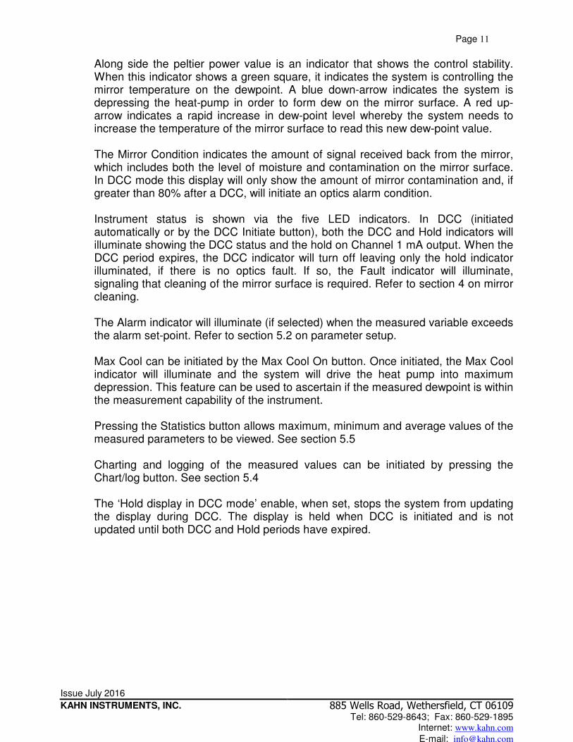
Along side the peltier power value is an indicator that shows the control stability. When this indicator shows a green square, it indicates the system is controlling the mirror temperature on the dewpoint. A blue down-arrow indicates the system is depressing the heat-pump in order to form dew on the mirror surface. A red up-arrow indicates a rapid increase in dew-point level whereby the system needs to increase the temperature of the mirror surface to read this new dew-point value. The Mirror Condition indicates the amount of signal received back from the mirror, which includes both the level of moisture and contamination on the mirror surface. In DCC mode this display will only show the amount of mirror contamination and, if greater than 80% after a DCC, will initiate an optics alarm condition. Instrument status is shown via the five LED indicators. In DCC (initiated automatically or by the DCC Initiate button), both the DCC and Hold indicators will illuminate showing the DCC status and the hold on Channel 1 mA output. When the DCC period expires, the DCC indicator will turn off leaving only the hold indicator illuminated, if there is no optics fault. If so, the Fault indicator will illuminate, signaling that cleaning of the mirror surface is required. Refer to section 4 on mirror cleaning. The Alarm indicator will illuminate (if selected) when the measured variable exceeds the alarm set-point. Refer to section 5.2 on parameter setup. Max Cool can be initiated by the Max Cool On button. Once initiated, the Max Cool indicator will illuminate and the system will drive the heat pump into maximum depression. This feature can be used to ascertain if the measured dewpoint is within the measurement capability of the instrument. Pressing the Statistics button allows maximum, minimum and average values of the measured parameters to be viewed. See section 5.5 Charting and logging of the measured values can be initiated by pressing the Chart/log button. See section 5.4 The ‘Hold display in DCC mode’ enable, when set, stops the system from updating the display during DCC. The display is held when DCC is initiated and is not updated until both DCC and Hold periods have expired.
Page 12
Issue July 2016
KAHN INSTRUMENTS, INC.
885 Wells Road, Wethersfield, CT 06109 Tel: 860-529-8643; Fax: 860-529-1895
Internet: www.kahn.com E-mail: [email protected]
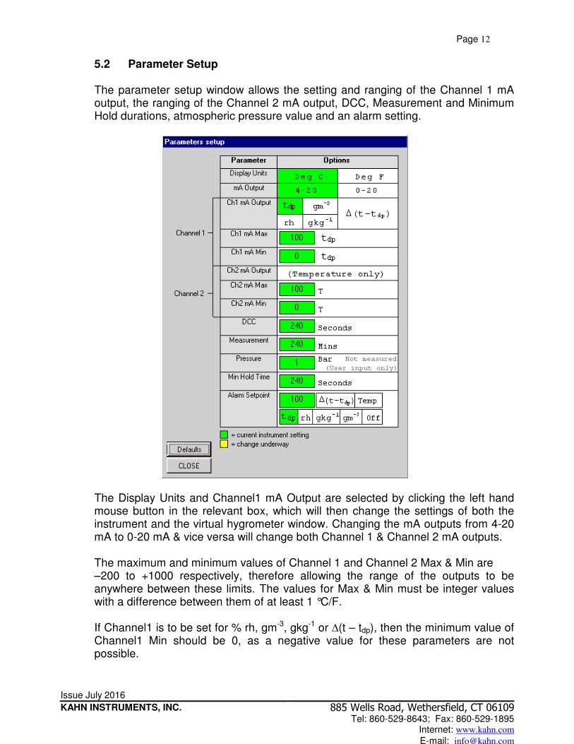
5.2 Parameter Setup The parameter setup window allows the setting and ranging of the Channel 1 mA output, the ranging of the Channel 2 mA output, DCC, Measurement and Minimum Hold durations, atmospheric pressure value and an alarm setting.
The Display Units and Channel1 mA Output are selected by clicking the left hand mouse button in the relevant box, which will then change the settings of both the instrument and the virtual hygrometer window. Changing the mA outputs from 4-20 mA to 0-20 mA & vice versa will change both Channel 1 & Channel 2 mA outputs. The maximum and minimum values of Channel 1 and Channel 2 Max & Min are –200 to +1000 respectively, therefore allowing the range of the outputs to be anywhere between these limits. The values for Max & Min must be integer values with a difference between them of at least 1 °C/F. If Channel1 is to be set for % rh, gm-3, gkg-1 or ∆(t – tdp), then the minimum value of Channel1 Min should be 0, as a negative value for these parameters are not possible.

Page 13
Issue July 2016
KAHN INSTRUMENTS, INC.
885 Wells Road, Wethersfield, CT 06109 Tel: 860-529-8643; Fax: 860-529-1895
Internet: www.kahn.com E-mail: [email protected]
The pressure value is to correct gm-3 and gkg-1 for atmospheric pressure. By entering the atmospheric pressure the display and Channel 1 mA output (if either gm-3 or gkg-1 is selected) will both be corrected accordingly. The Alarm can be set to OFF or set to be active on any of the process variables i.e. dewpoint, ambient temperature, temperature difference, % rh, gm-3, or gkg-1 as shown above. The set-point needs to be an integer value between –200 and +1000, although negative set-points are only valid for dewpoint and ambient temperature. If the process variable exceeds the set-point, the Alarm indicator on the virtual hygrometer will illuminate and the Optics Fault/Alarm relay will change state. To change any of the values, enter the required value and press the return key. The background of the text box will change to yellow to indicate that the change is taking place. When confirmation has been received that the instrument has accepted the change, the background will change back to green. NOTE: When the Parameter Setup window is open, the values in the Virtual Hygrometer window are frozen. The Parameter Setup window needs to be closed for the software to resume normal display mode.
5.3 Charting and Logging
Pressing the Chart/log button on the virtual hygrometer brings up the chart / log panel window.
The chart in its default configuration displays dewpoint, temperature and % rh. However, gm-3, gkg-1 and ∆(t – tdp), can be added by ticking the appropriate check box.

Page 14
Issue July 2016
KAHN INSTRUMENTS, INC.
885 Wells Road, Wethersfield, CT 06109 Tel: 860-529-8643; Fax: 860-529-1895
Internet: www.kahn.com E-mail: [email protected]
Within the Global group box, you can select the charting and logging interval from a minimum of 5 seconds to a maximum of 1 hour. It offers the facility to log the temperature of the mirror while in DCC and Hold, or hold the measured value while in these modes and chart the held data values accordingly. To log the measured and calculated humidity values to a data file for further analysis, tick the check box in the Logging group box and specify a file name by pressing the Browse button. If a log file is not required simply uncheck the box. To Run, Pause and Stop, the charting and logging facility use the chart control buttons accordingly. Pressing the Run button will bring up the chart as shown below. The chart shows the measured and calculated humidity values selected in the chart group box, with an assigned identifiable colour for each value. It is possible to scale, zoom and scroll both X and Y axis of the chart by using the controls in the chart settings window, which can be activated by pressing the Chart Settings button on the charting window.
The X & Y axes can be individually scaled. The X-axis can be scaled by using the Zoom X feature, while the Y-axis can be scaled by changing the min and max values, or selecting a parameter in the auto-scale list, which scales the Y-axis to the actual values of the parameter. There are a number of modes associated with the chart, which can be selected by the chart mode list; Plot, Scroll X,Y, & XY, Cursor, Zoom X,Y, & XY and Zoom Box. In order to use the scrolling and zooming modes, make your selection and press the

Page 15
Issue July 2016
KAHN INSTRUMENTS, INC.
885 Wells Road, Wethersfield, CT 06109 Tel: 860-529-8643; Fax: 860-529-1895
Internet: www.kahn.com E-mail: [email protected]
left mouse button on the chart itself, moving the mouse across the chart accordingly with the left mouse button held down. This will zoom or scroll the chart accordingly. Individual data points can be selected from the chart by using the cursor mode. Select the parameter in question by clicking on a legend on the right hand side of the chart (°C dewpoint is shown as selected above) and moving the cursor to the point of interest; the actual value with its time stamp will be displayed above the chart.
5.4 Statistics
Pressing the Statistics button on the virtual hygrometer window will display the statistics window as shown:
This shows the maximum, minimum and average of each parameter since the program began taking readings from the instrument, or since the reset button was pressed.
5.5 Control Parameters
The control parameters should only be amended by trained personnel in order to adjust the system for operation in extreme conditions. Contact Kahn Instruments for details.
Page 16
Issue July 2016
KAHN INSTRUMENTS, INC.
885 Wells Road, Wethersfield, CT 06109 Tel: 860-529-8643; Fax: 860-529-1895
Internet: www.kahn.com E-mail: [email protected]
6 Optidew Display Option
6.1 Introduction
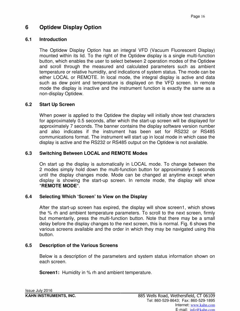
The Optidew Display Option has an integral VFD (Vacuum Fluorescent Display) mounted within its lid. To the right of the Optidew display is a single multi-function button, which enables the user to select between 2 operation modes of the Optidew and scroll through the measured and calculated parameters such as ambient temperature or relative humidity, and indications of system status. The mode can be either LOCAL or REMOTE. In local mode, the integral display is active and data such as dew point and temperature is displayed on the VFD screen. In remote mode the display is inactive and the instrument function is exactly the same as a non-display Optidew.
6.2 Start Up Screen
When power is applied to the Optidew the display will initially show test characters for approximately 0.5 seconds, after which the start-up screen will be displayed for approximately 7 seconds. The banner contains the display software version number and also indicates if the instrument has been set for RS232 or RS485 communications format. The instrument will start up in local mode in which case the display is active and the RS232 or RS485 output on the Optidew is not available.
6.3 Switching Between LOCAL and REMOTE Modes
On start up the display is automatically in LOCAL mode. To change between the 2 modes simply hold down the multi-function button for approximately 5 seconds until the display changes mode. Mode can be changed at anytime except when display is showing the start-up screen. In remote mode, the display will show *REMOTE MODE*.
6.4 Selecting Which ‘Screen’ to View on the Display
After the start-up screen has expired, the display will show screen1, which shows the % rh and ambient temperature parameters. To scroll to the next screen, firmly but momentarily, press the multi-function button. Note that there may be a small delay before the display changes to the next screen, this is normal. Fig. 6 shows the various screens available and the order in which they may be navigated using this button.
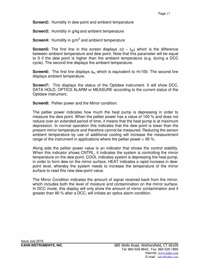
6.5 Description of the Various Screens
Below is a description of the parameters and system status information shown on each screen.
Screen1: Humidity in % rh and ambient temperature.
Page 17
Issue July 2016
KAHN INSTRUMENTS, INC.
885 Wells Road, Wethersfield, CT 06109 Tel: 860-529-8643; Fax: 860-529-1895
Internet: www.kahn.com E-mail: [email protected]
Screen2: Humidity in dew point and ambient temperature
Screen3: Humidity in g/kg and ambient temperature
Screen4: Humidity in g/m3 and ambient temperature
Screen5: The first line in this screen displays ∆(t – tdp) which is the difference between ambient temperature and dew point. Note that this parameter will be equal to 0 if the dew point is higher than the ambient temperature (e.g. during a DCC cycle). The second line displays the ambient temperature.
Screen6: The first line displays aw, which is equivalent to rh/100. The second line displays ambient temperature.
Screen7: This displays the status of the Optidew instrument. It will show DCC, DATA HOLD, OPTICS ALARM or MEASURE according to the current status of the Optidew instrument.
Screen8: Peltier power and the Mirror condition.
The peltier power indicates how much the heat pump is depressing in order to measure the dew point. When the peltier power has a value of 100 % and does not reduce over an extended period of time, it means that the heat pump is at maximum depression. In normal operation this indicates that the dew point is lower than the present mirror temperature and therefore cannot be measured. Reducing the sensor ambient temperature by use of additional cooling will increase the measurement range of the instrument in applications where the peltier power > 95 %. Along side the peltier power value is an indicator that shows the control stability. When this indicator shows CNTRL, it indicates the system is controlling the mirror temperature on the dew point. COOL indicates system is depressing the heat pump, in order to form dew on the mirror surface. HEAT indicates a rapid increase in dew-point level, whereby the system needs to increase the temperature of the mirror surface to read this new dew-point value. The Mirror Condition indicates the amount of signal received back from the mirror, which includes both the level of moisture and contamination on the mirror surface. In DCC mode, this display will only show the amount of mirror contamination and if greater than 80 % after a DCC, will initiate an optics alarm condition.

Page 18
Issue July 2016
KAHN INSTRUMENTS, INC.
885 Wells Road, Wethersfield, CT 06109 Tel: 860-529-8643; Fax: 860-529-1895
Internet: www.kahn.com E-mail: [email protected]
Apply Power
Optidew Transmitter
Display Ver 1.0 232
rh 49.7 %
t 10.0 ºC
tdp 0.0 ºC
t 10.0 ºC
Y 106.00 gkg-1
t 10.0 ºC
dv 106.00 gm-3
t 10.0 ºC
(t-tdp) 10.0 ºC
t 10.0 ºC
aw 0.5
t 10.0 ºC
Status=MEASURE
Mirror: 50 %
Peltier: 40 % COOL
Start up screen
Screen 1
Screen 2
Screen 3
Screen 4
Screen 5
Screen 6
Screen 7
Screen 8
Fig 6. Optidew Display Screens and Navigation.

Page 19
Issue July 2016
KAHN INSTRUMENTS, INC.
885 Wells Road, Wethersfield, CT 06109 Tel: 860-529-8643; Fax: 860-529-1895
Internet: www.kahn.com E-mail: [email protected]
APPENDIX A Optidew Technical Specification
General
Overall Accuracy ±0.36 °F (±0.2°C) dewpoint Measurement Units dewpoint (°F/°C), % rh, temperature (°F/°C), g/m3, g/kg Response Speed 1.8 °F/sec Power Supply 90 to 264 V, 47/440 Hz, 20 W. Internally fused, 4A quick
blow. Sensor Single Stage Dual Stage Dew-point range -58 to +194 °F -76 to +194 °F Temp range -40 to +194 °F -40 to +194 °F rh range 2 to 100 % 0.5 to 100 % Depression @ 70 °F -22 °F -49 °F ambient Mirror Gold plated copper
Temp Measurement 4 wire 100 Ω platinum resistance thermometer Sample Flow 0.2 to 4 SCFH (in sampling block) Max Velocity 32.8 ft./sec. (direct insertion)
98.4 ft./sec. (with sintered guard) Pressure 3000 PSI (max) Cable length 825 feet (max) Electronics
Repeatability ±0.18°F (±0.1°C) Resolution 0.18 °F Outputs Analog: 4-20 mA or 0-20 mA over user settable output;
Accuracy ±0.9 °C, 500 Ω maximum load resistance. Digital: RS232 @ 9600 baud rate. alarm: dry contact, 2A @ 30 V dc, 0.5 A @ 120 V ac LED: Status/Optics Alarm Operating Temp -4 to +104 °F Environmental Conditions Up to 98 % rh non-condensing, 100 % rh condensing
with optional weatherproof cable pack. Enclosure 304 stainless steel (DIN 1.4301) Ingress protection NEMA 4 Cable Pack Power, RS232 cable and output connector. Options i) Remote sensor, cable length up to 825 feet (6 feet standard). ii) Sintered stainless steel sensor guard. iii) HDPE sensor guard. iv) Weather proof pack. v) RS485 digital communications. vi) Sensor locking unit. vii) Integral Display (2 x 20 character, vacuum placement).

Page 20
Issue July 2016
KAHN INSTRUMENTS, INC.
885 Wells Road, Wethersfield, CT 06109 Tel: 860-529-8643; Fax: 860-529-1895
Internet: www.kahn.com E-mail: [email protected]
Fig. 7 Optidew Dimensions (Remote Sensor Version).
200
90
Wall Mounting Brackets - 4 Off Ø M8
200 164
222

Page 21
Issue July 2016
KAHN INSTRUMENTS, INC.
885 Wells Road, Wethersfield, CT 06109 Tel: 860-529-8643; Fax: 860-529-1895
Internet: www.kahn.com E-mail: [email protected]
Fig. 8 Optidew Dimensions (Integral Sensor Version).
222 Wall Mounting Brackets - 4 Off Ø M8
164
365
90
200
200
Bracket Retaining Nut

Page 22
Issue July 2016
KAHN INSTRUMENTS, INC.
885 Wells Road, Wethersfield, CT 06109 Tel: 860-529-8643; Fax: 860-529-1895
Internet: www.kahn.com E-mail: [email protected]
Fig. 9 Sensor and Remote Temperature Probe Dimensions
Ø28
M36X1.5-6g
74
With Sintered Guard (Optional)
63 (2 Stage)
61 (1 Stage)
126 (1 Stage)
128 (2 Stage)
Ø45
Sensor Overall Dimensions
Ø3 CABLE DIAMETER
Ø 4.7 70
79 30
Ø10
Remote Temperature Probe Dimensions

Page 23
Issue July 2016
KAHN INSTRUMENTS, INC.
885 Wells Road, Wethersfield, CT 06109 Tel: 860-529-8643; Fax: 860-529-1895
Internet: www.kahn.com E-mail: [email protected]
Fig. 10 Display Remote and Integral Versions Dimensions
OPTIDEW
200 164
222
200
90
Wall Mounting Brackets - 4 Off Ø M8
High Performance Optical Dew-point Transmitter
Wall Mounting Brackets - 4 Off Ø M8
Bracket Retaining Nut
OPTIDEW
222
164 200
365
200
90
High Performance Optical Dew-point Transmitter
Display Remote Version
Display Integral Version