earthenware reconstruction based on the shape … · earthenware reconstruction based on the shape...
TRANSCRIPT
77
Original Paper __________________________________________________________ Forma, 16, 77–90, 2001
Earthenware Reconstruction Based on the Shape Similarityamong Potsherds
Masayoshi KANOH1, Shohei KATO2 and Hidenori ITOH1
1Nagoya Institute of Technology, Gokiso-cho, Showa-ku, Nagoya 466-8555, Japan2Toyota National College of Technology, 2-1 Eisei-cho, Toyota 471-8525, Japan
(Received August 13, 2000; Accepted January 29, 2001)
Keywords: Earthenware Reconstruction, Pattern Analysis, Computer Graphics, GraphicalVisualization
Abstract. This paper proposes an earthenware reconstruction system, which canautomatically reconstruct some earthenware from numerous given potsherds in twodimensional grayscale images. The system supposes that given potsherds are thin andmoderately flat and small. Some earthenware having three dimensional shape, such ascrocks, can be reconstructed by the system within the supposition. The system performsearthenware reconstruction through two phases. At the first phase, potsherds are joiningautomatically in two dimensions. An efficient joint detection algorithm is proposed at thephase. At the second phase, three dimensional shape is recovered by adequate threedimensional transformation. In this paper, some experimental results of reconstructionfrom numerous potsherds are also reported.
1. Introduction
In the field of archaeology, the shape of earthenware offers significant knowledge ofnot only the era when it is used, but also ancestor’s life style and cultural interchange. Thus,it is very important to reconstruct earthenware from excavated potsherds. Reconstructionof earthenware, however, is attended with difficulties, due to a numerous excavation ofpotsherds, weathering and lack of parts. The reconstruction, therefore, imposes a heavytask on archaeologists, and a numerous earthenware has not been reconstructed yet. Inorder to reduce the task of the reconstruction, we have developed a system, which canautomatically reconstruct earthenware from given potsherds by KANOH (2000).
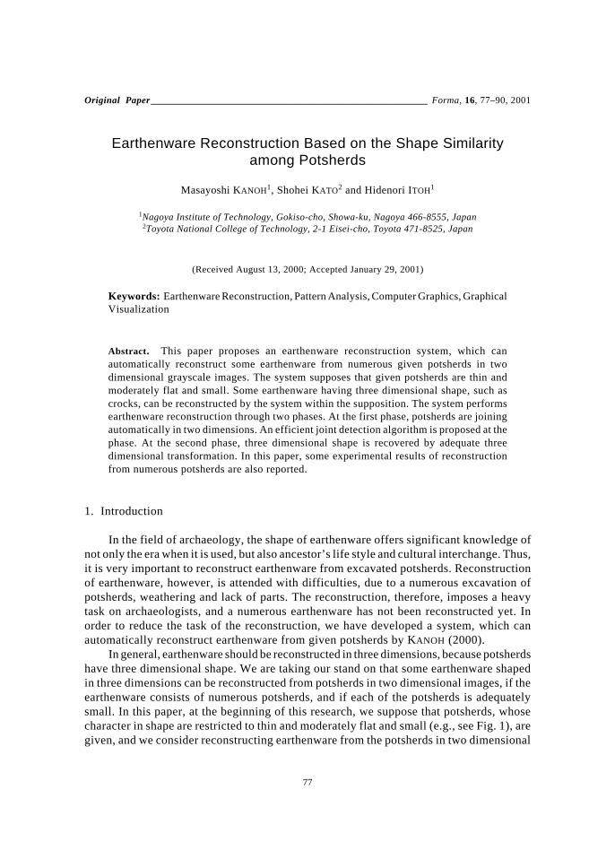
In general, earthenware should be reconstructed in three dimensions, because potsherdshave three dimensional shape. We are taking our stand on that some earthenware shapedin three dimensions can be reconstructed from potsherds in two dimensional images, if theearthenware consists of numerous potsherds, and if each of the potsherds is adequatelysmall. In this paper, at the beginning of this research, we suppose that potsherds, whosecharacter in shape are restricted to thin and moderately flat and small (e.g., see Fig. 1), aregiven, and we consider reconstructing earthenware from the potsherds in two dimensional
78 M. KANOH et al.
grayscale. In this paper, firstly as techniques for reconstruction in two dimensions, wepropose a method for detection of salient feature and calculation of salient value fromcontours of potsherds, and then propose an efficient joint detection algorithm consideringcomplexity of contours. We then move on to a method for recovering three dimensionalshape. We have implemented an earthenware reconstruction system with the proposedalgorithm and method, and shown good performance in reconstruction of a cylindrical clayfigurine (called ento-haniwa in Japanese), in addition to flat objects, such as plates, pot-lids, flat parts of earthenware, and so on.
2. System Overview
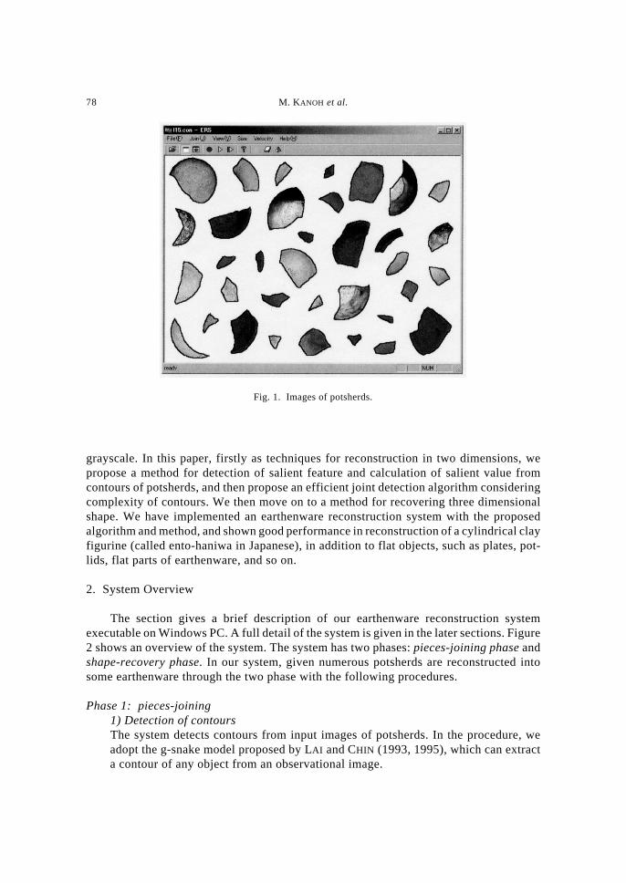
The section gives a brief description of our earthenware reconstruction systemexecutable on Windows PC. A full detail of the system is given in the later sections. Figure2 shows an overview of the system. The system has two phases: pieces-joining phase andshape-recovery phase. In our system, given numerous potsherds are reconstructed intosome earthenware through the two phase with the following procedures.
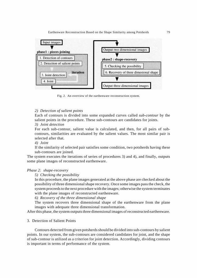
Phase 1: pieces-joining1) Detection of contoursThe system detects contours from input images of potsherds. In the procedure, weadopt the g-snake model proposed by LAI and CHIN (1993, 1995), which can extracta contour of any object from an observational image.
Fig. 1. Images of potsherds.
Earthenware Reconstruction Based on the Shape Similarity among Potsherds 79
2) Detection of salient pointsEach of contours is divided into some expanded curves called sub-contour by thesalient points in the procedure. These sub-contours are candidates for joints.3) Joint detectionFor each sub-contour, salient value is calculated, and then, for all pairs of sub-contours, similarities are evaluated by the salient values. The most similar pair isselected after that.4) JointIf the similarity of selected pair satisfies some condition, two potsherds having thesesub-contours are joined.
The system executes the iterations of series of procedures 3) and 4), and finally, outputssome plane images of reconstructed earthenware.
Phase 2: shape-recovery5) Checking the possibilityIn this procedure, the plane images generated at the above phase are checked about thepossibility of three dimensional shape recovery. Once some images pass the check, thesystem proceeds to the next procedure with the images; otherwise the system terminateswith the plane images of reconstructed earthenware.6) Recovery of the three dimensional shapeThe system recovers three dimensional shape of the earthenware from the planeimages with adequate three dimensional transformation.
After this phase, the system outputs three dimensional images of reconstructed earthenware.
3. Detection of Salient Points
Contours detected from given potsherds should be divided into sub-contours by salientpoints. In our system, the sub-contours are considered candidates for joint, and the shapeof sub-contour is utilized as a criterion for joint detection. Accordingly, dividing contoursis important in terms of performance of the system.
Fig. 2. An overview of the earthenware reconstruction system.
80 M. KANOH et al.
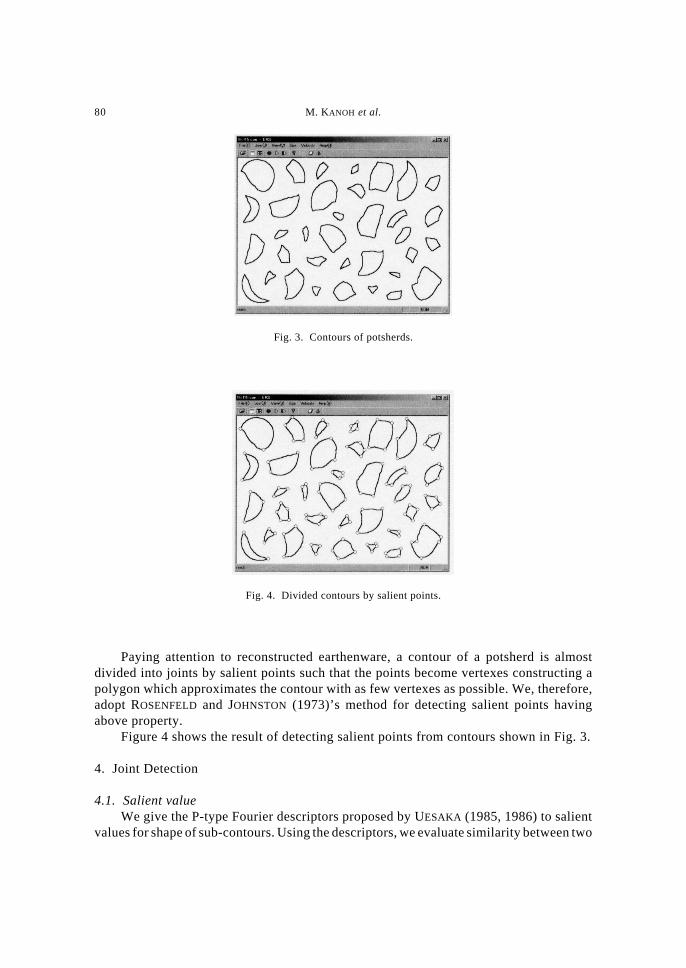
Paying attention to reconstructed earthenware, a contour of a potsherd is almostdivided into joints by salient points such that the points become vertexes constructing apolygon which approximates the contour with as few vertexes as possible. We, therefore,adopt ROSENFELD and JOHNSTON (1973)’s method for detecting salient points havingabove property.
Figure 4 shows the result of detecting salient points from contours shown in Fig. 3.
4. Joint Detection
4.1. Salient valueWe give the P-type Fourier descriptors proposed by UESAKA (1985, 1986) to salient
values for shape of sub-contours. Using the descriptors, we evaluate similarity between two
Fig. 3. Contours of potsherds.
Fig. 4. Divided contours by salient points.
Earthenware Reconstruction Based on the Shape Similarity among Potsherds 81
sub-contours. The descriptors are represented by the Fourier transform of curves andcharacterized as follows:
• It is applicable to expanded curves.• Two endpoints of a reproduced curve always correspond to two endpoints of the
original one, respectively.• Information about a certain shape of an original curve is concentrated in low frequency
range.• A Curve is represented by only the angular function.
In earthenware reconstruction, the shape of a sub-contour is not completely equal tothe shape of its joining pair because of weathering and so on. The P-type Fourier descriptorsare, therefore, applicable to joint detection. A salient value cN(k) of a sub-contour c iscalculated by low-pass spectrum with cut frequency N of Fourier transformation asfollows:
c kn
i j ik n k N NNi
n
( ) = ( ) −( ) = −( ) ( )=
−
∑12 1
0
1
ω πexp / , ..., ,
where ω(i) is the P-type expression of c and n is an enough large natural number. For moreprecise, please refer to UESAKA (1985, 1986).
Using the salient value, similarity εa,b(φ) between sub-contour a and b can beevaluated by the following equation:
ε φ φ φ πa b N Nk N
N
a k j b k, exp , ..., ,( ) = ( ) − ( ) ( ) =( ) ( )=−∑ 2
0 2 2
where aN(k) and bN(k) denote the low-pass spectrums of P-type Fourier descriptors of a andb, respectively.
4.2. Shape similarityThe P-type Fourier descriptors are invariant under translations, and changes of the
scale. Rotations of an original curve are represented by the descriptors multiplied byexp(jφ). It follows from Eq. (2) that b becomes more similar to a when εa,b(φ) gets nearerto zero. It also follows that εa,b(φ) = 0 when the shape of b is completely equivalent to theshape of a.
In our system, we, therefore, define the shape similarity between a and b by thefollowing equation:
ss a ba b
,min
.,
( ) = ( ) ( )13
φ ε φ
The above salient value and similarity are also adopted by the existent work in HORI
(1999).
82 M. KANOH et al.
4.3. JDIDIn our system, an efficient joint detection algorithm considering complexity of
contours, JDID proposed by KANOH (2000), is implemented. The algorithm reducescomputational cost of joint detection drastically, therefore numerous potsherds can bereconstructed at once. For a contour, the algorithm considers some contours approximatingit by different precision, shape-precision, and suitably selects one approximation forcalculating shape similarity by complexity of the contour.
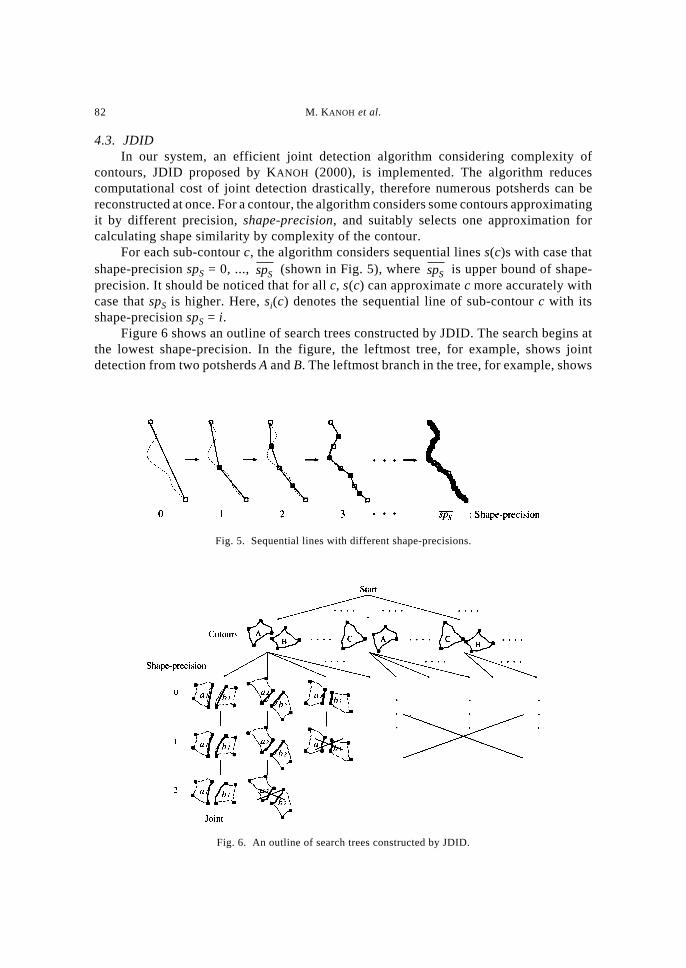
For each sub-contour c, the algorithm considers sequential lines s(c)s with case thatshape-precision spS = 0, ..., spS (shown in Fig. 5), where spS is upper bound of shape-precision. It should be noticed that for all c, s(c) can approximate c more accurately withcase that spS is higher. Here, si(c) denotes the sequential line of sub-contour c with itsshape-precision spS = i.
Figure 6 shows an outline of search trees constructed by JDID. The search begins atthe lowest shape-precision. In the figure, the leftmost tree, for example, shows jointdetection from two potsherds A and B. The leftmost branch in the tree, for example, shows
Fig. 5. Sequential lines with different shape-precisions.
Fig. 6. An outline of search trees constructed by JDID.
Earthenware Reconstruction Based on the Shape Similarity among Potsherds 83
a comparison of shape between two sub-contours a1 and b1 in A and B respectively. In thebranch, a node at the depth of i (i > 0) has two sequential lines si–1(a1) and si–1(b2). A nodeat the deeper depth has sequential lines with their higher shape-precision. The searchproceeds in the breadth-first manner with iterative deepening (KORF, 1985a, b). Nodeexpansion at the depth of i behaves intuitively as follows:
i) calculate shape similarity ss(si–1(a), si–1(b)), and then judge whether the pair is ajoint or not,
ii) from the above judgment, delete nodes containing inconsistent pairs (see nodesmarked with × in Fig. 6),
iii) go on in either of following three ways according to the number of remainingnodes at the same depth:
zero: terminate the search in failure,one: terminate the search in success, and detect the pair of sub-contours in
the node as joint,more than one: generate a descendant node, which contains pair (si(a), si(b)) of sub-
contours, with their shape-precision spS = i.The search iterates the above node expansion in breadth-first manner with successivelyheightening shape-precision.
In the last of this section, let us discuss the of JDID for our earthenware reconstructionsystem. Although there generally exists more than one joint pair in given potsherds, JDIDdetects only one joint pair at once. In other words, our system performs reconstruction ofearthenware by executing JDID successively for each step of joining. At one step, JDIDdose not consider global evaluation (i.e., considering not all combination of sub-contoursfor all steps of joining) for selection of the most similar pair, but considers local evaluation(i.e., considering all combination of sub-contours at the one step). Earthenware reconstructedby our system, thus, cannot always have an optimal combination of joint pairs, while themost similar pair selected by JDID is the best in each step, that is, our system finds quasi-optimal solution. Considering global evaluation for selection causes that earthenwarereconstruction becomes a NP-hard problem, and it is almost impossible to propose anoptimal algorithm which can solve the problem in adequate execution time. JDID,therefore, aims to detect a pair efficiently, which can be adequate joint pair for earthenwarereconstruction. For more precise about JDID algorithm, please refer to KANOH (2000).
5. Three Dimensional Shape Recovery
In this section, we describe a technique for shape-recovery phase in our system:recovery of three dimensional shape from plane images of earthenware reconstructed atpieces-joining phase (see Sec. 2). In general, earthenware having solid shape should bereconstructed from potsherds represented in three dimensions. The technique is an attemptfor our system to reconstruct earthenware, having solid shape, from two dimensionalimages of its potsherds. In our system, it should be noticed that all input potsherds havecharacter restricted in shape: thin and moderately flat and small.
In shape-recovery phase, by two procedures, a plane image of reconstructed earthenwareis transformed into a three dimensional image representing solid shape of the earthenware.The procedures are described briefly in the following sections.
84 M. KANOH et al.
5.1. Checking the possibilityThis procedure checks the plane image about the possibility of three dimensional
shape recovery. The check is whether a contour of the plane image contains any joint pairof sub-contours and the pair is configurationally consistent, or not. The procedure can bedone efficiently by utilizing our proposed JDID algorithm. If some joint pair is found, theplane image is cognizable as a figure to which a solid object is developed.
5.2. Recovery of the three dimensional shapeIn this procedure, the system recovers three dimensional shape of the earthenware
from the development figure with adequate three dimensional transformation. By thetransformation, a development figure behaves intuitively as follows. Firstly, the pairs in thefigure detected by the above procedure are joined, and the figure has one closed-spaceconstructed in three dimensions. And then, the figure is gradually modified so that thevolume of its closed-space becomes the largest.
In case that the figure is to grow into cylinder shape or cone shape (such like a papercup), the transformation can achieve drastic efficiency by means of some geometricalcharacteristics. The specialized transformation is shown in Appendix.
6. Experimental Results
We have implemented earthenware reconstruction system in C++ on a PentiumIII 500MHz running Windows PC. We have also made some experiments of earthenwarereconstruction from excavated potsherds. This section shows two representative experimentsverifying effectiveness of our system; one is for efficiency in pieces-joining phase, andanother is for performance of shape-recovery phase. In the experiments, parameters for oursystem, N = 5 and n = 64 × 2i, where i is a value of shape-precision.
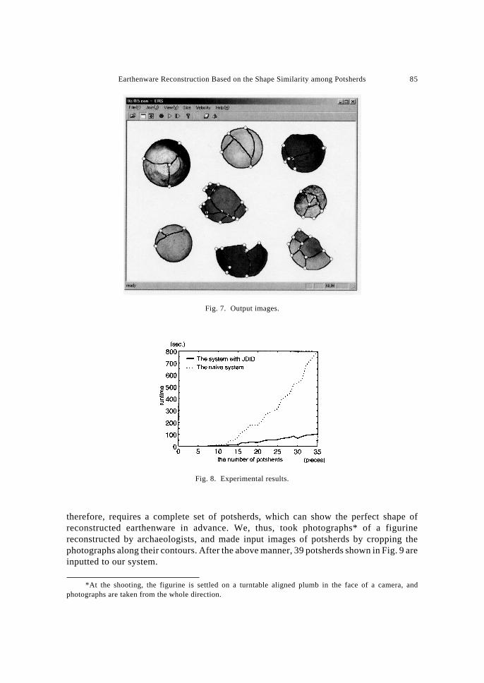
6.1. Efficiency in pieces joiningIn order to verify efficiency of pieces-joining phase, we have given 35 potsherds
shown in Fig. 1 to our system. Figure 7 shows earthenware reconstructed by our system.In this particular example, the result indicates that our system can correctly and completelyreconstruct 8 pieces of earthenware from given potsherds.
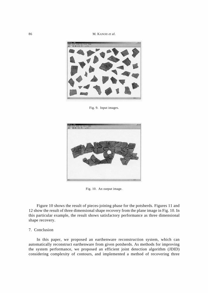
We have, moreover for effectiveness of JDID, compared execution time of our systemwith a naive system, by changing the number of potsherds. In the naive system, jointdetection is executed with shape-precision fixed on the upper bound. Figure 8 shows theexperimental results. The solid line in the figure shows the runtime by our system, whilethe broken line is those by the naive system. The results indicates that our system embeddedwith JDID becomes faster than the naive system as the number of potsherds increases. Oursystem, for example of 35 potsherds shown in Fig. 1, takes 104.9 (sec.) to perform allreconstruction, and the execution time is about 7.6 times faster than naive system.
6.2. Performance of three dimensional shape recoveryWe have also made an experiment for recovery of three dimensional shape of
cylindrical clay figurines. Our aim of this experiment is to ascertain that our system cancorrectly recover the three dimensional shape from given potsherds. This experiment,
Earthenware Reconstruction Based on the Shape Similarity among Potsherds 85
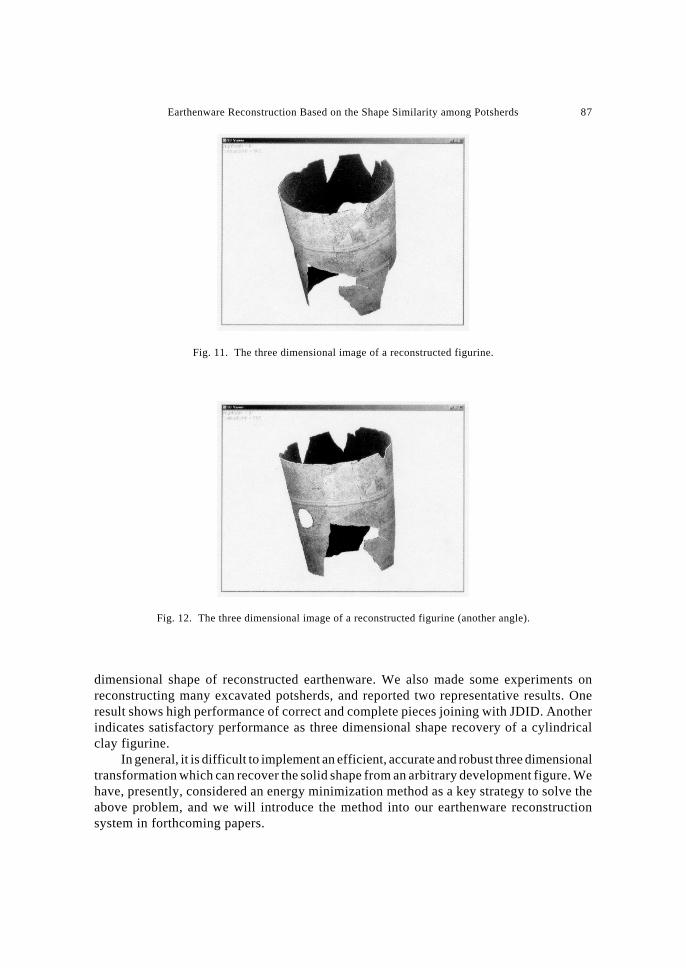
therefore, requires a complete set of potsherds, which can show the perfect shape ofreconstructed earthenware in advance. We, thus, took photographs* of a figurinereconstructed by archaeologists, and made input images of potsherds by cropping thephotographs along their contours. After the above manner, 39 potsherds shown in Fig. 9 areinputted to our system.
Fig. 7. Output images.
Fig. 8. Experimental results.
*At the shooting, the figurine is settled on a turntable aligned plumb in the face of a camera, andphotographs are taken from the whole direction.
86 M. KANOH et al.
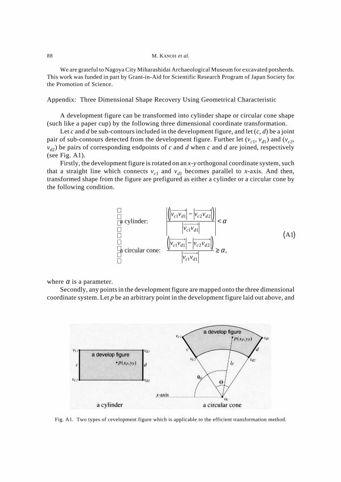
Figure 10 shows the result of pieces-joining phase for the potsherds. Figures 11 and12 show the result of three dimensional shape recovery from the plane image in Fig. 10. Inthis particular example, the result shows satisfactory performance as three dimensionalshape recovery.
7. Conclusion
In this paper, we proposed an earthenware reconstruction system, which canautomatically reconstruct earthenware from given potsherds. As methods for improvingthe system performance, we proposed an efficient joint detection algorithm (JDID)considering complexity of contours, and implemented a method of recovering three
Fig. 9. Input images.
Fig. 10. An output image.
Earthenware Reconstruction Based on the Shape Similarity among Potsherds 87
Fig. 11. The three dimensional image of a reconstructed figurine.
Fig. 12. The three dimensional image of a reconstructed figurine (another angle).
dimensional shape of reconstructed earthenware. We also made some experiments onreconstructing many excavated potsherds, and reported two representative results. Oneresult shows high performance of correct and complete pieces joining with JDID. Anotherindicates satisfactory performance as three dimensional shape recovery of a cylindricalclay figurine.
In general, it is difficult to implement an efficient, accurate and robust three dimensionaltransformation which can recover the solid shape from an arbitrary development figure. Wehave, presently, considered an energy minimization method as a key strategy to solve theabove problem, and we will introduce the method into our earthenware reconstructionsystem in forthcoming papers.
88 M. KANOH et al.
We are grateful to Nagoya City Miharashidai Archaeological Museum for excavated potsherds.This work was funded in part by Grant-in-Aid for Scientific Research Program of Japan Society forthe Promotion of Science.
Appendix: Three Dimensional Shape Recovery Using Geometrical Characteristic
A development figure can be transformed into cylinder shape or circular cone shape(such like a paper cup) by the following three dimensional coordinate transformation.
Let c and d be sub-contours included in the development figure, and let (c, d) be a jointpair of sub-contours detected from the development figure. Further let (vc1, vd1) and (vc2,vd2) be pairs of corresponding endpoints of c and d when c and d are joined, respectively(see Fig. A1).
Firstly, the development figure is rotated on an x-y orthogonal coordinate system, suchthat a straight line which connects vc1 and vd1 becomes parallel to x-axis. And then,transformed shape from the figure are prefigured as either a cylinder or a circular cone bythe following condition.
a cylinder:
a circular cone:
A1
v v v v
v v
v v v v
v v
c d c d
c d
c d c d
c d
1 1 2 2
1 1
1 1 2 2
1 1
−( )<
−( )≥
( )
α
α ,
where α is a parameter.Secondly, any points in the development figure are mapped onto the three dimensional
coordinate system. Let p be an arbitrary point in the development figure laid out above, and
Fig. A1. Two types of cevelopment figure which is applicable to the efficient transformation method.
Earthenware Reconstruction Based on the Shape Similarity among Potsherds 89
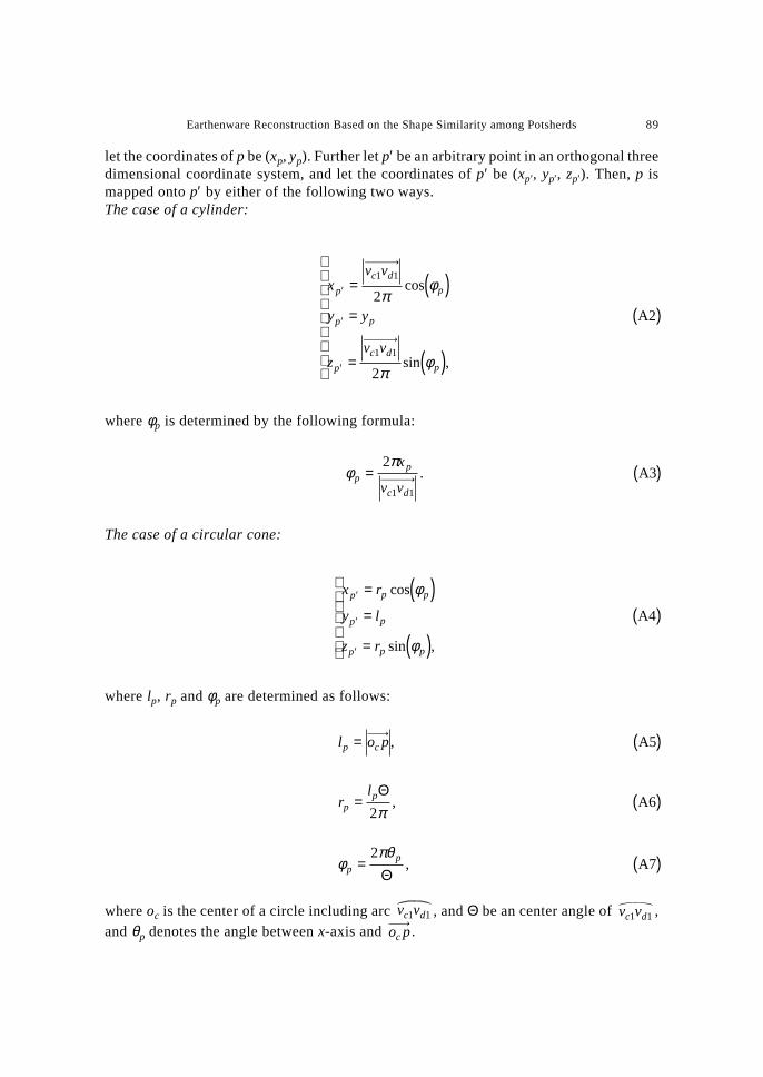
let the coordinates of p be (xp, yp). Further let p′ be an arbitrary point in an orthogonal threedimensional coordinate system, and let the coordinates of p′ be (xp′, yp′, zp′). Then, p ismapped onto p′ by either of the following two ways.The case of a cylinder:
xv v
y y
zv v
p
c d
p
p p
p
c d
p
′
′
′
= ( )=
= ( )
( )
1 1
1 1
2
2
πφ
πφ
cos
sin ,
A2
where φp is determined by the following formula:
φπ
pp
c d
x
v v= ( )
2
1 1
. A3
The case of a circular cone:
x r
y l
z r
p p p
p p
p p p
′
′
′
= ( )=
= ( )
( )cos
sin ,
φ
φ
A4
where lp, rp and φp are determined as follows:
l o pp c= ( ), A5
rl
pp= ( )Θ
2π, A6
φπθ
pp= ( )
2
Θ, A7
where oc is the center of a circle including arc v vc d1 1 , and Θ be an center angle of v vc d1 1 ,and θp denotes the angle between x-axis and o pc .
90 M. KANOH et al.
REFERENCES
HORI, K., IMAI, M. and OGASAWARA, T. (1999) Joint detection for potsherds of broken earthenware, Proceedingsof Computer Vision and Pattern Recognition ’99, 2, 440–445.
KANOH, M., KATO, S. and ITOH, H. (2000) Efficient joint detection considering complexity of contours, The 6thPacific Rim International Conference on Artificial Intelligence (PRICAI 2000), pp. 588–598.
KORF, R. E. (1985a) Depth-first iterative-deepening: An optimal admissible tree search, Artif. Intell., 27, 97–109.
KORF, R. E. (1985b) Iterative-deepening-A*: An optimal admissible tree search, in Proc. of the 9th IJCAI, pp.1034–1036.
LAI, K. F. and CHIN, L. (1993) On regularization, formulation, and initialization of the active contour models(snakes), Asian Conference on Computer Vision, pp. 542–545.
LAI, K. F. and CHIN, L. (1995) Deformable contours: Modeling and extraction, IEEE Trans. Pattern Analysisand Machine Intelligence, 17, No. 11, 1084–1090.
ROSENFELD, A. and JOHNSTON, E. (1973) Angle detection on digital curves, IEEE Transactions on Computers,22, 875–878.
UESAKA, Y. (1985) Spectral analysis and complexity of form, Proceedings of the 8th Symposium on AppliedFunctional Analysis, pp. 18–29.
UESAKA, Y. (1986) Spectral analysis of form based on Fourier descriptors, Science on Form, Proceedings of the1st International Symposium for Science on Form, pp. 405–412.