deformed shape and stress reconstruction in plate and ...deformed shape and stress reconstruction in...
TRANSCRIPT
National Aeronautics and Space
Administration
www.nasa.gov
Deformed Shape and Stress Reconstruction in Plate and Shell Structures Undergoing Large Displacements: Application of Inverse Finite Element Method using Fiber-Bragg-Grating Strains
A. Tessler, J. Spangler, M.Gherlone, M. Mattone, and M. Di Sciuva NASA Langley Research Center, U.S.A. & Politecnico di Torino, Italy
WCCM 2012 Sao Paulo, Brazil (8-13 July 2012)
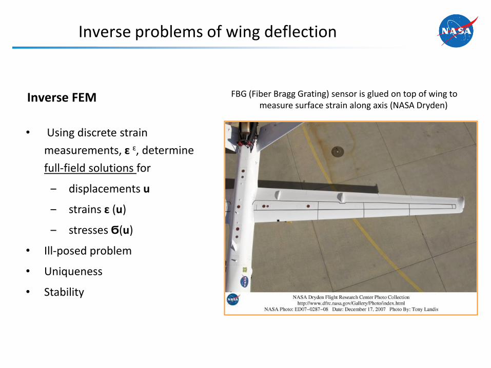
Inverse problems of wing deflection
FBG (Fiber Bragg Grating) sensor is glued on top of wing to measure surface strain along axis (NASA Dryden)
• Using discrete strain
measurements, ɛ ɛ, determine
full-field solutions for
‒ displacements u
‒ strains ɛ (u)
‒ stresses Ϭ(u)
• Ill-posed problem
• Uniqueness
• Stability
Inverse FEM

Variational Formulation based on First-Order Shear Deformation Theory (Mindlin)

Kinematic Assumptions of First-Order Shear Deformation Theory
• Deformations
– Membrane
– Bending
– Transverse shear
( , ) ( ) ( )
( , ) ( ) ( )
( ) ( )
x y
y x
z
u z u z
u z v z
u w
x x x
x x x
x x
( , ) (strain-measurement directions)
[ , ] (thickness coordinate)
x y
z t t
x
2t
z, w
y, v y
x
x, u
4
Strain rosettes or FBG fiber along x direction
• Displacement components
Top-surface measured strains
Bottom-surface measured strains
xx
yy
xy
xx
yy
xy
2t
z
Reference frame (aligned with strain-measurement directions)

Strains and Section Strains
1 4
2 5
3 6
xx
yy
xy
z
5
• Section strains
1
2
3
0 0 0 0
0 0 0 0
0 0 0
x
m
y
xy x
y
u
v
w
e u L u
4
5
6
0 0 0 0
0 0 0 0
0 0 0
x
b
y
xx y
y
u
v
w
k u L u
3 membrane section strains
3 bending section strains
7
8
0 0 0 1
0 0 1 0
x s
y
x
y
u
v
w
g u L u
• Inplane strains (=6) • Transverse-shear strains (=2)

Strain measurements relate to membrane & bending section strains
4
5
6
1
2
xx xx
i yy yy
xy xy
t
k
1
2
3
1
2
xx xx
i yy yy
xy xy
e
top rosette
bottom rosette
xx
yy
xy
xx
yy
xy
2t
z
1 4
2 5
3 6
xx
yy
xy
z
Express measured strains in terms of FSDT
Evaluating at top and bottom ( )
Surface strains measured at location
z t
6
x
7
8
Cannot be obtained from surface strains
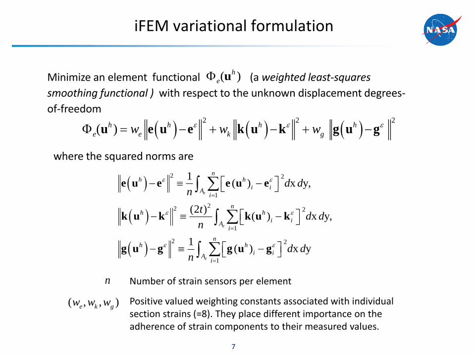
iFEM variational formulation
Minimize an element functional (a weighted least-squares
smoothing functional ) with respect to the unknown displacement degrees-
of-freedom
7
2 2 2
( )h h h h
e e k gw w w u e u e k u k g u g
where the squared norms are
2 2
1
22 2
1
2 2
1
1( ) x y,
(2 )( ) x y,
1( ) x y
e
e
e
nh h
i iA
i
nh h
i iA
i
nh h
i iA
i
d dn
td d
n
d dn
e u e e u e
k u k k u k
g u g g u g
Positive valued weighting constants associated with individual section strains (=8). They place different importance on the adherence of strain components to their measured values.
( , , )e k gw w w
n Number of strain sensors per element
( )h
e u
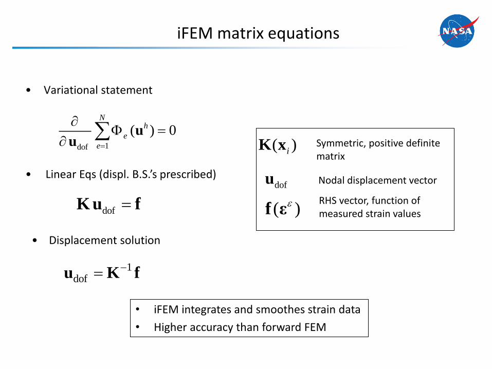
• Variational statement
iFEM matrix equations
Symmetric, positive definite matrix
dofu
( )iK x
Nodal displacement vector
( )f εRHS vector, function of measured strain values
1dof
( ) 0N
h
e
e
u
u
dof K u f
• Linear Eqs (displ. B.S.’s prescribed)
• iFEM integrates and smoothes strain data
• Higher accuracy than forward FEM
1dof
u K f
• Displacement solution

iFEM’s selective, element-level (local) regularization
1. An element is missing measured transverse-shear section strains
(standard case); Let
9
2
2( ) x y ( ; 1)e
h h
g e kA
d d w w w g u g u
2. An element is missing all measured section strains (in addition to (1))
22
22 2
( ) x y ( )
(2 ) ( ) x y ( )
e
e
h h
eA
h h
kA
d d w
t d d w
e u e u
k u k u
3. An element is missing some measured-strain components
‒ apply forms (2) to the missing components only
Important special cases
410 (small positive constant)
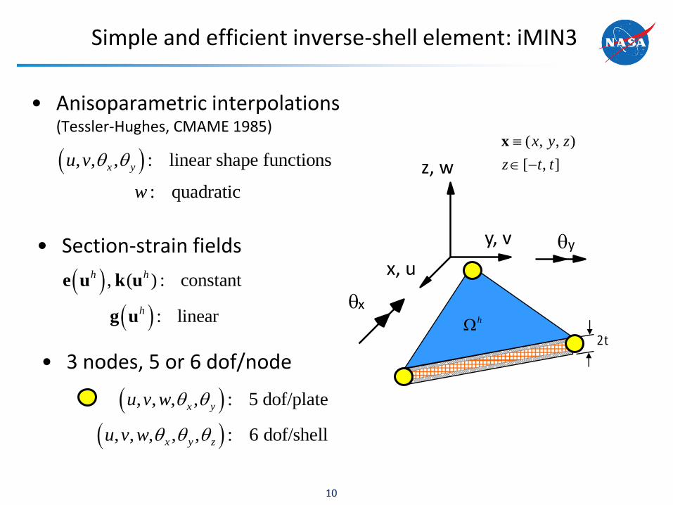
Simple and efficient inverse-shell element: iMIN3
• Anisoparametric interpolations (Tessler-Hughes, CMAME 1985)
, , , : linear shape functions
: quadratic
x yu v
w
10
, ( ) : constant
: linear
h h
h
e u k u
g u
• Section-strain fields
• 3 nodes, 5 or 6 dof/node
( , , )
[ , ]
x y z
z t t
x
2t
z, w
y, v y
x
x, u
h
, , , , : 5 dof/plate
, , , , , : 6 dof/shell
x y
x y z
u v w
u v w
Demonstration problem
11

FEM shell model: Aluminum stiffened flap with two rectangular cut-outs
12
F = (1, 50)
Un-Deformed
Deformed
Elastostatic deformations (ABAQUS/STRI3 (Batoz) 3-node element, no shear deformation; 6 section strains only)
causes geometrically nonlinear response
12 in
• Model has 10 planar element groups
• Each group has its own material reference frame to define strain orientations

3 iFEM modeling and stabilization schemes
13
Model A: Six FEM section strains are mapped onto all iFEM elements • One-to-one (high-fidelity) • All elements have strain data but no
shear strain measurements
Model B: Six FEM section strains are mapped onto perimeter iFEM elements • Simulates tri-axial strain rosettes
along the perimeter • Interior elements have no strain
data including the stiffener (local regularization)
Model C: Two FEM section strains (axial) are mapped onto perimeter iFEM elements • Simulates linear strain gauges or
FBG strain sensors • Incomplete strain data • Interior elements have no strain
data including the stiffener (local regularization)
Axial strain measurements only in perimeter elements
Tri-axial strain measurements in perimeter (red) elements
Tri-axial strain measurements in every element

Linear problem: % error in reconstructed displacement, uz
14
Model A: Six FEM section strains are mapped onto all iFEM elements
Model B: Six FEM section strains are mapped only onto perimeter iFEM elements
Model C: Two FEM section strains (axial) are mapped only onto perimeter iFEM elements
Ref i Est i
Max
Ref
u u% Error (u ) =
u100z
zz
z
0.45%
0.70%
1.1%

Linear problem: Deviations in uz
15
iFEM 0% noise 5% noise model in strains in strains A 1.00000 0.99998 B 0.99999 0.99998 C 0.99998 0.99985
Pearson correlation, r
iFEM 0% noise 5% noise model in strains in strains A 0.00017 0.00096 B 0.00020 0.00074 C 0.00035 0.00098
RMS
iFEM 0% noise 5% noise model in strains in strains A 0.1951 1.0505 B 0.1934 0.8353 C 0.3575 1.0769
Mean % error

Linear problem: % error in reconstructed von Mises stress (bottom shell surface)
16
Model A: Six FEM section strains are mapped onto all iFEM elements
Model B: Six FEM section strains are mapped only onto perimeter iFEM elements
Model C: Two FEM section strains (axial) are mapped only onto perimeter iFEM elements
Ref i Est i
Max
Ref
% Error ( ) = 100

Linear problem: Deviations in von Mises stress
17
iFEM 0% noise 5% noise model in strains in strains A 0.9994 0.9993 B 0.9842 0.9844 C 0.9903 0.9896
Pearson correlation, r
iFEM 0% noise 5% noise model in strains in strains A 4.0149 5.72724 B 21.9314 23.4736 C 15.7996 16.9735
RMS
N
Ref i Ref EST i Esti 1
N N2 2
Ref i Ref Est i Esti 1 i 1
( )r
( )
2
REF i EST i1σ σ
N
iRMSN
Ref i Est i
M x
ef1 a
R
σ σ
σ
1100
N
iN
• Mean % error
• Pearson correlation, r
• Root-Mean-Square error
iFEM 0% noise 5% noise model in strains in strains A 0.3786 0.5553 B 1.6796 1.8404 C 1.3501 1.5133
Mean % error
iFEM incremental algorithm for nonlinear deformations
• Use Nonlinear FEM as a virtual experiment (Lagrangean reference
frame)
– At each load increment of NL-FEM, compute the incremental section
strains (6 components) that represent measured strain increments
– Perform iFEM analysis using the strain increments to obtain the
displacements and rotations
– Update the geometry of iFEM mesh due to deformation using iFEM
determined displacements, i.e., x1=x0+u1
– Perform iFEM using the strain increments of the next load increment, and
update the geometry for the next step x2=x1+u2
18
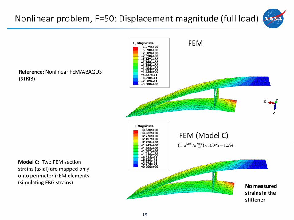
Nonlinear problem, F=50: Displacement magnitude (full load)
19
Model C: Two FEM section strains (axial) are mapped only onto perimeter iFEM elements (simulating FBG strains)
Reference: Nonlinear FEM/ABAQUS (STRI3)
Max Max
Ref(1-u /u ) 100% 1.2%
FEM
iFEM (Model C)
No measured strains in the stiffener

Nonlinear problem: Displacement magnitude (full load) of the stiffener
20
Model C: Two FEM section strains (axial) are mapped only onto perimeter iFEM elements (simulating FBG strains)
Reference: Nonlinear FEM/ABAQUS (STRI3)
Max Max
Ref(1-u /u ) 100% 1.5%
FEM
iFEM (Model C)
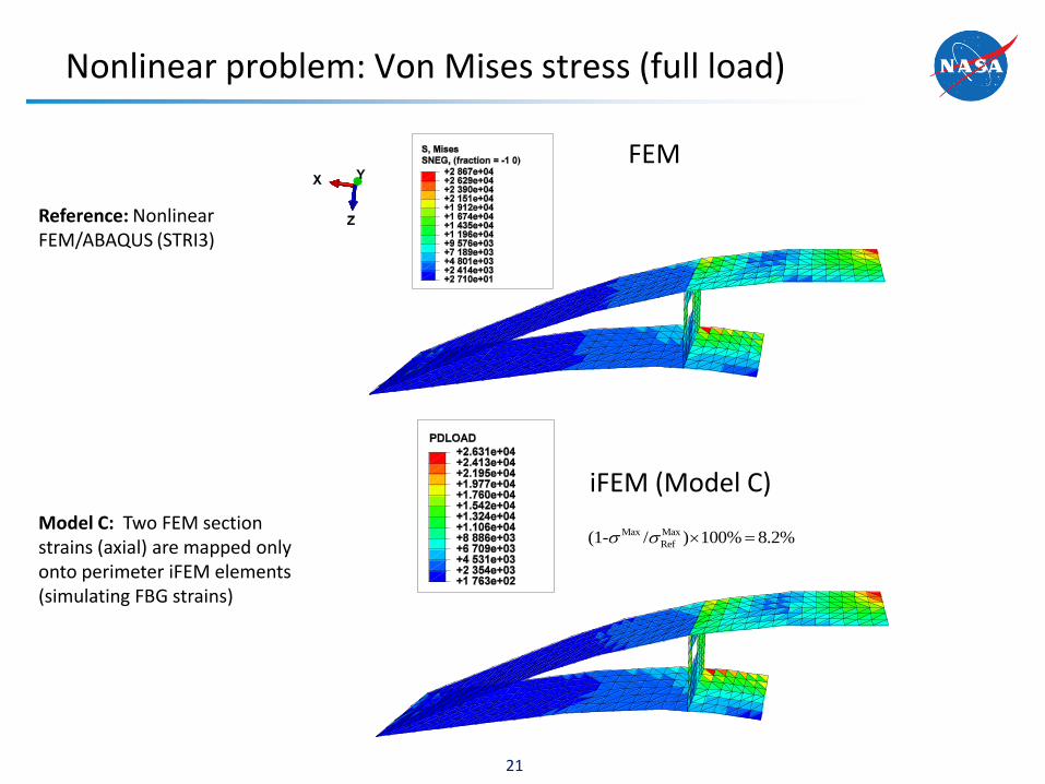
Nonlinear problem: Von Mises stress (full load)
21
Model C: Two FEM section strains (axial) are mapped only onto perimeter iFEM elements (simulating FBG strains)
Reference: Nonlinear FEM/ABAQUS (STRI3)
FEM
iFEM (Model C)
Max Max
Ref(1- / ) 100% 8.2%

Summary
• On-board SHM of nextgen aircraft, spacecraft, large space
structures, and habitation structures
– Safe, reliable, and affordable technologies
• Inverse FEM algorithms for FBG strain measurements
– Real-time efficiency, robustness, superior accuracy
– Stable full-field solutions
• Inverse FEM theory
– Strain-displacement relations & integrability conditions
fulfilled
– Independent of material properties
– Solutions stable under small changes in input data
– Linear and nonlinear response
22

Summary (cont’d)
• Inverse FEM’s architecture/modeling
– Architecture as in standard FEM (user routine in ABAQUS)
– Superior accuracy on coarse meshes
– Frames, plates/shell and built-up structures
– Thin and moderately thick regime
– Low and higher-order elements
• Inverse FEM applications
– Computational studies: plate and built-up shell structures
– Experimental studies with plates: FBG strains and strain
rosettes
23
Summary (cont’d)
• Inverse FEM’s architecture/modeling
– Architecture as in standard FEM (user routine in ABAQUS)
– Superior accuracy on coarse meshes
– Frames, plates/shell and built-up structures
– Thin and moderately thick regime
– Low and higher-order elements
• Inverse FEM applications
– Computational studies: plate and built-up shell structures
– Experimental studies with plates: FBG strains and strain
rosettes
24