e6c3 rotary encoder (incremental/absolute) datasheetomron\pdf\encoders\e6c3.pdf · rotary encoder...
TRANSCRIPT

Rotary Encoder (Incremental/Absolute) E6C3 1
Rotary Encoder (Incremental/Absolute)
E6C3An Encoder That Offers Durability and Convenience
• IP65f drip-proof, oil-proof construction with sealed bearing.• 8-mm-dia stainless steel shaft withstands a shaft loading of
80 N and 50 N respectively in the radial and thrust direc-tions.
• Absolute Rotary Encoders have a metal slit plate to ensure high resistance to shock.
• Combining Absolute Rotary Encoders with a Programma-ble Controller or Cam Positioner allows ideal angle control.
• CE markings (EMC Directives) and conforms to EN/IEC standards.
Ordering Information
Incremental Rotary EncodersStock Note: Shaded items are normally stocked.
Note: 1. When ordering, specify the resolution in addition to the model numbers. (Example: E6C3-CWZ5GH 300P/R 1M)2. Models with 2-m cables are also available as standard products. Specify the cable length at the end of the model number. (Example:
E6C3-CWZ5GH 300P/R 2M)
Supply voltage Output configuration Resolution (P/R) Connection method Model
12 to 24 VDC Complementary output 100, 200 Pre-wired (1 m) (See note 2.) E6C3-CWZ5GH
300 360, 500
600, 720, 800
1,000 1,024, 1,200
1,500, 1,800, 2,000
2,048, 2,500, 3,600
5 to 12 VDC Voltage output 100, 200 E6C3-CWZ3EH
300, 360, 500
600, 720, 800
1,000, 1,024, 1,200
1,500, 1,800, 2,000
2,048, 2,500, 3,600
5 to 12 VDC Line driver output 100, 200 E6C3-CWZ3XH
300, 360, 500
600, 720, 800
1,000, 1,024, 1,200
1,500, 1,800, 2,000
2,048, 2,500, 3,600

2 Rotary Encoder (Incremental/Absolute) E6C3
Absolute Rotary EncodersStock Note: Shaded items are normally stocked.
Note: 1. When ordering, specify the resolution in addition to the model numbers. (Example: E6C3-AG5C 360P/R 1M)2. Models with 2-m cables are also available as standard products. Specify the cable length at the end of the model number. (Example: E6C3-
AG5C 360P/R 2M)3. When connecting to the H8PS, be sure to use the E6C3-AG5C-C 256P/R.
Accessories (Order Separately)Stock Note: Shaded items are normally stocked.
Supply voltage Output configuration Output code Resolution (P/R) Connection method Model
12 to 24 VDC NPN open collector output Gray code 256, 360 Connector E6C3-AG5C-C (See note 3)
256, 360, 720, 1,024 Pre-wired (1 m) (See note 2.)
E6C3-AG5C
Binary 32, 40 E6C3-AN5C
BCD 6, 8, 12 E6C3-AB5C
PNP open collector output Gray code 256, 360, 720, 1,024 E6C3-AG5B
Binary 32, 40 E6C3-AN5B
BCD 6, 8, 12 E6C3-AB5B
5 VDC Voltage output Binary 256 E6C3-AN1E
12 VDC E6C3-AN2E
Item Remarks Model
Coupling --- E69-C08B
Diameters of ends: 6 to 8 dia. E69-C68B
Flange --- E69-FCA03
E69-2 Servo Mounting Bracket provided. E69-FCA04
Servo Mounting Bracket Provided with the E69-FCA04 Flange. E69-2
Extension Cable 5 m Applicable for the E6C3-AG5C-C. 15- and 98-m-long Extension Cables are also available.
E69-DF5
10 m E69-DF10
30 m E69-DF20

Rotary Encoder (Incremental/Absolute) E6C3 3
Specifications
Ratings/Characteristics
Incremental Rotary Encoders
Note: 1. An inrush current of approx. 9 A flows for approx. 0.1 ms right after the E6C3 is turned on.2. The line driver output of the E6C3 is used for data transmission circuitry conforming to RS-422A and ensures long-distance transmission
over twisted-pair cable, the quality of which is equivalent to AM26LS31.3. The maximum electrical response revolution is determined by the resolution and maximum response frequency as follows:
Maximum electrical response frequency (rpm) = Maximum response frequency/resolution × 60This means that the E6C3 will not operate electrically if its revolution exceeds the maximum electrical response revolution.
4. JEM1030: applicable since 1991.
Item E6C3-CWZ5GH E6C3-CWZ3EH E6C3-CWZ3XH
Power supply voltage 12 VDC −10% to 24 VDC +15% 5 VDC −5% to 12 VDC +10%
Current consumption(See note 1.)
100 mA max.
Resolution (pulse/rotation)
100, 200, 300, 360, 500, 600, 720, 800, 1,000, 1,024, 1,200, 1,500, 1,800, 2,000, 2,048, 2,500, 3,600
Output phases A, B, and Z A, A, B, B, Z, Z
Output configuration Complementary output (See note 5.) Voltage output (NPN output) Line driver output (See note 2.)
Output capacity Output voltage:VH: Vcc − 3 V min. (Io: 30 mA)VL: 2 V max. (Io: −30 mA)
Output current: ±30 mA
Output resistance: 2 kΩ
Output current: 35 mA max.
Residual voltage: 0.7 V max.
AM26LS31 equivalentOutput current:
High level (Io): −10 mALow level (Is): 10 mA
Output voltage:Vo: 2.5 V min.Vs: 0.5 V max.
Max. response frequency (See note 3.)
125 kHz (65 kHz for phase-Z reset)
Phase difference on output
90°±45° between A and B (1/4T±1/8T)
Rise and fall times of output
1 µs max.(cable length: 2 m, output current: 30 mA)
1 µs max.(cable length: 2 m, output current: 35 mA)
1 µs max. (cable length: 2 m; Io: −10 mA; Is: 10 mA)
Starting torque 10 mN·m max. at room temperature; 30 mN·m max. at low temperature
Moment of inertia 2.0 × 10⁻⁶ kg·m2; 1.9 × 10⁻⁶ kg·m2 at 500 P/R max.
Shaft loading
Radial 80 N
Thrust 50 N
Max. permissible revolution
5,000 rpm
Protection circuits Reversed power supply connection protection circuit, output load short-circuit protection circuit
---
Ambient temperature Operating: −10°C to 70°C (with no icing)Storage: −25°C to 85°C (with no icing)
Ambient humidity 35% to 85% (with no condensation)
Insulation resistance 20 MΩ min. (at 500 VDC) between current-carrying parts and case
Dielectric strength 500 VAC, 50/60 Hz for 1 min between current-carrying parts and case
Vibration resistance 10 to 500 Hz, 150 m/s2 or 2-mm double amplitude for 11 min 3 times each in X, Y, and Z directions
Shock resistance 1,000 m/s2 3 times each in X, Y, and Z directions
Degree of protection IEC60529 IP65 (JEM IP65f for drip-proof and oil-proof construction) (See note 4.)
Connection method Pre-wired (standard length: 1 m)
Weight (packed state) Approx. 300 g
Others Instruction manual

4 Rotary Encoder (Incremental/Absolute) E6C3
5. Complementary Output:The complementary output has two output transistors (NPN and PNP) as shown below. These two output transistors alternately turn ONand OFF depending on the "H" or "L" output signal. When using them, pull up to the positive power or pull down to 0 V. The complementaryoutput allows flow-in or flow-out of the output current and thus the rising and falling speeds of signals are fast. This allows a long cabledistance. They can be connected to open-collector input devices (NPN, PNP).
6. Phase-Z signals are output when the relationship between the shaft’s D cut position and the cable’s pullout direction is as shown in thefollowing diagram. (Output position range: ±15°).
PNP transistor
NPN transistorOUT
E6C3-CWZ5GH
0 V
Power supply
Signal
D cut
40 dia.120°
120°

Rotary Encoder (Incremental/Absolute) E6C3 5
Output Circuit Diagram
Incremental Rotary Encoders
Note: 1. The shield is not connected to the internal circuits or casing of the E6C3.2. There is no difference in circuit among phases A, B, and Z.3. Connect the GND terminal to 0 V or the ground when the E6C3 is in normal operation.
Model/output circuit Output modes Connection
E6C3-CWZ5GH
Voltage Output: E6C3-CWZ3EHComplementary Output: E6C3-CWZ5GH
Color Terminal
Brown Power supply (+VCC)
Black Output phase A
E6C3-CWZ3EH White Output phase B
Orange Output phase Z
Blue 0 V (common)
E6C3-CWZ3XH
Line Driver Output: E6C3-CWZ3XHColor Terminal
Brown Power supply (+VCC)
Black Output phase A
White Output phase B
Orange Output phase Z
Black/Red stripes
Output phase A
White/Red stripes
Output phase B
Orange /Red stripes
Output phase Z
Blue 0 V (common)
Note:Receiver:AM26LS32equivalent
30 mAmax.
30 mAmax.
24 Ω
12 VDC −10% to 24 VDC +15%
0 V
GND
Blue
Brown
Shield
7.5 Ω
7.5 Ω
Main circuit
Black, white, orange
Output signal(Black: Phase A; White: Phase B; Orange: Phase Z)
H
L
H
L
H
L
Phase A
Phase B
Phase Z
H
L
H
L
H
L
Phase A
Phase B
Phase Z
1/4±1/8T (90˚±45˚)
T (360˚)CW
1/4±1/8T (90˚±45˚)
T (360˚)CCW
Rotating direction: Clockwise (CW)(As viewed from the face of the shaft)
Rotating direction: Counterclockwise (CCW)(As viewed from the face of the shaft)
Note: Phase A is 1/4±1/8T faster than phase B.
Note: Phase A is 1/4±1/8T slower than phase B.
2 kΩ
7.5 Ω35 mAmax.
5 VDC −5% to 12 VDC +10%
0 V
GND
Blue
Brown
Shield
Main circuit
NPN transistor
Black, white, orange
Output signal(Black: Phase A; White: Phase B; Orange: Phase Z)
0 V
GND
Blue
Brown
Shield
5 VDC −5% to 12 VDC +10%
Main circuit
Black, white, orange
AM26LS31 or equiva-lent
Non-reversed output(Black: Phase A; White: Phase B; Orange: Phase Z)
Black, white, orange (with red stripes) Reversed output
(Black/Red: Phase A; White/Red: Phase B; Orange/Red: Phase Z
H
L
H
L
H
L
H
L
H
L
H
L
Phase A
Phase B
Phase Z
Phase A
Phase B
Phase Z
H
L
H
L
H
L
H
L
H
L
H
L
Phase A
Phase B
Phase Z
Phase A
Phase B
Phase Z
1/4±1/8T (90°±45°) 1/4±1/8T (90°±45°)
T (360°) T (360°)CW CCW
Rotating direction: Clockwise (CW)(As viewed from the face of the shaft)
Rotating direction: Counterclockwise (CCW)(As viewed from the face of the shaft)

6 Rotary Encoder (Incremental/Absolute) E6C3
Connection Examples
Incremental Rotary Encoders
H7ER Digital Tachometer
Applicable Model: E6C3-CWZ3EH (with a resolution of 10, 60, or 600 P/R)
H7BR Digital Counter
Applicable Model: E6C3-CWZ3EH
H7CR-CW Digital Counter
Applicable Model: E6C3-CWZ5GH
C200H-CT@@ High-speed Counter Unit
Applicable Model: E6C3-CWZ5GHTypical Model: C200H-CT001-V1
Note: Apply the following connections if the E6C3’s 3 power suppliesare 5 or 24 V.Phase A and Power Supply: 5 V to A19 and 24 V to B20Phase B and Power Supply: 5 V to A17 and 24 V to B18
Applicable Model: E6C3-CWZ5GHTypical Model: C200H-CT021
Note: Apply the following connections if the power supply to the E6C3is 12 or 24 V.Phase A and Power Supply: 12 V to A8/B8 and 24 V to A9/B9Phase B and Power Supply: 12 V to A12/B12 and 24 V toA13/B13Phase Z and Power Supply: 12 V to A16/B16 and 24 V toA17/B17
H7ER Digital Tachometer
Brown
Black
Blue
5 to 12 VDC
+12 V0 V
Brown
Black
White
ShieldBlue
H7BR Digital Counter
Black
White
Blue
Brown
12 VDC (100 mA)
H7CR-CW
(Encoder at 0 V)
+24 V
+24 VPhase A
Phase B
+12 V
+12 V
+5 V
+5 V
+12 V
Phase A
Phase B
0 V
12-VDC power supply
+12 V0 V
Phase Z
Phase B
Phase Z
Phase B
0 V
Phase A
+12 V
0 V
Phase Z
Phase B
Phase A Phase A
+12 V0 V
(Encoder at 0 V)
Phase A
12-VDC power supply
5 to 24 VDC

Rotary Encoder (Incremental/Absolute) E6C3 7
CQM1-CPU43-EV1 (as Built-in High-speed Counter)• The pulse output of the E6C3 can be directly input into IN04, IN05,
and IN06 of the CPU Unit to use these three points as a built-inhigh-speed counter.
• The single-phase response speed is 5 kHz and the two-phaseresponse speed is 2.5 kHz. The count value is within a rangebetween 0 and 65,535 in increment mode and −32,767 and 32,767in decrement mode.
• The operating mode of the high-speed counter is set with the PCSetup in the DM area.
Count Mode
Applicable Model: E6C3-CWZ5GH
CQM1 Programmable Controller
Applicable Model: E6C3-CWZ5GH
C500-CT001/CT012 High-speed Counter Unit• CW and CCW detection (increment/decrement counting)
Applicable Model: E6C3-CWZ5GH
ResetThe present count value can be reset with the soft-reset function or the AND of soft reset and phase Z input.
Output
Up/Down mode Increment/Decrement counter uses phas-es A and B.
Incrementing mode Increment counter uses phase A only.
Normal mode IN04 through IN05 are used for normal in-put.
Phase A
Phase B
Phase Z
IN 0000CH
Brown (12 V)
Black (Phase A)
White (Phase B)
Orange (Phase Z)
Blue (0 V)
Shield
Target value When the count value reaches the target value, the specified subroutine is executed. A maximum of 16 target values can be set.
Range comparison
When the count value is within the range, the spec-ified subroutine is executed. A maximum of 8 rang-es can be set with upper and lower limits.
Shield
Internal DIP switch settings
BrownBlackBlue
White

8 Rotary Encoder (Incremental/Absolute) E6C3
Specifications
Ratings/Characteristics
Absolute Rotary EncodersItem E6C3-
AG5C-CE6C3-AG5C
E6C3-AN5C
E6C3-AB5C
E6C3-AG5B
E6C3-AN5B
E6C3-AB5B
E6C3-AN1E
E6C3-AN2E
Power supply voltage 12 VDC−10% to 24 VDC+15%, ripple (p-p) 5% max. 5 VDC ±5% 12 VDC ±10%
Current consumption 70 mA max.
Resolution (See note 1.) (pulses/rotation)
256, 360 256, 360, 720, 1,024
32, 40 6, 8, 12 256, 360, 720, 1,024
32, 40 6, 8, 12 256
Output code Gray code Binary BCD Gray code Binary BCD Binary
Output configuration NPN open collector output PNP open collector output Voltage output
Output capacity Applied voltage: 30 VDC max.Sink current: 35 mA max.Residual voltage: 0.4 V max. (at sink current of 35 mA)
Source current: 35 mA max.Residual voltage: 0.4 V max. (at Source current of 35 mA)
Output re-sistance: 2.4 kΩ
Output re-sistance: 8.2 kΩ
Sink current: 35 mA max.Residual voltage: 0.4 V max. (at sink current of 35 mA)
Rise and fall times of output
1 µs max. (cable length: 2m; output current: 35 mA max.) Rise: 3 µs max.Fall: 1 µs max.
Rise: 10 µs max.Fall: 1 µs max.
Max. response frequency (See note 2.)
20 kHz 10 kHz
Logic Negative logic output (H=0, L=1) Positive logic output (H=1, L=0)
Rotational direction (See note 3.)
Output code incremented by clockwise rotation (as viewed from the face of the shaft.) Changed using the rota-tional direction designa-tion input.
Strobe signal Not available Available Not avail-able
Available Not available
Positioning signal Not available Available Not available Available Not available
Parity signal Not available Available (even num-ber)
Not available Available (even num-ber)
Not available
Starting torque 10 mN·m max. at room temperature30 mN·m max. at low temperature
Moment of inertia 2.3 × 10⁻⁶ kg·m2
Shaft loading
Radial 80 N
Thrust 50 N
Max. permissible rotation
5,000 rpm
Ambient temperature Operating: −10°C to 70°C (with no icing)Storage: −25°C to 85°C (with no icing)
Ambient humidity 35% to 85% (with no condensation)
Insulation resistance 20 MΩ min. (at 500 VDC) between current-carrying parts and case
Dielectric strength 500 VAC, 50/60 Hz for 1 min between current-carrying parts and case
Vibration resistance 10 to 500 Hz, 1.0-mm single amplitude or 150 m/s2 for 11 min. 3 times each in X, Y, and Z directions.
Shock resistance 1,000 m/s2, 6 times each in X, Y, and Z directions
Degree of protection IEC60529 IP65 (JEM IP65f for drip-proof and oil-proof construction) (See note 4.)
Connection method Connector (standard length: 1 m)
Pre-wired (standard length: 1 m)
Weight (packed state) Approx. 300 g
Others Instruction manual

Rotary Encoder (Incremental/Absolute) E6C3 9
Note: 1. The codes are classified as shown in the following table.
2. The maximum electrical response revolution is determinedby the resolution and maximum response frequency as fol-lows:Maximum electrical response frequency (rpm) = Maximumresponse frequency/resolution × 60This means that the E6C3 will not operate electrically if itsrevolution exceeds the maximum electrical response revolu-tion.
3. With the E6C3-AN1E and E6C3-AN2E models, the outputcode can be increased in the clockwise direction by con-necting the rotational direction designation input (wire color:pink) to H (Vcc), and the output code can be decreased inthe clockwise direction by connecting the input to L (0 V).E6C3-AN1E: H=1.5 to 5 V, L=0 to 0.8 VE6C3-AN2E: H=2.2 to 12 V, L=0 to 1.2 VWith the E6C3-AN1E and E6C3-AN2E models, read thecode at least 10 µs after the LSB (20) code has changed.
4. JEM1030: applicable since 1991.5. The absolute code’s smallest address is output when the re-
lationship between the shaft’s D cut position and the cable’spullout direction is as shown in the following diagram. (Out-put position range: ±15°.)
Output code Resolution Code number
Binary 32 1 to 32
40 1 to 40
256 0 to 255
BCD 6 0 to 5
8 0 to 7
12 0 to 11
Gray code 256 0 to 255
360 76 to 435 (Remainder of 76)
720 152 to 871 (Remainder of 152)
1,024 0 to 1,023
D cut
40 dia.120°
120°

10 Rotary Encoder (Incremental/Absolute) E6C3
Output Circuit Diagrams
Absolute Rotary Encoders
Connections
Connector Specifications
Note: Connector type: RP13A-12PD-13SC (Hirose Electric)
Cable Specifications
E6C3-AG5C/-AG5C-C E6C3-AG5B E6C3-AN5C E6C3-AN5B
Output Circuits
Output Modes
Rotating direction: CW, as viewed from the face of the shaft. Rotating direction: CW, as viewed from the face of the shaft.Resolution: 40
12 to 24 VDC
Output
0 V
GNDShield
Note: Each output bit uses the same circuit.
Main circuit
35 mA max., 30 VDC
12 to 24 VDC
Output
0 V
GNDShield
Note: Each output bit uses the same circuit.
Main circuit
35 mA max.
12 to 24 VDC
Output
0 V
GNDShield
Note: Each output bit uses the same circuit.
Main circuit
35 mA max., 30 VDC
12 to 24 VDC
Output
0 V
GNDShield
Note: Each output bit uses the same circuit.
Main circuit
35 mA max.
ON
OFF
ON
OFF
ON
OFF
ON
OFF
ON
OFF
ON
OFF
ON
OFF
ON
OFF
ON
OFF
ON
OFF
0 1 2 3 4 5 6 7 8 9 1011121314151617181920212223242526272829303132333435363738394041424344454647484950515253545556575859606162636465
20
21
22
23
24
25
26
27
28
29
Address When resolution is 32A=11.25°B=6°C=3°
ON
OFF
ON
OFF
ON
OFF
ON
OFF
ON
OFF
ON
OFF
ON
OFF
ON
OFF
No. 1 5 10 15 20 25 30 35 40
20
21
22
23
24
25
0.5° min.0.5° min.9°
4.5°
2.25°
360° 9° 18° 27°
2.25°
A
B
CAbsolute angle
Strobe signal
Parity signal
Strobe signal
Other bit signal
Pin number
E6C3-AG5C-C
Output signal
8-bit (256) 9-bit (360)
1 Connected internally NC
2 28
3 25 25
4 21 21
5 20 20
6 27 27
7 24 24
8 22 22
9 23 23
10 26 26
11 Shield (GND)
12 12 to 24 VDC
13 0 V (Common)
Wire color E6C3-AG5C/E6C3-AG5B
Output signal
8-bit (256) 9-bit (360) 10-bit (720, 1,024)
Brown 20 20 20
Orange 21 21 21
Yellow 22 22 22
Green 23 23 23
Blue 24 24 24
Purple 25 25 25
Gray 26 26 26
White 27 27 27
Pink NC 28 28
Light blue NC NC 29
--- Shield (GND)
Red 12 to 24 VDC
Black 0 V (Common)

Rotary Encoder (Incremental/Absolute) E6C3 11
Output Circuit Diagrams
Absolute Rotary EncodersE6C3-AB5C E6C3-AB5B E6C3-AN1E E6C3-AN2E
Output Circuits
Output Modes
Rotating direction: CW, as viewed from the face of the shaft.Resolution: 12
Rotating direction:CW, as viewed from the face of the shaft, when rotational direction designation input is at “H."CCW, as viewed from the face of the shaft, when rotational direc-tion designation input is at “L."
12 to 24 VDC
Output
0 V
GNDShield
Note: Each output bit uses the same circuit.
Main circuit
35 mA max., 30 VDC
12 to 24 VDC
Output
0 V
GNDShield
Note: Each output bit uses the same circuit.
Main circuit
35 mA max.
5 VDC
Output
0 V
GNDShield
35 mA max.
Note: Each output bit uses the same circuit.
2.4kΩ
Main circuit
8.2kΩ
12 VDC
Output
0 V
GNDShield
35 mA max.
Note: Each output bit uses the same circuit.
Main circuit
Vcc (5 V or 12 V)
Input
0 V
Rotational Direction Designation Input Circuit
Main circuit
Note: Output code increases in the clockwise direction when the input is connected to Vcc and decreases in the clockwise direction when the input is connected to 0 V.
ON
OFF
ON
OFF
ON
OFF
ON
OFF
ON
OFF
ON
OFF
ON
OFF
30° 0.5° 0.5°
15°
7.5°
0° 30° 60° 90°
7.5°
A
B
C
No. 0 1 2 3 4 5 6 7 8 9 10 11
20
21
22
23
20×10
1°
Positioning signal
Strobe signal
When resolution is 8 A=45°B=22.5°C=11.25°When resolution is 6 A=60°B=30°C=15°
Absolute angle
Strobe signal
Positioning signal
1 3 4 5 6 7 8 9 10 11 12 13 14 15 16 17 18 19220
21
22
23
24
25
26
27
360−−−( 256 )° 360−−−( 32 ) ° 360−−−( 16 ) °Shaft angle: 360°
T±T/2 T±T/2
T=360°/256≈1.4°
(H)(L)
12 Rotary Encoder (Incremental/Absolute) E6C3
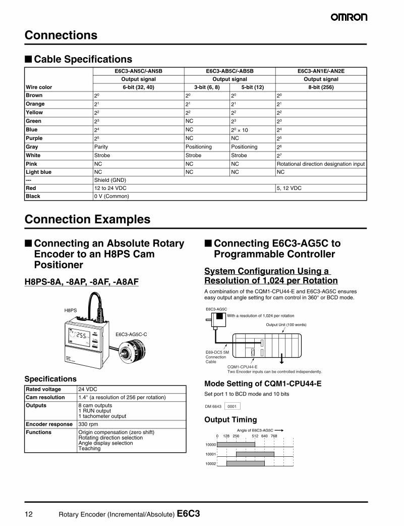
Connections
Cable Specifications
Connection Examples
Connecting an Absolute Rotary Encoder to an H8PS Cam Positioner
H8PS-8A, -8AP, -8AF, -A8AF
Specifications
Connecting E6C3-AG5C to Programmable Controller
System Configuration Using a Resolution of 1,024 per RotationA combination of the CQM1-CPU44-E and E6C3-AG5C ensures easy output angle setting for cam control in 360° or BCD mode.
Mode Setting of CQM1-CPU44-ESet port 1 to BCD mode and 10 bits
Output Timing
Wire color
E6C3-AN5C/-AN5B E6C3-AB5C/-AB5B E6C3-AN1E/-AN2E
Output signal Output signal Output signal
6-bit (32, 40) 3-bit (6, 8) 5-bit (12) 8-bit (256)
Brown 20 20 20 20
Orange 21 21 21 21
Yellow 22 22 22 22
Green 23 NC 23 23
Blue 24 NC 20 × 10 24
Purple 25 NC NC 25
Gray Parity Positioning Positioning 26
White Strobe Strobe Strobe 27
Pink NC NC NC Rotational direction designation input
Light blue NC NC NC NC
--- Shield (GND)
Red 12 to 24 VDC 5, 12 VDC
Black 0 V (Common)
Rated voltage 24 VDC
Cam resolution 1.4° (a resolution of 256 per rotation)
Outputs 8 cam outputs1 RUN output1 tachometer output
Encoder response 330 rpm
Functions Origin compensation (zero shift)Rotating direction selectionAngle display selectionTeaching
E6C3-AG5C-C
H8PS
Output Unit (100 words)
E6C3-AG5C
With a resolution of 1,024 per rotation
E69-DC5 5M Connection Cable
CQM1-CPU44-ETwo Encoder inputs can be controlled independently.
DM 6643 0001
Angle of E6C3-AG5C
0 128 256 512 640 768
10000
10001
10002

Rotary Encoder (Incremental/Absolute) E6C3 13
Ladder Program ExampleUse the CTBL instruction of the CQM1-CPU44-E to register a maxi-mum of eight comparison tables for output angle setting.
Example of DM Setting for Comparison Table
Note: An upper or lower limit can be set with integers in BCD modeand 5° increments in 360° mode. Subroutine numbers are setfor interrupt processing.
Internal Bits of CQM1-CPU44-E• Range Comparison Result
Each bit of the CQM1-CPU44-E CPU Unit's words AR 05 and AR06 turns ON only when the comparison range coincides with theangle of E6C3-AG5C. If it does not coincide, the bit turns (remains)OFF.
• Present Value ReadThe gray code signals of the E6C3-AG5C are automatically con-verted into BCD or 360° code signals and read through the CQM1-CPU44-E CPU Unit's words AR 232 and AR 234. The presentvalue can be used for ladder programs.
Note: For details on the CQM1-CPU44-E, refer to the CQM1 Pro-gramming Manual (W228).
Absolute Rotary Encoders
Connecting to CPM1A Using a Resolution of 720 per Rotation
Wiring Between E6C3-AG5C and CPM1A
Output Timing
Port 1 angle Word 232
Port 2 angle Word 234
AR0502
AR0501
AR0500
10002
10001 Output
10000
One scan ON25315
END (01)
CTBL (63)001001
DM0000
Select port 1 for table registration, comparison mode setting, and comparison-table first channel setting.
0000
0512
0000
0256
0768
0000
0128
0640
0000
0000
0000
0000
DM 0000
0001
0002
0003
0004
0005
0006
0007
0008
0009
0022
0023
Lower limit 1
Upper limit 1
Subroutine number 1
Lower limit 2
Upper limit 2
Subroutine number 2
Lower limit 3
Upper limit 3
Subroutine number 3
Lower limit 4
Upper limit 8
Subroutine number 8
Bit AR 0500
Bit AR 0501
Bit AR 0502
Not used.
Bit 7 0Port 1 comparison result
Port 2 comparison result
AR 05
AR 06
Comparison 1 result1: Conformity0: NonconformityComparison 8 result
Output signal from E6C3-AG5C Input signal to CPM1A
Brown (20) 00000
Orange (21) 00001
Yellow (22) 00002
Green (23) 00003
Blue (24) 00004
Purple (25) 00005
Gray (26) 00006
White (27) 00007
Pink (28) 00008
Light blue (29) 00009
E6C3-AG5C
CPM1A-20CD@-@
Angle of E6C3-AG5C
0 90 180 360 540 659
01000
01001
01002

14 Rotary Encoder (Incremental/Absolute) E6C3
00009
00008
00008
20009
20009
20008
20009
00007
00007
2000820007
20008
00006
00006
2000720006
20007
00005
00005
2000620005
20006
00004
00004
2000520004
20005
00003
00003
2000420003
20004
00002
00002
2000320002
20003
00001
00001
2000220001
20002
00000
00000
2000120000
20001
20302
20301
20300
01002
01001 Output
01000
(Always ON)25313
END (01)
BCD (24)200201
SUB (31)201
#0152202
BCMP (68)202
DM6200203
0000
0540
0090
0360
0180
0659
0000
0000
DM 6200
6201
6202
6203
6204
6205
6206
6231
Lower limit 1
Upper limit 1
Lower limit 2
Upper limit 2
Lower limit 3
Upper limit 3
Lower limit 4
Upper limit 16
Bit 20300
Bit 20301
Bit 20302
Not used.
Converts a BIN code signal (word 200) into a BCD code signal (word 201).
Subtracts 152 for a resolution of 720 per rotation.Nothing is subtracted for a resolution of 256 or 1,024 per rotation.Subtracts 76 for a resolution of 360 per rotation.
If the Encoder value (word 202) exists between DM 6200 (BCMP) and DM 6231 (the comparison table), the corresponding bit of word 203 turns ON.
Converts a gray code signal into a BIN code signal (word 200).
Ladder Program Example of DM Setting for Comparison Table

Rotary Encoder (Incremental/Absolute) E6C3 15
Precautions
Incremental and Absolute Encoders
Safety PrecautionsDo not impose voltage exceeding the rated voltage range on theE6C3, otherwise the E6C3 may be damaged.
Do not wire power lines or high-tension lines along with the powersupply lines of the E6C3 or the E6C3 may be damaged or malfunc-tion.
If the power supply has surge voltage, connect a surge suppressorbetween the positive and negative terminals of the power supply toabsorb the surge voltage. Also, in order to protect the E6C3 fromnoise, shorten the wires connected to the E6C3 as much as possible.
Unnecessary pulses are output at the time the E6C3 is turned ON orOFF. After turning ON the E6C3, be sure to wait 0.1 s before turningON the peripheral devices connected to the E6C3 and turn OFF theperipheral devices 0.1 s before turning OFF the E6C3.
Application Precautions
Mounting
Mounting Precautions• Be careful not to spray water or oil onto the E6C3.• The E6C3 consists of high-precision components. Handle with
utmost care and do not drop the E63C, otherwise malfunctioningmay result.
• When the E6C3 is used in reversed operation, pay utmost attentionto the mounting direction of the E6C3 and the directions of incre-ment and decrement rotation.
• To match phase Z of the E6C3 and the origin of the device to beconnected to the E6C3, conform the phase Z outputs while con-necting the device.
• Be careful not to impose an excessive load on the shaft if the shaftconnects to a gear.
• If the E6C3 is mounted with screws, the tightening torque must notexceed approximately 0.5 N·m.
• If the E6C3 is mounted to a panel, do not pull the cable with morethan a force of 30 N. Do not subject the E6C3 or the shaft to exces-sive shock.
• No shock must be given to the shaft or coupling. Therefore, do nothit the shaft or coupling with a hammer when inserting the shaft intothe coupling.
• When connecting the coupling, stay within the ranges shown below
• When connecting or disconnecting the coupling, do not impose anexcessive bending, pressing, or pulling force on the E6C3.
• When connecting the shaft of the E6C3 with a chain timing belt orgear, connect the chain timing belt or gear with the shaft via thebearing and coupling as shown in the following illustration.
• If the decentering or declination value exceeds the tolerance, anexcessive load imposed on the shaft may damage or shorten thelife of the E6C3.
Cable
30 N max.
Mounting plateMounting plate
Decentering tolerance
Declination tolerance
Displacement tolerance in the shaft direction
0.15 mm max.
2° max.
0.05 mm max.
Chain sprocket
Bearing
Coupling

16 Rotary Encoder (Incremental/Absolute) E6C3
Mounting Procedure
Life of Bearing
The following graph shows the (theoretical) life expectancy of the bearing with radial and thrust loads imposed on the bearing.
Wiring
Connecting• When extending the cable for Incremental Rotary Encoders, select
the kind of cable with care by taking the response frequency intoconsideration because the longer the cable is, the more the resid-ual voltage increases due to the resistance of the cable and thecapacitance between the wires. As a result, the waveform will bedistorted.We recommend the line driver output type model (E6C3-CWZ3XH)or the complementary output type model (E6C3-CWZ5GH) if thecable needs to be extended.In order to reduce inductive noise, the cable must be as short aspossible, especially when the signal is input to an IC.
• If the power supply has surge voltage, connect a surge suppressorbetween the positive and negative terminals of the power supply toabsorb the surge voltage.
• Unnecessary pulses are output at the time the E6C3 is turned ONor OFF. After turning ON the E6C3, be sure to wait 0.1 s beforeturning ON the peripheral devices connected to the E6C3 and turnOFF the peripheral devices 0.1 s before turning OFF the E6C3.
Cable Extension• The rise time of each output waveform will increase when the cable
is extended. This affects the phase difference characteristics ofphases A and B.
• The available length of cable varies with the response frequencyand noise. It is safer to limit the length of cable to 10 m maximum. Ifa longer cable of up to 100 m is required, use the line driver outputor complementary output model. (The maximum extension with theline driver output model is 100 m.)
Note: Recommended Cable:Cross section:0.2 mm2 with spiral shieldConductor resistance:92 Ω/km max. at 20°CInsulation resistance:5 MΩ/km min. at 20°C
• The rise time varies with the resistance of the cable and the kind ofcable as well as the length of the cable.
• The residual output voltage will increase according to the length ofthe cable.
Preventing MiscountingIf the operation of the E6C3 is stopped near a signal rising or falling edge, a wrong pulse may be generated, in which case the E6C3 will miscount. In such a case, use an increment-decrement counter to prevent miscounting.
1 Insert the shaft into the coupling.
2 Secure the Rotary Encoder.
3 Secure the coupling.
4 Connect the power and I/O lines.
5
Model Maximum insertion lengthE69-C08B/E69-C68B 6.8 mm
Model Tightening torqueE69-C08/E69-C68B 0.44 N ⋅ m
Do not secure the coupling and shaft with screws at this stage.
Refer to the following table for the maximum insertion length of the shaft into the coupling.
Be sure to turn off the Rotary Encoder when connecting the lines.
Turn on the Rotary Encoder and check the output.
3.5
3.0
2.5
2.0
1.5
1.0
0.5
010 20 30 40 50 60 70 80 90 100
Radial load Wr (N)
Wa:10N
Encoder
Wr: Radial loadWs: Thrust load
Wa:20N
Wa:30N
Wa:40N
Wa:50N
Wa:60N
Wr
Ws
Shaft
Life
(×
1010
rev
olut
ions
)

Rotary Encoder (Incremental/Absolute) E6C3 17
Extension of Line Driver Output• Be sure to use a shielded twisted-pair cable to extend a line driver
cable.Recommended cable: Tachii Electric Wire Co., TKVVBS4P 02A
• Use an RS-422A Receiver for the receiver side.• The twisted-pair wires as shown in the following illustration are suit-
able for RS-422A signal transmission. Normal mode noise can beeliminated by twisting the wires because the generated electricalforces on the lines cancel each other.
• Be sure the E6C3 is supplied with 5 VDC when a line driver outputis used. There will be an approximately 1-V voltage drop if the cablelength is 100 m.
Input to More than One Counter from Encoder (with Voltage Output)Use the following formula to obtain the number of counters to be con-nected to a single E6C3.
E:Voltage supplied to E6C3V:Minimum input voltage of the counterR1:Input resistance of the CounterR2:Output resistance of the E6C3
Twisted-pair wires
Number of counters (N) = R1 (E−V)V × R2
Encoder output stage
Counter Counter
Connectable number: N
0 V

18 Rotary Encoder (Incremental/Absolute) E6C3
DimensionsUnit: mm (inch)
Rotary Encoder
E6C3-CWZ@@H
E6C3-A@5@E6C3-AN@E
Note: E69-C08B Coupling is sold separately.
8 dia. +0 −0.018
5 dia. oil-proof PVC, shielded 5-conductor cable (8-conductor for line driver)(conductor cross-section: 0.2 mm2; insulation diameter: 1.1 mm)Standard length: 1 m
6
8.86
12 dia.
50 dia.
1
1
5D cut: Phase-Z postion (range: ±15°)
1040 dia.±0.1
10
Three, M4 holes Depth: 5
120°±0.1
120°±0.1
30 dia.+0 −0.021
(15)
3820
(58)
8 dia.+0 −0.018
6 dia. oil-proof PVC, shielded 12-conductor cable(conductor cross-section: 0.2 mm2; insulation diameter: 1.1 mm)Standard length: 1 m
6
8.86
50 dia.
1
5D cut: Phase-Z postion (range: ±15°)
1040 dia.±0.1
10
120°±0.1
120°±0.1
30 dia.+0 −0.021
(15)
3820
(58)
Three, M4 holes Depth: 5

Rotary Encoder (Incremental/Absolute) E6C3 19
E6C3-AG5C-C
Note: E69-C08B Coupling is sold separately.
Accessories (Order Separately)
Extension CableE69-DF5
Note: The Cable can be extended up to 100 m for connecting the H8PS Cam Positioner.
E69-C08B
E69-C68B (With Ends of Different Diameter)
Hirose ElectricRP13A-12PD-13SC
8 dia.+0 −0.018
6-dia. oil-proof PVC, shielded 12-conductor cable(conductor cross-section: 0.2 mm2; insulation diameter: 1.1 mm)Standard length: 1 m
6
8.86
50 dia.
1
5D cut: Phase-Z postion (range: ±15°)
1040 dia.±0.1
10
120°±0.1
120°±0.1
30 dia.+0 −0.021
(15)
3820
(58)
37
Three, M4 holes Depth: 5
16.9 dia. 16.9 dia.
34.6
(See note 2.) (See note 3.)(See note 1.)
375,000
Note 1: 6-dia. oil-proof PVC, shielded 12-conductor cable (conductor cross-section: 0.2 mm2; insulation diameter: 1.1 mm); standard length: 5 m
2: Connects to the connector of the E6C3-AG5C-C.3: Connects to the H8PR Rotary Positioner and H8PS Cam Positioner.
19 dia.8H8 dia.8H8 dia.
Note: Material: Glass-reinforced PBT
Four, M4 hexagon set screws
19 dia.8H8 dia.6H8 dia.
Brass bushing
Four, M4 hexagon socket heat setscrews
Note: The coupling is made of glass-reinforced PBT.

20 Rotary Encoder (Incremental/Absolute) E6C3
Flanges
Servo Mounting BracketE69-2 (A Set of Three)
120°
30 dia.
68 dia.±0.2Three, M5
Panel
120°
40±0.1 dia.56 dia.
30.2±0.1 dia.
Material: SPCC (t=3.2) Material: SPCC (t=3.2)
Four, 4.5 dia.
Three, 4.5 dia, M4 screw-head holes
Four, R3
Three, 4.5 dia, M4 screw-head holes
30.2±0.1 dia.40±0.1 dia.
E69-FCA03 E69-FCA04 Mounting Bracket Installation
5.5-dia. hole
Two, C1

Rotary Encoder (Incremental/Absolute) E6C3 21
Certain Terms and Conditions of Sale1. Offer; Acceptance. These terms and conditions (these "Terms") are deemed
part of all catalogs, manuals or other documents, whether electronic or in writ-ing, relating to the sale of goods or services (collectively, the "Goods") byOmron Electronics LLC and its subsidiary companies ("Seller"). Seller herebyobjects to any terms or conditions proposed in Buyer's purchase order or otherdocuments which are inconsistent with, or in addition to, these Terms. Pleasecontact your Omron representative to confirm any additional terms for salesfrom your Omron company.
2. Prices. All prices stated are current, subject to change without notice bySeller. Buyer agrees to pay the price in effect at time of shipment.
3. Discounts. Cash discounts, if any, will apply only on the net amount ofinvoices sent to Buyer after deducting transportation charges, taxes andduties, and will be allowed only if (i) the invoice is paid according to Seller'spayment terms and (ii) Buyer has no past due amounts owing to Seller.
4. Orders. Seller will accept no order less than $200 net billing. 5. Governmental Approvals. Buyer shall be responsible for, and shall bear all
costs involved in, obtaining any government approvals required for the impor-tation or sale of the Goods.
6. Taxes. All taxes, duties and other governmental charges (other than generalreal property and income taxes), including any interest or penalties thereon,imposed directly or indirectly on Seller or required to be collected directly orindirectly by Seller for the manufacture, production, sale, delivery, importation,consumption or use of the Goods sold hereunder (including customs dutiesand sales, excise, use, turnover and license taxes) shall be charged to andremitted by Buyer to Seller.
7. Financial. If the financial position of Buyer at any time becomes unsatisfactoryto Seller, Seller reserves the right to stop shipments or require satisfactorysecurity or payment in advance. If Buyer fails to make payment or otherwisecomply with these Terms or any related agreement, Seller may (without liabilityand in addition to other remedies) cancel any unshipped portion of Goods soldhereunder and stop any Goods in transit until Buyer pays all amounts, includ-ing amounts payable hereunder, whether or not then due, which are owing to itby Buyer. Buyer shall in any event remain liable for all unpaid accounts.
8. Cancellation; Etc. Orders are not subject to rescheduling or cancellationunless Buyer indemnifies Seller fully against all costs or expenses arising inconnection therewith.
9. Force Majeure. Seller shall not be liable for any delay or failure in deliveryresulting from causes beyond its control, including earthquakes, fires, floods,strikes or other labor disputes, shortage of labor or materials, accidents tomachinery, acts of sabotage, riots, delay in or lack of transportation or therequirements of any government authority.
10. Shipping; Delivery. Unless otherwise expressly agreed in writing by Seller:a. Shipments shall be by a carrier selected by Seller;b. Such carrier shall act as the agent of Buyer and delivery to such carrier
shall constitute delivery to Buyer;c. All sales and shipments of Goods shall be FOB shipping point (unless oth-
erwise stated in writing by Seller), at which point title to and all risk of loss ofthe Goods shall pass from Seller to Buyer, provided that Seller shall retain asecurity interest in the Goods until the full purchase price is paid by Buyer;
d. Delivery and shipping dates are estimates only. e. Seller will package Goods as it deems proper for protection against normal
handling and extra charges apply to special conditions.11. Claims. Any claim by Buyer against Seller for shortage or damage to the
Goods occurring before delivery to the carrier must be presented in writing toSeller within 30 days of receipt of shipment and include the original transporta-tion bill signed by the carrier noting that the carrier received the Goods fromSeller in the condition claimed.
12. Warranties. (a) Exclusive Warranty. Seller's exclusive warranty is that theGoods will be free from defects in materials and workmanship for a period oftwelve months from the date of sale by Seller (or such other period expressedin writing by Seller). Seller disclaims all other warranties, express or implied.(b) Limitations. SELLER MAKES NO WARRANTY OR REPRESENTATION,EXPRESS OR IMPLIED, ABOUT NON-INFRINGEMENT, MERCHANTABIL-ITY OR FITNESS FOR A PARTICULAR PURPOSE OF THE GOODS.BUYER ACKNOWLEDGES THAT IT ALONE HAS DETERMINED THAT THEGOODS WILL SUITABLY MEET THE REQUIREMENTS OF THEIRINTENDED USE. Seller further disclaims all warranties and responsibility ofany type for claims or expenses based on infringement by the Goods or other-wise of any intellectual property right. (c) Buyer Remedy. Seller's sole obliga-tion hereunder shall be to replace (in the form originally shipped with Buyerresponsible for labor charges for removal or replacement thereof) the non-complying Good or, at Seller's election, to repay or credit Buyer an amountequal to the purchase price of the Good; provided that in no event shall Sellerbe responsible for warranty, repair, indemnity or any other claims or expensesregarding the Goods unless Seller's analysis confirms that the Goods wereproperly handled, stored, installed and maintained and not subject to contami-nation, abuse, misuse or inappropriate modification. Return of any goods byBuyer must be approved in writing by Seller before shipment. Seller shall notbe liable for the suitability or unsuitability or the results from the use of Goodsin combination with any electrical or electronic components, circuits, systemassemblies or any other materials or substances or environments. Anyadvice, recommendations or information given orally or in writing, are not to beconstrued as an amendment or addition to the above warranty.
13. Damage Limits; Etc. SELLER SHALL NOT BE LIABLE FOR SPECIAL, INDI-RECT OR CONSEQUENTIAL DAMAGES, LOSS OF PROFITS OR PRODUC-TION OR COMMERCIAL LOSS IN ANY WAY CONNECTED WITH THEGOODS, WHETHER SUCH CLAIM IS BASED IN CONTRACT, WARRANTY,NEGLIGENCE OR STRICT LIABILITY. Further, in no event shall liability ofSeller exceed the individual price of the Good on which liability is asserted.
14. Indemnities. Buyer shall indemnify and hold harmless Seller, its affiliates andits employees from and against all liabilities, losses, claims, costs andexpenses (including attorney's fees and expenses) related to any claim, inves-tigation, litigation or proceeding (whether or not Seller is a party) which arisesor is alleged to arise from Buyer's acts or omissions under these Terms or inany way with respect to the Goods. Without limiting the foregoing, Buyer (atits own expense) shall indemnify and hold harmless Seller and defend or settleany action brought against Seller to the extent that it is based on a claim thatany Good made to Buyer specifications infringed intellectual property rights ofanother party.
15. Property; Confidentiality. The intellectual property embodied in the Goods isthe exclusive property of Seller and its affiliates and Buyer shall not attempt toduplicate it in any way without the written permission of Seller. Notwithstand-ing any charges to Buyer for engineering or tooling, all engineering and toolingshall remain the exclusive property of Seller. All information and materialssupplied by Seller to Buyer relating to the Goods are confidential and propri-etary, and Buyer shall limit distribution thereof to its trusted employees andstrictly prevent disclosure to any third party.
16. Miscellaneous. (a) Waiver. No failure or delay by Seller in exercising any rightand no course of dealing between Buyer and Seller shall operate as a waiverof rights by Seller. (b) Assignment. Buyer may not assign its rights hereunderwithout Seller's written consent. (c) Amendment. These Terms constitute theentire agreement between Buyer and Seller relating to the Goods, and no pro-vision may be changed or waived unless in writing signed by the parties. (d) Severability. If any provision hereof is rendered ineffective or invalid, suchprovision shall not invalidate any other provision. (e) Setoff. Buyer shall haveno right to set off any amounts against the amount owing in respect of thisinvoice. (f) As used herein, "including" means "including without limitation".
Certain Precautions on Specifications and Use1. Suitability of Use. Seller shall not be responsible for conformity with any stan-
dards, codes or regulations which apply to the combination of the Good in theBuyer's application or use of the Good. At Buyer's request, Seller will provideapplicable third party certification documents identifying ratings and limitationsof use which apply to the Good. This information by itself is not sufficient for acomplete determination of the suitability of the Good in combination with theend product, machine, system, or other application or use. The following aresome examples of applications for which particular attention must be given.This is not intended to be an exhaustive list of all possible uses of this Good,nor is it intended to imply that the uses listed may be suitable for this Good: (i) Outdoor use, uses involving potential chemical contamination or electrical
interference, or conditions or uses not described in this document. (ii) Energy control systems, combustion systems, railroad systems, aviation
systems, medical equipment, amusement machines, vehicles, safety equipment, and installations subject to separate industry or governmentregulations.
(iii) Systems, machines and equipment that could present a risk to life orproperty. Please know and observe all prohibitions of use applicable tothis Good.
NEVER USE THE PRODUCT FOR AN APPLICATION INVOLVING SERIOUSRISK TO LIFE OR PROPERTY WITHOUT ENSURING THAT THE SYSTEMAS A WHOLE HAS BEEN DESIGNED TO ADDRESS THE RISKS, AND THATTHE SELLER'S PRODUCT IS PROPERLY RATED AND INSTALLED FORTHE INTENDED USE WITHIN THE OVERALL EQUIPMENT OR SYSTEM.
2. Programmable Products. Seller shall not be responsible for the user's pro-gramming of a programmable Good, or any consequence thereof.
3. Performance Data. Performance data given in this catalog is provided as aguide for the user in determining suitability and does not constitute a warranty.It may represent the result of Seller's test conditions, and the user must corre-late it to actual application requirements. Actual performance is subject to theSeller's Warranty and Limitations of Liability.
4. Change in Specifications. Product specifications and accessories may bechanged at any time based on improvements and other reasons. It is our prac-tice to change part numbers when published ratings or features are changed,or when significant construction changes are made. However, some specifica-tions of the Good may be changed without any notice. When in doubt, specialpart numbers may be assigned to fix or establish key specifications for yourapplication. Please consult with your Seller's representative at any time to con-firm actual specifications of purchased Good.
5. Errors and Omissions. The information in this catalog has been carefullychecked and is believed to be accurate; however, no responsibility is assumedfor clerical, typographical or proofreading errors, or omissions.

22 Rotary Encoder (Incremental/Absolute) E6C3
OMRON ON-LINEGlobal - http://www.omron.comUSA - http://www.omron.com/oeiCanada - http://www.omron.ca
Cat. No. F058-E3-01 Printed in USA
OMRON CANADA, INC.885 Milner AvenueToronto, Ontario M1B 5V8
416-286-6465
OMRON ELECTRONICS LLCOne Commerce DriveSchaumburg, IL 60173
847-843-7900For US technical support or other inquiries:
800-556-676610/03 Specifications subject to change without notice
Complete “Terms and Conditions of Sale” for product purchase and use are on Omron’s websiteat www.omron.com/oei – under the “About Us” tab, in the Legal Matters section.
ALL DIMENSIONS SHOWN ARE IN MILLIMETERS.To convert millimeters into inches, multiply by 0.03937. To convert grams into ounces, multiply by 0.03527.