e04 riduttori e motoriduttori coassiali coaxial gear ... · riduttori e motoriduttori coassiali...
TRANSCRIPT

ProductsMedia No. 4002
E04Riduttori e motoriduttori coassialiCoaxial gear reducers and gearmotors
Edition December 2011

Indice Contents
1 Simboli e unità di misura 4 1 Symbols and units of measure 4
2 Caratteristiche 5 2 Specifications 5
3 Designazione 13 3 Designation 13
4 Fattore di servizio fs 14 4 Service factor fs 14
5 Scelta 15 5 Selection 15
6 Potenze e momenti torcenti nominali (riduttori)
19 6 Nominal powers and torques (gear redu-cers)
19
7 Esecuzioni, dimensioni, forme costrutti-ve e quantità di lubrificante
26 7 Designs, dimensions, mounting positions and lubricant quantities
26
8 Programma di fabbricazione (motoridut-tori)
28 8 Selection tables 28
9 Esecuzioni, dimensioni, forme costrutti-ve e quantità di lubrificante
50 9 Designs, dimensions, mounting positions and lubricant quantities
50
10 Gruppi riduttori e motoriduttori 52 10 Combined gear reducer and gearmotor units
52
11 Dimensioni gruppi 52 11 Combined unit dimensions 52
12 Carichi radiali Fr1 sull'estremità d'albero veloce
54 12 Radial loads Fr1 on high speed shaft end 54
13 Carichi radiali Fr2 o assiali Fa2 sull'estre-mità d'albero lento
54 13 Radial loads Fr2 on axial loads Fa2 on low speed shaft end
54
14 Dettagli costruttivi e funzionali 66 14 Structural and operation details 66
15 Installazione e manutenzione 68 15 Installation and maintenance 68
16 Accessori ed esecuzioni speciali 71 16 Accessories and non-standard designs 71
17 Formule tecniche 77 17 Technical formulae 77
Indice delle revisioni 78 Index of revisions 78

3E04 December 2011
Riduttori e motoriduttori coassiali
Gruppi riduttorie motoriduttori (combinati)
Coaxial gear reducers and gearmotors
Combined gear reducerand gearmotor units
2I, 3I 32 ... 41*a 2, 3 ingranaggi cilindrici
with 2, 3 cylindrical gear pairs
2I, 3I 50 ... 180a 2, 3 ingranaggi cilindrici
with 2, 3 cylindrical gear pairs
* solo motoriduttori * gearmotors only
MR 3I + R 2I, 3I MR 3I + MR 2I, 3I

4 E04 December 2011
1 - Simboli e unità di misura 1 - Symbols and units of measureSimboli in ordine alfabetico, con relative unità di misura, impiegati nel catalogo e nelle formule.
Symbols used in the catalogue and formulae, in alphabetical order, with relevant units of measure.
Simbolo Espressione Unità di misura Note Symbol Definition Units of measure Notes Nel catalogo Nelle formule In the In the formulae catalogue Sistema Tecnico Sistema SI1)
Technical System SI1) System
dimensioni, quote dimensions mm – a accelerazione acceleration – m/s2
d diametro diameter – m f frequenza frequency Hz Hz fs fattore di servizio service factor f t fattore termico thermal factor F forza force – kgf N2) 1 kgf ≈ 9,81 N ≈ 0,981 daN Fr carico radiale radial load daN – Fa carico assiale axial load daN – g accelerazione di gravità acceleration of gravity – m/s2 val. norm. 9,81 m/s2 normal value 9,81 m/s2
G peso (forza peso) weight (weight force) – kgf N Gd2 momento dinamico dynamic moment – kgf m2
–
i rapporto di trasmissione transmission ratio i =
n1
n2
I corrente elettrica electric current – A J momento d’inerzia moment of inertia kg m2 – kg m2
Lh durata dei cuscinetti bearing life h – m massa mass kg kgf s2/m kg3)
M momento torcente torque daN m kgf m N m 1 kgf m ≈ 9,81 N m ≈ 0,981 daN m
n velocità angolare speed min-1 giri/min – 1 min-1 ≈ 0,105 rad/s rev/min P potenza power kW CV W 1 CV ≈ 736 W ≈ 0,736 kW P t potenza termica thermal power kW – r raggio radius – m
R rapporto di variazione variation ratio R =
n2 max
n2 min
s spazio distance – m t temperatura Celsius Celsius temperature °C – t tempo time s s min 1 min = 60 s h 1 h = 60 min = 3 600 s d 1 d = 24 h = 86 400 s U tensione elettrica voltage V V v velocità velocity – m/s W lavoro, energia work, energy MJ kgf m J4)
z frequenza di avviamento frequency of starting avv./h –
starts/h � accelerazione angolare angular acceleration – rad/s2
� rendimento efficiency �s rendimento statico static efficiency � coefficiente di attrito friction coefficient � angolo piano plane angle ° rad 1 giro = 2 � rad 1 rev = 2 � rad 1° = �
rad � velocità angolare angular velocity – – rad/s 1 rad/s ≈ 9,55 min-1
Indici aggiuntivi e altri segni Additional indexes and other signs
1) SI è la sigla del Sistema Internazionale di Unità, definito ed approvato dalla Conferenza Generale dei Pesi e Misure quale unico sistema di unità di misura.
Ved. CNR UNI 10 003-84 (DIN 1 301-93 NF X 02.004, BS 5 555-93, ISO 1 000-92). UNI: Ente Nazionale Italiano di Unificazione. DIN: Deutscher Normenausschuss (DNA). NF: Association Française de Normalisation (AFNOR). BS: British Standards Institution (BSI). ISO: International Organization for Standardization.2) Il newton [N] è la forza che imprime a un corpo di massa 1 kg l’accelerazione di 1 m/s2.3) Il kilogrammo [kg] è la massa del campione conservato a Sèvres (ovvero di 1 dm3 di
acqua distillata a 4 °C).4) Il joule [J] è il lavoro compiuto dalla forza di 1 N quando si sposta di 1 m.
1) SI are the initials of the International Unit System, defined and approved by the General Conference on Weights and Measures as the only system of units of measure.
Ref. CNR UNI 10 003-84 (DIN 1 301-93 NF X 02.004, BS 5 555-93, ISO 1 000-92). UNI: Ente Nazionale Italiano di Unificazione. DIN: Deutscher Normenausschuss (DNA). NF: Association Française de Normalisation (AFNOR). BS: British Standards Institution (BSI). ISO: International Organization for Standardization.2) Newton [N] is the force imparting an acceleration of 1 m/s2 to a mass of 1 kg.3) Kilogramme [kg] is the mass of the prototype kept at Sèvres (i.e. 1 dm3 of distilled
water at 4 °C).4) Joule [J] is the work done when the point of application of a force of 1 N is displaced
through a distance of 1 m.
Ind. Espressione Definition
max massimo maximum min minimo minimum N nominale nominal 1 relativo all’asse veloce (entrata) relating to high speed shaft (input) 2 relativo all’asse lento (uscita) relating to low speed shaft (output) � da ... a from ... to ≈ uguale a circa approximately equal to � maggiore o uguale a greater than or equal to � minore o uguale a less than or equal to
180

55E04 December 2011
2 - Caratteristiche 2 - SpecificationsUniversal mounting (patented; lower feet, upper feet, B5 flange with low speed shaft end shifted forward)Closer intermediate size steps (for size pairs, standard and streng thened, only one housing and many components in common, changing only the ones allowing higher performances of greater size; improved modular construction) offering sizes closer to every application need and maintaining nearly the same component number for maximum economy of solution; same mounting dimensions for the size pairsRigid and precise single-piece cast iron housing (excluding sizes 32 ... 41)Generously proportioned bearings of low speed shaft (bearings and shaft) in order to withstand high loads on shaft endPossibility of mounting large size motorsPossibility of square flanges for servomotorsManufacturing and product management flexibilityHigh manufacturing quality standardMinimum maintenance requirementsStandard motor to IECHigh, reliable and tested performancesPinion of final reduction with three bearings (excluding sizes32 ... 41) in order to ensure best meshing conditions (no overhang wheel; maximum rigidity and overloading capacity, maximum reduction of noise level)This range of gear reducers and gearmotors combines and exalts the traditional qualities of coaxial gear reducers – compactness, economy –, with the ones deriving from modern design, manufac-turing and operating criteria – strength and suitability also for heaviest applications, universality and ease of application, wide range of sizes, service – the advantages typically associated with high quality gear reducers produced in large series.
Fissaggio universale (brevettato; piedi inferiori, piedi superiori, flan-gia B5 con estremità d’albero lento spostata in avanti)Scalamento infittito delle grandezze (per le grandezze doppie – normale e rinforzata – una sola carcassa e molti componenti in comune, cambiano solo quelli che rendono disponibili le maggiori prestazioni della grandezza superiore; modularità spinta) allo scopo di offrire grandezze più vicine alle esigenze di ogni applicazione e studiato per mantenere quasi immutato il numero dei compo-nenti per la massima economicità della soluzione; di mensioni di fissaggio uguali per le grandezze doppieCarcassa monolitica (escluse grand. 32 ... 41) di ghisa, rigida e precisaSopportazione asse lento (cuscinetti e albero) ampiamente di mensionata per sopportare elevati carichi sull’estremità d’alberoPossibilità di montare motori di grandezza notevolePossibilità di flange quadrate per servomotoriFlessibilità di fabbricazione e di gestioneElevata classe di qualità di fabbricazioneManutenzione ridottissimaMotore normalizzato IECPrestazioni elevate, affidabili e collaudatePignone riduzione finale con tre sopporti (escluse grand. 32 ... 41) per assicurare le migliori condizioni di ingranamento (nessuna ruota a sbalzo; massima rigidezza e sovraccaricabilità, massima si lenziosità)Questa serie di riduttori e motoriduttori unisce, esaltate, le classiche caratteristiche dei riduttori coassiali – compattezza, economicità – con quelle derivanti da una moderna concezione progettuale, di fabbricazione e gestione – robustezza e idoneità anche ai servizi più gravosi, universalità e facili tà d’applicazione, ampia gamma di grandezze, servizio – tipiche dei riduttori di qualità costruiti in grande serie.
a - RiduttoreParticolarità costruttiveLe principali caratteristiche sono:– fissaggio universale (brevettato) con piedi inferiori e superiori e
flangia B5 integrali alla carcassa (escluse le grandezze 32 ... 41 per le quali il fissaggio è o con i piedi o con flangia, sempre integrali alla carcassa);
– estremità d’albero lento spostata in avanti (esclusa grandezza 40) rispetto al piano flangia, per minore sbalzo a parità di posi-zione del carico radiale esterno;
– concezione moderna secondo il nuovo sistema modulare Rossi (modularità spinta a livello sia di componenti sia di prodotto finito);
– massima compattezza e ingombri ridotti – e uguali tra 2I e 3I –
a - Gear reducerStructural featuresMain specifications are:– universal mounting (patented) with lower and upper feet and
B5 flange integral with housing (excluding sizes 32 ... 41 whose mounting is either with feet or with flange always integral with housing);
– low speed shaft end shifted forward (excluding size 40) compa-red to flange plane, for smaller overhang having same position of external radial load;
– modern conception according to Rossi new modular system (improved modular construction both for component parts and assembled product);
Fissaggio con piedi - Foot mounting Fissaggio con flangia - Flange mounting
Altezza d’asse «normale» (H)«Standard» shaft height (H)
Altezza d’asse «bassa» (H0), in gombro minimo«Low» shaft height (H0), minimum overall dimensions
Adattatore per intercambiabilitàAdaptor for interchangeability
Flangia normale (fori passanti) ed estremità d’albero lento spostata in avanti per sbalzo minimoStandard flange (through holes) and low speed shaft end shifted forward for minimum overhang
Flangia maggiorata (fori passanti) ed estremità d’albero lento con battuta coincidente con il piano flangiaOversized flange (through holes) and low speed shaft end having shoulder coinciding with flange plane
1) H, H0 altezza d’asseD Ø estremità d’albero lentoMN2 momento torcente nominale [daN m]Fr2 carico radiale [daN]
1) H, H0 shaft heightD Ø low speed shaft endMN2 nominal torque [daN m]Fr2 radial load [daN]

6 E04 December 2011
2 - Caratteristiche 2 - Specifications
soprattutto in senso longitudinale; alberi lento e veloce coassiali ad esclusione delle grandezze 140 ... 180 per le quali sono leg-germente disassati (ved. capp. 7 e 9);
– carcassa monolitica (escluse le grandezze 32 ... 41) di ghisa 200 UNI ISO 185 con nervature di irrigidimento ed elevata capienza di lubrificante;
– riduttore dimensionato in ogni parte per essere equipaggiato con motori di grandezza notevole, per trasmettere elevati momenti torcenti nominali e massimi, per sopportare elevati carichi sulle estremità d’albero lento e veloce;
– cuscinetti volventi assi intermedi a sfere o a rulli cilindrici, ben di mensionati per ogni condizione;
– cuscinetti volventi asse lento ampiamente dimensionati per sopportare forti carichi sull’estremità d’albero lento (anch’esso ampiamente dimensionato allo stesso scopo);
– pignone ultima riduzione con tre sopporti (escluse grand. 32 ... 41)
per assicurare le migliori condizioni di ingranamento (nessuna ruota a sbalzo, massima rigidezza e sovraccaricabilità, massima silenziosità);
– riduttori: lato entrata con flangia lavorata e con fori (escluse gran-dezze 32 e 40);
– motoriduttori: motore normalizzato IEC con il pignone montato direttamente sull’estremità d’albero;
– estremità d’albero con linguetta e foro filettato in testa;– dimensioni normalizzate e corrispondenza alle norme;– lubrificazione a grasso o a bagno d’olio; a grasso sintetico per
grandezze 32 ... 41 o olio sintetico grandezze 50 ... 81 tutte fornite complete di lubrificante per lubrificazione «a vita» e con un tappo (grandezze 32 ... 64) o due tappi (grandezze 80 e 81); a olio sintetico o minerale (cap. 15) con tappo di carico con valvola, scarico e livello (grandezze 100 ... 180); tenuta stagna;
– verniciatura: protezione esterna con vernice a polveri epossidiche (grandezze 32 ... 41) o con vernice sintetica (grandezze 50 ... 180) idonee a resistere ai normali ambienti industriali e a consentire ulte-riori finiture con vernici sintetiche; colore blu RAL 5010 DIN 1843; protezione interna con vernice a polveri epossidiche (grandezze 32 ... 41) o epossidica (grandezze 50 ... 81) idonee a resistere agli oli sintetici o con vernice sintetica (grandezze 100 ... 180) idonea a resistere agli oli minerali o sintetici a base di polialfaolefine;
– possibilità di realizzare gruppi riduttori e motoriduttori ad elevato rapporto di trasmissione;
– esecuzioni speciali: ved. cap. 16.
Rotismo:– a 2, 3 (5, 6 nei gruppi) ingranaggi cilindrici;– 7 grandezze con interasse riduzione finale secondo serie R 10
(32 ... 125, di cui 6 doppie: normale e rinforzata), 3 grandezze con interasse riduzione finale secondo serie R 20 (140 ... 180), per un totale di 16 grandezze;
– rapporti di trasmissione nominali secondo serie R 10 (6,3 ... 6 300) per i riduttori;
– velocità di uscita prossime ai numeri normali serie R 20 (0,45 ... 710 min-1) per i motoriduttori;
– ingranaggi di acciaio 16 CrNi4 o 20 MnCr5 secondo la grandezza e 18 NiCrMo5 UNI 7846-78 cementati/temprati;
– ingranaggi cilindrici a dentatura elicoidale con profilo rettificato;– capacità di carico del rotismo calcolata a rottura e a pitting.
Norme specifiche:– rapporti di trasmissione nominali e dimensioni principali secondo i
numeri normali UNI 2016 (DIN 323-74, NF X 01.001, BS 2045-65, ISO 3-73);
– profilo dentatura secondo UNI 6587-69 (DIN 867-86, NF E 23.011, BS 436.2-70, ISO 53-74);
– altezze d’asse secondo UNI 2946-68 (DIN 747-76, NF E 01.051,BS 5186-75, ISO 496-73);
– flange di fissaggio B14 e B5 derivate da UNEL 13501-69 (DIN 42948-65, IEC 72.2);
– fori di fissaggio serie media secondo UNI 1728-83 (DIN 69-71, NFE 27.040, BS 4186-67, ISO/R 273);
– estremità d’albero cilindriche (lunghe o corte) secondo UNI ISO
– maximum compactness and reduced overall dimensions – and equal for 2I and 3I – especially in longitudinal direction; coaxial low and high speed shafts excluding sizes 140 ... 180 for which they are slightly misaligned (see ch. 7 and 9);
– single-piece cast iron housing 200 UNI ISO 185 (excluding sizes 32 ... 41) with stiffening ribs and high lubricant capacity;
– gear reducer overall sized so as to accept particularly powerful motors, to permit the transmission of high nominal and maximum torques and to withstand high loads on high and low speed shaft ends;
– cylindrical roller or ball bearings on intermediate shafts duly sized for every condition;
– bearings of low speed shaft generously proportioned in order to withstand high loads on low speed shaft end (which is also pro-portioned for the same purpose);
– pinion of final reduction with three bearings (excluding sizes
32 ... 41) in order to ensure best meshing conditions (no overhang wheel, maximum rigidity and overloading capacity, maximum reduction of noise level);
– gear reducers: input face having machined flange and holes (excluding sizes 32 and 40);
– gearmotors: standard motor to IEC with pinion directly mounted onto shaft end;
– shaft end with parallel key and tapped butt-end hole;– standard dimensions and compliance with standards;– grease or oil-bath lubrication; with synthetic grease for sizes 32 ... 41
or synthetic oil sizes 50 ... 81 all supplied filled with lubricant for lubrication «for life» and with a plug (sizes 32 ... 64) or two plugs (sizes 80 and 81); with synthetic or mineral oil (ch. 15) with filler plug with valve, drain and level plug (sizes 100 ... 180); sealed;
– paint: external coating in epoxy powder paint (sizes 32 ... 41) or synthetic paint (sizes 50 ... 180) appropriate for resistance to normal industrial environments and suitable for the application of further coats of synthetic paints; colour blue RAL 5010 DIN 1843; internal protection with epoxy powder paint (sizes 32 ... 41) or epoxy paint (sizes 50 ... 81) suitable to resist synthetic oils or with synthetic paint (sizes 100 ... 180) appropriate to resist mineral or polyalphaolefines synthetic oils;
– possibility of obtaining combined gear reducer and gearmotor units providing high transmission ratios;
– non-standard designs: see ch. 16.
Train of gears:– 2, 3 cylindrical gear pairs (5, 6 in combined units);– 7 sizes with final reduction centre distance to R 10 series
(32 ... 125, with 6 size pairs: standard and strengthened); 3 sizes with final reduction centre distance to R 20 series (140 ... 180) for a total of 16 sizes;
– nominal transmission ratios to R 10 series (6,3 ... 6 300) for gear reducers;
– output speeds close to standard number R 20 series (0,45 ... 710 min-1) for gearmotors;
– casehardened and hardened gear pairs in 16 CrNi4 or 20 MnCr5 steel depending on size and 18 NiCrMo5 steel, according to UNI 7846-78;
– helical toothed gear pairs with ground profile;– gears load capacity calculated for tooth breakage and pitting.
Specific standards:– nominal transmission ratios and main dimensions according to
UNI 2016 standard numbers (DIN 323-74, NF X 01.001, BS 2045-65,ISO 3-73);
– tooth profiles to UNI 6587-69 (DIN 867-86, NF E 23.011, BS 436.2-70, ISO 53-74);
– shaft heights to UNI 2946-68 (DIN 747-76, NF E 01.051, BS 5186-75, ISO 496-73);
– fixing flanges B14 and B5 taken from UNEL 13501-69 (DIN 42948-65, IEC 72.2);
– medium series fixing holes to UNI 1728-83 (DIN 69-71, NF E 27.040, BS 4186-67, ISO/R 273);
– cylindrical shaft ends (long or short) to UNI ISO 775-88 (DIN 748,
CuscinettoBearing
Grandezza - Size
32 40 41 50 51 63 64 80 81 100 101 125 126 140 160 180
lato esternoexternal sidelato internointernal side
6203 6204 6205 6206 6206E 6207E 6208E 6308 NJ210EC 6310 NJ212EC 30214 32016 32018 32021 32024
6201 6004 6203 6204 6204E 6205E 6206E 6306 NJ207EC 6308 NJ210EC 30212 32014 32016 32018 32021

77E04 December 2011
2 - Caratteristiche 2 - Specifications
NF E 22.05.051, BS 4506-70, ISO/R775) with tapped butt-end hole to UNI 9321 (DIN 332 BI. 2-70, NF E 22.056) excluding d-D diameter ratio;
– parallel keys to UNI 6604-69 (DIN 6885 Bl. 1-68, NF E 27.656 and 22.175, BS 4235.1-72, ISO/R/773-69) except for specific cases of motor-to-gear reducer coupling where key height is reduced;
– mounting positions taken from CEI 2-14 (DIN EN 60034-7, IEC 34.7);
– load capacity verified according to UNI 8862, DIN 3990, AFNOR E 23-015, ISO 6336 for running time � 12 500 h.
Sound levels LWA and L–pA [dB(A)]
Standard production sound power level LWA [dB(A)]1) and mean sound pressure level L–pA [dB(A)]2) for gearmotors assuming nominal load, and input speed n1 = 1 4003) min-1. Tolerance +3 dB(A).If required, gear reducers can be supplied with reduced sound levels (normally 3 dB(A) below tabulated values); consult us.Values in table are valid also for gear reducers.In case of gearmotor with 4 poles 60 Hz motor (motor supplied by Rossi) add 1 dB(A) to the values in table.
775-88 (DIN 748, NF E 22.05.051, BS 4506-70, ISO/R775) con foro filettato in testa secondo UNI 9321 (DIN 332 BI. 2-70, NF E 22.056) escluso corrispondenza d-D;
– linguette UNI 6604-69 (DIN 6885 Bl. 1-68, NF E 27.656 e 22.175, BS 4235.1-72, ISO/R/773-69) eccetto per determinati casi di ac coppiamento motore/riduttore in cui sono ribassate;
– forme costruttive derivate da CEI 2-14 (DIN EN 60034-7, IEC 34.7);– capacità di carico verificata secondo UNI 8862, DIN 3990, AFNOR
E 23-015, ISO 6336 per una durata di funzionamento � 12 500 h.
Livelli sonori LWA e L–pA [dB(A)]
Valori normali di produzione di livello di potenza sonora LWA [dB(A)]1)
e livello medio di pressione sonora L–pA [dB(A)]2) per motoriduttori a ca rico nominale e velocità entrata n1 = 1 4003) min-1. Tolleranza +3dB(A). In caso di necessità possono essere forniti riduttori con livelli sonori ri dotti (normalmente inferiori di 3 dB(A) ai valori di tabella); interpellarci. I valori di tabella si possono considerare validi anche per i riduttori.Nel caso di motoriduttore con motore 4 poli 60 Hz (motore fornito da Rossi) sommare ai valori di tabella 1 dB(A).
b - Motore elettricoEsecuzione normale:– motore normalizzato IEC;– asincrono trifase, chiuso, ventilato esternamente, con rotore a gabbia;– polarità unica, frequenza 50 Hz, tensione � 230 V Y 400 V ± 10%1)
fino alla grandezza 132, � 400 V ± 10% a partire dalla grandezza 160;– classe di rendimento IE2 secondo IEC 60034-30 (calcolo secondo
IEC 60034-2-1, grado di incertezza basso) escluse le potenze infe-riori a 0,75 kW - che non rientrano nel campo di applicabilità della norma - e le potenze evidenziate nella tabella di pag. 9 che sono valide per servizio S3 70% (indicato in targa);
– protezione IP 55, classe isolamento F, sovratemperatura classe B1);– potenza resa in servizio continuo (S1) (eccetto i casi segnalati a
pag. 9 per i quali la potenza resa è relativa al servizio intermittente S3 70%) e riferita a tensione e frequenza nominali; temperatura massima ambiente di 40 °C e altitudine di 1 000 m: se superiori interpellarci;
– capacità di sopportare uno o più sovraccarichi – di entità 1,6 volte il carico nominale – per un tempo totale massimo di 2 min ogni ora;
– momento di spunto con inserzione diretta, almeno 1,6 volte quello nominale (normalmente è superiore);
– forma costruttiva B5 e derivate, come indicato nella tabella se guente;
– idoneità al funzionamento con inverter (dimensionamento elettro-magnetico generoso, lamierino magnetico a basse perdite, separa-tori di fase in testata, ecc.).
– ampia disponibilità di esecuzioni per ogni esigenza: volano, servo-ventilatore, servoventilatore ed encoder, ecc..
Per altre caratteristiche e dettagli ved. documentazione specifica.1) Limiti massimo e minimo di alimentazione motore; classe di sovratemperatura F per i
motori 90LC, 112MC, 132MC.
b - Electric motorStandard design:– motor standardized to IEC;– asynchronous three-phase, totally-enclosed, externally ventilated,
with cage rotor;– single polarity, frequency 50 Hz, voltage � 230 V Y 400 V ± 10%1)
up to size 132, � 400 V ± 10% from size 160 upwards;– IE2 efficiency class according to IEC 60034-30 (calculation to
IEC 60034-2-1, low uncertainty degree) excluded powers less than 0,75 kW - which are out of IEC 60034-30 class range - and powers highlighted at page 9 which are valid for intermittent duty S3 70% (stated on the name plate);
– IP 55 protection, insulation class F, temperature rise class B1);– rated power delivered on continuous duty (S1) (except cases
highlighted at page 9 for which powers are relevant to the inter-mittent duty S3 70%) and at standard voltage and frequency; maximum ambient temperature 40 °C, altitude 1 000 m: consult us if higher;
– capacity to withstand one or more overloads up to 1,6 times the nominal load for a maximum total period of 2 min per single hour;
– starting torque with direct on-line start at least 1,6 times the nominal one (usually it is higher);
– mounting position B5 and derivates as shown in the following table;
– suitable for the running with inverter (generous electromagnetic sizing, low-loss electrical stamping, phase separators, etc.).
– designs available for every application need: flywheel, independent cooling fan, independent cooling fan and encoder, etc.
For other specifications and details see specific literature.1) Max and min limits of motor supply; temperature rise class F for motors 90LC, 112MC,
132 MC.
1) Secondo ISO/CD 8579.2) Media dei valori misurati a 1 m dalla superficie esterna del riduttore situato in campo
libero e su piano riflettente.3) Per n1 710 � 1 800 min-1, sommare ai valori di tabella: per n1 = 710 min-1, -3 dB(A); per
n1 = 900 min-1, -2 dB(A); per n1 = 1 120 min-1, -1 dB(A); per n1 = 1 800 min-1, +2 dB(A).
1) To ISO/CD 8579.2) Mean value of measurement at 1 m from external profile of gear reducer standing
in free field on a reflecting surface.3) For n1 710 � 1 800 min-1, modify tabulated values thus: n1 = 710 min-1, -3 dB(A);
n1 = 900 min-1, -2 dB(A); n1 = 1 120 min-1, -1 dB(A); n1 = 1 800 min-1, +2 dB(A).
Grandezzae rotismoSize and
train of gears
Motoriduttori con motore 4 poliGearmotors with 4 poles motor
63 71 80 90 100 132 160 M 180 L 225 280 112 180 M 200 L 250 LWA L
_pA LWA L
_pA LWA L
_pA LWA L
_pA LWA L
_pA LWA L
_pA LWA L
_pA LWA L
_pA LWA L
_pA LWA L
_pA
32, 40, 41 2I 63 54 65 56 68 59 – – – – – – – 3I 62 53 64 55 – – – – – – – – 50, 51 2I – 66 57 69 60 71 62 – – – – – – 3I 62 53 65 56 68 59 – – – – – – – 63, 64 2I – – 69 60 73 64 75 66 – – – – – 3I – 66 57 68 59 71 62 – – – – – – 80, 81 2I – – – 73 64 77 68 78 69 – – – – 3I – – 69 60 72 63 75 66 – – – – – 100, 101 2I – – – – 77 68 80 71 81 72 – – – 3I – – – 73 64 76 67 78 69 – – – – 125, 126, 140 2I – – – – – 81 72 83 74 85 76 87 78 – 3I – – – – 77 68 80 71 81 72 – – – 160, 180 2I – – – – – – 83 74 86 77 88 79 90 81 3I – – – – – 81 72 82 73 84 75 86 77 –

8 E04 December 2011
2 - Caratteristiche 2 - Specifications
Motore autofrenante:
– motore normalizzato IEC; classe di rendimento IE1 (prefisso alla designazione HBZ secondo IEC 60034-30 (calcolo secondo IEC 60034-2-1, grado di incertezza basso); IE2 a richiesta; altre caratteristiche come motore non autofrenante;
– costruzione particolarmente robusta per sopportare le sollecita-zioni di frenatura; massima silenziosità;
– freno elettromagnetico a molle alimentato in c.c.; alimentazione prelevata direttamente dalla morsettiera; possibilità di alimenta-zione separata del freno direttamente dalla linea;
– momento frenante proporzionato al momento torcente del mo to-re (normalmente Mf ≈ 2 MN) e registrabile aggiungendo o to glien-do coppie di molle;
– possibilità di elevata frequenza di avviamento;– rapidità e precisione di arresto;– leva di sblocco manuale con ritorno automatico; asta della leva
asportabile.Per altre caratteristiche e dettagli ved. documentazione specifica.
Servizio di durata limitata (S2) e servizio intermit-tente periodico (S3); servizi S4 ... S10Per servizi di tipo S2 ... S10 è possibile incrementare la potenza del motore secondo la tabella seguente; il momento torcente di spunto resta invariato.Servizio di durata limitata (S2). – Funzionamento a carico costante per una durata determinata, minore di quella necessaria per raggiungere l’equilibrio termico, seguito da un tempo di riposo di durata sufficiente a ristabilire nel motore la temperatura ambiente.Servizio intermittente periodico (S3). – Funzionamento secondo una serie di cicli iden-tici, ciascuno comprendente un tempo di funzionamento a carico costante e un tempo di riposo. Inoltre in questo servizio le punte di corrente all’avviamento non devono influenzare il riscaldamento del motore in modo sensibile.
Rapporto di intermittenza = N
N + R · 100%
in cui: N è il tempo di funzionamento a carico costante, R è il tempo di riposo e N + R = 10 min (se maggiore interpellarci).
1) Per motoriduttore MR 3I 50, 51 i due fori superiori sono asolati verso l’esterno come indicato nel disegno a fianco.
2) Per motoriduttori MR 2I 40, 41 Ø P di 160 mm; designazione forma costruttiva B5A.3) La lunghezza motore Y e l’ingombro Y1 (capp. 9 e 11) aumentano di 14 mm per grand.
71, 18 mm per grand. 80, 22 mm per grand. 100 e 112, 29 mm per grand. 132.
1) The two top holes of gearmotor MR 3I 50, 51 are slotted outwards as shown in the drawing alongside.
2) Gearmotors MR 2I 40, 41 have a 160 mm Ø P; mounting position designation B5A.3) Motor length Y and overall dimension Y1 (ch. 9 and 11) increase by 14 mm for size 71,
18 mm for size 80, 22 mm for sizes 100 and 112, 29 mm for size 132.
Grandezza motore Dimensioni principali di accoppiamento Motor size Main coupling dimensions UNEL 13117-71 (DIN 42677 BI 1.A-65, IEC 72.2)
Estremità d’albero Flangia Ø P Shaft end Flange Ø P Ø D � E B5
63, 71 B5R3) 11 � 230 1401)
71, 80 B5R3) 14 � 300 1602)
80, 90 B5R 19 � 400 2002)
90, 100L B5R3), 112 B5R3) 24 � 500 2002)
100, 112, 132 B5R3) 28 � 600 2502)
132 38 � 800 3002)
160 42 � 110 3502)
180, 200 B5R 48 � 110 3502)
200 55 � 110 4002)
225, 250 B5R 60 � 140 4502)
250 65 � 140 5502)
280 75 � 140 5502)
1) Per motori grandezze 90LC 4, 112MC 4, 132MC 4, interpellarci.* Per motore autofrenante (sia F0, sia FV0) questi valori diventano 1,12, 1,18.
1) For motor sizes 90LC 4, 112MC 4, 132MC 4, consult us.* These values become 1,12, 1,18 for brake motors (both F0 and FV0)
Servizio - DutyGrandezza motore1) - Motor size1)
63 ... 90 100 ... 132 160 ... 280 90 min 1 1 1,06 durata del servizio 60 min 1 1,06 1,12 S2 duration of running 30 min 1,12 1,18 1,25 10 min 1,25 1,25 1,32
60% 1,06* rapporto di intermittenza 40% 1,12* S3 cyclic duration factor 25% 1,25 15% 1,32
S4 ... S10 interpellarci - consult us
Brake motor:– motor standardized to IEC; efficiency class IE1 (prefix to
designation HBZ according to IEC 60034-30 (calculation to IEC 60034-2-1, low uncertainty degree; IE2 on request; other specifi-cations as motor without brake (standard design);
– efficiency class IE1 (prefix to designation HB1Z (HBZ for power < 0,75 kW and powers highlighted in the table on page 9) according to IEC 60034-30 (calculation to IEC 60034-2-1, low uncertainty degree; IE2 on request; other specifications as motor without brake (standard design);
– particularly strong construction to withstand braking stresses; maximum reduction of noise level;
– spring-loaded d.c. electromagnetic brake; feeding from the terminal box; brake can also be independently fed directly from the line;
– braking torque proportioned to motor torque (normally M f ≈ 2 MN) and adjustable by adding or removing pairs of springs;
– high frequency of starting enabled;– rapid, precise stopping;– hand lever for manual release with automatic return; removable
lever rod.For other specifications and details see specific literature.
Short time duty (S2) and intermittent periodic duty (S3); duty cycles S4 ... S10In case of a duty-requirement type S2 ... S10 the motor power can be increased as per the following table; starting torque keeps unchanged.Short time duty (S2). – Running at constant load for a given period of time less than that necessary to reach normal running temperature, followed by a rest period long enough for motor’s return to ambient temperature.Intermittent periodic duty (S3). – Succession of identical work cycles consisting of a period of running at constant load and a rest period. Current peaks on starting are not to be of an order that will influence motor heat to any significant extent.
Cyclic duration factor = N
N + R · 100%
where: N being running time at constant load, R the rest period and N + R = 10 min (if longer consult us).

99E04 December 2011
2 - Caratteristiche 2 - Specifications
Caratteristiche principali dei motori normali e autofrenanti (50 Hz)
Main specifications of normal and brake motors (50 Hz)
z � z0 · J0
J0 + J · [1 – � PP1 �
2 · 0,6]
z � 0,63 · z0 · J0
J0 + J · [1 – � PP1 �
2 · 0,6]
GrandezzamotoreMotorsize
M fmax
≈daN m2) 4)
2 poli - poles - 2 800 min-1 1)
P1 J0 z0 M spunto - start. . MN
≈ ≈ kW kg m2
2) 3) 3)
4 poli - poles - 1 400 min-1 1)
P1 J0 z0 M spunto - start. . MN
≈ ≈ kW kg m2
2) 3) 3)
6 poli - poles - 900 min-1 1)
P1 J0 z0 M spunto - start. . MN
≈ ≈ kW kg m2
2) 3) 3)
In caso di motore non autofrenante la potenza nominale è riferita al servizio intermittente S3 70% (anche in targa).
1) Velocità motore in base alle quali sono state calcolate le velocità motoriduttore n2.2) I valori di momento d’inerzia J0 e di momento frenante Mf sono validi solo per motore
autofrenante (grand. � 200L).3) Per grand. � 132, i valori di Mspunto / MN e di frequenza di avviamento a vuoto z0 [avv./h]
sono validi solo per motore autofrenante.4) Normalmente il motore viene fornito tarato ad un momento frenante inferiore (ved.
documentazione specifica).5) Per 2 poli 4 daN m.* Potenza o corrispondenza potenza-grandezza motore non normalizzate.
In case of motor without brake the nominal power is referred to the intermittent duty S3 70% (on the name plate too).
1) Motor speed on the basis of which the gearmotor speeds n2 have been calculated.2) Moment of inertia values J0, braking torque values Mf are valid for brake motor (size
� 200L), only.3) For size � 132, Mstart / MN values and no load starting frequency z0 [start/h] values are
valid for brake motor, only.4) Motor is usually supplied with lower braking torque setting (see specific literature).5) For 2 poles 4 daN m.* Power or motor power-to-size correspondence not according to standard.
In caso di motore non autofrenante la potenza nominale è riferita al servizio intermittente In caso di motore non autofrenante la potenza nominale è riferita al servizio intermittente In case of motor without brake the nominal power is referred to the intermittent duty S3 In case of motor without brake the nominal power is referred to the intermittent duty S3
Frequency of starting zAs a general rule, the maximum permissible frequency of starting z for direct on-line start (maximum starting time 0,5 � 1 s) is 63 starts/h up to size 90, 32 starts/h for sizes 100 ... 132 and 16 starts/h for sizes 160 ... 280 (star-delta starting is advisable for sizes 160 .. 280).
Brake motors can withstand a starting frequency double that of nor-mal motors as described above.A greater frequency of starting z is often required for brake motors. In this case it is necessary to verify that:
where:z0, J0, P1 are shown in the tables at page 9;J is the external moment of inertia (of mass) in kg m2, (gear reducers, couplings, driven machine) referred to the motor shaft;P is the power in kW absorbed by the machine referred to the motor shaft (therefore taking into account efficiency).If during starting the motor has to overcome a resisting torque, verify the frequency of starting by means of the following formula:
Frequenza di avviamento zOrientativamente (per un tempo massimo di avviamento di 0,5 � 1 s) la massima frequenza di avviamento z con inserzione diretta è 63 avv./h fino alla grandezza 90, 32 avv./h per grandezze 100 ... 132 e 16 avv./h per grandezze 160 ... 280 (per le grandezze 160 ... 280 è consigliabile l'inserzione stella-triangolo).Per i motori autofrenanti è ammessa una frequenza di avviamento doppia di quella dei motori normali sopraindicata.Spesso per i motori autofrenanti è richiesta una frequenza di avviamento z superiore, in questo caso è necessario verificare che:
dove:z0, J0, P1 sono indicati nelle tabelle delle pag. 9;J è il momento d'inerzia is the external moment of inertia (of mass) in kg m2, (gear reducers, couplings, driven machine) referred to the motor shaft;P is the power in kW absorbed by the machine referred to the motor shaft (therefore taking into account efficiency).If during starting the motor has to overcome a resisting torque, verify the frequency of starting by means of the following formula:
63 A 0,35 0,18 0,0002 4 750 2,5 0,12 0,0002 12 500 2,9 0,09 0,0004 12 500 2,7 63 B 0,35 0,25 0,0003 4 750 2,7 0,18 0,0003 12 500 2,8 0,12 0,0004 12 500 2,7 63 C 0,35 0,37* 0,0003 4 000 3,0 0,25* 0,0003 10 000 2,6 0– ,0– – 0– 71 A 0,75 0,37 0,0004 4 000 3,1 0,25 0,0005 10 000 2,6 0,18 0,0012 11 200 2,4 71 B 0,75 0,55 0,0005 4 000 3,1 0,37 0,0007 10 000 2,5 0,25 0,0012 11 200 2,1 71 C 0,75 0,75* 0,0006 3 000 2,8 0,55* 0,0008 8 000 2,4 0,37* 0,0013 10 000 2,1 80 A 1,6 0,75 0,0008 3 000 2,5 0,55 0,0015 8 000 2,6 0,37 0,0019 9 500 2,1 80 B 1,6 1,1 0,0011 3 000 2,2 0,75 0,0019 7 100 2,9 0,55 0,0024 9 000 2,1 80 C 1,6 1,5 * 0,0013 2 500 2,9 1,1 * 0,0025 5 000 3,0 0,75* 0,0033 7 100 2,1 80 D –, – – – – 1,5 * 0,0028 5 000 2,9 – – – – 90 S 1,6 1,5 0,0013 2 500 2,9 1,1 0,0025 5 000 3,0 0,75 0,0033 7 100 2,1 90 SB 1,6 1,85* 0,0014 2 500 2,8 0– 0 – – – – ,0– – 0– 90 L 1,6 0– 0 – – – 1,5 0,0041 4 000 2,7 1,1 0,005 5 300 2,3 90 LA 4 2,2 0,0017 2 500 2,9 0– 0 – – – 0– ,0– – 0– 90 LB 4 3 00,0019 1 800 2,8 1,85* 0,0044 4 000 2,7 0– ,0– – 0– 90 LC 4 0– 0 – – – 2,2 * 0,0048 3 150 2,8 1,5 * 0,0055 5 000 2,5 100 LA 4 3 0,0035 1 800 2,7 2,2 0,0051 3 150 2,6 01,5 0,0104 3 550 2,6 100 LB 4 4 * 0,0046 1 500 3,9 3 0,0069 3 150 2,9 1,85* 0,0118 3 150 2,5 112 M 7,55) 4 0,0046 1 500 3,9 4 0,0097 2 500 3,1 2,2 0,0142 2 800 2,9 112 MB 4 5,5 * 0,0054 1 400 3,9 0– 0 – – – 0– ,0– – 0– 112 MC 7,5 7,5 * 0,0076 1 060 3,9 5,5 * 0,0115 1 800 3,1 3 * 0,0169 2 500 2,9 132 S 7,5 0– 0 – – – 5,5 0,0216 1 800 3,0 3 0,0216 2 360 2,3 132 SA 7,5 5,5 0,0099 1 250 2,4 0– 0 – – – 0– ,0– – 0– 132 SB 7,5 7,5 0,0118 1 120 3,0 0– 0 – – – 0– ,0– – 0–0 132 SC 7,5 9,2 * 0,0137 1 060 3,7 0– 0 – – – 0– ,0– – 0– 132 M 15 11 * 0,0178 850 3,7 7,5 0,0323 1 180 3,2 4 0,0323 1 420 2,9 132 MB 15 15 * 0,0226 710 3,8 9,2 * 0,0391 1 070 3,0 5,5 0,0391 1 260 2,6 132 MC 15 0– 0 – – – 11 * 0,0424 900 3,4 7,5 * 0,0532 1 000 2,4 160 MR 25 11 0,039 450 2,1 0– 0 – – – 0– ,0– – 0– 160 M 25 15 0,044 425 2,4 11 00,072 900 2,3 7,5 0,096 1 120 2 160 L 25 18,5 00,049 400 2,6 15 0,084 800 2,3 11 0,119 950 2,3 180 M 25 22 0,057 355 2,5 18,5 0,099 630 2,3 0– ,0– – 0– 180 L 40 0– 0 – – – 22 0,13 500 2,4 15 0,15 630 2,3 200 LR 40 30 0,185 160 2,4 0– 0 – – – 18,5 0,19 500 2,1 200 L 40 37 0,2 160 2,5 30 0,2 400 2,4 22 0,24 400 2,4 225 S –, – – 0– – 37 0,32 – 2,3 0– ,0– – 0– 225 M – – – 0– – 45 0,41 – 2,4 30 0,47 – 2,4 250 M – – – 0– – 55 0,52 – 2,3 37 0,57 – 2,6 280 S – – – 0– – 75 0,89 – 2,5 45 0,85 – 2,4
10 E04 December 2011
2 - Caratteristiche 2 - Specifications
Specific standards:– nominal powers and dimensions to CENELEC HD 231 (IEC 72-1,
CNR-CEI UNEL 13117-71 and 13118-71, DIN 42677, NF C51-120, BS 5000-10 and BS 4999-141) for mounting positions IM B5, IM B14 and derivates;
– nominal performances and running specifications to CENELEC EN 60034-1 (IEC 34-1, CEI EN 60034-1, DIN VDE 0530-1, NF C51-111, BS 4999-101);
– protection to CENELEC EN 60034-5 (IEC 34-5, CEI 2-16, DIN EN 60034-5, NF C51-115, BS 4999-105);
– mounting positions to CENELEC EN 60034-7 (IEC 34-7, CEI EN 60034-7, DIN IEC 34-7, NF C51-117, BS EN 60034-7);
– sound levels to CENELEC 60034-9 (IEC 34.9, DIN 57530 pt. 9);– balancing and vibration velocity (vibration under standard rating
N) to CENELEC HD 53.14 S1 (CEI IEC 34-14, ISO 2373 CEI 2-23, BS 4999-142); motors are balanced with half key inserted into shaft extension;
– cooling to CENELEC EN 60034-6 (CEI 2-7, IEC 34-6): standard type IC 411; type IC 416 for non-standard design with axial inde-pendent cooling fan.
Frequenza 60 HzI motori normali fino alla grandezza 132 avvolti a 50 Hz posso-no essere alimentati a 60 Hz: la velocità aumenta del 20%. Se la tensione di alimentazione corrisponde a quella di avvolgimento la potenza non varia, purchè si accettino sovratemperature superiori, l'avviamento non sia a pieno carico e la richiesta di potenza stessa non sia esasperata, mentre il momento di spunto e massimo diminui-scono del 17%. Se la tensione di alimentazione è maggiore di quella di avvolgimento del 20%, la potenza aumenta del 20%, mentre il momento di spunto e massimo non variano.
Per motori autofrenanti ved. documentazione specifica.A partire dalla grandezza 160 è bene che i motori – normali e auto-frenanti – siano avvolti espressamente a 60 Hz, anche per sfruttare la possibilità dell’aumento di potenza del 20%.
Frequency 60 HzNormal motors up to size 132 wound for 50 Hz can be fed at 60 Hz; in this case speed increases by 20%. If input-voltage corresponds to winding voltage, power keeps unchanged, providing that higher temperature rise values are acceptable, starting is not on full load and that the power requirement is not unduly demanding, whilst starting and maximum torques decrease by 17%. If input-voltage is 20% higher than winding voltage, power increases by 20% whilst starting and maximum torques keep unchanged.
For brake motors see specific literature.From size 160 upwards motors – both standard and brake ones – should be wound for 60 Hz exploiting the 20% power increase as a matter of course.
Norme specifiche:– potenze nominali e dimensioni secondo CENELEC HD 231 (IEC
72-1, CNR-CEI UNEL 13117-71 e 13118-71, DIN 42677, NF C51-120, BS 5000-10 e BS 4999-141) per forma costruttiva IM B5, IM B14 e derivate;
– caratteristiche nominali e di funzionamento secondo CENELEC EN 60034-1 (IEC 34-1, CEI EN 60034-1, DIN VDE 0530-1, NF C51-111, BS 4999-101);
– gradi di protezione secondo CENELEC EN 60034-5 (IEC 34-5, CEI 2-16, DIN EN 60034-5, NF C51-115, BS 4999-105);
– forme costruttive secondo CENELEC EN 60034-7 (IEC 34-7, CEI EN 60034-7, DIN IEC 34-7, NF C51-117, BS EN 60034-7);
– livelli sonori secondo CENELEC 60034-9 (IEC 34.9, DIN 57530pt. 9);
– equilibratura e velocità di vibrazione (grado di vibrazione normale N) secondo CENELEC HD 53.14 S1 (CEI IEC 34-14, ISO 2373 CEI 2-23, BS 4999-142); i motori sono equilibrati con mezza linguetta nella sporgenza dell’albero;
– raffreddamento secondo CENELEC EN 60034-6 (CEI 2-7, IEC 34-6): tipo standard IC 411; tipo IC 416 per esecuzione speciale con servoventilatore assiale.

1111E04 December 2011

12 E04 December 2011
Pagina lasciata intenzionalmente bianca.This page is intentionally left blank.

1313E04 December 2011
3 - Designazione 3 - Designation
La designazione va completata con l’indicazione della forma costrutti-va, solo però se diversa da B31) o B5 (solo per grandezze 32 ... 41).Es.: R 2I 50 UC2A/24,1 forma costruttiva B8; MR 3I 140 UC2A - 160M 4 380 B5/68,6 forma costruttiva V5.Quando il motore è autofrenante anteporre alla grandezza motore le lettere HBZEs.: MR 3I 51 UC2A - HBZ 80B 4 230.400 B5/61,6Quando il motore è fornito dall’Acquirente, omettere la tensione e completare la designazione con l’indicazione motore di ns. for-nitura.Es.: MR 3I 51 UC2A - 80B 4 ... B5/61,6 motore di ns. fornitura.Quando il riduttore o motoriduttore sono richiesti in esecuzione di versa da quelle sopraindicate, precisarlo per esteso (cap. 16).
1) La designazione della forma costruttiva (ved. capp. 7, 9) è riferita, per semplicità, al solo fissaggio con piedi pur essendo i riduttori a fissaggio universale (escluse grand. 32 ... 41).
2) Grand. 41 disponibile nella sola versione motoriduttore.
The designation is to be completed by stating mounting position, only when differing from B31) or B5 (for sizes 32 ... 41, only).E.g.: R 2I 50 UC2A/24,1 mounting position B8; MR 3I 140 UC2A - 160M 4 380 B5/68,6 mounting position V5.Where brake motor is required, insert the letters HBZE.g.: MR 3I 51 UC2A - HBZ 80B 4 230.400 B5/61,6Where the motor is supplied by the Buyer, omit voltage, and add: motor supplied by us.E.g.: MR 3I 51 UC2A - 80B 4 ... B5/61,6 motor supplied by us.In the event of a gear reducer or gearmotor being required in a design differing from those stated above, specify it in detail (ch. 16).
1) To make things easier, the designation of mounting position (see ch. 7, 9) is referred to foot mounting only, even if gear reducers are in universal mounting (excluding sizes 32 ... 41).
2) Size 41 available as gearmotor only.
MACCHINAMACHINE
R riduttore gear reducerMR motoriduttore gearmotor
ROTISMOTRAIN OF GEARS
2I a 2 ingranaggi cilindrici 2 cylindrical gear pairs3I a 3 ingranaggi cilindrici 3 cylindrical gear pairs
GRANDEZZASIZE
32 ... 180 interasse riduzione finale [mm] final reduction centre distance [mm]
FISSAGGIOMOUNTING
U universale (grand. 50 ... 180) universal (sizes 50 ... 180)P con piedi (grand. 32 ... 412)) foot (sizes 32 ... 412))F con flangia (grand. 32 ... 412)) flange (sizes 32 ... 412))
POSIZIONE ALBERISHAFT POSITION
C coassiali coaxial
MODELLOMODEL
1, 2 (consultare capp. 7, 9) (see ch. 7, 9)
ESECUZIONEDESIGN
A normale standard
RAPPORTO DI TRASMISSIONETRANSMISSION RATIO
GRANDEZZA MOTOREMOTOR SIZE
63A ... 280S
NUMERO POLINUMBER OF POLES
2 ... 6
TENSIONE [V]VOLTAGE [V]
230.400 grand. � 132 size � 132400 grand. � 160 size � 160
FORMA COSTRUTTIVAMOUNTING POSITION
B5B5A per grandezza 80 con MR 2I 40, 41 for size 80 coupled with MR 2I 40, 41B5R per alcune combinazioni for some combinations
(ved. cap. 9) (see ch. 9) VELOCITÀ D’USCITA [min-1]
OUTPUT SPEED [min-1]
R 2I 50 U C 2 A / 29,3 MR 3I 50 U C 2 A — 80A 4 230.400 B5 / 61,6

14 E04 December 2011
4 - Fattore di servizio fs 4 - Service factor fs
Natura del carico della macchina azionataNature of load of the driven machine
Rif. Descrizione Ref. Description
Durata di funzionamento [h]Running time [h]
3 150 6 300 12 500 25 000 50 000 � 2 h/d 2÷4 h/d 4÷8 h/d 8÷16 h/d 16÷24 h/d
a UniformeUniform 0,8 0,9 1 1,18 1,32
b Sovraccarichi moderati (entità1,6 volte il carico normale)
1 1,12 1,25 1,5 1,7 Moderate overloads(1,6 � normal)
c Sovraccarichi forti (entità2,5 volte il carico normale)
1,32 1,5 1,7 2 2,24 Heavy overloads(2,5 � normal)
Rif.caricoLoadref.
Frequenza di avviamento z [avv./h]Frequency of starting z [starts/h]
2 4 8 16 32 63 125 250
a 1 1,06 1,12 1,18 1,25 1,32 1,4 1,5
b 1 1 1,06 1,12 1,18 1,25 1,32 1,4
c 1 1 1 1,06 1,12 1,18 1,25 1,32
Il fattore di servizio fs tiene conto delle diverse condizioni di funziona-mento (natura del carico, durata, frequenza di avviamento, altre consi-derazioni) alle quali può essere sottoposto il riduttore e di cui bisogna tener conto nei calcoli di scelta e di verifica del riduttore stesso.Le potenze e i momenti torcenti indicati a catalogo sono nominali (cioè validi per fs = 1) per i riduttori, corrispondenti all’fs indicato per i motoriduttori.
Service factor fs takes into account the different running conditions (nature of load, running time, frequency of starting, other considera-tions) which must be referred to when performing calculations of gear reducer selection and verification.The powers and torques shown in the catalogue are nominal (i.e. valid for fs = 1) for gear reducers, corresponding to the fs indicated for gearmotors.
Precisazioni e considerazioni sul fattore di servizio.I valori di fs sopraindicati valgono per:– motore elettrico con rotore a gabbia, inserzione diretta fino a
9,2 kW, stella-triangolo per potenze superiori; per inserzione diret-ta oltre 9,2 kW o per motori autofrenanti, scegliere fs in base a una frequenza di avviamento doppia di quella effettiva; per motore a scoppio moltiplicare fs per 1,25 (pluricilindro), 1,5 (monocilindro);
– durata massima dei sovraccarichi 15 s, degli avviamenti 3 s; se superiore e/o con notevole effetto d’urto interpellarci;
– un numero intero di cicli di sovraccarico (o di avviamento) comple-tati non esattamente in 1, 2, 3 o 4 giri dell’albero lento, se esatta-mente considerare che il sovraccarico agisca continuamente;
– grado di affidabilità normale; se elevato (difficoltà notevole di ma nutenzione, grande importanza del riduttore nel ciclo produttivo, sicurezza per le persone, ecc.) moltiplicare fs per 1,25 � 1,4.
Motori con momento di spunto non superiore a quello nominale (in serzione stella-triangolo, certi tipi a corrente continua e monofase), determinati sistemi di collegamento del riduttore al motore e alla mac-china azionata (giunti elastici, centrifughi, oleodinamici, di sicurezza, frizioni, trasmissioni a cinghia) influiscono favorevolmente sul fattore di servizio, permettendo in certi casi di funzionamento gravoso di ri durlo; in caso di necessità interpellarci.
Details of service factor, and considerations.Given fs values are valid for:– electric motor with cage rotor, direct on-line starting up to 9,2 kW,
star-delta starting for higher power ratings; for direct on-line starting above 9,2 kW or for brake motors, select fs according to a frequency of starting double the actual frequency; for internal combustion engines multiply fs by 1,25 (multicylinder) or 1,5 (single-cylinder);
– maximum time on overload 15 s; on starting 3 s; if over and/or subject to heavy shock effect, consult us;
– a whole number of overload cycles (or start) imprecisely com-pleted in 1, 2, 3 or 4 revolutions of low speed shaft; if precisely a continous overloads should be assumed;
– standard level of reliability; if a higher degree of reliability is re quired (particularly difficult maintenance conditions, key import-ance of gear reducer to production, personnel safety, etc.) multiply fs by 1,25 � 1,4.
Motors having a starting torque not exceeding nominal values (star-delta starting, particular types of motor operating on direct current, and single-phase motors), and particular types of coupling between gear reducer and motor, and gear reducer and driven machine (flexible, centrifugal, fluid and safety couplings, clutches and belt drives) affect service factor favourably, allowing its reduction in certain heavy-duty applications; consult us if need be.
Fattore di servizio in funzione: della natura del carico e della du rata di funzionamento (questo valore deve essere moltiplicato per quello della tabella a fianco).Service factor based: on the nature of load and running time (this value is to be multiplied by the values shown in the tables alongside).
...: della frequenza di avviamento riferita alla na tura del carico....: on frequency of starting referred to the natu-re of load.

1515E04 December 2011
5 - Scelta 5 - Selection
a - RiduttoreDeterminazione grandezza riduttore– Disporre dei dati necessari: potenza P2 richiesta all’uscita del
ri duttore, velocità angolari n2 e n1, condizioni di funzionamento (na tura del carico, durata, frequenza di avviamento z, altre consi-derazioni) riferendosi al cap. 4.
– Determinare il fattore di servizio fs in base alle condizioni di funzio-namento (cap. 4).
– Scegliere la grandezza riduttore (contemporaneamente anche il rotismo e il rapporto di trasmissione i) in base a n2, n1 e ad una potenza PN2 uguale o maggiore a P2 · fs (cap. 6).
– Calcolare la potenza P1, richiesta all’entrata del riduttore con la– formula P2
�, dove � = 0,96 � 0,94 è il rendimento del riduttore
– (cap. 14).Quando, per motivi di normalizzazione del motore, risulta (considera-to l’eventuale rendimento motore-riduttore) una potenza P1 applicata all’entrata del riduttore maggiore di quella richiesta, deve essere certo che la maggior potenza applicata non sarà mai richiesta e la frequenza di avviamento z è talmente bassa da non influire sul fattore di servizio (cap. 4).Altrimenti per la scelta moltiplicare la PN2 per il rapporto P1 applicata
P1 richiesta.
I calcoli possono essere effettuati in base ai momenti torcenti, anziché alle potenze; anzi per bassi valori di n2 è preferibile.
Verifiche– Verificare gli eventuali carichi radiali Fr1, Fr2 secondo le istruzioni e i
valori dei capp. 12 e 13.– Quando si dispone del diagramma di carico e/o si hanno sovrac-
carichi – dovuti ad avviamenti a pieno carico (specialmente per elevate inerzie e bassi rapporti di trasmissione), frenature, urti, casi di riduttori in cui l’asse lento diventa motore per effetto delle inerzie della macchina azionata, altre cause statiche o dinamiche – verificare che il massimo picco di momento torcente (cap. 14) sia sempre inferiore a 2 · MN2, se superiore o non valutabile instal-lare – nei suddetti casi – dispositivi di sicurezza in modo da non superare mai 2 · MN2.
– Verificare, quando fs � 1, che il momento torcente M2 sia minore o uguale al valore di MN2 valido per n1 � 90 min-1 (ved. pag. 25).
Designazione per l’ordinazionePer l’ordinazione è necessario completare la designazione del ridutto-re come indicato nel cap. 3. Pertanto occorre precisare: esecuzione, forma costruttiva (solamente se diversa da B3 o B5) (cap. 7); velocità entrata n1 se maggiore di 1 400 min-1 o minore di 355 min-1; eventuali esecuzioni speciali (cap. 16).
Es.: R 2I 50 UC2A/24,1 forma costruttiva B8 R 2I 100 UC2A/8,11 esecuzione per agitatori
n1 = 1 800 min-1.
b - MotoriduttoreDeterminazione grandezza motoriduttore– Disporre dei dati necessari: potenza P2 richiesta all’uscita del
mo toriduttore, velocità angolare n2, condizioni di funzionamento (na tura del carico, durata, frequenza di avviamento z, altre consi-derazioni), riferendosi al cap. 4.
– Determinare il fattore di servizio fs in base alle condizioni di funzio-namento (cap. 4).
– Scegliere la grandezza motoriduttore in base a n2, fs e ad una po tenza P1 uguale o maggiore a P2 (cap. 8).
Se la potenza P2 richiesta è il risultato di un calcolo preciso, la scelta del motoriduttore va fatta in base ad una potenza P1 uguale o maggiorea P2
�, dove � = 0,96 � 0,94 è il rendimento del riduttore (cap. 14). Il
momento torcente M2 tiene già conto del rendimento.
a - Gear reducerDetermining the gear reducer size– Make available all necessary data: required output power P2 of
gear reducer, speeds n2 and n1, running conditions (nature of load, running time, frequency of starting z, other considerations) with reference to ch. 4.
– Determine service factor fs on the basis of running conditions (ch. 4).
– Select the gear reducer size (also, the train of gears and transmis-sion ratio i at the same time) on the basis of n2, n1 and of a power PN2 greater than or equal to P2 · fs (ch. 6).
– Calculate power P1, required at input side of gear reducer using– the formula P2
�, where � = 0,96 � 0,94 is the efficiency of the gear
– reducer (ch. 14).When for reasons of motor standardization, power P1 applied at input side of gear reducer turns out to be higher than the power required (considering motor/gear reducer efficiency), it must be certain that this excess power applied will never be required, and frequency of starting z is so low as not to affect service factor (ch. 4).
Otherwise, make the selection by multiplying PN2 by P1 appliedP1 required
.
Calculations can also be made on the basis of torque instead of power; this method is even preferable for low n2 values.
Verifications– Verify possible radial loads Fr1, Fr2 by referring to instructions and
values given in ch. 12 and 13.– When the load chart is available, and/or there are overloads
– due to starting on full load (mainly for high inertias and low transmission ratios), braking, shocks, gear reducers in which the low speed shaft becomes driving member due to driven machine inertia, or other static or dynamic causes – verify that the maxi-mum torque peak (ch. 14) is always less than 2 · MN2; if it is higher or cannot be evaluated in the above cases, install a safety device so that 2 · MN2 will never be exceeded.
– Verify, when fs � 1, that torque M2 is less or equal to MN2 value valid for n1 � 90 min-1 (see page 25).
Designation for orderingWhen ordering give the complete designation of the gear reducer as shown in ch. 3. The following information is to be given: design and mounting position (only when different from B3 or B5) (ch. 7); input speed n1 if greater than 1 400 min-1 or less than 355 min-1; possible non-standard designs (ch. 16).
E.g.: R 2I 50 UC2A/24,1 mounting position B8 R 2I 100 UC2A/8,11 design for agitators
n1 = 1 800 min-1.
b - GearmotorDetermining the gearmotor size– Make available all necessary data: required output power P2 of
gearmotor, speed n2, running conditions (nature of load, running time, frequency of starting z, other considerations) with reference to ch. 4.
– Determine service factor fs on the basis of running conditions (ch. 4).
– Select the gearmotor size on the basis of n2, fs and of a power P1 greater than or equal to P2 (ch. 8).
If power P2 required is the result of a precise calculation, the gearmotor should be selected on the basis of a power P1 equal to or greater thanP2�
, where � = 0,96 � 0,94 is gear reducer efficiency (ch. 14). The
torque value M2 has been calculated taking into account efficiency.

16 E04 December 2011
5 - Scelta 5 - Selection
Quando, per motivi di normalizzazione del motore, la potenza disponibile a catalogo P1 è molto maggiore di P2 richiesta, il moto-riduttore può essere scelto in base a un fattore di servizio minore
(fs · P2 richiesta
P1 disponibile) solamente se è certo che la maggior potenza
disponibile non sarà mai richiesta e la frequenza di avviamento z è talmente bassa da non influire sul fattore di servizio (cap. 4).I calcoli possono essere effettuati in base ai momenti torcenti, anziché alle potenze; anzi, per bassi valori di n2 è preferibile.
Verifiche– Verificare l’eventuale carico radiale Fr2 secondo le istruzioni e i va lori
del cap. 13.– Verificare, per il motore, la frequenza di avviamento z quando è
su periore a quella normalmente ammessa, secondo le istruzioni e i valori del cap. 2b; normalmente questa verifica è richiesta solo per motori autofrenanti.
– Quando si dispone del diagramma di carico e/o si hanno sovrac-carichi – dovuti ad avviamenti a pieno carico (specialmente per elevate inerzie e bassi rapporti di trasmissione), frenature, urti, casi di riduttori in cui l’asse lento diventa motore per effetto delle inerzie della macchina azionata, altre cause statiche o dinamiche – verifi-care che il massimo picco di momento torcente (cap. 14) sia sem-pre inferiore a 2 · MN2 (MN2 = M2 · fs, ved. cap. 8), se superiore o non valutabile installare – nei suddetti casi – dispositivi di sicurezza in modo da non superare mai 2 · MN2.
Designazione per l’ordinazionePer l’ordinazione è necessario completare la designazione del motoriduttore come indicato nel cap. 3. Pertanto occorre precisare: esecuzione e forma costruttiva (solamente se diversa da B3 o B5) del motoriduttore (cap. 9); tensione e forma costruttiva (B5 o B5A o B5R) del motore; eventuali esecuzioni speciali (cap. 16).Es.: MR 3I 50 UC2A - 80A 4 230.400 B5/67,4 forma costruttiva
B8 MR 3I 50 UC2A - F0 80A 4 230.400 B5/67,4 MR 3I 140 UC2A - 160L 4 400 B5/68,6 2a estremità d’albero
motoreQuando il motore è fornito dall’Acquirente, omettere la tensione e completare la designazione con l’indicazione: motore di ns. fornitu-ra.Es.: MR 3I 140 UC2A - 160L 4 ... B5/68,6 motore di ns. fornituraIl motore, fornito dall’Acquirente, deve essere unificato UNEL con accoppiamenti lavorati in classe precisa (UNEL 13501-69) e spedito franco ns. stabilimento per l’accoppiamento al riduttore.
c - Gruppi riduttori e motoriduttori
I gruppi si ottengono accoppiando normali riduttori e/o motoriduttori singoli per ottenere basse velocità d’uscita.
Determinazione grandezza riduttore finale e gruppo– Disporre dei dati necessari relativi all’uscita del riduttore finale:
momento torcente M2 richiesto, velocità angolare n2, condizioni di funzionamento (natura del carico, durata, frequenza d’avviamento z, altre considerazioni) riferendosi al cap. 4.
– Determinare il fattore di servizio fs in base alle condizioni di funzio-namento (cap. 4).
– Scegliere (cap. 10), in base a un momento torcente MN2 maggiore o uguale a M2 · fs, la grandezza e la sigla base del riduttore finale e la grandezza riduttore o motoriduttore iniziale.
Scelta riduttore o motoriduttore iniziale– Calcolare la velocità angolare n2 e la potenza P2 richieste all’uscita
del riduttore o motoriduttore iniziale mediante le formule:
n2 iniziale = n2 finale · i finale
P2 iniziale = M2 finale · n2 finale
955 · � finale [kW]
– Disporre, nel caso di riduttore, della velocità angolare n1 all’entrata del riduttore iniziale.
– Scegliere il riduttore o motoriduttore iniziale come indicato nel cap. 5, paragrafo a) o b), tenendo presente che la grandezza è già stata determinata (ed è immutabile per motivi di accoppiamento) e che non è necessario verificare il fattore di servizio.
When for reasons of motor standardization, power P1 available in ca talogue is much greater than the power P2 required, the gearmotor can
be selected on the basis of a lower service factor (fs · P2 requiredP1 available)
provided it is certain that this excess power available will never be required and frequency of starting z is low enough not to affect service factor (ch. 4).Calculations can also be made on the basis of torque instead of power; this method is even preferable for low n2 values.
Verifications– Verify possible radial load Fr2 referring to directions and values
given in ch. 13.– For the motor, verify frequency of starting z when higher than that
normally permissible, referring to directions and values given in ch. 2b; this will normally be required for brake motors only.
– When a load chart is available, and/or there are overloads – due to starting on full load (especially with high inertias and low tran-smission ratios), braking, shocks, gear reducers in which the low speed shaft becomes driving member due to driven machine inertia, or other static or dynamic causes – verify that the maxi-mum torque peak (ch. 14) is always less than 2 · MN2 (MN2 = M2 · fs, see ch. 8); if it is higher or cannot be evaluated in the above instances, install suitable safety devices so that 2 · MN2 will never be exceeded.
Designation for orderingWhen ordering give the complete designation of the gearmotor as shown in ch. 3. The following information is to be given: design and mounting position of gearmotor (only if different from B3 or B5) (ch. 9), voltage and mounting position of motor (B5 or B5A or B5R), and non-standard designs, if any (ch. 16).E.g.: MR 3I 50 UC2A - 80A 4 230.400 B5/67,4 mounting position
B8 MR 3I 50 UC2A - F0 80A 4 230.400 B5/67,4 MR 3I 140 UC2A - 160L 4 400 B5/68,6 2nd motor shaft end
Where motor is supplied by the Buyer, do not specify voltage, and complete the designation with the words: motor supplied by us.E.g.: MR 3I 140 UC2A - 160L 4 ... B5/68,6 motor supplied by us.The motor supplied by the Buyer must be to UNEL standards with mating surfaces machined under accuracy rating (UNEL 13501-69) and is to be sent carriage and expenses paid to our factory for fitting to the gear reducer.
c - Combined gear reducer and gearmotor units
Combined units are obtained by coupling together normal single gear reducers and/or gearmotors so as to produce low output speeds.
Determining the final gear reducer size and the combined unit– Make available all necessary data relating to the output of the final
gear reducer: required torque M2, speed n2, running conditions (nature of load, running time, frequency of starting z, other consi-derations) with reference to ch. 4.
– Determine service factor fs on the basis of running conditions (ch. 4).
– Select the final gear reducer size and basic reference, and the initial gear reducer or gearmotor size (ch. 10) on the basis of a torque value MN2 greater than or equal to M2 · fs.
Selection of initial gear reducer or gearmotor– Calculate the speed n2 and the required power P2 at the initial
gearmotor output using the following formulae:
n2 initial = n2 final · i final
P2 initial = M2 final · n2 final
955 · � final [kW]
– In the case of gear reducer, make available input speed n1 at the input of the initial gear reducer.
– Make the selection of initial gear reducer or gearmotor as shown in ch. 5 paragraph a) or b) bearing in mind that sizes are pre-esta-blished (and cannot be changed on account of couplings being standard) and that it is not necessary to verify service factor.

1717E04 December 2011
5 - Scelta 5 - Selection
Designazione per l’ordinazionePer la designazione del gruppo bisogna designare separatamente i singoli riduttori o motoriduttori, come indicato nel cap. 5 paragrafo a) o b), tenendo presente quanto segue:– interporre fra la designazione del riduttore finale e la designazione
del riduttore o motoriduttore iniziale la dicitura accoppiato a;– aggiungere sempre alla designazione del riduttore finale la dicitura
senza motore; scegliere per il riduttore o motoriduttore iniziale l’esecuzione flangia B5 maggiorata (per la grand. 63 aggiungere anche la dicitura -Ø 28); nel caso di riduttore o motoriduttore iniziale grand. 40 sceglierlo nell’esecuzione con flangia FC1A.
Es.: MR 3I 160 UC2A - 132MB 4 ... B5/28,2 senza motore accoppiato a
R 2I 80 UC2A/15,7 flangia B5 maggiorata
MR 3I 125 UC2A - 112M 4 ... B5/41,1 senza motore, forma costruttiva V6
accoppiato a MR 2I 63 UC2A - 80B 4 230.400 B5/57,7 flangia B5
maggiorata - Ø 28, forma costruttiva V6
Considerazioni per la sceltaPotenza motoreLa potenza del motore, considerato il rendimento del riduttore e di eventuali altre trasmissioni, deve essere il più possibile uguale alla potenza richiesta dalla macchina azionata e, pertanto, va determinata il più esattamente possibile.La potenza richiesta dalla macchina può essere calcolata, tenendo presente che si compone di potenze dovute al lavoro da compiere, agli attriti (radenti di primo distacco, radenti o volventi) e all’inerzia (specialmente quando la massa e/o l’accelerazione o la decelera-zione sono notevoli); oppure determinata sperimentalmente in base a prove, confronti con applicazioni esistenti, rilievi amperometrici o wattmetrici.Un sovradimensionamento del motore comporta una maggiore cor-rente di spunto e quindi valvole fusibili e sezione conduttori maggiori; un costo di esercizio maggiore in quanto peggiora il fattore di poten-za (cos �) e anche il rendimento; una maggiore sollecitazione della trasmissione, con pericoli di rottura, in quanto normalmente questa è proporzionata in base alla potenza richiesta dalla macchina e non a quella del motore.Eventuali aumenti della potenza del motore sono necessari solamente in funzione di elevati valori di temperatura ambiente, altitudine, fre-quenza di avviamento o di altre condizioni particolari.
Velocità entrataLa massima velocità entrata deve essere sempre n1 � 2 800 min-1; per servizio inter mittente o per esigenze particolari sono possibili velocità superiori: interpellarci.Per n1 maggiore di 1 400 min-1, la potenza e il momento torcente relativi a un determi nato rapporto di trasmissione variano se condo la tabella a fianco. In questo caso evi tare carichi sull’estremità d’albero veloce.Per n1 variabile, fare la scelta in base a n1 max, verificandola però an che a n1 min.Quando tra motore e riduttore c’è una tra-smissione a cinghia, è bene – nella scelta – esaminare diverse velocità entrata n1 (il ca talogo facilita questo modo di scegliere in quanto offre in un unico riquadro diverse velocità entrata n1, per una determinata ve lo cità uscita nN2) per trovare la soluzione tec nicamente ed economicamente migliore.Tenere sempre presente – salvo diverse esi-genze – di non entrare mai a velocità supe-riore a 1 400 min-1, anzi sfruttare la trasmis-sione ed entrare preferibilmente a una velocità inferiore a 900 min-1.
Designation for orderingWhen ordering combined units, the single gear reducers or gear-motors must be designated separately, as indicated in ch. 5 para-graph a) or b) bearing in mind the following:– insert the words coupled with between the final gear reducer
designation and that of the initial gear reducer or gearmotor;– always add the words without motor to the final gear reducer
designation; select the design oversized B5 flange for the initial gear reducer or gearmotor (for size 63 also add -Ø 28); in case of initial gear reducer or gearmotor size 40 select with flange FC1A design.
E.g.: MR 3I 160 UC2A - 132MB 4 ... B5/28,2 without motor coupled with
R 2I 80 UC2A/15,7 oversized B5 flange
MR 3I 125 UC2A - 112M 4 ... B5/41,1 without motor mounting position V6
coupled with MR 2I 63 UC2A - 80B 4 230.400 B5/57,7 oversized
B5 flange - Ø 28, mounting position V6
Considerations on selectionMotor powerTaking into account the efficiency of the gear reducer, and other drives – if any – motor power is to be as near as possible to the power rating required by the driven machine: accurate calculation is therefore recommended.The power required by the machine can be calculated, seeing that it is related directly to the power-requirement of the work to be carried out, to friction (starting, sliding of rolling friction) and inertia (particularly when mass and/or acceleration or deceleration are considerable). It can also be determined experimentally on the basis of tests, comparisons with existing applications, or readings taken with amperometers or wattmeters.An oversized motor would involve: a greater starting current and consequently larger fuses and heavier cable; a higher running cost as power factor (cos �) and efficiency would suffer; greater stress on the drive, causing danger of mechanical failure, drive being normally proportionate to the power rating required by the machine, not to motor power.Only high values of ambient temperature, altitude, frequency of start-ing or other particular conditions require an increase in motor power.
Input speedMaximum input speed must be always n1 � 2 800 min-1; for intermit-tent duty or for particular needs higher speeds may be accepted: consult us.For n1 higher than 1 400 min-1, power and torque ratings relating to a given trans mission ratio vary as shown in the table alongside. In this case no loads should be im posed on the high speed shaft end.For variable n1, the selection should be carried out on the basis of n1 max; but it should also be verified on the basis of n1 min.When there is a belt drive between motor and gear reducer, different
input speeds n1 should be examined in order to select the most suitable unit from engine-ering and economy standpoints alike (our catalogue favours this method of selection as it shows a number of input speed values n1 relating to a determined output speed nN2 in the same section). Input speed should not be higher than 1 400 min-1, unless conditions make it necessary; better to take ad vantage of the transmission, and use an input speed lower than 900 min-1.
R 2I R 3I n1
min-1 PN2 MN2 PN2 MN2
2 800 1,4 0,71 1,7 0,85 2 240 1,25 0,8 1,4 0,9 1 800 1,12 0,9 1,18 0,95 1 400 1 1 1 1

18 E04 December 2011
5 - Scelta 5 - Selection
Funzionamento a 60 HzQuando il motore è alimentato alla frequenza di 60 Hz (cap. 2 b), le caratteristiche del motoriduttore variano come segue.– La velocità angolare n2 aumenta del 20%.– La potenza P1 può rimanere costante o aumentare (cap. 2 b).– Il momento torcente M2 e il fattore di servizio fs variano come segue:
M2 a 60 Hz = M2 a 50 Hz · P1 a 60 Hz
1,2 · P1 a 50 Hz
fs a 60 Hz = fs a 50 Hz · 1,12 · P1 a 50 Hz
P1 a 60 Hz
Operation on 60 Hz supplyWhen motor is fed with 60 Hz frequency (ch. 2 b), the gearmotor specifications vary as follows.– Speed n2 increases by 20%.– Power P1 may either remain constant or increase (ch. 2 b).– Torque M2 and service factor fs vary as follows:
M2 at 60 Hz = M2 at 50 Hz · P1 at 60 Hz
1,2 · P1 at 50 Hz
fs at 60 Hz = fs at 50 Hz · 1,12 · P1 at 50 Hz
P1 at 60 Hz

Grandezza riduttore - Gear reducer size PN2 kW MN2 daN m ... / i
32 40 5 51 63 64 80 81 100 101 125 126 140 160 180
nN2 n1 iNmin-1
1919E04 December 2011
6 - Potenze e momenti torcenti nominali (riduttori)6 - Nominal powers and torques (gear reducers)
Per n1 maggiori di 1 400 min-1 oppure minori di 560 min-1 ved. cap. 5 e tabella a pag. 25.** Per temperatura ambiente � 30 °C interpellarci per la verifica della potenza termica.** Interpellarci per la verifica della potenza termica.
For n1 higher than 1 400 min-1 or lower than 560 min-1, see ch. 5 and the table on page 25.** In case of ambient temperature � 30 °C, consult us for thermal power verification.** Consult us for thermal power verification.
Grandezza riduttore - Gear reducer size PN2 kW MN2 daN m ... / i
32 40 50 51 63 64 80 81 100 101 125 126 140 160 180
nN2 n1 iNmin-1
0,78 1,35 2,64 3,41 5,7 6,8 12 14,1 22,5 26,9* 46* 53** 108** 224 1 400 6,3 3,36 5,6 11,7 15,1 24,8 29,6 49,8 59 100 119 199 231 – 466 –** 2I/6,33 2I/6,08 2I/6,52 2I/6,52 2I/6,36 2I/6,36 2I/6,1 2I/6,1 2I/6,5 2I/6,5 2I/6,35 2I/6,35 2I/6,34
0,61 1,31 2,59 3,61 5,5 6,8 11,6 14,4 21,8 28,5* 44,1* 55** 115** 117** 180 1 400 8 3,36 6,8 14,4 20 30,3 37,5 61 75 120 158 241 300 – 638 675** 2I/8,12 2I/7,61 2I/8,13 2I/8,13 2I/8,05 2I/8,05 2I/7,64 2I/7,64 2I/8,11 2I/8,11 2I/8,03 2I/8,03 2I/8,12 2I/8,43
0,63 1,09 2,13 2,75 4,61 5,5 9,6 11,4 18,1 21,7 37,1 43,1* 87** 1 120 6,3 3,41 5,6 11,9 15,3 25,1 29,9 50 59 101 120 200 233 – 470 –** 2I/6,33 2I/6,08 2I/6,52 2I/6,52 2I/6,36 2I/6,36 2I/6,1 2I/6,1 2I/6,5 2I/6,5 2I/6,35 2I/6,35 2I/6,34
0,55 1,18 2,33 3,24 4,97 6,1 10,5 12,9 19,6 25,6 39,6 48,9** 104** 105** 160 1 250 8 3,38 6,8 14,5 20,1 30,5 37,5 61 75 121 159 243 300 – 643 678** 2I/8,12 2I/7,61 2I/8,13 2I/8,13 2I/8,05 2I/8,05 2I/7,64 2I/7,64 2I/8,11 2I/8,11 2I/8,03 2I/8,03 2I/8,12 2I/8,43
0,57 0,98 1,91 2,47 4,11 4,94 8,6 10,2 16,3 19,5 33,3 38,7* 78** 1 000 6,3 3,43 5,7 11,9 15,4 25,2 30 50 59 101 121 200 235 – 472 –** 2I/6,33 2I/6,08 2I/6,52 2I/6,52 2I/6,36 2I/6,36 2I/6,1 2I/6,1 2I/6,5 2I/6,5 2I/6,35 2I/6,35 2I/6,34
0,456 1,02 2,03 2,88 4,25 5,7 9,1 12,2 17 23 33,9 45,4* 57** 85** 117** 140 1 400 10 3,36 6,8 14,4 20,4 30,3 40,7 61 81 120 163 241 323 383 618 863** 2I/10,8 2I/9,76 2I/10,4 2I/10,4 2I/10,5 2I/10,5 2I/9,79 2I/9,79 2I/10,4 2I/10,4 2I/10,4 2I/10,4 2I/9,92 2I/10,7 2I/10,8
0,492 1,06 2,11 2,92 4,48 5,5 9,4 11,5 17,6 23 35,7 43,8* 93** 95** 1 120 8 3,41 6,9 14,6 20,2 30,8 37,5 61 75 122 159 245 300 – 647 681** 2I/8,12 2I/7,61 2I/8,13 2I/8,13 2I/8,05 2I/8,05 2I/7,64 2I/7,64 2I/8,11 2I/8,11 2I/8,03 2I/8,03 2I/8,12 2I/8,43
0,51 0,88 1,73 2,23 3,75 4,44 7,7 9,2 14,7 17,6 29,7 35* 71** 900 6,3 3,45 5,7 12 15,4 25,3 30,2 50 60 101 122 200 236 – 474 –** 2I/6,33 2I/6,08 2I/6,52 2I/6,52 2I/6,36 2I/6,36 2I/6,1 2I/6,1 2I/6,5 2I/6,5 2I/6,35 2I/6,35 2I/6,34
0,41 0,92 1,83 2,59 3,82 5,1 8,2 10,9 15,3 20,7 30,5 40,8 51** 76* 105** 125 1 250 10 3,38 6,8 14,5 20,6 30,5 41 61 82 121 164 243 325 385 623 867** 2I/10,8 2I/9,76 2I/10,4 2I/10,4 2I/10,5 2I/10,5 2I/9,79 2I/9,79 2I/10,4 2I/10,4 2I/10,4 2I/10,4 2I/9,92 2I/10,7 2I/10,8
0,443 0,95 1,90 2,62 4,03 4,88 8,5 10,3 15,9 20,7 32,1 39,1* 84** 85** 1 000 8 3,43 6,9 14,7 20,3 31 37,5 62 75 123 160 246 300 – 652 685** 2I/8,12 2I/7,61 2I/8,13 2I/8,13 2I/8,05 2I/8,05 2I/7,64 2I/7,64 2I/8,11 2I/8,11 2I/8,03 2I/8,03 2I/8,12 2I/8,43
0,46 0,79 1,54 2 3,29 3,95 6,9 8,2 13,1 15,8 26,4 31,1 63* 800 6,3 3,48 5,7 12 15,5 25,4 30,3 50 60 102 122 200 236 – 477 –** 2I/6,33 2I/6,08 2I/6,52 2I/6,52 2I/6,36 2I/6,36 2I/6,1 2I/6,1 2I/6,5 2I/6,5 2I/6,35 2I/6,35 2I/6,34
0,343 0,77 1,69 2,34 3,49 4,55 6,8 8,9 14,2 18,6 27,9 36,2 50* 75* 83** 112 1 400 12,5 3,16 6,8 14,4 19,9 30,3 39,5 61 79 120 158 241 313 444 620 709** 2I/13,5 2I/13 2I/12,5 2I/12,5 2I/12,7 2I/12,7 2I/13 2I/13 2I/12,5 2I/12,5 2I/12,7 2I/12,7 2I/12,9 2I/12,1 2I/12,5
0,37 0,83 1,65 2,34 3,45 4,63 7,4 9,9 13,8 18,7 27,5 36,8 45,7* 69* 95** 1 120 10 3,41 6,9 14,6 20,7 30,8 41,3 61 82 122 165 245 328 387 627 871** 2I/10,8 2I/9,76 2I/10,4 2I/10,4 2I/10,5 2I/10,5 2I/9,79 2I/9,79 2I/10,4 2I/10,4 2I/10,4 2I/10,4 2I/9,92 2I/10,7 2I/10,8
0,401 0,86 1,72 2,37 3,65 4,39 7,7 9,3 14,4 18,7 29,1 35,2 76* 77** 900 8 3,45 7 14,8 20,4 31,2 37,5 62 75 124 161 248 300 – 656 688** 2I/8,12 2I/7,61 2I/8,13 2I/8,13 2I/8,05 2I/8,05 2I/7,64 2I/7,64 2I/8,11 2I/8,11 2I/8,03 2I/8,03 2I/8,12 2I/8,43
0,412 0,7 1,38 1,78 2,92 3,56 6,1 7,3 11,7 14,1 23,4 27,6 56* 710 6,3 3,51 5,8 12,1 15,6 25,5 30,5 50 60 102 123 200 236 – 479 –** 2I/6,33 2I/6,08 2I/6,52 2I/6,52 2I/6,36 2I/6,36 2I/6,1 2I/6,1 2I/6,5 2I/6,5 2I/6,35 2I/6,35 2I/6,34
0,308 0,69 1,52 2,1 3,14 4,1 6,1 8 12,7 16,7 25 32,5 45,2 68* 75** 100 1 250 12,5 3,17 6,8 14,5 20 30,5 39,8 61 80 121 159 243 315 447 623 712** 2I/13,5 2I/13 2I/12,5 2I/12,5 2I/12,7 2I/12,7 2I/13 2I/13 2I/12,5 2I/12,5 2I/12,7 2I/12,7 2I/12,9 2I/12,1 2I/12,5
0,333 0,74 1,48 2,1 3,1 4,16 6,6 8,9 12,4 16,8 24,7 33,1 41* 62 85** 1 000 10 3,43 6,9 14,7 20,9 31 41,6 62 83 123 166 246 330 388 632 875** 2I/10,8 2I/9,76 2I/10,4 2I/10,4 2I/10,5 2I/10,5 2I/9,79 2I/9,79 2I/10,4 2I/10,4 2I/10,4 2I/10,4 2I/9,92 2I/10,7 2I/10,8
0,359 0,77 1,54 2,12 3,27 3,9 6,9 8,2 12,9 16,7 26 31,3 68* 69** 800 8 3,48 7 15 20,5 31,4 37,5 63 75 124 162 250 300 – 661 691** 2I/8,12 2I/7,61 2I/8,13 2I/8,13 2I/8,05 2I/8,05 2I/7,64 2I/7,64 2I/8,11 2I/8,11 2I/8,03 2I/8,03 2I/8,12 2I/8,43
0,368 0,63 1,23 1,59 2,59 3,11 5,4 6,5 10,4 12,6 20,8 24,5 50 630 6,3 3,53 5,8 12,1 15,7 25,7 30,7 50 60 103 124 200 236 – 481 –** 2I/6,33 2I/6,08 2I/6,52 2I/6,52 2I/6,36 2I/6,36 2I/6,1 2I/6,1 2I/6,5 2I/6,5 2I/6,35 2I/6,35 2I/6,34
0,58 1,33 1,72 2,79 3,39 5,8 7,2 11,1 15 23,5 30,5 42,4 58 79** 90 1 400 16 – 6,4 14,8 19,2 31,2 38 62 77 124 168 244 317 448 634 863** 2I/16,2 2I/16,3 2I/16,3 2I/16,4 2I/16,4 2I/15,7 2I/15,7 2I/16,3 2I/16,3 2I/15,2 2I/15,2 2I/15,5 2I/15,9 2I/16
0,278 0,62 1,37 1,89 2,84 3,7 5,5 7,2 11,5 15,1 22,6 29,3 40,8 61 67** 1 120 12,5 3,19 6,9 14,6 20,2 30,8 40,1 61 80 122 160 245 318 450 626 716** 2I/13,5 2I/13 2I/12,5 2I/12,5 2I/12,7 2I/12,7 2I/13 2I/13 2I/12,5 2I/12,5 2I/12,7 2I/12,7 2I/12,9 2I/12,1 2I/12,5
0,302 0,67 1,34 1,9 2,81 3,77 6 8,1 11,2 15,2 22,4 30 37,1 56 77*, 900 10 3,45 7 14,8 21 31,2 41,9 62 84 124 167 248 332 390 636 879,0 2I/10,8 2I/9,76 2I/10,4 2I/10,4 2I/10,5 2I/10,5 2I/9,79 2I/9,79 2I/10,4 2I/10,4 2I/10,4 2I/10,4 2I/9,92 2I/10,7 2I/10,8

Grandezza riduttore - Gear reducer size PN2 kW MN2 daN m ... / i
32 40 5 51 63 64 80 81 100 101 125 126 140 160 180
nN2 n1 iNmin-1
20 E04 December 2011
6 - Potenze e momenti torcenti nominali (riduttori)6 - Nominal powers and torques (gear reducers)
Per n1 maggiori di 1 400 min-1 oppure minori di 560 min-1 ved. cap. 5 e tabella a pag. 25.** Per temperatura ambiente � 30 °C interpellarci per la verifica della potenza termica.
For n1 higher than 1 400 min-1 or lower than 560 min-1, see ch. 5 and the table on page 25.** In case of ambient temperature � 30 °C, consult us for thermal power verification.
Grandezza riduttore - Gear reducer size PN2 kW MN2 daN m ... / i
32 40 50 51 63 64 80 81 100 101 125 126 140 160 180
nN2 n1 iNmin-1
0,321 0,69 1,38 1,89 2,93 3,46 6,2 7,3 11,5 14,9 23,3 27,8 61 61* , 90 710 8 3,51 7,1 15,1 20,7 31,7 37,5 63 75 125 163 251 300 – 665 694,0 2I/8,12 2I/7,61 2I/8,13 2I/8,13 2I/8,05 2I/8,05 2I/7,64 2I/7,64 2I/8,11 2I/8,11 2I/8,03 2I/8,03 2I/8,12 2I/8,43
0,329 0,56 1,1 1,42 2,38 2,76 4,81 5,8 9,3 11,2 18,5 21,8 44,7 560 6,3 3,56 5,8 12,2 15,8 25,8 30,8 50 60 103 124 200 236 – 484 –** 2I/6,33 2I/6,08 2I/6,52 2I/6,52 2I/6,36 2I/6,36 2I/6,1 2I/6,1 2I/6,5 2I/6,5 2I/6,35 2I/6,35 2I/6,34
0,52 1,2 1,55 2,51 3,04 5,3 6,5 10 13,5 21,2 27,5 38,2 53 71* , 80 1 250 16 – 6,4 15, 19,3 31,5 38,2 63 77 125 169 246 319 452 639 867,0 2I/16,2 2I/16,3 2I/16,3 2I/16,4 2I/16,4 2I/15,7 2I/15,7 2I/16,3 2I/16,3 2I/15,2 2I/15,2 2I/15,5 2I/15,9 2I/16
0,25 0,56 1,24 1,7 2,55 3,33 4,98 6,5 10,3 13,6 20,3 26,4 36,6 55 60,0 1 000 12,5 3,21 6,9 14,7 20,3 31 40,4 62 81 123 161 246 320 453 629 719,0 2I/13,5 2I/13 2I/12,5 2I/12,5 2I/12,7 2I/12,7 2I/13 2I/13 2I/12,5 2I/12,5 2I/12,7 2I/12,7 2I/12,9 2I/12,1 2I/12,5
0,27 0,6 1,21 1,7 2,52 3,38 5,4 7,2 10,1 13,6 20,1 26,9 33,1 50 69,0 800 10 3,48 7 15 21,1 31,4 42,2 63 84 124 169 250 334 392 641 883,0 2I/10,8 2I/9,76 2I/10,4 2I/10,4 2I/10,5 2I/10,5 2I/9,79 2I/9,79 2I/10,4 2I/10,4 2I/10,4 2I/10,4 2I/9,92 2I/10,7 2I/10,8
0,287 0,62 1,23 1,68 2,62 3,07 5,5 6,5 10,3 13,3 20,8 24,7 54 55,0 630 8 3,53 7,1 15,2 20,8 31,9 37,5 64 75 126 164 253 300 – 670 697,0 2I/8,12 2I/7,61 2I/8,13 2I/8,13 2I/8,05 2I/8,05 2I/7,64 2I/7,64 2I/8,11 2I/8,11 2I/8,03 2I/8,03 2I/8,12 2I/8,43
0,52 1,11 1,53 2,29 2,98 4,39 5,7 9,2 12,2 17,5 21,4 30,4 43,1 59,0 71 1 400 20 – 7,1 14,8 20,4 31,2 40,7 62 82 124 163 227 278 394 557 789,0 2I/19,9 2I/19,6 2I/19,6 2I/20 2I/20 2I/20,8 2I/20,8 2I/19,6 2I/19,6 2I/19 2I/19 2I/19 2I/19 2I/19,5
0,466 1,08 1,39 2,26 2,74 4,74 5,8 9 12,2 19,1 24,8 34,4 47,4 64,0 1 120 16 – 6,4 15,1 19,4 31,7 38,4 63 78 125 170 247 321 455 643 871,0 2I/16,2 2I/16,3 2I/16,3 2I/16,4 2I/16,4 2I/15,7 2I/15,7 2I/16,3 2I/16,3 2I/15,2 2I/15,2 2I/15,5 2I/15,9 2I/16
0,226 0,51 1,12 1,54 2,31 3,01 4,51 5,9 9,4 12,3 18,4 23,9 33,2 49,3 54,0 900 12,5 3,23 7 14,8 20,4 31,2 40,7 62 81 124 162 248 322 456 631 722,0 2I/13,5 2I/13 2I/12,5 2I/12,5 2I/12,7 2I/12,7 2I/13 2I/13 2I/12,5 2I/12,5 2I/12,7 2I/12,7 2I/12,9 2I/12,1 2I/12,5
0,241 0,54 1,08 1,52 2,25 3,02 4,81 6,4 9 12,2 17,9 24 29,5 44,8 61,0 710 10 3,51 7,1 15,1 21,3 31,7 42,5 63 85 125 170 251 337 394 645 887,0 2I/10,8 2I/9,76 2I/10,4 2I/10,4 2I/10,5 2I/10,5 2I/9,79 2I/9,79 2I/10,4 2I/10,4 2I/10,4 2I/10,4 2I/9,92 2I/10,7 2I/10,8
0,257 0,55 1,1 1,51 2,34 2,73 4,93 5,8 9,2 11,9 18,6 21,9 48,7 48,8 560 8 3,56 7,2 15,3 20,9 32,2 37,5 64 75 127 164 255 300 – 675 701,0 2I/8,12 2I/7,61 2I/8,13 2I/8,13 2I/8,05 2I/8,05 2I/7,64 2I/7,64 2I/8,11 2I/8,11 2I/8,03 2I/8,03 2I/8,12 2I/8,43
0,47 1 1,37 2,06 2,68 3,95 5,2 8,3 10,9 15,7 19,3 27,3 38,7 53,0 63 1 250 20 – 7,2 15 20,6 31,5 41 63 82 125 164 228 280 397 560 794,0 2I/19,9 2I/19,6 2I/19,6 2I/20 2I/20 2I/20,8 2I/20,8 2I/19,6 2I/19,6 2I/19 2I/19 2I/19 2I/19 2I/19,5
0,418 0,97 1,25 2,03 2,46 4,26 5,2 8,1 11 17,2 22,3 30,9 42,6 57,0 1 000 16 – 6,5 15,2 19,5 31,9 38,5 64 78 126 171 249 323 458 648 875,0 2I/16,2 2I/16,3 2I/16,3 2I/16,4 2I/16,4 2I/15,7 2I/15,7 2I/16,3 2I/16,3 2I/15,2 2I/15,2 2I/15,5 2I/15,9 2I/16
0,202 0,454 1 1,38 2,07 2,7 4,04 5,3 8,4 11 16,5 21,4 29,7 44 48,6 800 12,5 3,25 7,0 15 20,6 31,4 41 63 82 124 164 250 324 459 634 725,0 2I/13,5 2I/13 2I/12,5 2I/12,5 2I/12,7 2I/12,7 2I/13 2I/13 2I/12,5 2I/12,5 2I/12,7 2I/12,7 2I/12,9 2I/12,1 2I/12,5
0,216 0,482 0,96 1,36 2,01 2,7 4,3 5,8 8 10,9 16 21,5 26,4 40 55,0 630 10 3,53 7,1 15,2 21,4 31,9 42,8 64 86 126 171 253 339 396 650 891,0 2I/10,8 2I/9,76 2I/10,4 2I/10,4 2I/10,5 2I/10,5 2I/9,79 2I/9,79 2I/10,4 2I/10,4 2I/10,4 2I/10,4 2I/9,92 2I/10,7 2I/10,8
14,5 19,4 22,5 39,9 44,5 56 1 400 25 – – – – – – – – – – 259 347 450 694 897,0 3I/26,2 3I/26,2 3I/29,3 3I/25,5 3I/29,5
0,393 0,83 1,09 1,7 2,08 3,27 4 7 8,6 12,5 1 400 25 – 7,1 13,7 18,0 29, 35,4 58 71 115 141 206 – – – –** 2I/26,5 2I/24,1 2I/24,1 2I/25 2I/25 2I/26 2I/26 2I/24,1 2I/24,1 2I/24,3
0,424 0,9 1,24 1,86 2,42 3,57 4,65 7,5 9,9 14,2 17,4 24,6 34,9 48,0 1 120 20 – 7,2 15,1 20,7 31,7 41,3 63 83 125 165 230 281 399 564 799,0 2I/19,9 2I/19,6 2I/19,6 2I/20 2I/20 2I/20,8 2I/20,8 2I/19,6 2I/19,6 2I/19 2I/19 2I/19 2I/19 2I/19,5
0,379 0,88 1,13 1,84 2,22 3,86 4,71 7,3 9,9 15,5 20,2 28 38,6 52,0 900 16 – 6,5 15,3 19,6 32,1 38,7 64 78 127 172 251 326 461 652 879,0 2I/16,2 2I/16,3 2I/16,3 2I/16,4 2I/16,4 2I/15,7 2I/15,7 2I/16,3 2I/16,3 2I/15,2 2I/15,2 2I/15,5 2I/15,9 2I/16
0,18 0,406 0,9 1,23 1,85 2,41 3,61 4,72 7,5 9,9 14,7 19,1 26,5 39,3 43,3 710 12,5 3,27 7,1 15,1 20,7 31,7 41,3 63 83 125 165 251 327 462 637 729,0 2I/13,5 2I/13 2I/12,5 2I/12,5 2I/12,7 2I/12,7 2I/13 2I/13 2I/12,5 2I/12,5 2I/12,7 2I/12,7 2I/12,9 2I/12,1 2I/12,5
0,193 0,432 0,86 1,22 1,8 2,42 3,85 5,2 7,2 9,8 14,3 19,2 23,5 35,8 48,8 560 10 3,56 7,2 15,3 21,6 32,2 43,2 64 86 127 173 255 342 398 655 896,0 2I/10,8 2I/9,76 2I/10,4 2I/10,4 2I/10,5 2I/10,5 2I/9,79 2I/9,79 2I/10,4 2I/10,4 2I/10,4 2I/10,4 2I/9,92 2I/10,7 2I/10,8
13 17,4 20,3 35,9 40,0 50 1 250 25 – – – – – – – – – – 261 349 453 699 904,0 3I/26,2 3I/26,2 3I/29,3 3I/25,5 3I/29,5

Grandezza riduttore - Gear reducer size PN2 kW MN2 daN m ... / i
32 40 5 51 63 64 80 81 100 101 125 126 140 160 180
nN2 n1 iNmin-1
2121E04 December 2011
6 - Potenze e momenti torcenti nominali (riduttori)6 - Nominal powers and torques (gear reducers)
Per n1 maggiori di 1 400 min-1 oppure minori di 560 min-1 ved. cap. 5 e tabella a pag. 25. For n1 higher than 1 400 min-1 or lower than 560 min-1, see ch. 5 and the table on page 25.
Grandezza riduttore - Gear reducer size PN2 kW MN2 daN m ... / i
32 40 50 51 63 64 80 81 100 101 125 126 140 160 180
nN2 n1 iNmin-1
0,354 0,75 0,98 1,53 1,87 2,94 3,59 6,3 7,7 11,2 50,5 1 250 25 – 7,2 13,8 18,1 29,1 35,6 58 71 116 142 207 – – – –0 2I/26,5 2I/24,1 2I/24,1 2I/25 2I/25 2I/26 2I/26 2I/24,1 2I/24,1 2I/24,3
0,381 0,81 1,11 1,67 2,18 3,21 4,19 6,7 8,9 12,7 15,6 22,1 31,3 43,1 1 000 20 – 7,3 15,2 20,8 31,9 41,6 64 83 126 166 231 283 402 567 804,0 2I/19,9 2I/19,6 2I/19,6 2I/20 2I/20 2I/20,8 2I/20,8 2I/19,6 2I/19,6 2I/19 2I/19 2I/19 2I/19 2I/19,5
0,339 0,79 1,01 1,65 1,98 3,46 4,21 6,6 8,9 13,9 18,1 25,1 34,6 46,2 800 16 – 6,6 15,4 19,7 32,3 38,9 65 79 128 174 252 328 462 656 883,0 2I/16,2 2I/16,3 2I/16,3 2I/16,4 2I/16,4 2I/15,7 2I/15,7 2I/16,3 2I/16,3 2I/15,2 2I/15,2 2I/15,5 2I/15,9 2I/16
0,161 0,363 0,8 1,1 1,65 2,16 3,23 4,22 6,7 8,8 13,2 17,1 23,6 35 38,6 630 12,5 3,29 7,1 15,2 20,9 31,9 41,6 64 83 126 166 253 329 462 640 732,0 2I/13,5 2I/13 2I/12,5 2I/12,5 2I/12,7 2I/12,7 2I/13 2I/13 2I/12,5 2I/12,5 2I/12,7 2I/12,7 2I/12,9 2I/12,1 2I/12,5
0,71 1 1,4 1,88 2,93 3,93 5,9 8 11,1 14,9 22,1 31,1 42,3 45,5 1 400 31,5 – – 15,5 21,8 32,7 43,9 65 88 129 175 259 347 489 694 978,0 3I/31,9 3I/31,9 3I/34,2 3I/34,2 3I/32,8 3I/32,8 3I/32 3I/32 3I/34,1 3I/34,1 3I/32,4 3I/32,7 3I/33,9
0,293 0,63 1,19 2,4 5,4 1 400 31,5 – 6,6 12,6 – 26 – 52 – 107 – – – – – –0 2I/33,1 2I/29,3 2I/31,9 2I/31,8 2I/29,3
11,7 15,7 18,3 32,3 36,1 1 120 25 – – – – – – – – – – 262 351 457 703 910,0 3I/26,2 3I/26,2 3I/29,3 3I/25,5 3I/29,5
0,319 0,67 0,88 1,37 1,68 2,65 3,23 5,7 6,9 10,1 1 120 25 – 7,2 13,8 18,2 29,3 35,8 59 72 117 143 208 – – – –0 2I/26,5 2I/24,1 2I/24,1 2I/25 2I/25 2I/26 2I/26 2I/24,1 2I/24,1 2I/24,3
0,345 0,73 1,01 1,51 1,97 2,91 3,79 6,1 8 11,5 14,1 20 28,4 39,0 900 20 – 7,3 15,3 21 32,1 41,9 64 84 127 167 232 285 404 570 808,0 2I/19,9 2I/19,6 2I/19,6 2I/20 2I/20 2I/20,8 2I/19,6 2I/19,6 2I/19,6 2I/19 2I/19 2I/19 2I/19 2I/19,5
0,302 0,71 0,9 1,47 1,77 3,09 3,76 5,9 8 12,4 16,2 22,2 30,9 41,2 710 16 – 6,6 15,5 19,8 32,6 39,1 65 79 129 175 254 330 462 661 887,0 2I/16,2 2I/16,3 2I/16,3 2I/16,4 2I/16,4 2I/15,7 2I/15,7 2I/16,3 2I/16,3 2I/15,2 2I/15,2 2I/15,5 2I/15,9 2I/16
0,144 0,325 0,72 0,99 1,48 1,93 2,89 3,78 6 7,9 11,8 15,3 20,9 31,3 34,5 560 12,5 3,31 7,2 15,3 21 32,2 41,9 64 84 127 168 255 332 462 643 736,0 2I/13,5 2I/13 2I/12,5 2I/12,5 2I/12,7 2I/12,7 2I/13 2I/13 2I/12,5 2I/12,5 2I/12,7 2I/12,7 2I/12,9 2I/12,1 2I/12,5
0,64 0,9 1,26 1,69 2,63 3,53 5,3 7,2 10 13,4 19,9 28 38,0 40,5 1 250 31,5 – – 15,6 22 32,9 44,2 66 88 129 176 261 349 492 699 984,0 3I/31,9 3I/31,9 3I/34,2 3I/34,2 3I/32,8 3I/32,8 3I/32 3I/32 3I/34,1 3I/34,1 3I/32,4 3I/32,7 3I/33,9
0,263 0,57 1,07 2,16 4,81 1 250 31,5 – 6,6 12,7 – 26,1 – 52 – 108 – – – – – –0 2I/33,1 2I/29,3 2I/31,9 2I/31,8 2I/29,3
10,5 14,1 16,5 29,1 32,5 1 000 25 – – – – – – – – – – 264 354 460 707 916,0 3I/26,2 3I/26,2 3I/29,3 3I/25,5 3I/29,5
0,287 0,6 0,79 1,23 1,51 2,38 2,9 5,1 6,2 9 1 000 25 – 7,3 13,9 18,3 29,5 36 59 72 117 144 209 – – – –0 2I/26,5 2I/24,1 2I/24,1 2I/25 2I/25 2I/26 2I/26 2I/24,1 2I/24,1 2I/24,3
0,309 0,66 0,9 1,35 1,77 2,6 3,4 5,5 7,2 10,3 12,6 17,9 25,4 34,9 800 20 – 7,4 15,4 21,1 32,3 42,2 65 84 128 169 233 287 406 574 813,0 2I/19,9 2I/19,6 2I/19,6 2I/20 2I/20 2I/20,8 2I/20,8 2I/19,6 2I/19,6 2I/19 2I/19 2I/19 2I/19 2I/19,5
0,27 0,63 0,8 1,32 1,58 2,76 3,35 5,2 7,1 11,1 14,4 19,7 27,6 36,8 630 16 – 6,6 15,7 19,9 32,8 39,3 66 80 130 176 256 333 462 666 891 2I/16,2 2I/16,3 2I/16,3 2I/16,4 2I/16,4 2I/15,7 2I/15,7 2I/16,3 2I/16,3 2I/15,2 2I/15,2 2I/15,5 2I/15,9 2I/16
0,215 0,59 0,81 1,15 1,5 2,2 2,87 4,91 6,5 9,2 11,9 16,5 22,9 32,3 35,5 1 400 40 – 5,9 15,5 21,2 32,7 42,6 65 85 129 170 259 337 476 674 953,0 2I/40,4 3I/38,4 3I/38,4 3I/41,6 3I/41,6 3I/43,6 3I/43,6 3I/38,4 3I/38,4 3I/41,5 3I/41,5 3I/42,3 3I/43,1 3I/43,3
0,58 0,81 1,14 1,53 2,37 3,19 4,78 6,5 9 12,1 17,9 25,2 34,3 1 120 31,5 – – 15,8 22,1 33,1 44,5 66 89 130 177 262 351 495 703 990,0 3I/31,9 3I/31,9 3I/34,2 3I/34,2 3I/32,8 3I/32,8 3I/32 3I/32 3I/34,1 3I/34,1 3I/32,4 3I/32,7 3I/33,9
0,237 0,51 0,96 1,94 4,33 1 120 31,5 – 6,7 12,7 – 26,2 – 53 – 108 – – – – – –0 2I/33,1 2I/29,3 2I/31,9 2I/31,8 2I/29,3
9,5 12,8 14,9 26,2 29,4 900 25 – – – – – – – – – – 265 355 463 710 922,0 3I/26,2 3I/26,2 3I/29,3 3I/25,5 3I/29,5
0,26 0,55 0,72 1,12 1,37 2,15 2,63 4,61 5,7 8,2 900 25 – 7,3 14 18,4 29,6 36,2 59 72 118 144 210 – – – –0 2I/26,5 2I/24,1 2I/24,1 2I/25 2I/25 2I/26 2I/26 2I/24,1 2I/24,1 2I/24,3

Grandezza riduttore - Gear reducer size PN2 kW MN2 daN m ... / i
32 40 5 51 63 64 80 81 100 101 125 126 140 160 180
nN2 n1 iNmin-1
22 E04 December 2011
6 - Potenze e momenti torcenti nominali (riduttori)6 - Nominal powers and torques (gear reducers)
Per n1 maggiori di 1 400 min-1 oppure minori di 560 min-1 ved. cap. 5 e tabella a pag. 25. For n1 higher than 1 400 min-1 or lower than 560 min-1, see ch. 5 and the table on page 25.
Grandezza riduttore - Gear reducer size PN2 kW MN2 daN m ... / i
32 40 50 51 63 64 80 81 100 101 125 126 140 160 180
nN2 n1 iNmin-1
0,276 0,59 0,81 1,21 1,58 2,33 3,04 4,88 6,4 9,2 11,3 16 22,7 31,2 35,5 710 20 – 7,4 15,5 21,3 32,6 42,5 65 85 129 170 235 289 409 578 819,0 2I/19,9 2I/19,6 2I/19,6 2I/20 2I/20 2I/20,8 2I/20,8 2I/19,6 2I/19,6 2I/19 2I/19 2I/19 2I/19 2I/19,5
0,241 0,57 0,72 1,18 1,41 2,47 2,99 4,68 6,4 9,9 12,9 17,5 24,7 32,8 560 16 – 6,7 15,8 20 33,1 39,5 66 80 130 177 258 335 462 671 896,0 2I/16,2 2I/16,3 2I/16,3 2I/16,4 2I/16,4 2I/15,7 2I/15,7 2I/16,3 2I/16,3 2I/15,2 2I/15,2 2I/15,5 2I/15,9 2I/16
0,193 0,53 0,73 1,04 1,35 1,98 2,58 4,41 5,8 8,2 10,7 14,8 20,6 29,0 31,5 1 250 40 – 6 15,6 21,4 32,9 42,9 66 86 129 171 261 339 479 679 959,0 2I/40,4 3I/38,4 3I/38,4 3I/41,6 3I/41,6 3I/43,6 3I/43,6 3I/38,4 3I/38,4 3I/41,5 3I/41,5 3I/42,3 3I/43,1 3I/43,3
0,52 0,73 1,02 1,37 2,13 2,87 4,29 5,8 8,1 10,9 16,1 22,7 30,8 1 000 31,5 – – 15,9 22,2 33,4 44,8 67 90 131 179 264 354 498 707 997,0 3I/31,9 3I/31,9 3I/34,2 3I/34,2 3I/32,8 3I/32,8 3I/32 3I/32 3I/34,1 3I/34,1 3I/32,4 3I/32,7 3I/33,9
0,213 0,457 0,86 1,74 3,88 1 000 31,5 – 6,7 12,8 – 26,4 – 53 – 109 – – – – – –,0 2I/33,1 2I/29,3 2I/31,9 2I/31,8 2I/29,3
8,5 11,3 13,4 23,3 26,3 800 25 – – – – – – – – – – 265 355 467 710 928,0 3I/26,2 3I/26,2 3I/29,3 3I/25,5 3I/29,5
0,233 0,49 0,64 1 1,22 1,92 2,35 4,13 5,1 7,3 800 25 – 7,4 14,1 18,5 29,8 36,5 60 73 119 145 211 – – – –,0 2I/26,5 2I/24,1 2I/24,1 2I/25 2I/25 2I/26 2I/26 2I/24,1 2I/24,1 2I/24,3
0,247 0,53 0,72 1,08 1,41 2,08 2,71 4,36 5,8 8,2 10,1 14,3 20,2 27,8 630 20 – 7,5 15,7 21,4 32,8 42,8 66 86 130 171 236 290 412 581 824,0 2I/19,9 2I/19,6 2I/19,6 2I/20 2I/20 2I/20,8 2I/20,8 2I/19,6 2I/19,6 2I/19 2I/19 2I/19 2I/19 2I/19,5
0,443 0,62 0,97 1,31 1,97 2,65 3,65 4,97 7,7 10,3 13,9 20,9 26,8 28,0 1 400 50 – – 16 22,4 33,5 45 67 90 132 180 265 355 481 710 964,0 3I/53 3I/53 3I/50,4 3I/50,4 3I/49,8 3I/49,8 3I/53,1 3I/53,1 3I/50,2 3I/50,2 3I/50,8 3I/49,7 3I/52,7
0,173 0,482 0,66 0,93 1,22 1,79 2,33 3,98 5,3 7,4 9,7 13,4 18,6 26,1 1 120 40 – 6 15,8 21,5 33,1 43,2 66 87 130 172 262 341 482 683 965,0 2I/40,4 3I/38,4 3I/38,4 3I/41,6 3I/41,6 3I/43,6 3I/43,6 3I/38,4 3I/38,4 3I/41,5 3I/41,5 3I/42,3 3I/43,1 3I/43,3
0,471 0,66 0,92 1,24 1,93 2,59 3,88 5,3 7,3 9,8 14,5 20,5 27,8 900 31,5 – – 16 22,4 33,5 45 67 90 132 180 265 355 500 710 1 000,0 3I/31,9 3I/31,9 3I/34,2 3I/34,2 3I/32,8 3I/32,8 3I/32 3I/32 3I/34,1 3I/34,1 3I/32,4 3I/32,7 3I/33,9
0,192 0,413 0,78 1,57 3,51 900 31,5 – 6,8 12,8 – 26,5 – 53 – 109 – – – – – –,0 2I/33,1 2I/29,3 2I/31,9 2I/31,8 2I/29,3
7,5 10,1 11,9 20,7 23,5 710 25 – – – – – – – – – – 265 355 471 710 935,0 3I/26,2 3I/26,2 3I/29,3 3I/25,5 3I/29,5
0,208 0,437 0,57 0,89 1,09 1,72 2,1 3,68 4,52 6,5 710 25 – 7,4 14,2 18,6 30 36,7 60 73 119 146 212 – – – –,0 2I/26,5 2I/24,1 2I/24,1 2I/25 2I/25 2I/26 2I/26 2I/24,1 2I/24,1 2I/24,3
0,221 0,472 0,64 0,97 1,26 1,86 2,43 3,9 5,2 7,3 9 12,8 18,1 24,9 560 20 – 7,5 15,8 21,5 33,1 43,1 66 86 130 173 237 292 414 585 829,0 2I/19,9 2I/19,6 2I/19,6 2I/20 2I/20 2I/20,8 2I/20,8 2I/19,6 2I/19,6 2I/19 2I/19 2I/19 2I/19 2I/19,5
0,395 0,55 0,87 1,17 1,76 2,36 3,25 4,44 6,9 9,2 12,5 18,7 24,1 25,0 1 250 50 – – 16 22,4 33,5 45 67 90 132 180 265 355 484 710 970,0 3I/53 3I/53 3I/50,4 3I/50,4 3I/49,8 3I/49,8 3I/53,1 3I/53,1 3I/50,2 3I/50,2 3I/50,8 3I/49,7 3I/52,7
0,156 0,433 0,59 0,84 1,1 1,6 2,1 3,57 4,73 6,7 8,7 12 16,7 23,5 1 000 40 – 6 15,9 21,6 33,4 43,5 67 87 131 174 264 344 485 687 972,0 2I/40,4 3I/38,4 3I/38,4 3I/41,6 3I/41,6 3I/43,6 3I/43,6 3I/38,4 3I/38,4 3I/41,5 3I/41,5 3I/42,3 3I/43,1 3I/43,3
0,42 0,59 0,82 1,1 1,71 2,3 3,46 4,71 6,5 8,7 12,9 18,2 24,7 800 31,5 – – 16 22,4 33,5 45 67 90 132 180 265 355 500 710 1 000,0 3I/31,9 3I/31,9 3I/34,2 3I/34,2 3I/32,8 3I/32,8 3I/32 3I/32 3I/34,1 3I/34,1 3I/32,4 3I/32,7 3I/33,9
0,172 0,369 0,7 1,4 3,13 800 31,5 – 6,8 12,9 – 26,6 – 53 – 109 – – – – – –,0 2I/33,1 2I/29,3 2I/31,9 2I/31,8 2I/29,3
6,7 8,9 10,7 18,4 21,0 630 25 – – – – – – – – – – 265 355 474 710 942,0 3I/26,2 3I/26,2 3I/29,3 3I/25,5 3I/29,5
0,186 0,39 0,51 0,8 0,97 1,53 1,87 3,29 4,03 5,8 630 25 – 7,5 14,3 18,7 30,2 36,9 60 74 120 147 213 – – – –,0 2I/26,5 2I/24,1 2I/24,1 2I/25 2I/25 2I/26 2I/26 2I/24,1 2I/24,1 2I/24,3

Grandezza riduttore - Gear reducer size PN2 kW MN2 daN m ... / i
32 40 5 51 63 64 80 81 100 101 125 126 140 160 180
nN2 n1 iNmin-1
2323E04 December 2011
6 - Potenze e momenti torcenti nominali (riduttori)6 - Nominal powers and torques (gear reducers)
Per n1 maggiori di 1 400 min-1 oppure minori di 560 min-1 ved. cap. 5 e tabella a pag. 25. For n1 higher than 1 400 min-1 or lower than 560 min-1, see ch. 5 and the table on page 25.
Grandezza riduttore - Gear reducer size PN2 kW MN2 daN m ... / i
32 40 50 51 63 64 80 81 100 101 125 126 140 160 180
nN2 n1 iNmin-1
0,369 0,5 0,8 1,04 1,48 1,94 3,04 4,02 6,3 8,3 11,4 15,4 21,7 22,4 1 400 63 – – 16 21,8 33,5 43,7 67 88 132 175 265 345 487 690 975,0 3I/63,6 3I/63,6 3I/61,3 3I/61,3 3I/66,3 3I/66,3 3I/63,8 3I/63,8 3I/61,2 3I/61,2 3I/62,3 3I/65,6 3I/65,9
0,354 0,496 0,78 1,05 1,58 2,12 2,92 3,98 6,2 8,3 11,3 16,7 21,7 1 120 50 – – 16 22,4 33,5 45 67 90 132 180 265 355 487 710 975,0 3I/53 3I/53 3I/50,4 3I/50,4 3I/49,8 3I/49,8 3I/53,1 3I/53,1 3I/50,2 3I/50,2 3I/50,8 3I/49,7 3I/52,7
0,141 0,393 0,54 0,76 0,99 1,45 1,89 3,23 4,29 6 7,8 10,9 15,1 21,2 900 40 – 6 16 21,8 33,5 43,7 67 88 132 175 265 345 487 690 975,0 2I/40,4 3I/38,4 3I/38,4 3I/41,6 3I/41,6 3I/43,6 3I/43,6 3I/38,4 3I/38,4 3I/41,5 3I/41,5 3I/42,3 3I/43,1 3I/43,3
0,372 0,52 0,73 0,98 1,52 2,04 3,07 4,18 5,8 7,7 11,5 16,2 21,9 710 31,5 – – 16 22,4 33,5 45 67 90 132 180 265 355 500 710 1 000,0 3I/31,9 3I/31,9 3I/34,2 3I/34,2 3I/32,8 3I/32,8 3I/32 3I/32 3I/34,1 3I/34,1 3I/32,4 3I/32,7 3I/33,9
0,154 0,329 0,62 1,25 2,79 710 31,5 – 6,8 13 – 26,7 – 54 – 110 – – – – – –0 2I/33,1 2I/29,3 2I/31,9 2I/31,8 2I/29,3
5,9 7,9 9,6 16,3 18,8 560 25 – – – – – – – – – – 265 355 478 710 948,0 3I/26,2 3I/26,2 3I/29,3 3I/25,5 3I/29,5
0,166 0,349 0,458 0,71 0,87 1,37 1,67 2,94 3,61 5,2 560 25 – 7,5 14,3 18,8 30,4 37,1 61 74 121 148 214 – – – –0 2I/26,5 2I/24,1 2I/24,1 2I/25 2I/25 2I/26 2I/26 2I/24,1 2I/24,1 2I/24,3
0,272 0,356 0,59 0,72 1,09 1,33 2,28 2,81 4,66 5,7 8,1 12,9 18,1 18,0 1 400 80 – – 14,5 19 30,7 37,5 62 75 122 150 243 300 425 690 975,0 3I/78,2 3I/78,2 3I/76,7 3I/76,7 3I/82,7 3I/82,7 3I/78,3 3I/78,3 3I/76,5 3I/76,5 3I/76,5 3I/78,5 3I/78,9
0,295 0,402 0,64 0,84 1,19 1,55 2,43 3,22 5,1 6,6 9,2 12,3 17,3 1 120 63 – – 16 21,8 33,5 43,7 67 88 132 175 265 345 487 690 975,0 3I/63,6 3I/63,6 3I/61,3 3I/61,3 3I/66,3 3I/66,3 3I/63,8 3I/63,8 3I/61,2 3I/61,2 3I/62,3 3I/65,6 3I/65,9
0,285 0,398 0,63 0,84 1,27 1,7 2,34 3,2 4,97 6,7 9 13,5 17,4 900 50 – – 16 22,4 33,5 45,0 67 90 132 180 265 355 487 710 975,0 3I/53 3I/53 3I/50,4 3I/50,4 3I/49,8 3I/49,8 3I/53,1 3I/53,1 3I/50,2 3I/50,2 3I/50,8 3I/49,7 3I/52,7
0,112 0,31 0,423 0,6 0,78 1,14 1,49 2,55 3,39 4,75 6,2 8,6 11,9 16,7 710 40 – 6,1 16 21,8 33,5 43,7 67 88 132 175 265 345 487 690 975,0 2I/40,4 3I/38,4 3I/38,4 3I/41,6 3I/41,6 3I/43,6 3I/43,6 3I/38,4 3I/38,4 3I/41,5 3I/41,5 3I/42,3 3I/43,1 3I/43,3
0,294 0,411 0,58 0,77 1,2 1,61 2,42 3,3 4,56 6,1 9 12,7 17,3 560 31,5 – – 16 22,4 33,5 45 67 90 132 180 265 355 500 710 1 000,0 3I/31,9 3I/31,9 3I/34,2 3I/34,2 3I/32,8 3I/32,8 3I/32 3I/32 3I/34,1 3I/34,1 3I/32,4 3I/32,7 3I/33,9
0,122 0,262 0,495 1 2,22 560 31,5 – 6,9 13,1 – 27 – 54 – 111 – – – – – –0 2I/33,1 2I/29,3 2I/31,9 2I/31,8 2I/29,3
0,23 0,313 0,51 0,66 0,94 1,23 1,90 2,52 4,03 5,2 7,3 10,1 13,6 14,0 1 400 100 – – 16 21,8 33,5 43,7 67 88 132 175 265 345 487 690 937,0 3I/102 3I/102 3I/96,4 3I/96,4 3I/104 3I/104 3I/102 3I/102 3I/96,4 3I/96,4 3I/98,2 3I/100 3I/101
0,218 0,285 0,47 0,57 0,87 1,06 1,83 2,25 3,73 4,60 6,5 10,3 14,5 1 120 80 – – 14,5 19 30,7 37,5 62 75 122 150 243 300 425 690 975,0 3I/78,2 3I/78,2 3I/76,7 3I/76,7 3I/82,7 3I/82,7 3I/78,3 3I/78,3 3I/76,5 3I/76,5 3I/76,5 3I/78,5 3I/78,9
0,237 0,323 0,51 0,67 0,95 1,24 1,95 2,59 4,08 5,3 7,4 9,9 13,9 900 63 – – 16 21,8 33,5 43,7 67 88 132 175 265 345 487 690 975,0 3I/63,6 3I/63,6 3I/61,3 3I/61,3 3I/66,3 3I/66,3 3I/63,8 3I/63,8 3I/61,2 3I/61,2 3I/62,3 3I/65,6 3I/65,9
0,224 0,314 0,494 0,66 1 1,34 1,85 2,52 3,92 5,3 7,1 10,6 13,7 710 50 – – 16 22,4 33,5 45 67 90 132 180 265 355 487 710 975,0 3I/53 3I/53 3I/50,4 3I/50,4 3I/49,8 3I/49,8 3I/53,1 3I/53,1 3I/50,2 3I/50,2 3I/50,8 3I/49,7 3I/52,7
0,089 0,245 0,333 0,472 0,62 0,9 1,18 2,02 2,67 3,75 4,88 6,8 9,4 13,2 560 40 – 6,2 16 21,8 33,5 43,7 67 88 132 175 265 345 487 690 975,0 2I/40,4 3I/38,4 3I/38,4 3I/41,6 3I/41,6 3I/43,6 3I/43,6 3I/38,4 3I/38,4 3I/41,5 3I/41,5 3I/42,3 3I/43,1 3I/43,3
0,17 0,222 0,374 0,456 0,74 0,96 1,55 2,06 3,32 4,32 6 7,4 10,1 11,2 1 400 125 – – 14,5 19 30,7 37,5 67 88 132 175 265 345 487 600 850,0 3I/125 3I/125 3I/120 3I/120 3I/133 3I/133 3I/125 3I/125 3I/117 3I/117 3I/119 3I/119 3I/123
0,184 0,251 0,408 0,53 0,75 0,99 1,52 2,01 3,23 4,2 5,8 8,1 11,0 1 120 100 – – 16 21,8 33,5 43,7 67 88 132 175 265 345 487 690 945,0 3I/102 3I/102 3I/96,4 3I/96,4 3I/104 3I/104 3I/102 3I/102 3I/96,4 3I/96,4 3I/98,2 3I/100 3I/101
0,175 0,229 0,377 0,461 0,7 0,85 1,47 1,81 3 3,7 5,2 8,3 11,6 900 80 – – 14,5 19 30,7 37,5 62 75 122 150 243 300 425 690 975,0 3I/78,2 3I/78,2 3I/76,7 3I/76,7 3I/82,7 3I/82,7 3I/78,3 3I/78,3 3I/76,5 3I/76,5 3I/76,5 3I/78,5 3I/78,9
0,187 0,255 0,406 0,53 0,75 0,98 1,54 2,04 3,22 4,19 5,8 7,8 11,0 710 63 – – 16 21,8 33,5 43,7 67 88 132 175 265 345 487 690 975,0 3I/63,6 3I/63,6 3I/61,3 3I/61,3 3I/66,3 3I/66,3 3I/63,8 3I/63,8 3I/61,2 3I/61,2 3I/62,3 3I/65,6 3I/65,9

24 E04 December 2011
6 - Potenze e momenti torcenti nominali (riduttori)6 - Nominal powers and torques (gear reducers)
Per n1 maggiori di 1 400 min-1 oppure minori di 560 min-1 ved. cap. 5 e tabella a pag. 25. For n1 higher than 1 400 min-1 or lower than 560 min-1, see ch. 5 and the table on page 25.
Grandezza riduttore - Gear reducer size PN2 kW MN2 daN m ... / i
32 40 50 51 63 64 80 81 100 101 125 126 140 160 180
nN2 n1 iNmin-1
0,177 0,248 0,39 0,52 0,79 1,06 1,46 1,99 3,09 4,14 5,6 8,4 10,8 11,2 560 50 – – 16 22,4 33,5 45 67 90 132 180 265 355 487 710 975,0 3I/53 3I/53 3I/50,4 3I/50,4 3I/49,8 3I/49,8 3I/53,1 3I/53,1 3I/50,2 3I/50,2 3I/50,8 3I/49,7 3I/52,7
0,127 0,259 0,54 0,66 1,17 1,44 2,43 3 4,25 9,2 1 400 160 – – 13,2 – 27,2 – 62 75 122 150 243 300 425 – –0 3I/152 3I/154 3I/166 3I/166 3I/153 3I/153 3I/146 3I/146 3I/146
0,136 0,178 0,299 0,365 0,59 0,77 1,24 1,65 2,65 3,45 4,78 5,9 8,1 1 120 125 – – 14,5 19 30,7 37,5 67 88 132 175 265 345 487 600 850,0 3I/125 3I/125 3I/120 3I/120 3I/133 3I/133 3I/125 3I/125 3I/117 3I/117 3I/119 3I/119 3I/123
0,148 0,201 0,328 0,427 0,61 0,79 1,22 1,62 2,59 3,37 4,67 6,5 8,9 900 100 – – 16 21,8 33,5 43,7 67 88 132 175 265 345 487 690 953,0 3I/102 3I/102 3I/96,4 3I/96,4 3I/104 3I/104 3I/102 3I/102 3I/96,4 3I/96,4 3I/98,2 3I/100 3I/101
0,138 0,181 0,298 0,364 0,55 0,67 1,16 1,42 2,36 2,92 4,13 6,5 9,2 710 80 – – 14,5 19 30,7 37,5 62 75 122 150 243 300 425 690 975,0 3I/78,2 3I/78,2 3I/76,7 3I/76,7 3I/82,7 3I/82,7 3I/78,3 3I/78,3 3I/76,5 3I/76,5 3I/76,5 3I/78,5 3I/78,9
0,147 0,201 0,32 0,418 0,59 0,77 1,21 1,61 2,54 3,31 4,58 6,2 8,7 560 63 – – 16 21,8 33,5 43,7 67 88 132 175 265 345 487 690 975,0 3I/63,6 3I/63,6 3I/61,3 3I/61,3 3I/66,3 3I/66,3 3I/63,8 3I/63,8 3I/61,2 3I/61,2 3I/62,3 3I/65,6 3I/65,9
0,394 0,88 1,71 7,1 1 400 200 – – – – – – 55 – 112 – 218 – – – –0 3I/203 3I/186 3I/187
0,102 0,207 0,434 0,53 0,93 1,15 1,95 2,4 3,4 1 120 160 – – 13,2 – 27,2 – 62 75 122 150 243 300 425 – –0 3I/152 3I/154 3I/166 3I/166 3I/153 3I/153 3I/146 3I/146 3I/146
0,109 0,143 0,24 0,293 0,475 0,62 1 1,32 2,13 2,78 3,84 4,73 6,5 900 125 – – 14,5 19 30,7 37,5 67 88 132 175 265 345 487 600 850,0 3I/125 3I/125 3I/120 3I/120 3I/133 3I/133 3I/125 3I/125 3I/117 3I/117 3I/119 3I/119 3I/123
0,117 0,159 0,258 0,337 0,478 0,62 0,96 1,28 2,04 2,66 3,69 5,1 7,1 710 100 – – 16 21,8 33,5 43,7 67 88 132 175 265 345 487 690 962,0 3I/102 3I/102 3I/96,4 3I/96,4 3I/104 3I/104 3I/102 3I/102 3I/96,4 3I/96,4 3I/98,2 3I/100 3I/101
0,109 0,143 0,235 0,287 0,436 0,53 0,91 1,12 1,86 2,3 3,26 5,2 7,2 560 80 – – 14,5 19 30,7 37,5 62 75 122 150 243 300 425 690 975,0 3I/78,2 3I/78,2 3I/76,7 3I/76,7 3I/82,7 3I/82,7 3I/78,3 3I/78,3 3I/76,5 3I/76,5 3I/76,5 3I/78,5 3I/78,9
0,315 0,71 1,37 5,6 1 120 200 – – – – – – 55 – 112 – 218 – – – –0 3I/203 3I/186 3I/187
0,082 0,167 0,349 0,426 0,75 0,92 1,56 1,93 2,74 900 160 – – 13,2 – 27,2 – 62 75 122 150 243 300 425 – –0 3I/152 3I/154 3I/166 3I/166 3I/153 3I/153 3I/146 3I/146 3I/146
0,086 0,113 0,189 0,231 0,374 0,489 0,79 1,04 1,68 2,19 3,03 3,73 5,1 710 125 – – 14,5 19 30,7 37,5 67 88 132 175 265 345 487 600 850,0 3I/125 3I/125 3I/120 3I/120 3I/133 3I/133 3I/125 3I/125 3I/117 3I/117 3I/119 3I/119 3I/123
0,092 0,125 0,204 0,266 0,377 0,493 0,76 1,01 1,61 2,1 2,91 4,03 5,6 560 100 – – 16 21,8 33,5 43,7 67 88 132 175 265 345 487 690 971,0 3I/102 3I/102 3I/96,4 3I/96,4 3I/104 3I/104 3I/102 3I/102 3I/96,4 3I/96,4 3I/98,2 3I/100 3I/101
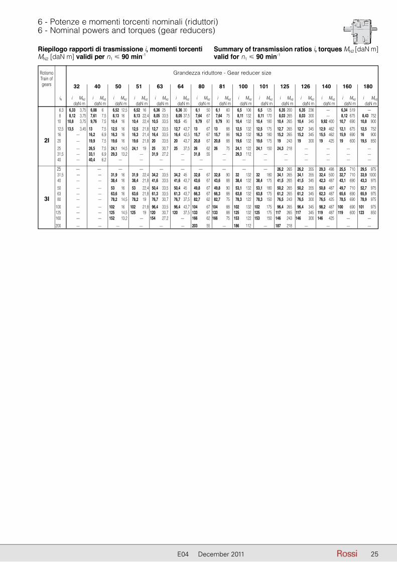
6 - Potenze e momenti torcenti nominali (riduttori)6 - Nominal powers and torques (gear reducers)
Riepilogo rapporti di trasmissione i, momenti torcenti MN2 [daN m] validi per n1 � 90 min-1
Summary of transmission ratios i, torques MN2 [daN m] valid for n1 � 90 min-1
Grandezza riduttore - Gear reducer size
6,3 6,33 3,75 6,08 6 6,52 12,5 6,52 16 6,36 25 6,36 30 6,1 50 6,1 60 6,5 106 6,5 125 6,35 200 6,35 236 — 6,34 519 — 8 8,12 3,75 7,61 7,5 8,13 16 8,13 22,4 8,05 33,5 8,05 37,5 7,64 67 7,64 75 8,11 132 8,11 170 8,03 265 8,03 300 — 8,12 675 8,43 752 10 10,8 3,75 9,76 7,5 10,4 16 10,4 22,4 10,5 33,5 10,5 45 9,79 67 9,79 90 10,4 132 10,4 180 10,4 265 10,4 345 9,92 400 10,7 690 10,8 900
12,5 13,5 3,45 13 7,5 12,5 16 12,5 21,8 12,7 33,5 12,7 43,7 13 67 13 88 12,5 132 12,5 175 12,7 265 12,7 345 12,9 462 12,1 675 12,5 752 16 — 16,2 6,9 16,3 16 16,3 21,4 16,4 33,5 16,4 42,5 15,7 67 15,7 86 16,3 132 16,3 180 15,2 265 15,2 345 15,5 462 15,9 690 16 900 2I 20 — 19,9 7,5 19,6 16 19,6 21,8 20 33,5 20 43,7 20,8 67 20,8 88 19,6 132 19,6 175 19 243 19 300 19 425 19 600 19,5 850
25 — 26,5 7,5 24,1 14,5 24,1 19 25 30,7 25 37,5 26 62 26 75 24,1 122 24,1 150 24,3 218 — — — — 31,5 — 33,1 6,9 29,3 13,2 — 31,9 27,2 — 31,8 55 — 29,3 112 — — — — — — 40 — 40,4 6,2 — — — — — — — — — — — — —
25 — — — — — — — — — — 26,2 265 26,2 355 29,3 498 25,5 710 29,5 975 31,5 — — 31,9 16 31,9 22,4 34,2 33,5 34,2 45 32,8 67 32,8 90 32 132 32 180 34,1 265 34,1 355 32,4 500 32,7 710 33,9 1000 40 — — 38,4 16 38,4 21,8 41,6 33,5 41,6 43,7 43,6 67 43,6 88 38,4 132 38,4 175 41,5 265 41,5 345 42,3 487 43,1 690 43,3 975
50 — — 53 16 53 22,4 50,4 33,5 50,4 45 49,8 67 49,8 90 53,1 132 53,1 180 50,2 265 50,2 355 50,8 487 49,7 710 52,7 975 63 — — 63,6 16 63,6 21,8 61,3 33,5 61,3 43,7 66,3 67 66,3 88 63,8 132 63,8 175 61,2 265 61,2 345 62,3 487 65,6 690 65,9 975 3I 80 — — 78,2 14,5 78,2 19 76,7 30,7 76,7 37,5 82,7 62 82,7 75 78,3 122 78,3 150 76,5 243 76,5 300 76,5 425 78,5 690 78,9 975
100 — — 102 16 102 21,8 96,4 33,5 96,4 43,7 104 67 104 88 102 132 102 175 96,4 265 96,4 345 98,2 487 100 690 101 975 125 — — 125 14,5 125 19 120 30,7 120 37,5 133 67 133 88 125 132 125 175 117 265 117 345 119 487 119 600 123 850 160 — — 152 13,2 — 154 27,2 — 166 62 166 75 153 122 153 150 146 243 146 300 146 425 — —
200 — — — — — — 203 55 — 186 112 — 187 218 — — — —
32 40 50 51 63 64 80 81 100 101 125 126 140 160 180
iN i MN2 i MN2 i MN2 i MN2 i MN2 i MN2 i MN2 i MN2 i MN2 i MN2 i MN2 i MN2 i MN2 i MN2 i MN2
daN m daN m daN m daN m daN m daN m daN m daN m daN m daN m daN m daN m daN m daN m daN m
RotismoTrain ofgears
25E04 December 2011

26 E04 December 2011
7 - Esecuzioni, dimensioni, forme costruttive e quantità di lubrificante
7 - Designs, dimensions, mounting positions and lubricant quantities
Forme costruttive e quantità di grasso [kg]
Salvo diversa indicazione i riduttori vengono forniti nelle forme costruttive normali B3 o B5 le quali, in quanto normali, non vanno indicate nella designazione.
Unless otherwise stated, gear reducers are supplied in mounting positions B3 or B5 which, being standard, are omitted from the designation.
Mounting positions and grease quantities [kg] Grandezza B3, B6 V5, V6 Size B7, B8
32 0,14 0,25 40 0,26 0,47
B5 V1, V3
32 0,10 0,18 40 0,19 0,35
B3 B6 B7 B8 V5 V6
B5 V1 V3
Esecuzione normaleForma costruttiva B3, B6, B7, B8, V5, V6
Standard design Mounting position B3, B6, B7, B8, V5, V6
Esecuzione normaleForma costruttiva B5, V1, V3
Standard design Mounting position B5, V1, V3
FC1A
Esec
uzio
ne -
Des
ign
PC1A
FC1A
1) Rispettivamente quote battuta estremità d’albero e piano flangia.2) Flangia entrata quadrata � 105: in caso di necessità interpellarci.
1) Dimensions of shaft end shoulder and flange surface respectively.2) Square input flange � 105: consult us if need be.
Grandezza A B C c D E d e Y1 F H K L M N P Q S T U V Z Massa Size Ø Ø h11 Ø Ø Ø Ø Mass h6 kg
32 115 53 20 103-931) 16 30 11 20 153 9,5 75 9,5 10 115 95 140 3,0 10 139 77 482) 73 4 40 132 63 19 122-931) 19 40 11 23 185 9,5 90 9,5 12 130 110 160 3,5 10 156 92 562) 87 7
PC1A
R 2I 32, 40

2727E04 December 2011
7 - Esecuzioni, dimensioni, forme costruttive e quantità di lubrificante
7 - Designs, dimensions, mounting positions and lubricant quantities
Forme costruttive e quantità di olio [l]
Salvo diversa indicazione i riduttori vengono forniti nella forma costruttiva normale B3 la quale, in quanto normale, non va indicata nella designazione.
Unless otherwise stated, gear reducers are supplied in mounting positions B3 which, being standard, is omitted from the designation.
Mounting positions and oil quantities [l] Grandezza B3 B6, B7 B8, V6 V5 Size
50, 51 0,8 1,1 1,1 1,4 63, 64 1,6 2,2 2,2 2,8 80, 81 3,1 4,3 4,3 5,5
100, 101 5,6 7,1 8,0 10,0 125, 126 10,2 13,0 14,6 18,3 140, 000 11,6 14,8 16,6 21,0
160, 000 19,6 25,0 28,0 35,0 180, 000 23,0 29,0 32,0 40,0
B3 B6 B7 B8 V5 V6
1) Per asse veloce la quota H è -15 mm, H0 +15 mm.2) Per asse veloce la quota H è -8 mm, H0 +8 mm.3) Per asse veloce la quota H è -29 mm, H0 +29 mm.4) Per R 3I la quota c è -4 mm (grand. 125 ... 140), -6 mm (grand. 160 e 180).
1) For high speed shaft H dimension is -15 mm, H0 +15 mm.2) For high speed shaft H dimension is -8 mm, H0 +8 mm.3) For high speed shaft H dimension is -29 mm, H0 +29 mm.4) For R 3I c dimension is -4 mm (sizes 125 ... 140), -6 mm (sizes 160 and 180).
Grand. A B C c D E d Y1 d Y1 d Y1 d Y1 F G1 H H0 K L L1 M N P P1 R S T U U1 W1 Massa Size Ø Ø Ø Ø Ø Ø h11 h11 Ø Ø Ø Ø Ø Mass R2I R3I h6 kg B1 e e e e Q+2
0
iN � 12,5 iN � 16 iN � 80 iN � 100
50 124 76 30,5 1380) 24 50 14 234 14 234 11 227 11 227 9,5 16 1060) 710) 11,5 17,5 12 130 110 160 140 13,5 10 148 110 100 177 12 51 52 28 42 30 226 30 226 23 219 23 219 3,5
63 153 96 36,5 1680) 32 58 19 285 16 275 14 275 14 275 11,5 19 1320) 850) 14,0 20,5 14 165 130 200 160 16,0 12 182 136 124 217 20 64 66 38 40 30 30 30 3,5
80 192 123 43,0 2080) 38 80 24 360 19 350 19 350 16 340 14,5 22 1600) 1060) 16,0 24,5 17 215 180 250 200 19,0 14 226 171 157 266 35 81 87 48 50 40 40 30 4
100 240 160 51,5 2530) 48 82 28 422 24 412 24 412 19 402 14,5 27 1950) 1320) 18,0 28,5 20 265 230 300 250 22,5 16 280 214 198 327 62 101 119 55 60 50 50 40 4
125 297 200 59,0 3114) 60 105 32 526 32 526 28 502 24 492 18,5 30 2360) 1600) 22,0 35,5 25 300 250 350 300 26,5 19 345 264 245 396 110 126 151 70 80 80 60 50 5
140 297 218 59,0 3294) 80 130 32 569 32 569 28 545 24 535 18,5 30 2501) 1601) 22,0 35,5 25 300 250 350 300 26,5 19 345 282 263 410 123 169 80 80 60 50 5
160 373 250 68,5 3854) 90 130 42 659 42 659 32 623 32 623 22,5 34 2952) 2002) 27,0 42,5 30 400 350 450 400 31,5 22 430 326 304 495 195 191 110 110 80 80 5
180 373 275 68,5 4104) 100 165 42 719 42 719 32 683 32 683 22,5 34 3153) 2003) 27,0 42,5 30 400 350 450 400 31,5 22 430 351 329 515 260 216 110 110 80 80 5
Esecuzione normaleForma costruttiva B3, B6, B7, B8, V5, V6
Standard design Mounting position B3, B6, B7, B8, V5, V6
UC2A
R 2I, 3I 50 ... 180

28 E04 December 2011
8 - Programma di fabbricazione (motoriduttori)8 - Selection tables (gearmotors)
P1 n2 M2 fs Riduttore - Motore i kW min-1 daN m Gear reducer - Motor
1) 2)
1) Potenze per servizio continuo S1; per servizi S2 ... S10 è possibile incrementarle (cap. 2b); proporzionalmente M2 aumenta e fs diminuisce.
2) Per la designazione completa per l’ordinazione ved. cap. 3.
0,09 6,91 11,9 1,12 MR 3I 50 - 63 A 6 130 8,4 9,8 1,5 MR 3I 50 - 63 A 6 107 8,4 9,8 1,9 MR 3I 51 - 63 A 6 107 9,7 8,5 0,8 MR 3I 40 - 63 A 6 92,8 10,3 8 2 MR 3I 50 - 63 A 6 87,3 10,3 8 2,8 MR 3I 51 - 63 A 6 87,3 12,1 6,8 1,12 MR 3I 40 - 63 A 6 74,4 12,1 6,8 1,32 MR 3I 41 - 63 A 6 74,4 12,6 6,5 2,5 MR 3I 50 - 63 A 6 71,4 13,7 6 1,25 MR 3I 40 - 63 A 6 65,9 13,7 6 1,6 MR 3I 41 - 63 A 6 65,9 13,8 6 2,65 MR 3I 50 - 63 A 6 65 15,1 5,5 3 MR 3I 50 - 63 A 6 59,5 16,1 5,1 1,5 MR 3I 40 - 63 A 6 55,9 16,1 5,1 1,9 MR 3I 41 - 63 A 6 55,9 17,5 4,71 3,35 MR 3I 50 - 63 A 6 51,4 17,5 4,7 1,6 MR 3I 40 - 63 A 6 51,3 17,5 4,7 2 MR 3I 41 - 63 A 6 51,3 18,9 4,35 0,85 MR 3I 32 - 63 A 6 47,5 20,1 4,1 1,8 MR 3I 40 - 63 A 6 44,7 20,1 4,1 2,24 MR 3I 41 - 63 A 6 44,7 20,9 3,94 4 MR 3I 50 - 63 A 6 43 21,4 3,86 0,95 MR 3I 32 - 63 A 6 42,1 22,7 3,63 2,12 MR 3I 40 - 63 A 6 39,6 22,7 3,63 2,65 MR 3I 41 - 63 A 6 39,6 25,2 3,27 1,12 MR 3I 32 - 63 A 6 35,7 26,8 3,08 2,5 MR 3I 40 - 63 A 6 33,6 28,1 2,94 1,25 MR 3I 32 - 63 A 6 32,1 29,2 2,82 2,65 MR 3I 40 - 63 A 6 30,8 32,1 2,57 1,4 MR 3I 32 - 63 A 6 28,1 34,3 2,41 3 MR 3I 40 - 63 A 6 26,2 36,2 2,28 1,6 MR 3I 32 - 63 A 6 24,9 40,7 2,07 2,8 MR 2I 40 - 63 A 6 22,1 42,6 1,94 1,9 MR 3I 32 - 63 A 6 21,1 47,5 1,74 2,12 MR 3I 32 - 63 A 6 18,9 54,7 1,51 2,24 MR 3I 32 - 63 A 6 16,5 66,8 1,26 2,5 MR 2I 32 - 63 A 6 13,5 83,4 1,01 3,35 MR 2I 32 - 63 A 6 10,8 94,1 0,9 3,75 MR 2I 32 - 63 A 6 9,57
0,12 6,91 15,9 0,85 MR 3I 50 - 63 B 6 130 8,4 13,1 1,12 MR 3I 50 - 63 B 6 107 8,4 13,1 1,4 MR 3I 51 - 63 B 6 107 10,3 10,7 1,5 MR 3I 50 - 63 B 6 87,3 10,3 10,7 2 MR 3I 51 - 63 B 6 87,3 10,7 10,2 1,32 MR 3I 50 - 63 A 4 130 12,1 9,1 0,8 MR 3I 40 - 63 B 6 74,4 12,1 9,1 1 MR 3I 41 - 63 B 6 74,4 13,1 8,4 1,7 MR 3I 50 - 63 A 4 107 13,1 8,4 2,24 MR 3I 51 - 63 A 4 107 13,7 8,1 0,95 MR 3I 40 - 63 B 6 65,9 13,7 8,1 1,18 MR 3I 41 - 63 B 6 65,9 13,8 7,9 2 MR 3I 50 - 63 B 6 65 13,8 7,9 2,8 MR 3I 51 - 63 B 6 65 15,1 7,3 0,95 MR 3I 40 - 63 A 4 92,8 16 6,9 2,36 MR 3I 50 - 63 A 4 87,3 16 6,9 3,15 MR 3I 51 - 63 A 4 87,3 16,1 6,8 1,12 MR 3I 40 - 63 B 6 55,9 16,1 6,8 1,4 MR 3I 41 - 63 B 6 55,9 17,5 6,3 2,5 MR 3I 50 - 63 B 6 51,4 18,8 5,8 1,32 MR 3I 40 - 63 A 4 74,4 18,8 5,8 1,6 MR 3I 41 - 63 A 4 74,4 19,6 5,6 2,8 MR 3I 50 - 63 A 4 71,4 20,1 5,5 1,4 MR 3I 40 - 63 B 6 44,7 20,1 5,5 1,7 MR 3I 41 - 63 B 6 44,7 21,2 5,2 1,4 MR 3I 40 - 63 A 4 65,9
P1 n2 M2 fs Riduttore - Motore i kW min-1 daN m Gear reducer - Motor
1) 2)
1) Powers valid for continuous duty S1; increase possible for S2 ... S10 (ch. 2b) in which case M2 increases and fs decreases proportionately.
2) For complete designation when ordering, see ch. 3.
0,12 21,2 5,2 1,8 MR 3I 41 - 63 A 4 65,9 21,5 5,1 3,15 MR 3I 50 - 63 A 4 65 22,7 4,84 2 MR 3I 41 - 63 B 6 39,6 23,5 4,67 3,35 MR 3I 50 - 63 A 4 59,5 25 4,4 1,7 MR 3I 40 - 63 A 4 55,9 25 4,4 2,12 MR 3I 41 - 63 A 4 55,9 25,2 4,37 0,85 MR 3I 32 - 63 B 6 35,7 27,2 4,04 4 MR 3I 50 - 63 A 4 51,4 27,3 4,03 1,9 MR 3I 40 - 63 A 4 51,3 27,3 4,03 2,24 MR 3I 41 - 63 A 4 51,3 29,5 3,73 1 MR 3I 32 - 63 A 4 47,5 31,3 3,51 2,12 MR 3I 40 - 63 A 4 44,7 31,3 3,51 2,65 MR 3I 41 - 63 A 4 44,7 33,3 3,31 1,12 MR 3I 32 - 63 A 4 42,1 35,3 3,11 2,36 MR 3I 40 - 63 A 4 39,6 35,3 3,11 3 MR 3I 41 - 63 A 4 39,6 36,2 3,04 1,18 MR 3I 32 - 63 B 6 24,9 39,2 2,81 1,32 MR 3I 32 - 63 A 4 35,7 40,7 2,76 2,12 MR 2I 40 - 63 B 6 22,1 41,6 2,64 2,8 MR 3I 40 - 63 A 4 33,6 43,7 2,52 1,4 MR 3I 32 - 63 A 4 32,1 45,5 2,42 3 MR 3I 40 - 63 A 4 30,8 49,7 2,26 3 MR 2I 40 - 63 B 6 18,1 49,9 2,21 1,6 MR 3I 32 - 63 A 4 28,1 53,4 2,06 3,35 MR 3I 40 - 63 A 4 26,2 55,5 2,02 3,35 MR 2I 40 - 63 B 6 16,2 56,3 1,95 1,8 MR 3I 32 - 63 A 4 24,9 63,3 1,77 3,35 MR 2I 40 - 63 A 4 22,1 66,3 1,66 2,12 MR 3I 32 - 63 A 4 21,1 66,8 1,68 1,9 MR 2I 32 - 63 B 6 13,5 73,9 1,49 2,36 MR 3I 32 - 63 A 4 18,9 83,4 1,35 2,5 MR 2I 32 - 63 B 6 10,8 85 1,29 2,5 MR 3I 32 - 63 A 4 16,5 94,1 1,19 2,8 MR 2I 32 - 63 B 6 9,57 104 1,08 3 MR 2I 32 - 63 A 4 13,5 130 0,87 4 MR 2I 32 - 63 A 4 10,8 146 0,77 4,5 MR 2I 32 - 63 A 4 9,57 172 0,65 5,3 MR 2I 32 - 63 A 4 8,12 192 0,58 5,6 MR 2I 32 - 63 A 4 7,29 221 0,51 6,7 MR 2I 32 - 63 A 4 6,33 277 0,41 6,7 MR 2I 32 - 63 A 4 5,06
0,18 6,33 26,1 1,06 MR 3I 63 - 71 A 6 142 8,09 20,4 1,5 MR 3I 63 - 71 A 6 111 8,09 20,4 1,8 MR 3I 64 - 71 A 6 111 10,1 16,3 2 MR 3I 63 - 71 A 6 89 10,1 16,3 2,65 MR 3I 64 - 71 A 6 89 10,7 15,4 0,85 MR 3I 50 - 63 B 4 130 11,6 14,2 1 MR 3I 50 - 71 A 6 77,7 11,6 14,2 1,32 MR 3I 51 - 71 A 6 77,7 12,1 13,7 2,5 MR 3I 63 - 71 A 6 74,5 13,1 12,6 1,12 MR 3I 50 - 63 B 4 107 13,1 12,6 1,5 MR 3I 51 - 63 B 4 107 14,2 11,6 1,4 MR 3I 50 - 71 A 6 63,2 14,2 11,6 1,9 MR 3I 51 - 71 A 6 63,2 14,7 11,2 3 MR 3I 63 - 71 A 6 61,3 16 10,3 1,6 MR 3I 50 - 63 B 4 87,3 16 10,3 2,12 MR 3I 51 - 63 B 4 87,3 16,7 9,9 0,95 MR 3I 41 - 71 A 6 53,9 17,4 9,5 1,7 MR 3I 50 - 71 A 6 51,7 17,4 9,5 2,24 MR 3I 51 - 71 A 6 51,7 18,8 8,8 0,85 MR 3I 40 - 63 B 4 74,4 18,8 8,8 1,06 MR 3I 41 - 63 B 4 74,4 19,6 8,4 1,9 MR 3I 50 - 63 B 4 71,4 19,6 8,4 2,65 MR 3I 51 - 63 B 4 71,4 21,2 7,8 0,95 MR 3I 40 - 63 B 4 65,9
28

2929E04 December 2011
8 - Programma di fabbricazione (motoriduttori)8 - Selection tables (gearmotors)
P1 n2 M2 fs Riduttore - Motore i kW min-1 daN m Gear reducer - Motor
1) 2)
1) Potenze per servizio continuo S1; per servizi S2 ... S10 è possibile incrementarle (cap. 2b); proporzionalmente M2 aumenta e fs diminuisce.
2) Per la designazione completa per l’ordinazione ved. cap. 3.
0,18 21,2 7,8 1,25 MR 3I 41 - 63 B 4 65,9 21,5 7,7 2,12 MR 3I 50 - 63 B 4 65 21,5 7,7 3 MR 3I 51 - 63 B 4 65 23,5 7 2,24 MR 3I 50 - 63 B 4 59,5 25 6,6 1,12 MR 3I 40 - 63 B 4 55,9 25 6,6 1,4 MR 3I 41 - 63 B 4 55,9 27,2 6,1 2,65 MR 3I 50 - 63 B 4 51,4 27,3 6 1,25 MR 3I 40 - 63 B 4 51,3 27,3 6 1,5 MR 3I 41 - 63 B 4 51,3 31,3 5,3 1,4 MR 3I 40 - 63 B 4 44,7 31,3 5,3 1,7 MR 3I 41 - 63 B 4 44,7 32,5 5,1 3,15 MR 3I 50 - 63 B 4 43 35,3 4,67 1,6 MR 3I 40 - 63 B 4 39,6 35,3 4,67 2 MR 3I 41 - 63 B 4 39,6 35,7 4,62 3,35 MR 3I 50 - 63 B 4 39,2 39,1 4,22 3,75 MR 3I 50 - 63 B 4 35,8 39,2 4,21 0,85 MR 3I 32 - 63 B 4 35,7 41,6 3,96 1,9 MR 3I 40 - 63 B 4 33,6 41,6 3,96 2,36 MR 3I 41 - 63 B 4 33,6 43,7 3,78 0,9 MR 3I 32 - 63 B 4 32,1 45,5 3,63 2 MR 3I 40 - 63 B 4 30,8 45,5 3,63 2,5 MR 3I 41 - 63 B 4 30,8 49,9 3,31 1,06 MR 3I 32 - 63 B 4 28,1 53,4 3,09 2,24 MR 3I 40 - 63 B 4 26,2 53,4 3,09 2,65 MR 3I 41 - 63 B 4 26,2 55,6 3,03 1,9 MR 2I 40 - 71 A 6 16,2 56,3 2,93 1,18 MR 3I 32 - 63 B 4 24,9 63,3 2,66 2,12 MR 2I 40 - 63 B 4 22,1 66,3 2,49 1,4 MR 3I 32 - 63 B 4 21,1 67,7 2,49 2,65 MR 2I 40 - 71 A 6 13,3 73,9 2,23 1,6 MR 3I 32 - 63 B 4 18,9 77,3 2,18 3 MR 2I 40 - 63 B 4 18,1 85 1,94 1,7 MR 3I 32 - 63 B 4 16,5 86,3 1,95 3,35 MR 2I 40 - 63 B 4 16,2 96,6 1,74 4 MR 2I 40 - 63 B 4 14,5 104 1,62 1,9 MR 2I 32 - 63 B 4 13,5 109 1,54 4,5 MR 2I 40 - 63 B 4 12,8 130 1,3 2,65 MR 2I 32 - 63 B 4 10,8 146 1,15 3 MR 2I 32 - 63 B 4 9,57 172 0,98 3,35 MR 2I 32 - 63 B 4 8,12 192 0,88 3,75 MR 2I 32 - 63 B 4 7,29 221 0,76 4,5 MR 2I 32 - 63 B 4 6,33 277 0,61 4,5 MR 2I 32 - 63 B 4 5,06
0,25 8,09 28,3 1,06 MR 3I 63 - 71 B 6 111 8,09 28,3 1,32 MR 3I 64 - 71 B 6 111 9,85 23,3 1,18 MR 3I 63 - 71 A 4 142 10,1 22,7 1,5 MR 3I 63 - 71 B 6 89 10,1 22,7 1,9 MR 3I 64 - 71 B 6 89 11,6 19,8 0,95 MR 3I 51 - 71 B 6 77,7 12,1 19 2,36 MR 3I 64 - 71 B 6 74,5 12,6 18,2 1,7 MR 3I 63 - 71 A 4 111 12,6 18,2 2 MR 3I 64 - 71 A 4 111 13,1 17,6 0,85 MR 3I 50 - 63 C 4 107 13,1 17,6 1,06 MR 3I 51 - 63 C 4 107 14,2 16,1 1 MR 3I 50 - 71 B 6 63,2 14,2 16,1 1,32 MR 3I 51 - 71 B 6 63,2 14,7 15,6 2,12 MR 3I 63 - 71 B 6 61,3 14,8 15,5 0,85 MR 3I 50 - 71 A 4 94,4 15,7 14,6 2,24 MR 3I 63 - 71 A 4 89 15,7 14,6 3 MR 3I 64 - 71 A 4 89 16 14,3 1,12 MR 3I 50 - 63 C 4 87,3 16 14,3 1,5 MR 3I 51 - 63 C 4 87,3 17,4 13,2 1,7 MR 3I 51 - 71 B 6 51,7 18 12,7 1,12 MR 3I 50 - 71 A 4 77,7 18 12,7 1,5 MR 3I 51 - 71 A 4 77,7
P1 n2 M2 fs Riduttore - Motore i kW min-1 daN m Gear reducer - Motor
1) 2)
1) Powers valid for continuous duty S1; increase possible for S2 ... S10 (ch. 2b) in which case M2 increases and fs decreases proportionately.
2) For complete designation when ordering, see ch. 3.
0,25 18,8 12,2 2,8 MR 3I 63 - 71 A 4 74,5 19,4 11,8 2,8 MR 3I 63 - 71 B 6 46,3 19,6 11,7 1,4 MR 3I 50 - 63 C 4 71,4 19,6 11,7 1,9 MR 3I 51 - 63 C 4 71,4 21,2 10,8 0,9 MR 3I 41 - 63 C 4 65,9 21,5 10,6 1,5 MR 3I 50 - 63 C 4 65 21,5 10,6 2,12 MR 3I 51 - 63 C 4 65 22,1 10,4 1,5 MR 3I 50 - 71 A 4 63,2 22,1 10,4 2,12 MR 3I 51 - 71 A 4 63,2 22,8 10 3,35 MR 3I 63 - 71 A 4 61,3 23,5 9,7 1,6 MR 3I 50 - 63 C 4 59,5 23,5 9,7 2,36 MR 3I 51 - 63 C 4 59,5 24,5 9,4 1,6 MR 3I 50 - 71 A 4 57,1 24,5 9,4 2,24 MR 3I 51 - 71 A 4 57,1 25 9,2 0,8 MR 3I 40 - 63 C 4 55,9 25 9,2 1,06 MR 3I 41 - 63 C 4 55,9 25,3 9,1 3,75 MR 3I 63 - 71 A 4 55,4 26 8,8 0,85 MR 3I 40 - 71 A 4 53,9 26 8,8 1,06 MR 3I 41 - 71 A 4 53,9 27,1 8,5 1,9 MR 3I 50 - 71 A 4 51,7 27,1 8,5 2,5 MR 3I 51 - 71 A 4 51,7 27,2 8,4 1,9 MR 3I 50 - 63 C 4 51,4 27,2 8,4 2,65 MR 3I 51 - 63 C 4 51,4 27,3 8,4 0,9 MR 3I 40 - 63 C 4 51,3 27,3 8,4 1,06 MR 3I 41 - 63 C 4 51,3 29,3 7,8 0,95 MR 3I 40 - 71 A 4 47,7 29,3 7,8 1,18 MR 3I 41 - 71 A 4 47,7 29,7 7,7 2 MR 3I 50 - 71 A 4 47,1 29,7 7,7 2,8 MR 3I 51 - 71 A 4 47,1 31,3 7,3 1 MR 3I 40 - 63 C 4 44,7 31,3 7,3 1,25 MR 3I 41 - 63 C 4 44,7 32,5 7,1 2,24 MR 3I 50 - 71 A 4 43,1 32,5 7,1 3,15 MR 3I 51 - 71 A 4 43,1 32,5 7 2,24 MR 3I 50 - 63 C 4 43 34,6 6,6 1,12 MR 3I 40 - 71 A 4 40,5 34,6 6,6 1,4 MR 3I 41 - 71 A 4 40,5 35,3 6,5 1,12 MR 3I 40 - 63 C 4 39,6 35,3 6,5 1,4 MR 3I 41 - 63 C 4 39,6 35,7 6,4 2,5 MR 3I 50 - 63 C 4 39,2 37,6 6,1 2,65 MR 3I 50 - 71 A 4 37,2 37,7 6,1 1,25 MR 3I 40 - 71 A 4 37,1 37,7 6,1 1,5 MR 3I 41 - 71 A 4 37,1 39,1 5,9 2,65 MR 3I 50 - 63 C 4 35,8 40,4 5,8 2,24 MR 2I 50 - 71 B 6 22,3 41,6 5,5 1,32 MR 3I 40 - 63 C 4 33,6 41,6 5,5 1,7 MR 3I 41 - 63 C 4 33,6 43,2 5,3 1,32 MR 3I 40 - 71 A 4 32,4 43,2 5,3 1,7 MR 3I 41 - 71 A 4 32,4 44,9 5,1 3 MR 3I 50 - 71 A 4 31,2 45,2 5,1 3,15 MR 3I 50 - 63 C 4 31 45,5 5 1,5 MR 3I 40 - 63 C 4 30,8 45,5 5 1,8 MR 3I 41 - 63 C 4 30,8 48,8 4,7 1,5 MR 3I 40 - 71 A 4 28,7 48,8 4,7 1,9 MR 3I 41 - 71 A 4 28,7 49,3 4,65 3,35 MR 3I 50 - 71 A 4 28,4 49,9 4,6 0,8 MR 3I 32 - 63 C 4 28,1 53,4 4,3 1,6 MR 3I 40 - 63 C 4 26,2 53,4 4,3 1,9 MR 3I 41 - 63 C 4 26,2 53,9 4,25 3,55 MR 3I 50 - 71 A 4 26 55,6 4,21 1,4 MR 2I 40 - 71 B 6 16,2 56,3 4,07 0,9 MR 3I 32 - 63 C 4 24,9 57,5 3,99 1,8 MR 3I 40 - 71 A 4 24,4 57,5 3,99 2,24 MR 3I 41 - 71 A 4 24,4 62,4 3,67 4,25 MR 3I 50 - 71 A 4 22,4 62,8 3,65 2 MR 3I 40 - 71 A 4 22,3 62,8 3,65 2,5 MR 3I 41 - 71 A 4 22,3 62,9 3,72 3,35 MR 2I 50 - 71 A 4 22,3 63,3 3,69 1,6 MR 2I 40 - 63 C 4 22,1 66,3 3,46 1,06 MR 3I 32 - 63 C 4 21,1 67,7 3,46 1,9 MR 2I 40 - 71 B 6 13,3
29E04 December 2011

30 E04 December 2011
8 - Programma di fabbricazione (motoriduttori)8 - Selection tables (gearmotors)
P1 n2 M2 fs Riduttore - Motore i kW min-1 daN m Gear reducer - Motor
1) 2)
1) Potenze per servizio continuo S1; per servizi S2 ... S10 è possibile incrementarle (cap. 2b); proporzionalmente M2 aumenta e fs diminuisce.
2) Per la designazione completa per l’ordinazione ved. cap. 3.
0,25 67,7 3,46 2,12 MR 2I 41 - 71 B 6 13,3 73,7 3,11 2,12 MR 3I 40 - 71 A 4 19 73,7 3,11 2,65 MR 3I 41 - 71 A 4 19 73,9 3,1 1,18 MR 3I 32 - 63 C 4 18,9 76,6 3,06 2,24 MR 2I 40 - 71 B 6 11,8 76,6 3,06 2,65 MR 2I 41 - 71 B 6 11,8 77,3 3,02 2,12 MR 2I 40 - 63 C 4 18,1 85 2,7 1,18 MR 3I 32 - 63 C 4 16,5 86,3 2,71 2,5 MR 2I 40 - 63 C 4 16,2 86,3 2,71 3 MR 2I 41 - 63 C 4 16,2 86,4 2,71 2,12 MR 2I 40 - 71 A 4 16,2 92,2 2,49 2,12 MR 3I 40 - 71 A 4 15,2 96,6 2,42 2,8 MR 2I 40 - 63 C 4 14,5 104 2,25 1,4 MR 2I 32 - 63 C 4 13,5 105 2,22 2,8 MR 2I 40 - 71 A 4 13,3 109 2,14 3,15 MR 2I 40 - 63 C 4 12,8 119 1,96 3,35 MR 2I 40 - 71 A 4 11,8 128 1,82 3,75 MR 2I 40 - 63 C 4 10,9 130 1,8 1,9 MR 2I 32 - 63 C 4 10,8 133 1,77 3,75 MR 2I 40 - 71 A 4 10,6 146 1,6 2,12 MR 2I 32 - 63 C 4 9,57 149 1,57 4,25 MR 2I 40 - 71 A 4 9,41 172 1,36 2,5 MR 2I 32 - 63 C 4 8,12 175 1,33 5 MR 2I 40 - 71 A 4 7,98 191 1,22 5,6 MR 2I 40 - 71 A 4 7,32 192 1,22 2,8 MR 2I 32 - 63 C 4 7,29 221 1,06 3,15 MR 2I 32 - 63 C 4 6,33 277 0,85 3,35 MR 2I 32 - 63 C 4 5,06 345 0,68 4,75 MR 2I 32 - 63 B 2 8,12 384 0,61 5,3 MR 2I 32 - 63 B 2 7,29 442 0,53 6 MR 2I 32 - 63 B 2 6,33 554 0,42 6,3 MR 2I 32 - 63 B 2 5,06
0,37 5,84 58 0,95 MR 3I 80 - 80 A 6 154 7,13 47,6 1,32 MR 3I 80 - 80 A 6 126 7,13 47,6 1,6 MR 3I 81 - 80 A 6 126 8,09 41,9 0,9 MR 3I 64 - 71 C 6 111 8,9 38,1 1,8 MR 3I 80 - 80 A 6 101 8,9 38,1 2,24 MR 3I 81 - 80 A 6 101 9,85 34,4 0,8 MR 3I 63 - 71 B 4 142 10,1 33,6 1 MR 3I 63 - 71 C 6 89 10,1 33,6 1,32 MR 3I 64 - 71 C 6 89 10,6 31,9 2,12 MR 3I 80 - 80 A 6 84,6 10,6 31,9 2,8 MR 3I 81 - 80 A 6 84,6 12,1 28,1 1,18 MR 3I 63 - 71 C 6 74,5 12,1 28,1 1,6 MR 3I 64 - 71 C 6 74,5 12,6 27 1,12 MR 3I 63 - 71 B 4 111 12,6 27 1,4 MR 3I 64 - 71 B 4 111 13,6 25 2,65 MR 3I 80 - 80 A 6 66,3 14,2 23,8 0,9 MR 3I 51 - 71 C 6 63,2 14,7 23,1 1,4 MR 3I 63 - 71 C 6 61,3 14,7 23,1 1,9 MR 3I 64 - 71 C 6 61,3 15,3 22,1 3 MR 3I 80 - 80 A 6 58,7 15,7 21,6 1,6 MR 3I 63 - 71 B 4 89 15,7 21,6 2 MR 3I 64 - 71 B 4 89 16,1 21,1 1 MR 3I 51 - 80 A 6 55,9 17,8 19,1 0,85 MR 3I 50 - 80 A 6 50,6 17,8 19,1 1,12 MR 3I 51 - 80 A 6 50,6 18 18,8 0,8 MR 3I 50 - 71 B 4 77,7 18 18,8 1 MR 3I 51 - 71 B 4 77,7 18,8 18,1 1,9 MR 3I 63 - 71 B 4 74,5 18,8 18,1 2,36 MR 3I 64 - 71 B 4 74,5 19,4 17,5 2,36 MR 3I 64 - 71 C 6 46,3 20,4 16,7 2 MR 3I 63 - 80 A 6 44,2 20,9 16,2 1 MR 3I 50 - 71 C 6 43,1 20,9 16,2 1,4 MR 3I 51 - 71 C 6 43,1 22,1 15,3 1,06 MR 3I 50 - 71 B 4 63,2
P1 n2 M2 fs Riduttore - Motore i kW min-1 daN m Gear reducer - Motor
1) 2)
1) Powers valid for continuous duty S1; increase possible for S2 ... S10 (ch. 2b) in which case M2 increases and fs decreases proportionately.
2) For complete designation when ordering, see ch. 3.
0,37 22,1 15,3 1,4 MR 3I 51 - 71 B 4 63,2 22,8 14,9 2,24 MR 3I 63 - 71 B 4 61,3 22,8 14,9 3 MR 3I 64 - 71 B 4 61,3 24,5 13,8 1,12 MR 3I 50 - 71 B 4 57,1 24,5 13,8 1,5 MR 3I 51 - 71 B 4 57,1 25,3 13,4 2,5 MR 3I 63 - 71 B 4 55,4 26,1 13 1,7 MR 3I 51 - 80 A 6 34,5 27,1 12,5 1,25 MR 3I 50 - 71 B 4 51,7 27,1 12,5 1,7 MR 3I 51 - 71 B 4 51,7 27,8 12,2 2,8 MR 3I 63 - 71 B 4 50,4 29,3 11,6 0,8 MR 3I 41 - 71 B 4 47,7 29,7 11,4 1,4 MR 3I 50 - 71 B 4 47,1 29,7 11,4 1,9 MR 3I 51 - 71 B 4 47,1 30,2 11,2 2,8 MR 3I 63 - 71 B 4 46,3 31,3 10,8 0,85 MR 3I 41 - 71 C 6 28,7 32,5 10,4 1,5 MR 3I 50 - 71 B 4 43,1 32,5 10,4 2,12 MR 3I 51 - 71 B 4 43,1 33,7 10,1 3,15 MR 3I 63 - 71 B 4 41,6 34,6 9,8 0,95 MR 3I 41 - 71 B 4 40,5 34,7 9,8 1,6 MR 3I 50 - 71 C 6 26 34,7 9,8 2,24 MR 3I 51 - 71 C 6 26 37,3 9,1 3,55 MR 3I 63 - 71 B 4 37,6 37,6 9 1,8 MR 3I 50 - 71 B 4 37,2 37,6 9 2,5 MR 3I 51 - 71 B 4 37,2 37,7 9 0,85 MR 3I 40 - 71 B 4 37,1 37,7 9 1 MR 3I 41 - 71 B 4 37,1 40,4 8,4 1,12 MR 3I 41 - 71 C 6 22,3 40,4 8,6 1,5 MR 2I 50 - 71 C 6 22,3 43,2 7,9 0,9 MR 3I 40 - 71 B 4 32,4 43,2 7,9 1,12 MR 3I 41 - 71 B 4 32,4 44,9 7,6 2 MR 3I 50 - 71 B 4 31,2 44,9 7,6 2,8 MR 3I 51 - 71 B 4 31,2 48,8 7 1,06 MR 3I 40 - 71 B 4 28,7 48,8 7 1,32 MR 3I 41 - 71 B 4 28,7 49,3 6,9 2,24 MR 3I 50 - 71 B 4 28,4 49,3 6,9 3,15 MR 3I 51 - 71 B 4 28,4 53,9 6,3 2,5 MR 3I 50 - 71 B 4 26 57,5 5,9 1,18 MR 3I 40 - 71 B 4 24,4 57,5 5,9 1,5 MR 3I 41 - 71 B 4 24,4 62,4 5,4 2,8 MR 3I 50 - 71 B 4 22,4 62,8 5,4 1,32 MR 3I 40 - 71 B 4 22,3 62,8 5,4 1,7 MR 3I 41 - 71 B 4 22,3 62,9 5,5 2,24 MR 2I 50 - 71 B 4 22,3 67,7 5,1 1,25 MR 2I 40 - 71 C 6 13,3 67,7 5,1 1,4 MR 2I 41 - 71 C 6 13,3 69 4,92 3,15 MR 3I 50 - 71 B 4 20,3 73,7 4,61 1,5 MR 3I 40 - 71 B 4 19 73,7 4,61 1,7 MR 3I 41 - 71 B 4 19 76,5 4,53 3 MR 2I 50 - 71 B 4 18,3 76,6 4,52 1,5 MR 2I 40 - 71 C 6 11,8 76,6 4,52 1,8 MR 2I 41 - 71 C 6 11,8 85 3,99 0,8 MR 3I 32 - 71 B 4 16,5 85 4,07 3,55 MR 2I 50 - 71 B 4 16,5 85,2 4,07 1,7 MR 2I 40 - 71 C 6 10,6 85,2 4,07 2,12 MR 2I 41 - 71 C 6 10,6 86,4 4,01 1,4 MR 2I 40 - 71 B 4 16,2 92,2 3,68 1,5 MR 3I 40 - 71 B 4 15,2 93,9 3,69 4 MR 2I 50 - 71 B 4 14,9 102 3,41 4 MR 2I 50 - 71 B 4 13,8 104 3,33 0,95 MR 2I 32 - 71 B 4 13,5 105 3,29 1,9 MR 2I 40 - 71 B 4 13,3 105 3,29 2,12 MR 2I 41 - 71 B 4 13,3 112 3,09 4,75 MR 2I 50 - 71 B 4 12,5 119 2,91 2,24 MR 2I 40 - 71 B 4 11,8 119 2,91 2,65 MR 2I 41 - 71 B 4 11,8 130 2,67 1,25 MR 2I 32 - 71 B 4 10,8 133 2,61 2,5 MR 2I 40 - 71 B 4 10,6 146 2,37 1,4 MR 2I 32 - 71 B 4 9,57 149 2,33 2,8 MR 2I 40 - 71 B 4 9,41

3131E04 December 2011
8 - Programma di fabbricazione (motoriduttori)8 - Selection tables (gearmotors)
P1 n2 M2 fs Riduttore - Motore i kW min-1 daN m Gear reducer - Motor
1) 2)
1) Potenze per servizio continuo S1; per servizi S2 ... S10 è possibile incrementarle (cap. 2b); proporzionalmente M2 aumenta e fs diminuisce.
2) Per la designazione completa per l’ordinazione ved. cap. 3.* Forma costruttiva B5R (ved. tabella cap. 2b).
0,37 172 2,01 1,7 MR 2I 32 - 71 B 4 8,12 175 1,97 3,35 MR 2I 40 - 71 B 4 7,98 191 1,81 3,75 MR 2I 40 - 71 B 4 7,32 192 1,8 1,9 MR 2I 32 - 71 B 4 7,29 208 1,67 1,8 MR 2I 32 - 63 C 2 13,5 221 1,57 2,12 MR 2I 32 - 71 B 4 6,33 225 1,54 4,25 MR 2I 40 - 71 B 4 6,22 259 1,34 2,36 MR 2I 32 - 63 C 2 10,8 277 1,25 2,24 MR 2I 32 - 71 B 4 5,06 282 1,23 4,5 MR 2I 40 - 71 B 4 4,97 293 1,18 2,65 MR 2I 32 - 63 C 2 9,57 345 1 3,15 MR 2I 32 - 63 C 2 8,12 384 0,9 3,55 MR 2I 32 - 63 C 2 7,29 442 0,78 4 MR 2I 32 - 63 C 2 6,33 554 0,63 4,25 MR 2I 32 - 63 C 2 5,06
0,55 7,13 71 0,85 MR 3I 80 - 80 B 6 126 7,13 71 1,06 MR 3I 81 - 80 B 6 126 8,9 57 1,18 MR 3I 80 - 80 B 6 101 8,9 57 1,5 MR 3I 81 - 80 B 6 101 9,08 56 1 MR 3I 80 - 80 A 4 154 10,6 47,4 1,4 MR 3I 80 - 80 B 6 84,6 10,6 47,4 1,8 MR 3I 81 - 80 B 6 84,6 11,1 45,4 1,32 MR 3I 80 - 80 A 4 126 11,1 45,4 1,7 MR 3I 81 - 80 A 4 126 12,1 41,7 0,9 MR 3I 64 - 80 B 6 74,3 12,6 40,1 0,95 MR 3I 64 - 71 C 4 111 13,8 36,4 1,8 MR 3I 80 - 80 A 4 101 13,8 36,4 2,36 MR 3I 81 - 80 A 4 101 14,7 34,2 0,8 MR 3I 63 - 80 A 4 94,9 15,1 33,3 1 MR 3I 63 - 80 B 6 59,5 15,1 33,3 1,32 MR 3I 64 - 80 B 6 59,5 15,7 32,1 1,06 MR 3I 63 - 71 C 4 89 15,7 32,1 1,4 MR 3I 64 - 71 C 4 89 16,5 30,5 2,24 MR 3I 80 - 80 A 4 84,6 16,5 30,5 2,8 MR 3I 81 - 80 A 4 84,6 18,1 27,9 2,36 MR 3I 80 - 80 B 6 49,8 18,4 27,4 1,6 MR 3I 64 - 80 B 6 48,9 18,8 26,8 1,25 MR 3I 63 - 71 C 4 74,5 18,8 26,8 1,6 MR 3I 64 - 71 C 4 74,5 18,8 26,8 1,12 MR 3I 63 - 80 A 4 74,3 18,8 26,8 1,4 MR 3I 64 - 80 A 4 74,3 19,7 25,6 0,8 MR 3I 51 - 80 B 6 45,7 20,4 24,8 1,32 MR 3I 63 - 80 B 6 44,2 20,4 24,8 1,8 MR 3I 64 - 80 B 6 44,2 21,1 23,9 2,8 MR 3I 80 - 80 A 4 66,3 22,1 22,8 0,95 MR 3I 51 - 71 C 4 63,2 22,5 22,4 0,85 MR 3I 51 - 80 A 4 62,2 22,8 22,1 1,5 MR 3I 63 - 71 C 4 61,3 22,8 22,1 2 MR 3I 64 - 71 C 4 61,3 23,5 21,4 1,6 MR 3I 63 - 80 A 4 59,5 23,5 21,4 2 MR 3I 64 - 80 A 4 59,5 23,8 21,2 3,15 MR 3I 80 - 80 A 4 58,7 23,9 21,1 1,06 MR 3I 51 - 80 B 6 37,7 24,5 20,6 1 MR 3I 51 - 71 C 4 57,1 25 20,1 1 MR 3I 51 - 80 A 4 55,9 25,3 20 1,7 MR 3I 63 - 71 C 4 55,4 25,3 20 2,24 MR 3I 64 - 71 C 4 55,4 25,7 19,6 1,6 MR 3I 63 - 80 A 4 54,5 25,7 19,6 2,12 MR 3I 64 - 80 A 4 54,5 26,1 19,3 1,18 MR 3I 51 - 80 B 6 34,5 27,1 18,6 0,85 MR 3I 50 - 71 C 4 51,7 27,1 18,6 1,18 MR 3I 51 - 71 C 4 51,7 27,6 18,2 0,85 MR 3I 50 - 80 A 4 50,6 27,6 18,2 1,18 MR 3I 51 - 80 A 4 50,6 27,8 18,1 1,8 MR 3I 63 - 71 C 4 50,4 27,8 18,1 2,5 MR 3I 64 - 71 C 4 50,4 28,6 17,6 1,9 MR 3I 63 - 80 A 4 48,9 28,6 17,6 2,5 MR 3I 64 - 80 A 4 48,9
P1 n2 M2 fs Riduttore - Motore i kW min-1 daN m Gear reducer - Motor
1) 2)
1) Powers valid for continuous duty S1; increase possible for S2 ... S10 (ch. 2b) in which case M2 increases and fs decreases proportionately.
2) For complete designation when ordering, see ch. 3.* Mounting position B5R (see table ch. 2b).
0,55 29,7 17 0,95 MR 3I 50 - 71 C 4 47,1 29,7 17 1,32 MR 3I 51 - 71 C 4 47,1 30,2 16,7 0,95 MR 3I 50 - 80 B 6 29,8 30,2 16,7 1,32 MR 3I 51 - 80 B 6 29,8 30,2 16,7 1,9 MR 3I 63 - 71 C 4 46,3 30,2 16,7 2,36 MR 3I 64 - 71 C 4 46,3 30,6 16,5 0,9 MR 3I 50 - 80 A 4 45,7 30,6 16,5 1,25 MR 3I 51 - 80 A 4 45,7 31,7 15,9 2,12 MR 3I 63 - 80 A 4 44,2 31,7 15,9 2,8 MR 3I 64 - 80 A 4 44,2 32,5 15,5 1 MR 3I 50 - 71 C 4 43,1 32,5 15,5 1,4 MR 3I 51 - 71 C 4 43,1 33,7 15 2,24 MR 3I 63 - 71 C 4 41,6 33,7 15 2,8 MR 3I 64 - 71 C 4 41,6 33,8 14,9 1,06 MR 3I 50 - 80 A 4 41,4 33,8 14,9 1,4 MR 3I 51 - 80 A 4 41,4 34,8 14,5 2,24 MR 3I 63 - 80 A 4 40,2 34,8 14,5 3 MR 3I 64 - 80 A 4 40,2 37,1 13,9 1,9 MR 2I 63 - 80 B 6 24,3 37,1 13,6 1,12 MR 3I 50 - 80 A 4 37,7 37,1 13,6 1,6 MR 3I 51 - 80 A 4 37,7 37,3 13,5 2,36 MR 3I 63 - 71 C 4 37,6 37,6 13,4 1,18 MR 3I 50 - 71 C 4 37,2 37,6 13,4 1,7 MR 3I 51 - 71 C 4 37,2 37,9 13,3 2,36 MR 3I 63 - 80 A 4 36,9 40,4 12,7 1 MR 2I 50 - 80 B * 6 22,3 40,6 12,4 1,25 MR 3I 50 - 80 A 4 34,5 40,6 12,4 1,8 MR 3I 51 - 80 A 4 34,5 41 12,3 2,65 MR 3I 63 - 71 C 4 34,2 42,2 11,9 2,65 MR 3I 63 - 80 A 4 33,2 43,3 11,6 1,32 MR 3I 50 - 80 B 6 20,8 43,3 11,6 1,9 MR 3I 51 - 80 B 6 20,8 44,9 11,2 1,4 MR 3I 50 - 71 C 4 31,2 44,9 11,2 1,9 MR 3I 51 - 71 C 4 31,2 46,7 10,8 3 MR 3I 63 - 80 A 4 30 47 10,7 1,5 MR 3I 50 - 80 A 4 29,8 47 10,7 2 MR 3I 51 - 80 A 4 29,8 47,4 10,9 2,65 MR 2I 63 - 80 B 6 19 48,8 10,3 0,9 MR 3I 41 - 71 C 4 28,7 49,2 10,5 1,32 MR 2I 50 - 80 B * 6 18,3 49,2 10,5 1,7 MR 2I 51 - 80 B * 6 18,3 49,3 10,2 1,5 MR 3I 50 - 71 C 4 28,4 49,3 10,2 2,12 MR 3I 51 - 71 C 4 28,4 50,1 10,1 1,5 MR 3I 50 - 80 B 6 18 50,1 10,1 2,12 MR 3I 51 - 80 B 6 18 53,9 9,3 1,6 MR 3I 50 - 71 C 4 26 53,9 9,3 2,36 MR 3I 51 - 71 C 4 26 54,7 9,4 1,5 MR 2I 50 - 80 B * 6 16,5 54,7 9,4 2,12 MR 2I 51 - 80 B * 6 16,5 56,1 9 1,7 MR 3I 50 - 80 A 4 25 56,1 9 2,36 MR 3I 51 - 80 A 4 25 57,5 8,8 0,8 MR 3I 40 - 71 C 4 24,4 57,5 8,8 1,06 MR 3I 41 - 71 C 4 24,4 57,7 8,9 2,8 MR 2I 63 - 80 A 4 24,3 60,4 8,5 1,8 MR 2I 50 - 80 B * 6 14,9 60,4 8,5 2,36 MR 2I 51 - 80 B * 6 14,9 60,5 8,5 1,5 MR 2I 50 - 80 B 6 14,9 61,6 8,2 1,8 MR 3I 50 - 80 A 4 22,7 61,6 8,2 2,65 MR 3I 51 - 80 A 4 22,7 62,4 8,1 1,9 MR 3I 50 - 71 C 4 22,4 62,4 8,1 2,65 MR 3I 51 - 71 C 4 22,4 62,8 8 0,9 MR 3I 40 - 71 C 4 22,3 62,8 8 1,12 MR 3I 41 - 71 C 4 22,3 62,9 8,2 1,5 MR 2I 50 - 71 C 4 22,3 65,3 7,9 1,8 MR 2I 50 - 80 B * 6 13,8 65,3 7,9 2,5 MR 2I 51 - 80 B * 6 13,8 67,4 7,5 2 MR 3I 50 - 80 A 4 20,8 67,4 7,5 2,8 MR 3I 51 - 80 A 4 20,8 67,7 7,6 0,85 MR 2I 40 - 80 B * 6 13,3 67,7 7,6 0,95 MR 2I 41 - 80 B * 6 13,3 69 7,3 2,12 MR 3I 50 - 71 C 4 20,3 69 7,3 3 MR 3I 51 - 71 C 4 20,3

32 E04 December 2011
8 - Programma di fabbricazione (motoriduttori)8 - Selection tables (gearmotors)
P1 n2 M2 fs Riduttore - Motore i kW min-1 daN m Gear reducer - Motor
1) 2)
1) Potenze per servizio continuo S1; per servizi S2 ... S10 è possibile incrementarle (cap. 2b); proporzionalmente M2 aumenta e fs diminuisce.
2) Per la designazione completa per l’ordinazione ved. cap. 3.* Forma costruttiva B5R (ved. tabella cap. 2b).
0,55 73,6 7 1,9 MR 2I 50 - 80 B 6 12,2 73,6 7 2,5 MR 2I 51 - 80 B 6 12,2 73,7 6,8 1 MR 3I 40 - 71 C 4 19 73,7 6,8 1,18 MR 3I 41 - 71 C 4 19 76,5 6,7 2 MR 2I 50 - 71 C 4 18,3 76,5 6,7 2,65 MR 2I 51 - 71 C 4 18,3 76,6 6,7 1 MR 2I 40 - 80 B * 6 11,8 76,6 6,7 1,18 MR 2I 41 - 80 B * 6 11,8 77,9 6,5 2,36 MR 3I 50 - 80 A 4 18 77,9 6,5 3,35 MR 3I 51 - 80 A 4 18 85 6,1 2,36 MR 2I 50 - 71 C 4 16,5 85 6,1 3,15 MR 2I 51 - 71 C 4 16,5 85,2 6 1,12 MR 2I 40 - 80 B * 6 10,6 85,2 6 1,4 MR 2I 41 - 80 B * 6 10,6 86,1 5,9 2,65 MR 3I 50 - 80 A 4 16,3 86,4 6 0,95 MR 2I 40 - 71 C 4 16,2 92,2 5,5 1 MR 3I 40 - 71 C 4 15,2 93,9 5,5 2,65 MR 2I 50 - 71 C 4 14,9 94,2 5,5 2,24 MR 2I 50 - 80 A 4 14,9 95,6 5,4 1,6 MR 2I 41 - 80 B * 6 9,41 102 5,1 2,8 MR 2I 50 - 71 C 4 13,8 105 4,89 1,32 MR 2I 40 - 71 C 4 13,3 105 4,89 1,4 MR 2I 41 - 71 C 4 13,3 112 4,59 3,15 MR 2I 50 - 71 C 4 12,5 113 4,56 1,5 MR 2I 40 - 80 B * 6 7,98 113 4,56 1,9 MR 2I 41 - 80 B * 6 7,98 114 4,5 3 MR 2I 50 - 80 A 4 12,2 119 4,32 1,5 MR 2I 40 - 71 C 4 11,8 119 4,32 1,8 MR 2I 41 - 71 C 4 11,8 123 4,19 2,12 MR 2I 41 - 80 B * 6 7,32 123 4,18 3,35 MR 2I 50 - 71 C 4 11,4 127 4,04 3,35 MR 2I 50 - 80 A 4 11 130 3,97 0,85 MR 2I 32 - 71 C 4 10,8 133 3,88 1,7 MR 2I 40 - 71 C 4 10,6 133 3,88 2,12 MR 2I 41 - 71 C 4 10,6 135 3,82 3,75 MR 2I 50 - 71 C 4 10,4 141 3,66 3,75 MR 2I 50 - 80 A 4 9,96 146 3,52 0,95 MR 2I 32 - 71 C 4 9,57 149 3,46 1,9 MR 2I 40 - 71 C 4 9,41 149 3,46 2,5 MR 2I 41 - 71 C 4 9,41 154 3,33 4,25 MR 2I 50 - 80 A 4 9,07 172 2,98 1,12 MR 2I 32 - 71 C 4 8,12 175 2,93 2,24 MR 2I 40 - 71 C 4 7,98 175 2,93 2,8 MR 2I 41 - 71 C 4 7,98 191 2,69 2,5 MR 2I 40 - 71 C 4 7,32 191 2,69 3,15 MR 2I 41 - 71 C 4 7,32 192 2,68 1,25 MR 2I 32 - 71 C 4 7,29 208 2,48 1,25 MR 2I 32 - 71 B 2 13,5 221 2,33 1,4 MR 2I 32 - 71 C 4 6,33 225 2,29 3 MR 2I 40 - 71 C 4 6,22 259 1,98 1,6 MR 2I 32 - 71 B 2 10,8 277 1,86 1,5 MR 2I 32 - 71 C 4 5,06 282 1,83 3 MR 2I 40 - 71 C 4 4,97 293 1,76 1,8 MR 2I 32 - 71 B 2 9,57 345 1,49 2,12 MR 2I 32 - 71 B 2 8,12 351 1,47 4,25 MR 2I 40 - 71 B 2 7,98 383 1,35 4,75 MR 2I 40 - 71 B 2 7,32 384 1,34 2,36 MR 2I 32 - 71 B 2 7,29 442 1,16 2,8 MR 2I 32 - 71 B 2 6,33 450 1,14 5,6 MR 2I 40 - 71 B 2 6,22 554 0,93 2,8 MR 2I 32 - 71 B 2 5,06 563 0,91 6 MR 2I 40 - 71 B 2 4,97
0,75 6,27 110 1 MR 3I 100 - 90 S 6 144 7,13 96 0,8 MR 3I 81 - 80 C 6 126 7,62 90 1,32 MR 3I 100 - 90 S 6 118 7,62 90 1,7 MR 3I 101 - 90 S 6 118 8,9 77 0,85 MR 3I 80 - 80 C 6 101 8,9 77 1,12 MR 3I 81 - 80 C 6 101
P1 n2 M2 fs Riduttore - Motore i kW min-1 daN m Gear reducer - Motor
1) 2)
1) Powers valid for continuous duty S1; increase possible for S2 ... S10 (ch. 2b) in which case M2 increases and fs decreases proportionately.
2) For complete designation when ordering, see ch. 3.* Mounting position B5R (see table ch. 2b).
0,75 9,36 73 1,8 MR 3I 100 - 90 S 6 96,2 9,36 73 2,36 MR 3I 101 - 90 S 6 96,2 11,1 62 1 MR 3I 80 - 80 B 4 126 11,1 62 1,18 MR 3I 81 - 80 B 4 126 11,5 60 2,24 MR 3I 100 - 90 S 6 77,9 11,5 60 3 MR 3I 101 - 90 S 6 77,9 13,8 49,6 1,32 MR 3I 80 - 80 B 4 101 13,8 49,6 1,8 MR 3I 81 - 80 B 4 101 14,1 48,7 2,65 MR 3I 100 - 90 S 6 63,8 16,5 41,6 0,8 MR 3I 63 - 80 C 6 54,5 16,5 41,6 1 MR 3I 64 - 80 C 6 54,5 16,5 41,6 1,6 MR 3I 80 - 80 B 4 84,6 16,5 41,6 2,12 MR 3I 81 - 80 B 4 84,6 17 40,6 3,35 MR 3I 100 - 90 S 6 53,1 18,1 38,1 1,8 MR 3I 80 - 80 C 6 49,8 18,1 38,1 2,36 MR 3I 81 - 80 C 6 49,8 18,4 37,4 1,18 MR 3I 64 - 80 C 6 48,9 18,8 36,5 0,85 MR 3I 63 - 80 B 4 74,3 18,8 36,5 1 MR 3I 64 - 80 B 4 74,3 19,2 35,8 0,95 MR 3I 63 - 90 S 6 46,9 19,2 35,8 1,25 MR 3I 64 - 90 S 6 46,9 20,4 33,8 1 MR 3I 63 - 80 C 6 44,2 20,4 33,8 1,32 MR 3I 64 - 80 C 6 44,2 21,1 32,6 2 MR 3I 80 - 80 B 4 66,3 21,1 32,6 2,65 MR 3I 81 - 80 B 4 66,3 23,3 29,5 2,24 MR 3I 80 - 80 C 6 38,6 23,5 29,2 1,12 MR 3I 63 - 80 B 4 59,5 23,5 29,2 1,5 MR 3I 64 - 80 B 4 59,5 23,8 28,9 2,36 MR 3I 80 - 80 B 4 58,7 23,8 28,9 3,15 MR 3I 81 - 80 B 4 58,7 25,7 26,8 1,18 MR 3I 63 - 80 B 4 54,5 25,7 26,8 1,5 MR 3I 64 - 80 B 4 54,5 25,8 26,6 1,7 MR 3I 64 - 90 S 6 34,8 26,1 26,3 0,85 MR 3I 51 - 80 C 6 34,5 27,6 24,9 0,85 MR 3I 51 - 80 B 4 50,6 28,1 24,5 2,8 MR 3I 80 - 80 B 4 49,8 28,6 24 1,4 MR 3I 63 - 80 B 4 48,9 28,6 24 1,8 MR 3I 64 - 80 B 4 48,9 29,7 23,1 0,95 MR 3I 51 - 80 B * 4 47,1 30,6 22,5 0,9 MR 3I 51 - 80 B 4 45,7 31,7 21,7 1,5 MR 3I 63 - 80 B 4 44,2 31,7 21,7 2 MR 3I 64 - 80 B 4 44,2 32,1 21,4 3 MR 3I 80 - 80 B 4 43,6 32,5 21,2 1,06 MR 3I 51 - 80 B * 4 43,1 33,8 20,3 1,06 MR 3I 51 - 80 B 4 41,4 34,8 19,7 1,7 MR 3I 63 - 80 B 4 40,2 34,8 19,7 2,24 MR 3I 64 - 80 B 4 40,2 37,1 18,5 0,85 MR 3I 50 - 80 B 4 37,7 37,1 18,5 1,18 MR 3I 51 - 80 B 4 37,7 37,9 18,1 1,7 MR 3I 63 - 80 B 4 36,9 37,9 18,1 2,24 MR 3I 64 - 80 B 4 36,9 40,6 16,9 0,9 MR 3I 50 - 80 B 4 34,5 40,6 16,9 1,32 MR 3I 51 - 80 B 4 34,5 42,2 16,3 2 MR 3I 63 - 80 B 4 33,2 42,2 16,3 2,65 MR 3I 64 - 80 B 4 33,2 46,7 14,7 2,24 MR 3I 63 - 80 B 4 30 46,7 14,7 3 MR 3I 64 - 80 B 4 30 47 14,6 1,06 MR 3I 50 - 80 B 4 29,8 47 14,6 1,5 MR 3I 51 - 80 B 4 29,8 49,3 13,9 1,12 MR 3I 50 - 80 B * 4 28,4 49,3 13,9 1,5 MR 3I 51 - 80 B * 4 28,4 51,4 13,4 2,36 MR 3I 63 - 80 B 4 27,2 51,4 13,4 3,15 MR 3I 64 - 80 B 4 27,2 56,1 12,3 1,25 MR 3I 50 - 80 B 4 25 56,1 12,3 1,7 MR 3I 51 - 80 B 4 25 57,7 12,2 2,12 MR 2I 63 - 80 B 4 24,3 60 11,5 2,8 MR 3I 63 - 80 B 4 23,3 60,5 11,6 1,06 MR 2I 50 - 80 C 6 14,9 61,6 11,2 1,32 MR 3I 50 - 80 B 4 22,7 61,6 11,2 1,9 MR 3I 51 - 80 B 4 22,7

3333E04 December 2011
8 - Programma di fabbricazione (motoriduttori)8 - Selection tables (gearmotors)
P1 n2 M2 fs Riduttore - Motore i kW min-1 daN m Gear reducer - Motor
1) 2)
1) Potenze per servizio continuo S1; per servizi S2 ... S10 è possibile incrementarle (cap. 2b); proporzionalmente M2 aumenta e fs diminuisce.
2) Per la designazione completa per l’ordinazione ved. cap. 3.* Forma costruttiva B5R (ved. tabella cap. 2b).
0,75 66,7 10,3 3,15 MR 3I 63 - 80 B 4 21 67,4 10,2 1,5 MR 3I 50 - 80 B 4 20,8 67,4 10,2 2,12 MR 3I 51 - 80 B 4 20,8 73,6 9,5 1,4 MR 2I 50 - 80 C 6 12,2 73,6 9,5 1,9 MR 2I 51 - 80 C 6 12,2 73,7 9,5 3 MR 2I 63 - 80 B 4 19 76,8 9,1 1,32 MR 2I 50 - 90 S 6 11,7 77,9 8,8 1,7 MR 3I 50 - 80 B 4 18 77,9 8,8 2,36 MR 3I 51 - 80 B 4 18 81,8 8,6 1,6 MR 2I 50 - 80 C 6 11 81,8 8,6 2,24 MR 2I 51 - 80 C 6 11 82,7 8,5 3,55 MR 2I 63 - 80 B 4 16,9 85,2 8,2 0,85 MR 2I 41 - 80 C 6 10,6 86,1 8 1,9 MR 3I 50 - 80 B 4 16,3 86,1 8 2,65 MR 3I 51 - 80 B 4 16,3 90,4 7,8 1,9 MR 2I 50 - 80 C 6 9,96 93,4 7,5 1,8 MR 2I 50 - 90 S 6 9,64 93,4 7,5 2,36 MR 2I 51 - 90 S 6 9,64 94,2 7,5 1,6 MR 2I 50 - 80 B 4 14,9 99,3 7,1 2,12 MR 2I 50 - 80 C 6 9,07 99,3 7,1 3 MR 2I 51 - 80 C 6 9,07 104 6,8 2 MR 2I 50 - 90 S 6 8,67 104 6,8 2,8 MR 2I 51 - 90 S 6 8,67 105 6,7 0,95 MR 2I 40 - 80 B * 4 13,3 105 6,7 1,06 MR 2I 41 - 80 B * 4 13,3 106 6,6 1,06 MR 2I 40 - 80 C 6 8,46 106 6,6 1,25 MR 2I 41 - 80 C 6 8,46 108 6,5 0,85 MR 2I 40 - 80 B 4 12,9 114 6,1 2,12 MR 2I 50 - 80 B 4 12,2 114 6,1 2,8 MR 2I 51 - 80 B 4 12,2 119 5,9 1,12 MR 2I 40 - 80 B * 4 11,8 119 5,9 1,32 MR 2I 41 - 80 B * 4 11,8 120 5,8 1,5 MR 2I 41 - 80 C 6 7,5 127 5,5 2,5 MR 2I 50 - 80 B 4 11 133 5,3 1,25 MR 2I 40 - 80 B * 4 10,6 133 5,3 1,6 MR 2I 41 - 80 B * 4 10,6 133 5,3 1,18 MR 2I 40 - 80 B 4 10,6 133 5,3 1,32 MR 2I 41 - 80 B 4 10,6 141 4,99 2,8 MR 2I 50 - 80 B 4 9,96 149 4,72 1,4 MR 2I 40 - 80 B 4 9,41 149 4,72 1,6 MR 2I 41 - 80 B 4 9,41 149 4,72 1,4 MR 2I 40 - 80 B * 4 9,41 149 4,72 1,8 MR 2I 41 - 80 B * 4 9,41 154 4,55 3,15 MR 2I 50 - 80 B 4 9,07 165 4,24 1,6 MR 2I 40 - 80 B 4 8,46 165 4,24 1,9 MR 2I 41 - 80 B 4 8,46 169 4,16 3,35 MR 2I 50 - 80 B 4 8,29 175 4 1,7 MR 2I 40 - 80 B * 4 7,98 175 4 2,12 MR 2I 41 - 80 B * 4 7,98 187 3,76 1,8 MR 2I 40 - 80 B 4 7,5 187 3,76 2,24 MR 2I 41 - 80 B 4 7,5 195 3,59 4 MR 2I 50 - 80 B 4 7,17 216 3,25 4,25 MR 2I 50 - 80 B 4 6,49 220 3,19 2,12 MR 2I 40 - 80 B 4 6,36 220 3,19 2,65 MR 2I 41 - 80 B 4 6,36 240 2,92 2,24 MR 2I 40 - 80 B 4 5,83 240 2,92 2,8 MR 2I 41 - 80 B 4 5,83 259 2,71 1,18 MR 2I 32 - 71 C 2 10,8 282 2,49 2,65 MR 2I 40 - 80 B 4 4,96 293 2,4 1,32 MR 2I 32 - 71 C 2 9,57 345 2,04 1,6 MR 2I 32 - 71 C 2 8,12 353 1,99 2,8 MR 2I 40 - 80 B 4 3,96 383 1,84 3,55 MR 2I 40 - 71 C 2 7,32 384 1,83 1,8 MR 2I 32 - 71 C 2 7,29 442 1,59 2 MR 2I 32 - 71 C 2 6,33 450 1,56 4 MR 2I 40 - 71 C 2 6,22 554 1,27 2,12 MR 2I 32 - 71 C 2 5,06 563 1,25 4,25 MR 2I 40 - 71 C 2 4,97
P1 n2 M2 fs Riduttore - Motore i kW min-1 daN m Gear reducer - Motor
1) 2)
1) Powers valid for continuous duty S1; increase possible for S2 ... S10 (ch. 2b) in which case M2 increases and fs decreases proportionately.
2) For complete designation when ordering, see ch. 3.* Mounting position B5R (see table ch. 2b).
1,1 7,62 132 0,9 MR 3I 100 - 90 L 6 118 7,62 132 1,12 MR 3I 101 - 90 L 6 118 9,36 108 1,25 MR 3I 100 - 90 L 6 96,2 9,36 108 1,6 MR 3I 101 - 90 L 6 96,2 9,75 103 1,06 MR 3I 100 - 90 S 4 144 10,7 94 0,8 MR 3I 81 - 90 L 6 84,3 11,1 91 0,85 MR 3I 81 - 80 C 4 126 11,5 87 1,5 MR 3I 100 - 90 L 6 77,9 11,5 87 2 MR 3I 101 - 90 L 6 77,9 11,8 85 1,4 MR 3I 100 - 90 S 4 118 11,8 85 1,8 MR 3I 101 - 90 S 4 118 13,3 76 0,9 MR 3I 80 - 90 L 6 67,5 13,3 76 1,18 MR 3I 81 - 90 L 6 67,5 13,8 73 0,9 MR 3I 80 - 80 C 4 101 13,8 73 1,18 MR 3I 81 - 80 C 4 101 14,6 69 1,9 MR 3I 100 - 90 S 4 96,2 14,6 69 2,5 MR 3I 101 - 90 S 4 96,2 16,5 61 1,12 MR 3I 80 - 80 C 4 84,6 16,5 61 1,4 MR 3I 81 - 80 C 4 84,6 16,6 61 1 MR 3I 80 - 90 S 4 84,3 16,6 61 1,25 MR 3I 81 - 90 S 4 84,3 17 59 2,24 MR 3I 100 - 90 L 6 53,1 17 59 1,12 MR 3I 80 - 90 L 6 52,9 17 59 1,5 MR 3I 81 - 90 L 6 52,9 18 56 2,36 MR 3I 100 - 90 S 4 77,9 18 56 3,15 MR 3I 101 - 90 S 4 77,9 19,2 53 0,85 MR 3I 64 - 90 L 6 46,9 19,6 51 2,5 MR 3I 100 - 90 L 6 45,9 20,7 48,6 1,4 MR 3I 80 - 90 S 4 67,5 20,7 48,6 1,8 MR 3I 81 - 90 S 4 67,5 21 48,1 0,85 MR 3I 64 - 90 L 6 42,9 21,1 47,8 1,4 MR 3I 80 - 80 C 4 66,3 21,1 47,8 1,8 MR 3I 81 - 80 C 4 66,3 22 45,9 2,8 MR 3I 100 - 90 S 4 63,8 22,6 44,6 1,5 MR 3I 80 - 90 L 6 39,8 22,6 44,6 2 MR 3I 81 - 90 L 6 39,8 23,3 43,2 1 MR 3I 64 - 90 L 6 38,5 23,5 42,8 0,8 MR 3I 63 - 80 C 4 59,5 23,5 42,8 1 MR 3I 64 - 80 C 4 59,5 23,8 42,4 1,5 MR 3I 80 - 90 S 4 58,8 23,8 42,4 1,9 MR 3I 81 - 90 S 4 58,8 23,8 42,3 1,6 MR 3I 80 - 80 C 4 58,7 23,8 42,3 2,12 MR 3I 81 - 80 C 4 58,7 23,9 42,2 0,9 MR 3I 64 - 90 S 4 58,6 24,1 41,8 3,15 MR 3I 100 - 90 S 4 58 25,7 39,2 0,8 MR 3I 63 - 80 C 4 54,5 25,7 39,2 1,06 MR 3I 64 - 80 C 4 54,5 25,8 39 0,85 MR 3I 63 - 90 L 6 34,8 25,8 39 1,18 MR 3I 64 - 90 L 6 34,8 26,4 38,2 3,55 MR 3I 100 - 90 S 4 53,1 26,5 38,1 1,7 MR 3I 80 - 90 S 4 52,9 26,5 38,1 2,24 MR 3I 81 - 90 S 4 52,9 26,8 37,6 0,85 MR 3I 63 - 90 S 4 52,2 26,8 37,6 1,06 MR 3I 64 - 90 S 4 52,2 28,1 35,9 1,9 MR 3I 80 - 80 C 4 49,8 28,1 35,9 2,5 MR 3I 81 - 80 C 4 49,8 28,4 35,5 0,95 MR 3I 63 - 90 L 6 31,7 28,4 35,5 1,25 MR 3I 64 - 90 L 6 31,7 28,6 35,2 0,95 MR 3I 63 - 80 C 4 48,9 28,6 35,2 1,25 MR 3I 64 - 80 C 4 48,9 29,9 33,8 2 MR 3I 80 - 90 S 4 46,9 29,9 33,8 2,65 MR 3I 81 - 90 S 4 46,9 29,9 33,8 1 MR 3I 63 - 90 S 4 46,9 29,9 33,8 1,25 MR 3I 64 - 90 S 4 46,9 31,7 31,9 1,06 MR 3I 63 - 80 C 4 44,2 31,7 31,9 1,4 MR 3I 64 - 80 C 4 44,2 32,1 31,4 2,12 MR 3I 80 - 80 C 4 43,6 32,1 31,4 2,8 MR 3I 81 - 80 C 4 43,6 32,6 30,9 1 MR 3I 63 - 90 S 4 42,9 32,6 30,9 1,32 MR 3I 64 - 90 S 4 42,9

34 E04 December 2011
8 - Programma di fabbricazione (motoriduttori)8 - Selection tables (gearmotors)
P1 n2 M2 fs Riduttore - Motore i kW min-1 daN m Gear reducer - Motor
1) 2)
1) Potenze per servizio continuo S1; per servizi S2 ... S10 è possibile incrementarle (cap. 2b); proporzionalmente M2 aumenta e fs diminuisce.
2) Per la designazione completa per l’ordinazione ved. cap. 3.* Forma costruttiva B5R (ved. tabella cap. 2b).
1,1 34,8 28,9 1,12 MR 3I 63 - 80 C 4 40,2 34,8 28,9 1,5 MR 3I 64 - 80 C 4 40,2 35,2 28,6 2,36 MR 3I 80 - 90 S 4 39,8 35,2 28,6 3,15 MR 3I 81 - 90 S 4 39,8 36,3 27,8 2,36 MR 3I 80 - 80 C 4 38,6 36,3 27,8 1,18 MR 3I 63 - 90 S 4 38,5 36,3 27,8 1,5 MR 3I 64 - 90 S 4 38,5 36,7 28 1,9 MR 2I 80 - 90 L 6 24,5 37,1 27,8 0,95 MR 2I 63 - 90 L * 6 24,3 37,1 27,2 0,8 MR 3I 51 - 80 C 4 37,7 37,9 26,6 1,18 MR 3I 63 - 80 C 4 36,9 37,9 26,6 1,5 MR 3I 64 - 80 C 4 36,9 40,2 25,1 1,32 MR 3I 63 - 90 S 4 34,8 40,2 25,1 1,7 MR 3I 64 - 90 S 4 34,8 40,3 25 2,65 MR 3I 80 - 90 S 4 34,8 40,6 24,8 0,9 MR 3I 51 - 80 C 4 34,5 42,2 23,9 1,32 MR 3I 63 - 80 C 4 33,2 42,2 23,9 1,8 MR 3I 64 - 80 C 4 33,2 42,7 23,6 2,8 MR 3I 80 - 80 C 4 32,8 44,2 22,8 1,4 MR 3I 63 - 90 S 4 31,7 44,2 22,8 1,9 MR 3I 64 - 90 S 4 31,7 44,9 22,9 2,5 MR 2I 80 - 90 L 6 20,1 45,5 22,2 3 MR 3I 80 - 90 S 4 30,8 46,7 21,6 1,5 MR 3I 63 - 80 C 4 30 46,7 21,6 2 MR 3I 64 - 80 C 4 30 47 21,5 1 MR 3I 51 - 80 C 4 29,8 47,4 21,7 1,32 MR 2I 63 - 90 L * 6 19 47,4 21,7 1,6 MR 2I 64 - 90 L * 6 19 48,1 21 1,5 MR 3I 63 - 90 S 4 29,1 48,1 21 1,9 MR 3I 64 - 90 S 4 29,1 51,4 19,6 1,6 MR 3I 63 - 80 C 4 27,2 51,4 19,6 2,24 MR 3I 64 - 80 C 4 27,2 53,6 18,8 1,7 MR 3I 63 - 90 S 4 26,1 53,6 18,8 2,24 MR 3I 64 - 90 S 4 26,1 55,5 18,5 1,4 MR 2I 63 - 90 L 6 16,2 56,1 18 0,85 MR 3I 50 - 80 C 4 25 56,1 18 1,18 MR 3I 51 - 80 C 4 25 57,1 18 2,8 MR 2I 80 - 90 S 4 24,5 57,7 17,8 1,4 MR 2I 63 - 80 C 4 24,3 59,3 17 1,9 MR 3I 63 - 90 S 4 23,6 59,3 17 2,5 MR 3I 64 - 90 S 4 23,6 60 16,8 1,9 MR 3I 63 - 80 C 4 23,3 60 16,8 2,65 MR 3I 64 - 80 C 4 23,3 61,6 16,4 0,9 MR 3I 50 - 80 C 4 22,7 61,6 16,4 1,32 MR 3I 51 - 80 C 4 22,7 65,2 15,5 2 MR 3I 63 - 90 S 4 21,5 65,2 15,5 2,8 MR 3I 64 - 90 S 4 21,5 66,7 15,1 2,12 MR 3I 63 - 80 C 4 21 66,7 15,1 2,8 MR 3I 64 - 80 C 4 21 67,4 15 1 MR 3I 50 - 80 C 4 20,8 67,4 15 1,4 MR 3I 51 - 80 C 4 20,8 70,9 14,5 2 MR 2I 63 - 90 L 6 12,7 70,9 14,5 2,36 MR 2I 64 - 90 L 6 12,7 73,6 14 0,95 MR 2I 50 - 90 L * 6 12,2 73,6 14 1,25 MR 2I 51 - 90 L * 6 12,2 73,7 14 2 MR 2I 63 - 80 C 4 19 73,7 14 2,5 MR 2I 64 - 80 C 4 19 76,2 13,2 2,36 MR 3I 63 - 90 S 4 18,4 76,8 13,4 0,9 MR 2I 50 - 90 L 6 11,7 77,9 12,9 1,18 MR 3I 50 - 80 C 4 18 77,9 12,9 1,6 MR 3I 51 - 80 C 4 18 81,8 12,6 1,12 MR 2I 50 - 90 L * 6 11 81,8 12,6 1,5 MR 2I 51 - 90 L * 6 11 82,7 12,4 2,36 MR 2I 63 - 80 C 4 16,9 84,7 11,9 2,65 MR 3I 63 - 90 S 4 16,5 86,1 11,7 1,32 MR 3I 50 - 80 C 4 16,3 86,1 11,7 1,8 MR 3I 51 - 80 C 4 16,3 86,4 11,9 2,12 MR 2I 63 - 90 S 4 16,2 88,6 11,6 2,65 MR 2I 63 - 90 L 6 10,2 90,4 11,4 1,32 MR 2I 50 - 90 L * 6 9,96 90,4 11,4 1,8 MR 2I 51 - 90 L * 6 9,96 92,1 11,2 2,8 MR 2I 63 - 80 C 4 15,2
P1 n2 M2 fs Riduttore - Motore i kW min-1 daN m Gear reducer - Motor
1) 2)
1) Powers valid for continuous duty S1; increase possible for S2 ... S10 (ch. 2b) in which case M2 increases and fs decreases proportionately.
2) For complete designation when ordering, see ch. 3.* Mounting position B5R (see table ch. 2b).
1,1 93,4 11 1,18 MR 2I 50 - 90 L 6 9,64 93,4 11 1,6 MR 2I 51 - 90 L 6 9,64 94,2 10,9 1,12 MR 2I 50 - 80 C 4 14,9 98,8 10,4 2,8 MR 2I 63 - 80 C 4 14,2 104 9,9 1,4 MR 2I 50 - 90 L 6 8,67 104 9,9 1,9 MR 2I 51 - 90 L 6 8,67 110 9,4 3,15 MR 2I 63 - 80 C 4 12,7 110 9,3 3 MR 2I 63 - 90 S 4 12,7 114 9 1,5 MR 2I 50 - 80 C 4 12,2 114 9 1,9 MR 2I 51 - 80 C 4 12,2 115 9 1,6 MR 2I 50 - 90 L 6 7,85 115 9 2,24 MR 2I 51 - 90 L 6 7,85 120 8,6 1,4 MR 2I 50 - 90 S 4 11,7 122 8,5 3,55 MR 2I 63 - 80 C 4 11,5 124 8,3 3,55 MR 2I 63 - 90 S 4 11,3 126 8,2 1,8 MR 2I 50 - 90 L 6 7,14 126 8,2 2,5 MR 2I 51 - 90 L 6 7,14 127 8,1 1,7 MR 2I 50 - 80 C 4 11 127 8,1 2,24 MR 2I 51 - 80 C 4 11 133 7,8 0,8 MR 2I 40 - 80 C 4 10,6 133 7,8 0,9 MR 2I 41 - 80 C 4 10,6 141 7,3 1,9 MR 2I 50 - 80 C 4 9,96 141 7,3 2,65 MR 2I 51 - 80 C 4 9,96 145 7,1 1,8 MR 2I 50 - 90 S 4 9,64 145 7,1 2,36 MR 2I 51 - 90 S 4 9,64 149 6,9 0,95 MR 2I 40 - 80 C 4 9,41 149 6,9 1,12 MR 2I 41 - 80 C 4 9,41 154 6,7 2,12 MR 2I 50 - 80 C 4 9,07 154 6,7 3 MR 2I 51 - 80 C 4 9,07 162 6,4 2,12 MR 2I 50 - 90 S 4 8,67 162 6,4 2,8 MR 2I 51 - 90 S 4 8,67 165 6,2 1,06 MR 2I 40 - 80 C 4 8,46 165 6,2 1,32 MR 2I 41 - 80 C 4 8,46 169 6,1 2,36 MR 2I 50 - 80 C 4 8,29 178 5,8 2,36 MR 2I 50 - 90 S 4 7,85 178 5,8 3,35 MR 2I 51 - 90 S 4 7,85 187 5,5 1,18 MR 2I 40 - 80 C 4 7,5 187 5,5 1,5 MR 2I 41 - 80 C 4 7,5 195 5,3 2,65 MR 2I 50 - 80 C 4 7,17 196 5,3 2,65 MR 2I 50 - 90 S 4 7,14 214 4,8 2,8 MR 2I 50 - 90 S 4 6,53 216 4,77 3 MR 2I 50 - 80 C 4 6,49 220 4,68 1,4 MR 2I 40 - 80 C 4 6,36 220 4,68 1,8 MR 2I 41 - 80 C 4 6,36 240 4,29 1,5 MR 2I 40 - 80 C 4 5,83 240 4,29 2 MR 2I 41 - 80 C 4 5,83 248 4,15 3,35 MR 2I 50 - 90 S 4 5,65 274 3,76 3,75 MR 2I 50 - 90 S 4 5,11 282 3,65 1,8 MR 2I 40 - 80 C 4 4,96 282 3,65 2,24 MR 2I 41 - 80 C 4 4,96 342 3,01 3,75 MR 2I 50 - 90 S 4 4,1 353 2,91 1,9 MR 2I 40 - 80 C 4 3,96 374 2,76 2,24 MR 2I 40 - 80 B 2 7,5 374 2,76 3 MR 2I 41 - 80 B 2 7,5 440 2,34 2,65 MR 2I 40 - 80 B 2 6,36 480 2,14 3 MR 2I 40 - 80 B 2 5,83 564 1,82 3,55 MR 2I 40 - 80 B 2 4,96 706 1,46 3,55 MR 2I 40 - 80 B 2 3,96
1,5 6,02 229 0,95 MR 3I 125 - 100 LA 6 150 7,62 181 0,85 MR 3I 101 - 90 LC 6 118 7,68 179 1,32 MR 3I 125 - 100 LA 6 117 7,68 179 1,7 MR 3I 126 - 100 LA 6 117 7,68 179 2,36 MR 3I 140 - 100 LA 6 117 9,36 147 0,9 MR 3I 100 - 90 LC 6 96,2 9,36 147 1,18 MR 3I 101 - 90 LC 6 96,2 9,4 146 0,85 MR 3I 100 - 100 LA 6 95,7 9,4 146 1 MR 3I 101 - 100 LA 6 95,7 9,6 143 1,9 MR 3I 125 - 100 LA 6 93,7

3535E04 December 2011
8 - Programma di fabbricazione (motoriduttori)8 - Selection tables (gearmotors)
P1 n2 M2 fs Riduttore - Motore i kW min-1 daN m Gear reducer - Motor
1) 2)
1) Potenze per servizio continuo S1; per servizi S2 ... S10 è possibile incrementarle (cap. 2b); proporzionalmente M2 aumenta e fs diminuisce.
2) Per la designazione completa per l’ordinazione ved. cap. 3.* Forma costruttiva B5R (ved. tabella cap. 2b).
1,5 9,6 143 2,36 MR 3I 126 - 100 LA 6 93,7 9,75 141 0,8 MR 3I 100 - 90 L 4 144 11,5 119 1,12 MR 3I 100 - 100 LA 6 77,9 11,5 119 1,5 MR 3I 101 - 100 LA 6 77,9 11,5 119 1,12 MR 3I 100 - 90 LC 6 77,9 11,5 119 1,5 MR 3I 101 - 90 LC 6 77,9 11,8 116 1,06 MR 3I 100 - 90 L 4 118 11,8 116 1,32 MR 3I 101 - 90 L 4 118 12,1 114 2,36 MR 3I 125 - 100 LA 6 74,4 12,1 114 3 MR 3I 126 - 100 LA 6 74,4 13,3 103 0,85 MR 3I 81 - 90 LC 6 67,5 14,6 94 1,4 MR 3I 100 - 90 L 4 96,2 14,6 94 1,9 MR 3I 101 - 90 L 4 96,2 14,7 93 2,8 MR 3I 125 - 100 LA 6 61,2 15,8 87 1,5 MR 3I 100 - 100 LA 6 57,1 15,8 87 1,9 MR 3I 101 - 100 LA 6 57,1 16,3 84 3,15 MR 3I 125 - 100 LA 6 55,3 16,6 83 0,9 MR 3I 81 - 90 L 4 84,3 16,9 81 1,06 MR 3I 81 - 100 LA 6 53,2 17 81 1,6 MR 3I 100 - 90 LC 6 53,1 17 81 2,24 MR 3I 101 - 90 LC 6 53,1 17 81 0,85 MR 3I 80 - 90 LC 6 52,9 17 81 1,06 MR 3I 81 - 90 LC 6 52,9 18 77 1,7 MR 3I 100 - 90 L 4 77,9 18 77 2,24 MR 3I 101 - 90 L 4 77,9 19,1 72 2,5 MR 3I 101 - 100 LA 6 47,1 19,6 70 1,9 MR 3I 100 - 90 LC 6 45,9 20,7 66 1 MR 3I 80 - 90 L 4 67,5 20,7 66 1,32 MR 3I 81 - 90 L 4 67,5 20,9 66 2 MR 3I 100 - 100 LA 6 43,1 22 63 2,12 MR 3I 100 - 90 L 4 63,8 22 63 2,8 MR 3I 101 - 90 L 4 63,8 22,6 61 1,12 MR 3I 80 - 90 LC 6 39,8 22,6 61 1,5 MR 3I 81 - 90 LC 6 39,8 23,8 58 1,12 MR 3I 80 - 90 L 4 58,8 23,8 58 1,4 MR 3I 81 - 90 L 4 58,8 24,1 57 2,36 MR 3I 100 - 90 L 4 58 25,8 53 0,85 MR 3I 64 - 90 LC 6 34,8 26,4 52 2,5 MR 3I 100 - 90 L 4 53,1 26,5 52 1,25 MR 3I 80 - 90 L 4 52,9 26,5 52 1,7 MR 3I 81 - 90 L 4 52,9 26,8 51 0,8 MR 3I 64 - 90 L 4 52,2 28,1 48,9 2,65 MR 3I 100 - 90 LC 6 32 28,9 47,6 2,8 MR 3I 100 - 100 LA 6 31,2 29,9 46 1,4 MR 3I 80 - 90 L 4 46,9 29,9 46 1,9 MR 3I 81 - 90 L 4 46,9 29,9 46 0,95 MR 3I 64 - 90 L 4 46,9 30,5 45,1 3 MR 3I 100 - 90 L 4 45,9 32,6 42,2 0,95 MR 3I 64 - 90 L 4 42,9 32,9 41,8 1,6 MR 3I 80 - 100 LA 6 27,4 32,9 41,8 2 MR 3I 81 - 100 LA 6 27,4 35,2 39,1 1,7 MR 3I 80 - 90 L 4 39,8 35,2 39,1 2,24 MR 3I 81 - 90 L 4 39,8 36,3 37,9 0,85 MR 3I 63 - 90 L 4 38,5 36,3 37,9 1,12 MR 3I 64 - 90 L 4 38,5 36,4 37,7 3,35 MR 3I 100 - 90 L 4 38,4 40,2 34,2 0,95 MR 3I 63 - 90 L 4 34,8 40,2 34,2 1,25 MR 3I 64 - 90 L 4 34,8 40,3 34,1 1,9 MR 3I 80 - 90 L 4 34,8 40,3 34,1 2,5 MR 3I 81 - 90 L 4 34,8 44,2 31,1 1,06 MR 3I 63 - 90 L 4 31,7 44,2 31,1 1,4 MR 3I 64 - 90 L 4 31,7 45,5 30,3 2,12 MR 3I 80 - 90 L 4 30,8 45,5 30,3 2,8 MR 3I 81 - 90 L 4 30,8 48,1 28,6 1,06 MR 3I 63 - 90 L 4 29,1 48,1 28,6 1,4 MR 3I 64 - 90 L 4 29,1 48,7 28,2 2,36 MR 3I 80 - 100 LA 6 18,5 49 28,1 1,18 MR 3I 63 - 90 LC 6 18,4 49 28,1 1,6 MR 3I 64 - 90 LC 6 18,4 50,3 27,9 2,24 MR 2I 80 - 90 LC 6 17,9
P1 n2 M2 fs Riduttore - Motore i kW min-1 daN m Gear reducer - Motor
1) 2)
1) Powers valid for continuous duty S1; increase possible for S2 ... S10 (ch. 2b) in which case M2 increases and fs decreases proportionately.
2) For complete designation when ordering, see ch. 3.* Mounting position B5R (see table ch. 2b).
1,5 53,6 25,7 2,5 MR 3I 80 - 90 L 4 26,1 53,6 25,7 1,25 MR 3I 63 - 90 L 4 26,1 53,6 25,7 1,6 MR 3I 64 - 90 L 4 26,1 56,1 24,5 0,85 MR 3I 51 - 90 L * 4 25 57,1 24,6 2,12 MR 2I 80 - 90 L 4 24,5 57,7 24,3 1,06 MR 2I 63 - 90 L * 4 24,3 59,3 23,2 1,4 MR 3I 63 - 90 L 4 23,6 59,3 23,2 1,8 MR 3I 64 - 90 L 4 23,6 59,7 23 2,8 MR 3I 80 - 90 L 4 23,5 61,6 22,3 0,95 MR 3I 51 - 90 L * 4 22,7 62,1 22,6 2,65 MR 2I 80 - 100 LA 6 14,5 62,1 22,6 2,65 MR 2I 80 - 90 LC 6 14,5 65,2 21,1 1,5 MR 3I 63 - 90 L 4 21,5 65,2 21,1 2 MR 3I 64 - 90 L 4 21,5 67,4 20,4 1,06 MR 3I 51 - 90 L * 4 20,8 69,8 20,1 2,8 MR 2I 80 - 90 L 4 20,1 70,5 19,9 1,32 MR 2I 63 - 100 LA 6 12,8 73,7 19,1 1,5 MR 2I 63 - 90 L * 4 19 73,7 19,1 1,8 MR 2I 64 - 90 L * 4 19 76,2 18 1,8 MR 3I 63 - 90 L 4 18,4 76,2 18 2,36 MR 3I 64 - 90 L 4 18,4 77,9 17,6 0,85 MR 3I 50 - 90 L * 4 18 77,9 17,6 1,18 MR 3I 51 - 90 L * 4 18 82,7 17 1,8 MR 2I 63 - 90 L * 4 16,9 82,7 17 2,24 MR 2I 64 - 90 L * 4 16,9 84,7 16,2 2 MR 3I 63 - 90 L 4 16,5 84,7 16,2 2,65 MR 3I 64 - 90 L 4 16,5 86,1 16 0,95 MR 3I 50 - 90 L * 4 16,3 86,1 16 1,32 MR 3I 51 - 90 L * 4 16,3 86,4 16,3 1,6 MR 2I 63 - 90 L 4 16,2 90 15,6 2,24 MR 2I 64 - 100 LA 6 10 92,1 15,2 2 MR 2I 63 - 90 L * 4 15,2 92,1 15,2 2,65 MR 2I 64 - 90 L * 4 15,2 93,4 15 0,9 MR 2I 50 - 90 LC 6 9,64 93,4 15 1,18 MR 2I 51 - 90 LC 6 9,64 94,2 14,9 0,8 MR 2I 50 - 90 L * 4 14,9 98,8 14,2 2,12 MR 2I 63 - 90 L * 4 14,2 98,8 14,2 2,65 MR 2I 64 - 90 L * 4 14,2 104 13,5 1 MR 2I 50 - 90 LC 6 8,67 104 13,5 1,4 MR 2I 51 - 90 LC 6 8,67 110 12,7 2,24 MR 2I 63 - 90 L 4 12,7 110 12,7 2,65 MR 2I 64 - 90 L 4 12,7 114 12,3 1,06 MR 2I 50 - 90 L * 4 12,2 114 12,3 1,4 MR 2I 51 - 90 L * 4 12,2 115 12,2 1,18 MR 2I 50 - 90 LC 6 7,85 115 12,2 1,6 MR 2I 51 - 90 LC 6 7,85 120 11,7 1,06 MR 2I 50 - 90 L 4 11,7 124 11,3 2,5 MR 2I 63 - 90 L 4 11,3 124 11,3 3,15 MR 2I 64 - 90 L 4 11,3 127 11 1,25 MR 2I 50 - 90 L * 4 11 127 11 1,7 MR 2I 51 - 90 L * 4 11 138 10,2 3 MR 2I 63 - 90 L 4 10,2 141 10 1,4 MR 2I 50 - 90 L * 4 9,96 141 10 2 MR 2I 51 - 90 L * 4 9,96 145 9,7 1,32 MR 2I 50 - 90 L 4 9,64 145 9,7 1,8 MR 2I 51 - 90 L 4 9,64 149 9,4 0,8 MR 2I 41 - 80 D 4 9,41 153 9,2 3,15 MR 2I 63 - 90 L 4 9,18 154 9,1 1,6 MR 2I 50 - 90 L * 4 9,07 154 9,1 2,24 MR 2I 51 - 90 L * 4 9,07 162 8,7 1,6 MR 2I 50 - 90 L 4 8,67 162 8,7 2,12 MR 2I 51 - 90 L 4 8,67 165 8,5 0,95 MR 2I 41 - 80 D 4 8,46 168 8,4 3,55 MR 2I 63 - 90 L 4 8,34 169 8,3 1,7 MR 2I 50 - 90 L * 4 8,29 169 8,3 2,36 MR 2I 51 - 90 L * 4 8,29 178 7,9 1,8 MR 2I 50 - 90 L 4 7,85 178 7,9 2,5 MR 2I 51 - 90 L 4 7,85 187 7,5 1,12 MR 2I 41 - 80 D 4 7,5 196 7,2 1,9 MR 2I 50 - 90 L 4 7,14 196 7,2 2,8 MR 2I 51 - 90 L 4 7,14

36 E04 December 2011
8 - Programma di fabbricazione (motoriduttori)8 - Selection tables (gearmotors)
P1 n2 M2 fs Riduttore - Motore i kW min-1 daN m Gear reducer - Motor
1) 2)
1) Potenze per servizio continuo S1; per servizi S2 ... S10 è possibile incrementarle (cap. 2b); proporzionalmente M2 aumenta e fs diminuisce.
2) Per la designazione completa per l’ordinazione ved. cap. 3.* Forma costruttiva B5R (ved. tabella cap. 2b).
1,5 211 6,7 0,9 MR 2I 40 - 80 C * 2 13,3 211 6,7 1 MR 2I 41 - 80 C * 2 13,3 214 6,6 2,12 MR 2I 50 - 90 L 4 6,53 214 6,6 3 MR 2I 51 - 90 L 4 6,53 220 6,4 1,32 MR 2I 41 - 80 D 4 6,36 238 5,9 1,06 MR 2I 40 - 80 C * 2 11,8 238 5,9 1,25 MR 2I 41 - 80 C * 2 11,8 240 5,8 1,4 MR 2I 41 - 80 D 4 5,83 248 5,7 2,5 MR 2I 50 - 90 L 4 5,65 265 5,3 1,18 MR 2I 40 - 80 C * 2 10,6 265 5,3 1,5 MR 2I 41 - 80 C * 2 10,6 274 5,1 2,65 MR 2I 50 - 90 L 4 5,11 282 4,98 1,6 MR 2I 41 - 80 D 4 4,96 298 4,72 1,32 MR 2I 40 - 80 C * 2 9,41 298 4,72 1,7 MR 2I 41 - 80 C * 2 9,41 331 4,24 1,5 MR 2I 40 - 80 C 2 8,46 331 4,24 1,8 MR 2I 41 - 80 C 2 8,46 342 4,11 2,8 MR 2I 50 - 90 L 4 4,1 374 3,76 1,7 MR 2I 40 - 80 C 2 7,5 374 3,76 2,12 MR 2I 41 - 80 C 2 7,5 392 3,58 3,75 MR 2I 50 - 90 S 2 7,14 429 3,28 4 MR 2I 50 - 90 S 2 6,53 440 3,19 2 MR 2I 40 - 80 C 2 6,36 440 3,19 2,5 MR 2I 41 - 80 C 2 6,36 480 2,92 2,12 MR 2I 40 - 80 C 2 5,83 480 2,92 2,8 MR 2I 41 - 80 C 2 5,83 496 2,83 4,75 MR 2I 50 - 90 S 2 5,65 548 2,56 5,3 MR 2I 50 - 90 S 2 5,11 564 2,49 2,5 MR 2I 40 - 80 C 2 4,96 564 2,49 3 MR 2I 41 - 80 C 2 4,96 684 2,05 5,6 MR 2I 50 - 90 S 2 4,1 706 1,99 2,65 MR 2I 40 - 80 C 2 3,96
1,85 6,02 282 0,8 MR 3I 125 - 100 LB 6 150 7,68 221 1,12 MR 3I 125 - 100 LB 6 117 7,68 221 1,32 MR 3I 126 - 100 LB 6 117 7,68 221 1,9 MR 3I 140 - 100 LB 6 117 9,4 180 0,85 MR 3I 101 - 100 LB 6 95,7 9,42 180 2,65 MR 3I 140 - 100 LB 6 95,5 9,6 177 1,5 MR 3I 125 - 100 LB 6 93,7 9,6 177 2 MR 3I 126 - 100 LB 6 93,7 11,5 147 0,9 MR 3I 100 - 100 LB 6 77,9 11,5 147 1,18 MR 3I 101 - 100 LB 6 77,9 11,8 143 0,85 MR 3I 100 - 90 LB 4 118 11,8 143 1,06 MR 3I 101 - 90 LB 4 118 12,1 140 1,9 MR 3I 125 - 100 LB 6 74,4 12,1 140 2,5 MR 3I 126 - 100 LB 6 74,4 14,6 117 1,12 MR 3I 100 - 90 LB 4 96,2 14,6 117 1,5 MR 3I 101 - 90 LB 4 96,2 14,7 115 2,24 MR 3I 125 - 100 LB 6 61,2 15,8 108 1,18 MR 3I 100 - 100 LB 6 57,1 15,8 108 1,5 MR 3I 101 - 100 LB 6 57,1 16,3 104 2,5 MR 3I 125 - 100 LB 6 55,3 16,9 100 0,85 MR 3I 81 - 100 LB 6 53,2 17,9 95 2,8 MR 3I 125 - 100 LB 6 50,2 18 94 1,4 MR 3I 100 - 90 LB 4 77,9 18 94 1,9 MR 3I 101 - 90 LB 4 77,9 20,7 82 0,8 MR 3I 80 - 90 LB 4 67,5 20,7 82 1,06 MR 3I 81 - 90 LB 4 67,5 20,9 81 1,6 MR 3I 100 - 100 LB 6 43,1 20,9 81 2,24 MR 3I 101 - 100 LB 6 43,1 21,6 79 0,85 MR 3I 80 - 100 LB 6 41,7 21,6 79 1,12 MR 3I 81 - 100 LB 6 41,7 22 77 1,7 MR 3I 100 - 90 LB 4 63,8 22 77 2,24 MR 3I 101 - 90 LB 4 63,8 23,8 71 0,9 MR 3I 80 - 90 LB 4 58,8 23,8 71 1,12 MR 3I 81 - 90 LB 4 58,8 24,1 70 1,9 MR 3I 100 - 90 LB 4 58
P1 n2 M2 fs Riduttore - Motore i kW min-1 daN m Gear reducer - Motor
1) 2)
1) Powers valid for continuous duty S1; increase possible for S2 ... S10 (ch. 2b) in which case M2 increases and fs decreases proportionately.
2) For complete designation when ordering, see ch. 3.* Mounting position B5R (see table ch. 2b).
1,85 24,1 70 2,5 MR 3I 101 - 90 LB 4 58 26,4 64 2 MR 3I 100 - 90 LB 4 53,1 26,4 64 2,8 MR 3I 101 - 90 LB 4 53,1 26,5 64 1,06 MR 3I 80 - 90 LB 4 52,9 26,5 64 1,32 MR 3I 81 - 90 LB 4 52,9 28,9 59 2,24 MR 3I 100 - 100 LB 6 31,2 29,9 57 1,18 MR 3I 80 - 90 LB 4 46,9 29,9 57 1,6 MR 3I 81 - 90 LB 4 46,9 30,5 56 2,36 MR 3I 100 - 90 LB 4 45,9 32,9 52 1,25 MR 3I 80 - 100 LB 6 27,4 32,9 52 1,7 MR 3I 81 - 100 LB 6 27,4 35,2 48,2 1,4 MR 3I 80 - 90 LB 4 39,8 35,2 48,2 1,8 MR 3I 81 - 90 LB 4 39,8 36,3 46,7 0,9 MR 3I 64 - 90 LB 4 38,5 36,4 46,5 2,8 MR 3I 100 - 90 LB 4 38,4 40 42,4 3 MR 3I 100 - 90 LB 4 35 40,2 42,2 0,8 MR 3I 63 - 90 LB 4 34,8 40,2 42,2 1,06 MR 3I 64 - 90 LB 4 34,8 40,3 42,1 1,5 MR 3I 80 - 90 LB 4 34,8 40,3 42,1 2 MR 3I 81 - 90 LB 4 34,8 43,8 38,8 3,35 MR 3I 100 - 90 LB 4 32 44,2 38,4 0,85 MR 3I 63 - 90 LB 4 31,7 44,2 38,4 1,12 MR 3I 64 - 90 LB 4 31,7 45,5 37,3 1,7 MR 3I 80 - 90 LB 4 30,8 45,5 37,3 2,36 MR 3I 81 - 90 LB 4 30,8 48,1 35,3 0,85 MR 3I 63 - 90 LB 4 29,1 48,1 35,3 1,12 MR 3I 64 - 90 LB 4 29,1 48,7 34,8 1,9 MR 3I 80 - 100 LB 6 18,5 48,7 34,8 2,5 MR 3I 81 - 100 LB 6 18,5 53,6 31,7 2 MR 3I 80 - 90 LB 4 26,1 53,6 31,7 2,8 MR 3I 81 - 90 LB 4 26,1 53,6 31,7 1 MR 3I 63 - 90 LB 4 26,1 53,6 31,7 1,32 MR 3I 64 - 90 LB 4 26,1 55,4 31,3 1,9 MR 2I 80 - 100 LB 6 16,3 57,1 30,3 1,7 MR 2I 80 - 90 LB 4 24,5 57,7 30 0,85 MR 2I 63 - 90 LB * 4 24,3 59,3 28,6 1,12 MR 3I 63 - 90 LB 4 23,6 59,3 28,6 1,5 MR 3I 64 - 90 LB 4 23,6 59,7 28,4 2,24 MR 3I 80 - 90 LB 4 23,5 59,7 28,4 3 MR 3I 81 - 90 LB 4 23,5 62,1 27,9 2,12 MR 2I 80 - 100 LB 6 14,5 62,1 27,9 2,8 MR 2I 81 - 100 LB 6 14,5 65,2 26 1,25 MR 3I 63 - 90 LB 4 21,5 65,2 26 1,6 MR 3I 64 - 90 LB 4 21,5 68,7 24,7 2,65 MR 3I 80 - 90 LB 4 20,4 69,8 24,8 2,36 MR 2I 80 - 90 LB 4 20,1 69,8 24,8 2,8 MR 2I 81 - 90 LB 4 20,1 73,7 23,5 1,18 MR 2I 63 - 90 LB * 4 19 73,7 23,5 1,5 MR 2I 64 - 90 LB * 4 19 76,2 22,3 1,4 MR 3I 63 - 90 LB 4 18,4 76,2 22,3 1,9 MR 3I 64 - 90 LB 4 18,4 78,3 22,1 2,65 MR 2I 80 - 90 LB 4 17,9 82,7 20,9 1,4 MR 2I 63 - 90 LB * 4 16,9 82,7 20,9 1,8 MR 2I 64 - 90 LB * 4 16,9 84,7 20 1,6 MR 3I 63 - 90 LB 4 16,5 84,7 20 2,12 MR 3I 64 - 90 LB 4 16,5 86,4 20 1,25 MR 2I 63 - 90 LB 4 16,2 87,1 19,9 3,15 MR 2I 80 - 90 LB 4 16,1 92,1 18,8 1,6 MR 2I 63 - 90 LB * 4 15,2 92,1 18,8 2,12 MR 2I 64 - 90 LB * 4 15,2 93,4 18,5 0,95 MR 2I 51 - 100 LB 6 9,64 96,6 17,9 3,35 MR 2I 80 - 90 LB 4 14,5 98,8 17,5 1,7 MR 2I 63 - 90 LB * 4 14,2 98,8 17,5 2,12 MR 2I 64 - 90 LB * 4 14,2 104 16,7 0,85 MR 2I 50 - 100 LB 6 8,67 104 16,7 1,12 MR 2I 51 - 100 LB 6 8,67 108 16,1 3,75 MR 2I 80 - 90 LB 4 13 110 15,7 1,9 MR 2I 63 - 90 LB * 4 12,7 110 15,7 2,5 MR 2I 64 - 90 LB * 4 12,7 110 15,7 1,8 MR 2I 63 - 90 LB 4 12,7
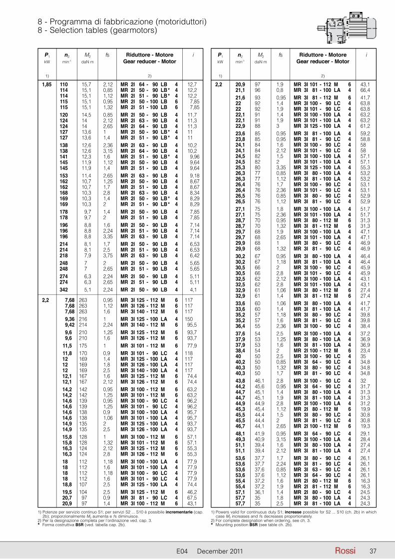
3737E04 December 2011
8 - Programma di fabbricazione (motoriduttori)8 - Selection tables (gearmotors)
P1 n2 M2 fs Riduttore - Motore i kW min-1 daN m Gear reducer - Motor
1) 2)
1) Potenze per servizio continuo S1; per servizi S2 ... S10 è possibile incrementarle (cap. 2b); proporzionalmente M2 aumenta e fs diminuisce.
2) Per la designazione completa per l’ordinazione ved. cap. 3.* Forma costruttiva B5R (ved. tabella cap. 2b).
1,85 110 15,7 2,12 MR 2I 64 - 90 LB 4 12,7 114 15,1 0,85 MR 2I 50 - 90 LB * 4 12,2 114 15,1 1,12 MR 2I 51 - 90 LB * 4 12,2 115 15,1 0,95 MR 2I 50 - 100 LB 6 7,85 115 15,1 1,32 MR 2I 51 - 100 LB 6 7,85 120 14,5 0,85 MR 2I 50 - 90 LB 4 11,7 124 14 2,12 MR 2I 63 - 90 LB 4 11,3 124 14 2,65 MR 2I 64 - 90 LB 4 11,3 127 13,6 1 MR 2I 50 - 90 LB * 4 11 127 13,6 1,4 MR 2I 51 - 90 LB * 4 11 138 12,6 2,36 MR 2I 63 - 90 LB 4 10,2 138 12,6 3,15 MR 2I 64 - 90 LB 4 10,2 141 12,3 1,6 MR 2I 51 - 90 LB * 4 9,96 145 11,9 1,12 MR 2I 50 - 90 LB 4 9,64 145 11,9 1,4 MR 2I 51 - 90 LB 4 9,64 153 11,4 2,65 MR 2I 63 - 90 LB 4 9,18 162 10,7 1,25 MR 2I 50 - 90 LB 4 8,67 162 10,7 1,7 MR 2I 51 - 90 LB 4 8,67 168 10,3 2,8 MR 2I 63 - 90 LB 4 8,34 169 10,3 1,4 MR 2I 50 - 90 LB * 4 8,29 169 10,3 2 MR 2I 51 - 90 LB * 4 8,29 178 9,7 1,4 MR 2I 50 - 90 LB 4 7,85 178 9,7 2 MR 2I 51 - 90 LB 4 7,85 196 8,8 1,6 MR 2I 50 - 90 LB 4 7,14 196 8,8 2,24 MR 2I 51 - 90 LB 4 7,14 196 8,8 3,35 MR 2I 63 - 90 LB 4 7,14 214 8,1 1,7 MR 2I 50 - 90 LB 4 6,53 214 8,1 2,5 MR 2I 51 - 90 LB 4 6,53 218 7,9 3,75 MR 2I 63 - 90 LB 4 6,42 248 7 2 MR 2I 50 - 90 LB 4 5,65 248 7 2,65 MR 2I 51 - 90 LB 4 5,65 274 6,3 2,24 MR 2I 50 - 90 LB 4 5,11 274 6,3 2,65 MR 2I 51 - 90 LB 4 5,11 342 5,1 2,24 MR 2I 50 - 90 LB 4 4,1
2,2 7,68 263 0,95 MR 3I 125 - 112 M 6 117 7,68 263 1,12 MR 3I 126 - 112 M 6 117 7,68 263 1,6 MR 3I 140 - 112 M 6 117 9,36 216 1 MR 3I 125 - 100 LA 4 150 9,42 214 2,24 MR 3I 140 - 112 M 6 95,5 9,6 210 1,25 MR 3I 125 - 112 M 6 93,7 9,6 210 1,6 MR 3I 126 - 112 M 6 93,7 11,5 175 1 MR 3I 101 - 112 M 6 77,9 11,8 170 0,9 MR 3I 101 - 90 LC 4 118 12 169 1,4 MR 3I 125 - 100 LA 4 117 12 169 1,8 MR 3I 126 - 100 LA 4 117 12 169 2,5 MR 3I 140 - 100 LA 4 117 12,1 167 1,6 MR 3I 125 - 112 M 6 74,4 12,1 167 2,12 MR 3I 126 - 112 M 6 74,4 14,2 142 0,95 MR 3I 100 - 112 M 6 63,2 14,2 142 1,25 MR 3I 101 - 112 M 6 63,2 14,6 139 0,95 MR 3I 100 - 90 LC 4 96,2 14,6 139 1,25 MR 3I 101 - 90 LC 4 96,2 14,6 138 0,9 MR 3I 100 - 100 LA 4 95,7 14,6 138 1,06 MR 3I 101 - 100 LA 4 95,7 14,9 135 2 MR 3I 125 - 100 LA 4 93,7 14,9 135 2,5 MR 3I 126 - 100 LA 4 93,7 15,8 128 1 MR 3I 100 - 112 M 6 57,1 15,8 128 1,32 MR 3I 101 - 112 M 6 57,1 16,3 124 2,12 MR 3I 125 - 112 M 6 55,3 16,3 124 2,8 MR 3I 126 - 112 M 6 55,3 18 112 1,18 MR 3I 100 - 100 LA 4 77,9 18 112 1,6 MR 3I 101 - 100 LA 4 77,9 18 112 1,18 MR 3I 100 - 90 LC 4 77,9 18 112 1,6 MR 3I 101 - 90 LC 4 77,9 18,8 107 2,5 MR 3I 125 - 100 LA 4 74,4 19,5 104 2,5 MR 3I 125 - 112 M 6 46,2 20,7 97 0,9 MR 3I 81 - 90 LC 4 67,5 20,9 97 1,4 MR 3I 100 - 112 M 6 43,1
P1 n2 M2 fs Riduttore - Motore i kW min-1 daN m Gear reducer - Motor
1) 2)
1) Powers valid for continuous duty S1; increase possible for S2 ... S10 (ch. 2b) in which case M2 increases and fs decreases proportionately.
2) For complete designation when ordering, see ch. 3.* Mounting position B5R (see table ch. 2b).
2,2 20,9 97 1,9 MR 3I 101 - 112 M 6 43,1 21,1 96 0,8 MR 3I 81 - 100 LA 4 66,4 21,6 93 0,95 MR 3I 81 - 112 M 6 41,7 22 92 1,4 MR 3I 100 - 90 LC 4 63,8 22 92 1,9 MR 3I 101 - 90 LC 4 63,8 22,1 91 1,4 MR 3I 100 - 100 LA 4 63,2 22,1 91 1,9 MR 3I 101 - 100 LA 4 63,2 22,9 88 3 MR 3I 125 - 100 LA 4 61,2 23,6 85 0,95 MR 3I 81 - 100 LA 4 59,2 23,8 85 0,95 MR 3I 81 - 90 LC 4 58,8 24,1 84 1,6 MR 3I 100 - 90 LC 4 58 24,1 84 2,12 MR 3I 101 - 90 LC 4 58 24,5 82 1,5 MR 3I 100 - 100 LA 4 57,1 24,5 82 2 MR 3I 101 - 100 LA 4 57,1 25,3 80 3,35 MR 3I 125 - 100 LA 4 55,3 26,3 77 0,85 MR 3I 80 - 100 LA 4 53,2 26,3 77 1,12 MR 3I 81 - 100 LA 4 53,2 26,4 76 1,7 MR 3I 100 - 90 LC 4 53,1 26,4 76 2,36 MR 3I 101 - 90 LC 4 53,1 26,5 76 0,85 MR 3I 80 - 90 LC 4 52,9 26,5 76 1,12 MR 3I 81 - 90 LC 4 52,9 27,1 75 1,8 MR 3I 100 - 100 LA 4 51,7 27,1 75 2,36 MR 3I 101 - 100 LA 4 51,7 28,7 70 0,95 MR 3I 80 - 112 M 6 31,3 28,7 70 1,32 MR 3I 81 - 112 M 6 31,3 29,7 68 1,9 MR 3I 100 - 100 LA 4 47,1 29,7 68 2,65 MR 3I 101 - 100 LA 4 47,1 29,9 68 1 MR 3I 80 - 90 LC 4 46,9 29,9 68 1,32 MR 3I 81 - 90 LC 4 46,9 30,2 67 0,95 MR 3I 80 - 100 LA 4 46,4 30,2 67 1,18 MR 3I 81 - 100 LA 4 46,4 30,5 66 2 MR 3I 100 - 90 LC 4 45,9 30,5 66 2,8 MR 3I 101 - 90 LC 4 45,9 32,5 62 2,12 MR 3I 100 - 100 LA 4 43,1 32,5 62 2,8 MR 3I 101 - 100 LA 4 43,1 32,9 61 1,06 MR 3I 80 - 112 M 6 27,4 32,9 61 1,4 MR 3I 81 - 112 M 6 27,4 33,6 60 1,06 MR 3I 80 - 100 LA 4 41,7 33,6 60 1,4 MR 3I 81 - 100 LA 4 41,7 35,2 57 1,18 MR 3I 80 - 90 LC 4 39,8 35,2 57 1,6 MR 3I 81 - 90 LC 4 39,8 36,4 55 2,36 MR 3I 100 - 90 LC 4 38,4 37,6 54 2,5 MR 3I 100 - 100 LA 4 37,2 37,9 53 1,25 MR 3I 80 - 100 LA 4 36,9 37,9 53 1,6 MR 3I 81 - 100 LA 4 36,9 38,4 54 2 MR 2I 100 - 112 M 6 23,4 40 50 2,5 MR 3I 100 - 90 LC 4 35 40,2 50 0,85 MR 3I 64 - 90 LC 4 34,8 40,3 50 1,32 MR 3I 80 - 90 LC 4 34,8 40,3 50 1,7 MR 3I 81 - 90 LC 4 34,8 43,8 46,1 2,8 MR 3I 100 - 90 LC 4 32 44,2 45,6 0,95 MR 3I 64 - 90 LC 4 31,7 44,7 45,1 1,4 MR 3I 80 - 100 LA 4 31,3 44,7 45,1 1,9 MR 3I 81 - 100 LA 4 31,3 44,9 44,9 2,8 MR 3I 100 - 100 LA 4 31,2 45,3 45,4 1,12 MR 2I 80 - 112 M 6 19,9 45,5 44,4 1,5 MR 3I 80 - 90 LC 4 30,8 45,5 44,4 2 MR 3I 81 - 90 LC 4 30,8 46,7 44,1 2,65 MR 2I 100 - 112 M 6 19,3 48,1 41,9 0,95 MR 3I 64 - 90 LC 4 29,1 49,3 40,9 3,15 MR 3I 100 - 100 LA 4 28,4 51,1 39,4 1,6 MR 3I 80 - 100 LA 4 27,4 51,1 39,4 2,12 MR 3I 81 - 100 LA 4 27,4 53,6 37,7 1,7 MR 3I 80 - 90 LC 4 26,1 53,6 37,7 2,24 MR 3I 81 - 90 LC 4 26,1 53,6 37,6 0,85 MR 3I 63 - 90 LC 4 26,1 53,6 37,6 1,12 MR 3I 64 - 90 LC 4 26,1 55,4 37,2 1,6 MR 2I 80 - 112 M 6 16,3 55,4 37,2 1,9 MR 2I 81 - 112 M 6 16,3 57,1 36,1 1,4 MR 2I 80 - 90 LC 4 24,5 57,7 35 1,8 MR 3I 80 - 100 LA 4 24,3 57,7 35 2,5 MR 3I 81 - 100 LA 4 24,3

38 E04 December 2011
8 - Programma di fabbricazione (motoriduttori)8 - Selection tables (gearmotors)
P1 n2 M2 fs Riduttore - Motore i kW min-1 daN m Gear reducer - Motor
1) 2)
1) Potenze per servizio continuo S1; per servizi S2 ... S10 è possibile incrementarle (cap. 2b); proporzionalmente M2 aumenta e fs diminuisce.
2) Per la designazione completa per l’ordinazione ved. cap. 3.* Forma costruttiva B5R (ved. tabella cap. 2b).
2,2 59,3 34 0,95 MR 3I 63 - 90 LC 4 23,6 59,3 34 1,25 MR 3I 64 - 90 LC 4 23,6 59,7 33,8 1,9 MR 3I 80 - 90 LC 4 23,5 59,7 33,8 2,5 MR 3I 81 - 90 LC 4 23,5 59,8 34,5 3,15 MR 2I 100 - 100 LA 4 23,4 65,2 30,9 1 MR 3I 63 - 90 LC 4 21,5 65,2 30,9 1,4 MR 3I 64 - 90 LC 4 21,5 68 29,7 2,12 MR 3I 80 - 100 LA 4 20,6 68 29,7 2,8 MR 3I 81 - 100 LA 4 20,6 68,7 29,4 2,24 MR 3I 80 - 90 LC 4 20,4 69,1 29,8 2,12 MR 2I 80 - 112 M 6 13 69,1 29,8 2,8 MR 2I 81 - 112 M 6 13 69,8 29,5 1,9 MR 2I 80 - 90 LC 4 20,1 69,8 29,5 2,36 MR 2I 81 - 90 LC 4 20,1 70,5 29,2 1,7 MR 2I 80 - 100 LA 4 19,9 70,5 29,2 0,85 MR 2I 63 - 112 M 6 12,8 75,7 26,6 2,36 MR 3I 80 - 100 LA 4 18,5 76,2 26,5 1,18 MR 3I 63 - 90 LC 4 18,4 76,2 26,5 1,6 MR 3I 64 - 90 LC 4 18,4 78,3 26,3 2,24 MR 2I 80 - 90 LC 4 17,9 84,7 23,8 1,32 MR 3I 63 - 90 LC 4 16,5 84,7 23,8 1,8 MR 3I 64 - 90 LC 4 16,5 86,2 23,9 2,36 MR 2I 80 - 100 LA 4 16,3 86,2 23,9 2,8 MR 2I 81 - 100 LA 4 16,3 86,4 23,8 1,06 MR 2I 63 - 90 LC 4 16,2 87,1 23,6 2,65 MR 2I 80 - 90 LC 4 16,1 87,2 23,1 2,8 MR 3I 80 - 100 LA 4 16,1 90 22,9 1,25 MR 2I 63 - 112 M 6 10 90 22,9 1,5 MR 2I 64 - 112 M 6 10 96,6 21,3 2,8 MR 2I 80 - 100 LA 4 14,5 96,6 21,3 2,8 MR 2I 80 - 90 LC 4 14,5 101 20,4 1,4 MR 2I 63 - 112 M 6 8,91 101 20,4 1,8 MR 2I 64 - 112 M 6 8,91 108 19,1 3,15 MR 2I 80 - 100 LA 4 13 110 18,8 1,32 MR 2I 63 - 100 LA 4 12,8 110 18,7 1,5 MR 2I 63 - 90 LC 4 12,7 110 18,7 1,8 MR 2I 64 - 90 LC 4 12,7 113 18,3 1,7 MR 2I 63 - 112 M 6 8 113 18,3 2,12 MR 2I 64 - 112 M 6 8 114 18 0,95 MR 2I 51 - 90 LC * 4 12,2 124 16,6 1,7 MR 2I 63 - 90 LC 4 11,3 124 16,6 2,24 MR 2I 64 - 90 LC 4 11,3 124 16,5 1,8 MR 2I 63 - 112 M 6 7,23 124 16,5 2,5 MR 2I 64 - 112 M 6 7,23 127 16,2 0,85 MR 2I 50 - 90 LC * 4 11 127 16,2 1,12 MR 2I 51 - 90 LC * 4 11 138 14,9 2 MR 2I 63 - 90 LC 4 10,2 138 14,9 2,65 MR 2I 64 - 90 LC 4 10,2 140 14,7 1,9 MR 2I 63 - 100 LA 4 10 140 14,7 2,24 MR 2I 64 - 100 LA 4 10 141 14,6 1,32 MR 2I 51 - 90 LC * 4 9,96 145 14,2 0,9 MR 2I 50 - 90 LC 4 9,64 145 14,2 1,18 MR 2I 51 - 90 LC 4 9,64 153 13,5 2,24 MR 2I 63 - 90 LC 4 9,18 153 13,5 3 MR 2I 64 - 90 LC 4 9,18 157 13,1 2,12 MR 2I 63 - 100 LA 4 8,91 157 13,1 2,8 MR 2I 64 - 100 LA 4 8,91 162 12,7 1,06 MR 2I 50 - 90 LC 4 8,67 162 12,7 1,4 MR 2I 51 - 90 LC 4 8,67 168 12,3 2,5 MR 2I 63 - 90 LC 4 8,34 169 12,2 1,18 MR 2I 50 - 90 LC * 4 8,29 169 12,2 1,7 MR 2I 51 - 90 LC * 4 8,29 175 11,8 2,5 MR 2I 63 - 100 LA 4 8 175 11,8 3,35 MR 2I 64 - 100 LA 4 8 178 11,5 1,18 MR 2I 50 - 90 LC 4 7,85 178 11,5 1,7 MR 2I 51 - 90 LC 4 7,85 194 10,6 2,8 MR 2I 63 - 100 LA 4 7,23 196 10,5 1,32 MR 2I 50 - 90 LC 4 7,14 196 10,5 1,9 MR 2I 51 - 90 LC 4 7,14 196 10,5 2,8 MR 2I 63 - 90 LC 4 7,14 213 9,7 3 MR 2I 63 - 100 LA 4 6,57
P1 n2 M2 fs Riduttore - Motore i kW min-1 daN m Gear reducer - Motor
1) 2)
1) Powers valid for continuous duty S1; increase possible for S2 ... S10 (ch. 2b) in which case M2 increases and fs decreases proportionately.
2) For complete designation when ordering, see ch. 3.* Mounting position B5R (see table ch. 2b).
2,2 214 9,6 1,4 MR 2I 50 - 90 LC 4 6,53 214 9,6 2,12 MR 2I 51 - 90 LC 4 6,53 218 9,4 3,15 MR 2I 63 - 90 LC 4 6,42 248 8,3 1,7 MR 2I 50 - 90 LC 4 5,65 248 8,3 2,24 MR 2I 51 - 90 LC 4 5,65 249 8,3 3,55 MR 2I 63 - 100 LA 4 5,63 274 7,5 1,9 MR 2I 50 - 90 LC 4 5,11 274 7,5 2,24 MR 2I 51 - 90 LC 4 5,11 277 7,4 4 MR 2I 63 - 100 LA 4 5,06 342 6 1,9 MR 2I 50 - 90 LC 4 4,1 342 6 2,24 MR 2I 51 - 90 LC 4 4,1 392 5,3 2,5 MR 2I 50 - 90 LA 2 7,14 392 5,3 3,55 MR 2I 51 - 90 LA 2 7,14 429 4,8 2,8 MR 2I 50 - 90 LA 2 6,53 496 4,15 3,15 MR 2I 50 - 90 LA 2 5,65 548 3,76 3,55 MR 2I 50 - 90 LA 2 5,11 684 3,01 3,75 MR 2I 50 - 90 LA 2 4,1
3 7,31 376 2,24 MR 3I 180 - 132 S 6 123 7,54 365 1,6 MR 3I 160 - 132 S 6 119 7,68 358 0,85 MR 3I 126 - 112 MC 6 117 7,68 358 1,18 MR 3I 140 - 112 MC 6 117 8,97 306 2,24 MR 3I 160 - 132 S 6 100 9,42 292 1,7 MR 3I 140 - 112 MC 6 95,5 9,6 286 0,95 MR 3I 125 - 112 MC 6 93,7 9,6 286 1,18 MR 3I 126 - 112 MC 6 93,7 10,7 256 2,65 MR 3I 160 - 132 S 6 83,8 11,9 232 2,12 MR 3I 140 - 112 MC 6 75,8 12 230 1,06 MR 3I 125 - 100 LB 4 117 12 230 1,32 MR 3I 126 - 100 LB 4 117 12 230 1,8 MR 3I 140 - 100 LB 4 117 12,1 227 1,18 MR 3I 125 - 112 MC 6 74,4 12,1 227 1,5 MR 3I 126 - 112 MC 6 74,4 14,2 193 0,9 MR 3I 101 - 112 MC 6 63,2 14,6 188 0,8 MR 3I 101 - 100 LB 4 95,7 14,7 188 2,65 MR 3I 140 - 100 LB 4 95,5 14,9 184 1,4 MR 3I 125 - 100 LB 4 93,7 14,9 184 1,9 MR 3I 126 - 100 LB 4 93,7 15,8 175 0,95 MR 3I 101 - 112 MC 6 57,1 16,2 170 3 MR 3I 140 - 112 MC 6 55,7 16,3 169 1,6 MR 3I 125 - 112 MC 6 55,3 16,3 169 2,12 MR 3I 126 - 112 MC 6 55,3 17,7 155 3,15 MR 3I 140 - 112 MC 6 50,8 18 153 0,85 MR 3I 100 - 100 LB 4 77,9 18 153 1,12 MR 3I 101 - 100 LB 4 77,9 18,8 146 1,8 MR 3I 125 - 100 LB 4 74,4 18,8 146 2,36 MR 3I 126 - 100 LB 4 74,4 19,1 144 0,9 MR 3I 100 - 112 MC 6 47,1 19,1 144 1,25 MR 3I 101 - 112 MC 6 47,1 19,3 143 3,15 MR 3I 140 - 112 MC 6 46,7 19,5 141 1,8 MR 3I 125 - 112 MC 6 46,2 19,5 141 2,36 MR 3I 126 - 112 MC 6 46,2 19,7 140 0,9 MR 3I 100 - 132 S 6 45,7 19,7 140 1,18 MR 3I 101 - 132 S 6 45,7 20,2 136 1,9 MR 3I 125 - 132 S 6 44,5 20,9 132 1 MR 3I 100 - 112 MC 6 43,1 20,9 132 1,4 MR 3I 101 - 112 MC 6 43,1 22,1 124 1,06 MR 3I 100 - 100 LB 4 63,2 22,1 124 1,4 MR 3I 101 - 100 LB 4 63,2 22,9 120 2,24 MR 3I 125 - 100 LB 4 61,2 22,9 120 2,8 MR 3I 126 - 100 LB 4 61,2 24,2 114 1,6 MR 3I 101 - 112 MC 6 37,2 24,5 112 1,12 MR 3I 100 - 100 LB 4 57,1 24,5 112 1,5 MR 3I 101 - 100 LB 4 57,1 25,3 109 2,5 MR 3I 125 - 100 LB 4 55,3 26,3 105 0,85 MR 3I 81 - 100 LB 4 53,2 27,1 102 1,32 MR 3I 100 - 100 LB 4 51,7 27,1 102 1,7 MR 3I 101 - 100 LB 4 51,7

3939E04 December 2011
8 - Programma di fabbricazione (motoriduttori)8 - Selection tables (gearmotors)
P1 n2 M2 fs Riduttore - Motore i kW min-1 daN m Gear reducer - Motor
1) 2)
1) Potenze per servizio continuo S1; per servizi S2 ... S10 è possibile incrementarle (cap. 2b); proporzionalmente M2 aumenta e fs diminuisce.
2) Per la designazione completa per l’ordinazione ved. cap. 3.* Forma costruttiva B5R (ved. tabella cap. 2b).
3 27,9 99 2,65 MR 3I 125 - 100 LB 4 50,2 29,7 93 1,4 MR 3I 100 - 100 LB 4 47,1 29,7 93 1,9 MR 3I 101 - 100 LB 4 47,1 29,9 92 0,95 MR 3I 81 - 100 LB * 4 46,9 30,2 91 0,9 MR 3I 81 - 100 LB 4 46,4 30,3 91 2,8 MR 3I 125 - 100 LB 4 46,2 32,5 85 1,5 MR 3I 100 - 100 LB 4 43,1 32,5 85 2,12 MR 3I 101 - 100 LB 4 43,1 32,9 84 1 MR 3I 81 - 112 MC 6 27,4 33,6 82 0,8 MR 3I 80 - 100 LB 4 41,7 33,6 82 1,06 MR 3I 81 - 100 LB 4 41,7 33,8 81 3,15 MR 3I 125 - 100 LB 4 41,5 34,7 79 1,6 MR 3I 100 - 112 MC 6 26 34,7 79 2,24 MR 3I 101 - 112 MC 6 26 37,1 74 0,9 MR 3I 80 - 112 MC 6 24,3 37,1 74 1,18 MR 3I 81 - 112 MC 6 24,3 37,3 74 3,55 MR 3I 125 - 100 LB 4 37,5 37,6 73 1,8 MR 3I 100 - 100 LB 4 37,2 37,6 73 2,5 MR 3I 101 - 100 LB 4 37,2 37,9 73 0,9 MR 3I 80 - 100 LB 4 36,9 37,9 73 1,18 MR 3I 81 - 100 LB 4 36,9 38,4 73 1,5 MR 2I 100 - 112 MC 6 23,4 44,7 62 1,06 MR 3I 80 - 100 LB 4 31,3 44,7 62 1,4 MR 3I 81 - 100 LB 4 31,3 44,9 61 2,12 MR 3I 100 - 100 LB 4 31,2 44,9 61 2,8 MR 3I 101 - 100 LB 4 31,2 46,7 60 1,9 MR 2I 100 - 112 MC 6 19,3 46,7 60 2,36 MR 2I 101 - 112 MC 6 19,3 49,3 56 2,24 MR 3I 100 - 100 LB 4 28,4 49,3 56 3,15 MR 3I 101 - 100 LB 4 28,4 51,1 54 1,18 MR 3I 80 - 100 LB 4 27,4 51,1 54 1,5 MR 3I 81 - 100 LB 4 27,4 53,6 51 0,8 MR 3I 64 - 100 LB * 4 26,1 53,9 51 2,5 MR 3I 100 - 100 LB 4 26 55,4 51 1,12 MR 2I 80 - 112 MC 6 16,3 55,4 51 1,4 MR 2I 81 - 112 MC 6 16,3 57,1 49,2 1,06 MR 2I 80 - 100 LB * 4 24,5 57,7 47,7 1,32 MR 3I 80 - 100 LB 4 24,3 57,7 47,7 1,8 MR 3I 81 - 100 LB 4 24,3 59,3 46,4 0,9 MR 3I 64 - 100 LB * 4 23,6 59,8 47 2,24 MR 2I 100 - 100 LB 4 23,4 62,1 45,2 1,32 MR 2I 80 - 112 MC 6 14,5 62,1 45,2 1,7 MR 2I 81 - 112 MC 6 14,5 62,4 44,1 2,8 MR 3I 100 - 100 LB 4 22,4 65,2 42,2 1 MR 3I 64 - 100 LB * 4 21,5 68 40,5 1,6 MR 3I 80 - 100 LB 4 20,6 68 40,5 2,12 MR 3I 81 - 100 LB 4 20,6 69,8 40,2 1,4 MR 2I 80 - 100 LB * 4 20,1 69,8 40,2 1,7 MR 2I 81 - 100 LB * 4 20,1 70,5 39,8 1,32 MR 2I 80 - 100 LB 4 19,9 72,6 38,7 3 MR 2I 100 - 100 LB 4 19,3 75,7 36,3 1,8 MR 3I 80 - 100 LB 4 18,5 75,7 36,3 2,36 MR 3I 81 - 100 LB 4 18,5 76,2 36,1 0,9 MR 3I 63 - 100 LB * 4 18,4 76,2 36,1 1,18 MR 3I 64 - 100 LB * 4 18,4 78,3 35,9 2,12 MR 2I 81 - 100 LB * 4 17,9 80,8 34,8 3,35 MR 2I 100 - 100 LB 4 17,3 84,7 32,5 1 MR 3I 63 - 100 LB * 4 16,5 84,7 32,5 1,32 MR 3I 64 - 100 LB * 4 16,5 86,2 32,6 1,7 MR 2I 80 - 100 LB 4 16,3 86,2 32,6 2,12 MR 2I 81 - 100 LB 4 16,3 87,1 32,2 1,9 MR 2I 80 - 100 LB * 4 16,1 87,1 32,2 2,5 MR 2I 81 - 100 LB * 4 16,1 87,2 31,6 2 MR 3I 80 - 100 LB 4 16,1 87,2 31,6 2,65 MR 3I 81 - 100 LB 4 16,1 90 31,2 0,9 MR 2I 63 - 112 MC 6 10 90 31,2 1,12 MR 2I 64 - 112 MC 6 10 96,6 29,1 2 MR 2I 80 - 100 LB 4 14,5 96,6 29,1 2,5 MR 2I 81 - 100 LB 4 14,5 101 27,8 1,06 MR 2I 63 - 112 MC 6 8,91 101 27,8 1,32 MR 2I 64 - 112 MC 6 8,91
P1 n2 M2 fs Riduttore - Motore i kW min-1 daN m Gear reducer - Motor
1) 2)
1) Powers valid for continuous duty S1; increase possible for S2 ... S10 (ch. 2b) in which case M2 increases and fs decreases proportionately.
2) For complete designation when ordering, see ch. 3.* Mounting position B5R (see table ch. 2b).
3 108 26,1 2,36 MR 2I 80 - 100 LB 4 13 108 26,1 3 MR 2I 81 - 100 LB 4 13 110 25,6 1 MR 2I 63 - 100 LB 4 12,8 110 25,5 1,12 MR 2I 63 - 100 LB * 4 12,7 110 25,5 1,32 MR 2I 64 - 100 LB * 4 12,7 113 25 1,18 MR 2I 63 - 112 MC 6 8 113 25 1,6 MR 2I 64 - 112 MC 6 8 119 23,6 2,5 MR 2I 80 - 100 LB 4 11,8 124 22,7 1,25 MR 2I 63 - 100 LB * 4 11,3 124 22,7 1,6 MR 2I 64 - 100 LB * 4 11,3 124 22,6 1,32 MR 2I 63 - 112 MC 6 7,23 124 22,6 1,8 MR 2I 64 - 112 MC 6 7,23 133 21,2 2,8 MR 2I 80 - 100 LB 4 10,6 137 20,5 2 MR 2I 64 - 112 MC 6 6,57 138 20,4 1,5 MR 2I 63 - 100 LB * 4 10,2 138 20,4 1,9 MR 2I 64 - 100 LB * 4 10,2 140 20,1 1,4 MR 2I 63 - 100 LB 4 10 140 20,1 1,7 MR 2I 64 - 100 LB 4 10 145 19,3 0,9 MR 2I 51 - 100 LB 4 9,64 150 18,8 3,15 MR 2I 80 - 100 LB 4 9,36 157 17,9 1,6 MR 2I 63 - 100 LB 4 8,91 157 17,9 2 MR 2I 64 - 100 LB 4 8,91 162 17,4 0,8 MR 2I 50 - 100 LB 4 8,67 162 17,4 1,06 MR 2I 51 - 100 LB 4 8,67 168 16,7 1,8 MR 2I 63 - 100 LB * 4 8,34 168 16,7 2,36 MR 2I 64 - 100 LB * 4 8,34 175 16 1,8 MR 2I 63 - 100 LB 4 8 175 16 2,36 MR 2I 64 - 100 LB 4 8 176 15,9 3,75 MR 2I 80 - 100 LB 4 7,95 178 15,7 0,9 MR 2I 50 - 100 LB 4 7,85 178 15,7 1,25 MR 2I 51 - 100 LB 4 7,85 194 14,5 2 MR 2I 63 - 100 LB 4 7,23 194 14,5 2,65 MR 2I 64 - 100 LB 4 7,23 196 14,3 0,95 MR 2I 50 - 100 LB 4 7,14 196 14,3 1,4 MR 2I 51 - 100 LB 4 7,14 213 13,2 2,24 MR 2I 63 - 100 LB 4 6,57 213 13,2 3 MR 2I 64 - 100 LB 4 6,57 214 13,1 1,06 MR 2I 50 - 100 LB 4 6,53 214 13,1 1,5 MR 2I 51 - 100 LB 4 6,53 225 12,5 2 MR 2I 63 - 112 MC 6 4 225 12,5 2,12 MR 2I 64 - 112 MC 6 4 248 11,3 1,25 MR 2I 50 - 100 LB 4 5,65 248 11,3 1,6 MR 2I 51 - 100 LB 4 5,65 249 11,3 2,65 MR 2I 63 - 100 LB 4 5,63 274 10,3 1,32 MR 2I 50 - 100 LB 4 5,11 274 10,3 1,6 MR 2I 51 - 100 LB 4 5,11 277 10,1 2,8 MR 2I 63 - 100 LB 4 5,06 342 8,2 1,4 MR 2I 50 - 100 LB 4 4,1 342 8,2 1,6 MR 2I 51 - 100 LB 4 4,1 350 8 3 MR 2I 63 - 100 LB 4 4 392 7,2 1,8 MR 2I 50 - 90 LB 2 7,14 429 6,6 2 MR 2I 50 - 90 LB 2 6,53 496 5,7 2,36 MR 2I 50 - 90 LB 2 5,65 548 5,1 2,65 MR 2I 50 - 90 LB 2 5,11 684 4,11 2,8 MR 2I 50 - 90 LB 2 4,1
4 7,31 501 1,7 MR 3I 180 - 132 M 6 123 7,54 487 1,25 MR 3I 160 - 132 M 6 119 8,93 411 2,36 MR 3I 180 - 132 M 6 101 8,97 409 1,7 MR 3I 160 - 132 M 6 100 10,7 343 2,8 MR 3I 180 - 132 M 6 84,2 10,7 341 2 MR 3I 160 - 132 M 6 83,8 12 307 0,8 MR 3I 125 - 112 M 4 117 12 307 1 MR 3I 126 - 112 M 4 117 12 307 1,4 MR 3I 140 - 112 M 4 117 13,7 267 2,65 MR 3I 160 - 132 M 6 65,6 14,7 250 1,9 MR 3I 140 - 112 M 4 95,5 14,9 245 1,06 MR 3I 125 - 112 M 4 93,7

40 E04 December 2011
8 - Programma di fabbricazione (motoriduttori)8 - Selection tables (gearmotors)
P1 n2 M2 fs Riduttore - Motore i kW min-1 daN m Gear reducer - Motor
1) 2)
1) Potenze per servizio continuo S1; per servizi S2 ... S10 è possibile incrementarle (cap. 2b); proporzionalmente M2 aumenta e fs diminuisce.
2) Per la designazione completa per l’ordinazione ved. cap. 3.* Forma costruttiva B5R (ved. tabella cap. 2b).
4 14,9 245 1,4 MR 3I 126 - 112 M 4 93,7 15,7 234 3 MR 3I 160 - 132 M 6 57,4 16,2 226 2 MR 3I 140 - 132 M 6 55,4 16,4 223 1,12 MR 3I 125 - 132 M 6 54,8 16,4 223 1,5 MR 3I 126 - 132 M 6 54,8 18 204 0,85 MR 3I 101 - 112 M 4 77,9 18,5 199 2,36 MR 3I 140 - 112 M 4 75,8 18,8 195 1,4 MR 3I 125 - 112 M 4 74,4 18,8 195 1,8 MR 3I 126 - 112 M 4 74,4 19,7 186 0,9 MR 3I 101 - 132 M 6 45,7 20,1 183 2,65 MR 3I 140 - 132 M 6 44,9 20,2 181 1,5 MR 3I 125 - 132 M 6 44,5 20,2 181 2 MR 3I 126 - 132 M 6 44,5 22,1 166 0,8 MR 3I 100 - 112 M 4 63,2 22,1 166 1,06 MR 3I 101 - 112 M 4 63,2 22,5 163 3 MR 3I 140 - 112 M 4 62,3 22,9 160 1,7 MR 3I 125 - 112 M 4 61,2 22,9 160 2,12 MR 3I 126 - 112 M 4 61,2 24,5 150 0,85 MR 3I 100 - 112 M 4 57,1 24,5 150 1,12 MR 3I 101 - 112 M 4 57,1 25,3 145 1,8 MR 3I 125 - 112 M 4 55,3 25,3 145 2,5 MR 3I 126 - 112 M 4 55,3 26,1 141 0,95 MR 3I 100 - 132 M 6 34,5 26,1 141 1,32 MR 3I 101 - 132 M 6 34,5 27,1 135 0,95 MR 3I 100 - 112 M 4 51,7 27,1 135 1,25 MR 3I 101 - 112 M 4 51,7 27,9 132 2 MR 3I 125 - 112 M 4 50,2 27,9 132 2,65 MR 3I 126 - 112 M 4 50,2 29,7 123 1,06 MR 3I 100 - 112 M 4 47,1 29,7 123 1,4 MR 3I 101 - 112 M 4 47,1 30,3 121 2,12 MR 3I 125 - 112 M 4 46,2 30,3 121 2,65 MR 3I 126 - 112 M 4 46,2 32,5 113 1,18 MR 3I 100 - 112 M 4 43,1 32,5 113 1,6 MR 3I 101 - 112 M 4 43,1 33,6 109 0,8 MR 3I 81 - 112 M 4 41,7 33,8 109 2,36 MR 3I 125 - 112 M 4 41,5 36,1 102 1,25 MR 3I 100 - 132 M 6 25 36,1 102 1,7 MR 3I 101 - 132 M 6 25 37,1 101 2,12 MR 2I 125 - 132 M 6 24,3 37,3 98 2,65 MR 3I 125 - 112 M 4 37,5 37,6 98 1,32 MR 3I 100 - 112 M 4 37,2 37,6 98 1,8 MR 3I 101 - 112 M 4 37,2 37,9 97 0,9 MR 3I 81 - 112 M 4 36,9 41,1 89 3 MR 3I 125 - 112 M 4 34,1 44,7 82 0,8 MR 3I 80 - 112 M 4 31,3 44,7 82 1,06 MR 3I 81 - 112 M 4 31,3 44,9 82 1,6 MR 3I 100 - 112 M 4 31,2 44,9 82 2 MR 3I 101 - 112 M 4 31,2 47,4 79 3 MR 2I 125 - 132 M 6 19 49,3 74 1,7 MR 3I 100 - 112 M 4 28,4 49,3 74 2,36 MR 3I 101 - 112 M 4 28,4 51,1 72 0,9 MR 3I 80 - 112 M 4 27,4 51,1 72 1,18 MR 3I 81 - 112 M 4 27,4 53,9 68 1,9 MR 3I 100 - 112 M 4 26 53,9 68 2,5 MR 3I 101 - 112 M 4 26 57,1 66 0,8 MR 2I 80 - 112 M * 4 24,5 57,7 64 1 MR 3I 80 - 112 M 4 24,3 57,7 64 1,32 MR 3I 81 - 112 M 4 24,3 59,8 63 1,7 MR 2I 100 - 112 M 4 23,4 60,1 62 1,7 MR 2I 100 - 132 M 6 15 62,4 59 2,12 MR 3I 100 - 112 M 4 22,4 62,4 59 3 MR 3I 101 - 112 M 4 22,4 68 54 1,18 MR 3I 80 - 112 M 4 20,6 68 54 1,6 MR 3I 81 - 112 M 4 20,6 69 53 2,36 MR 3I 100 - 112 M 4 20,3 69,8 54 1,06 MR 2I 80 - 112 M * 4 20,1 69,8 54 1,32 MR 2I 81 - 112 M * 4 20,1 70,5 53 0,95 MR 2I 80 - 112 M 4 19,9 72,6 52 2,24 MR 2I 100 - 112 M 4 19,3
P1 n2 M2 fs Riduttore - Motore i kW min-1 daN m Gear reducer - Motor
1) 2)
1) Powers valid for continuous duty S1; increase possible for S2 ... S10 (ch. 2b) in which case M2 increases and fs decreases proportionately.
2) For complete designation when ordering, see ch. 3.* Mounting position B5R (see table ch. 2b).
4 72,6 52 2,65 MR 2I 101 - 112 M 4 19,3 75,7 48,4 1,32 MR 3I 80 - 112 M 4 18,5 75,7 48,4 1,8 MR 3I 81 - 112 M 4 18,5 78,3 47,8 1,25 MR 2I 80 - 112 M * 4 17,9 78,3 47,8 1,6 MR 2I 81 - 112 M * 4 17,9 80,8 46,3 2,5 MR 2I 100 - 112 M 4 17,3 86,2 43,5 1,32 MR 2I 80 - 112 M 4 16,3 86,2 43,5 1,6 MR 2I 81 - 112 M 4 16,3 87,1 43 1,4 MR 2I 80 - 112 M * 4 16,1 87,1 43 1,9 MR 2I 81 - 112 M * 4 16,1 87,2 42,1 1,5 MR 3I 80 - 112 M 4 16,1 87,2 42,1 2 MR 3I 81 - 112 M 4 16,1 89,2 42 3 MR 2I 100 - 112 M 4 15,7 96,6 38,7 1,5 MR 2I 80 - 112 M 4 14,5 96,6 38,7 1,9 MR 2I 81 - 112 M 4 14,5 102 36,8 3,15 MR 2I 100 - 112 M 4 13,8 108 34,8 1,7 MR 2I 80 - 112 M 4 13 108 34,8 2,24 MR 2I 81 - 112 M 4 13 110 33,9 1 MR 2I 64 - 112 M * 4 12,7 112 33,3 3,55 MR 2I 100 - 112 M 4 12,5 119 31,4 1,8 MR 2I 80 - 112 M 4 11,8 119 31,4 2,36 MR 2I 81 - 112 M 4 11,8 121 30,9 2 MR 2I 80 - 112 M * 4 11,5 121 30,9 2,65 MR 2I 81 - 112 M * 4 11,5 124 30,3 4 MR 2I 100 - 112 M 4 11,3 124 30,2 0,95 MR 2I 63 - 112 M * 4 11,3 124 30,2 1,18 MR 2I 64 - 112 M * 4 11,3 133 28,3 2,12 MR 2I 80 - 112 M 4 10,6 133 28,3 2,8 MR 2I 81 - 112 M 4 10,6 138 27,2 1,12 MR 2I 63 - 112 M * 4 10,2 138 27,2 1,4 MR 2I 64 - 112 M * 4 10,2 140 26,7 1,06 MR 2I 63 - 112 M 4 10 140 26,7 1,25 MR 2I 64 - 112 M 4 10 150 25 2,36 MR 2I 80 - 112 M 4 9,36 150 25 3,15 MR 2I 81 - 112 M 4 9,36 157 23,8 1,18 MR 2I 63 - 112 M 4 8,91 157 23,8 1,5 MR 2I 64 - 112 M 4 8,91 158 23,8 2,5 MR 2I 80 - 132 M 6 5,71 168 22,3 1,32 MR 2I 63 - 112 M * 4 8,34 168 22,3 1,8 MR 2I 64 - 112 M * 4 8,34 175 21,4 1,4 MR 2I 63 - 112 M 4 8 175 21,4 1,8 MR 2I 64 - 112 M 4 8 176 21,2 2,8 MR 2I 80 - 112 M 4 7,95 178 21 0,9 MR 2I 51 - 112 M 4 7,85 194 19,3 1,5 MR 2I 63 - 112 M 4 7,23 194 19,3 2 MR 2I 64 - 112 M 4 7,23 196 19,1 1,06 MR 2I 51 - 112 M 4 7,14 196 19,1 3,15 MR 2I 80 - 112 M 4 7,13 213 17,6 1,7 MR 2I 63 - 112 M 4 6,57 213 17,6 2,24 MR 2I 64 - 112 M 4 6,57 214 17,5 1,12 MR 2I 51 - 112 M 4 6,53 226 16,6 3,55 MR 2I 80 - 112 M 4 6,2 248 15,1 1,25 MR 2I 51 - 112 M 4 5,65 249 15 2 MR 2I 63 - 112 M 4 5,63 249 15 2,36 MR 2I 64 - 112 M 4 5,63 274 13,7 1,25 MR 2I 51 - 112 M 4 5,11 277 13,5 2,12 MR 2I 63 - 112 M 4 5,06 277 13,5 2,36 MR 2I 64 - 112 M 4 5,06 342 11 1,25 MR 2I 51 - 112 M 4 4,1 350 10,7 2,24 MR 2I 63 - 112 M 4 4 350 10,7 2,36 MR 2I 64 - 112 M 4 4
5,5 7,31 689 1,25 MR 3I 180 - 132 MB 6 123 7,54 669 0,9 MR 3I 160 - 132 MB 6 119 8,93 565 1,7 MR 3I 180 - 132 MB 6 101 8,97 562 1,25 MR 3I 160 - 132 MB 6 100 10,7 472 2 MR 3I 180 - 132 MB 6 84,2 10,7 469 1,5 MR 3I 160 - 132 MB 6 83,8 11,4 443 1,9 MR 3I 180 - 132 S 4 123

4141E04 December 2011
8 - Programma di fabbricazione (motoriduttori)8 - Selection tables (gearmotors)
P1 n2 M2 fs Riduttore - Motore i kW min-1 daN m Gear reducer - Motor
1) 2)
1) Potenze per servizio continuo S1; per servizi S2 ... S10 è possibile incrementarle (cap. 2b); proporzionalmente M2 aumenta e fs diminuisce.
2) Per la designazione completa per l’ordinazione ved. cap. 3.
5,5 11,7 430 1,4 MR 3I 160 - 132 S 4 119 12 422 1 MR 3I 140 - 112 MC 4 117 12 419 1 MR 3I 140 - 132 MB 6 74,8 13,9 363 2,65 MR 3I 180 - 132 S 4 101 14 361 1,9 MR 3I 160 - 132 S 4 100 14,7 344 1,4 MR 3I 140 - 112 MC 4 95,5 14,9 338 0,8 MR 3I 125 - 112 MC 4 93,7 14,9 338 1 MR 3I 126 - 112 MC 4 93,7 16,2 310 1,5 MR 3I 140 - 132 MB 6 55,4 16,4 307 0,85 MR 3I 125 - 132 MB 6 54,8 16,4 307 1,06 MR 3I 126 - 132 MB 6 54,8 16,6 303 3 MR 3I 180 - 132 S 4 84,2 16,7 302 2,24 MR 3I 160 - 132 S 4 83,8 17,9 281 1,7 MR 3I 140 - 132 MB 6 50,2 18,1 279 2,5 MR 3I 160 - 132 MB 6 49,7 18,3 276 0,95 MR 3I 125 - 132 MB 6 49,3 18,3 276 1,25 MR 3I 126 - 132 MB 6 49,3 18,5 273 1,8 MR 3I 140 - 112 MC 4 75,8 18,7 270 0,9 MR 3I 125 - 132 S 4 74,8 18,7 270 1,12 MR 3I 126 - 132 S 4 74,8 18,7 270 1,6 MR 3I 140 - 132 S 4 74,8 18,8 268 1 MR 3I 125 - 112 MC 4 74,4 18,8 268 1,32 MR 3I 126 - 112 MC 4 74,4 20,1 251 2 MR 3I 140 - 132 MB 6 44,9 20,2 249 1,06 MR 3I 125 - 132 MB 6 44,5 20,2 249 1,4 MR 3I 126 - 132 MB 6 44,5 20,9 242 2,8 MR 3I 160 - 132 MB 6 43,1 21,3 236 3 MR 3I 160 - 132 S 4 65,6 22,5 225 2,12 MR 3I 140 - 112 MC 4 62,3 22,9 220 1,18 MR 3I 125 - 112 MC 4 61,2 22,9 220 1,6 MR 3I 126 - 112 MC 4 61,2 22,9 220 2,12 MR 3I 140 - 132 S 4 61 23,4 216 1,25 MR 3I 125 - 132 S 4 59,9 23,4 216 1,6 MR 3I 126 - 132 S 4 59,9 23,9 211 0,85 MR 3I 101 - 132 MB 6 37,7 24,4 207 3,35 MR 3I 160 - 132 S 4 57,4 24,5 206 0,8 MR 3I 101 - 112 MC 4 57,1 25,1 201 2,5 MR 3I 140 - 112 MC 4 55,7 25,3 200 2,24 MR 3I 140 - 132 S 4 55,4 25,3 199 1,32 MR 3I 125 - 112 MC 4 55,3 25,3 199 1,8 MR 3I 126 - 112 MC 4 55,3 25,5 198 1,32 MR 3I 125 - 132 S 4 54,8 25,5 198 1,6 MR 3I 126 - 132 S 4 54,8 26,1 193 0,95 MR 3I 101 - 132 MB 6 34,5 27,1 186 0,95 MR 3I 101 - 112 MC 4 51,7 27,6 183 2,65 MR 3I 140 - 112 MC 4 50,8 27,6 182 0,95 MR 3I 101 - 132 S 4 50,6 27,9 181 1,5 MR 3I 125 - 112 MC 4 50,2 27,9 181 2 MR 3I 126 - 112 MC 4 50,2 27,9 181 2,65 MR 3I 140 - 132 S 4 50,2 28,4 177 1,5 MR 3I 125 - 132 S 4 49,3 28,4 177 1,9 MR 3I 126 - 132 S 4 49,3 29,7 170 0,8 MR 3I 100 - 112 MC 4 47,1 29,7 170 1,06 MR 3I 101 - 112 MC 4 47,1 30 168 2,65 MR 3I 140 - 112 MC 4 46,7 30,3 166 1,5 MR 3I 125 - 112 MC 4 46,2 30,3 166 1,9 MR 3I 126 - 112 MC 4 46,2 30,6 165 1 MR 3I 101 - 132 S 4 45,7 31,2 162 3 MR 3I 140 - 132 S 4 44,9 31,4 160 1,6 MR 3I 125 - 132 S 4 44,5 31,4 160 2,24 MR 3I 126 - 132 S 4 44,5 32,5 155 0,85 MR 3I 100 - 112 MC 4 43,1 32,5 155 1,12 MR 3I 101 - 112 MC 4 43,1 33,8 149 1,7 MR 3I 125 - 112 MC 4 41,5 33,8 149 2,24 MR 3I 126 - 112 MC 4 41,5 33,8 149 0,85 MR 3I 100 - 132 S 4 41,4 33,8 149 1,12 MR 3I 101 - 132 S 4 41,4 34,6 146 1,8 MR 3I 125 - 132 S 4 40,5 34,6 146 2,36 MR 3I 126 - 132 S 4 40,5 37,1 139 1,5 MR 2I 125 - 132 MB 6 24,3 37,1 136 0,95 MR 3I 100 - 132 S 4 37,7
P1 n2 M2 fs Riduttore - Motore i kW min-1 daN m Gear reducer - Motor
1) 2)
1) Powers valid for continuous duty S1; increase possible for S2 ... S10 (ch. 2b) in which case M2 increases and fs decreases proportionately.
2) For complete designation when ordering, see ch. 3.
5,5 37,1 136 1,32 MR 3I 101 - 132 S 4 37,7 37,3 135 3,35 MR 3I 140 - 132 S 4 37,6 37,3 135 1,9 MR 3I 125 - 112 MC 4 37,5 37,3 135 2,5 MR 3I 126 - 112 MC 4 37,5 37,6 134 1 MR 3I 100 - 112 MC 4 37,2 37,6 134 1,32 MR 3I 101 - 112 MC 4 37,2 37,6 134 1,9 MR 3I 125 - 132 S 4 37,2 37,6 134 2,36 MR 3I 126 - 132 S 4 37,2 40,6 124 1,06 MR 3I 100 - 132 S 4 34,5 40,6 124 1,4 MR 3I 101 - 132 S 4 34,5 41,1 123 2,12 MR 3I 125 - 112 MC 4 34,1 41,9 120 2,12 MR 3I 125 - 132 S 4 33,4 41,9 120 2,8 MR 3I 126 - 132 S 4 33,4 44,7 113 0,8 MR 3I 81 - 112 MC 4 31,3 44,9 112 1,12 MR 3I 100 - 112 MC 4 31,2 44,9 112 1,5 MR 3I 101 - 112 MC 4 31,2 46,4 109 2,36 MR 3I 125 - 132 S 4 30,2 47 107 1,18 MR 3I 100 - 132 S 4 29,8 47 107 1,6 MR 3I 101 - 132 S 4 29,8 47,4 109 2,12 MR 2I 125 - 132 MB 6 19 49,3 102 1,25 MR 3I 100 - 112 MC 4 28,4 49,3 102 1,7 MR 3I 101 - 112 MC 4 28,4 51 99 2,65 MR 3I 125 - 132 S 4 27,4 51,1 99 0,85 MR 3I 81 - 112 MC 4 27,4 53,9 93 1,32 MR 3I 100 - 112 MC 4 26 53,9 93 1,8 MR 3I 101 - 112 MC 4 26 56,1 90 1,4 MR 3I 100 - 132 S 4 25 56,1 90 1,8 MR 3I 101 - 132 S 4 25 57,7 87 1 MR 3I 81 - 112 MC 4 24,3 57,7 89 2,36 MR 2I 125 - 132 S 4 24,3 59,6 85 3 MR 3I 125 - 132 S 4 23,5 59,8 86 1,25 MR 2I 100 - 112 MC 4 23,4 60,1 86 1,25 MR 2I 100 - 132 MB 6 15 61,6 82 1,5 MR 3I 100 - 132 S 4 22,7 61,6 82 2,12 MR 3I 101 - 132 S 4 22,7 62,4 81 1,6 MR 3I 100 - 112 MC 4 22,4 62,4 81 2,12 MR 3I 101 - 112 MC 4 22,4 66,3 76 3,35 MR 3I 125 - 132 S 4 21,1 67,4 75 1,7 MR 3I 100 - 132 S 4 20,8 67,4 75 2,24 MR 3I 101 - 132 S 4 20,8 68 74 0,85 MR 3I 80 - 112 MC 4 20,6 68 74 1,18 MR 3I 81 - 112 MC 4 20,6 69 73 1,7 MR 3I 100 - 112 MC 4 20,3 69 73 2,36 MR 3I 101 - 112 MC 4 20,3 72,6 71 1,6 MR 2I 100 - 112 MC 4 19,3 72,6 71 2 MR 2I 101 - 112 MC 4 19,3 73,1 70 1,6 MR 2I 100 - 132 MB 6 12,3 73,1 70 2 MR 2I 101 - 132 MB 6 12,3 73,7 70 3,35 MR 2I 125 - 132 S 4 19 75,7 67 0,95 MR 3I 80 - 112 MC 4 18,5 75,7 67 1,32 MR 3I 81 - 112 MC 4 18,5 77,9 65 1,9 MR 3I 100 - 132 S 4 18 77,9 65 2,65 MR 3I 101 - 132 S 4 18 80,8 64 1,9 MR 2I 100 - 112 MC 4 17,3 80,8 64 2,36 MR 2I 101 - 112 MC 4 17,3 85,2 60 1,12 MR 2I 81 - 132 MB 6 10,6 86,1 59 2,12 MR 3I 100 - 132 S 4 16,3 86,1 59 3 MR 3I 101 - 132 S 4 16,3 86,2 60 1,18 MR 2I 81 - 112 MC 4 16,3 87,2 58 1,12 MR 3I 80 - 112 MC 4 16,1 87,2 58 1,5 MR 3I 81 - 112 MC 4 16,1 89,2 58 2,12 MR 2I 100 - 112 MC 4 15,7 89,2 58 2,8 MR 2I 101 - 112 MC 4 15,7 93,5 55 1,9 MR 2I 100 - 132 S 4 15 96,6 53 1,12 MR 2I 80 - 112 MC 4 14,5 96,6 53 1,4 MR 2I 81 - 112 MC 4 14,5 102 51 2,36 MR 2I 100 - 112 MC 4 13,8 106 48,4 1,25 MR 2I 80 - 132 MB 6 8,46 106 48,4 1,6 MR 2I 81 - 132 MB 6 8,46 108 47,9 1,25 MR 2I 80 - 112 MC 4 13 108 47,9 1,7 MR 2I 81 - 112 MC 4 13

42 E04 December 2011
8 - Programma di fabbricazione (motoriduttori)8 - Selection tables (gearmotors)
P1 n2 M2 fs Riduttore - Motore i kW min-1 daN m Gear reducer - Motor
1) 2)
1) Potenze per servizio continuo S1; per servizi S2 ... S10 è possibile incrementarle (cap. 2b); proporzionalmente M2 aumenta e fs diminuisce.
2) Per la designazione completa per l’ordinazione ved. cap. 3.* Forma costruttiva B5R (ved. tabella cap. 2b).
5,5 108 47,5 1,06 MR 2I 80 - 132 S 4 12,9 112 45,8 2,65 MR 2I 100 - 112 MC 4 12,5 114 45,3 2,5 MR 2I 100 - 132 S 4 12,3 114 45,3 3 MR 2I 101 - 132 S 4 12,3 119 43,2 1,32 MR 2I 80 - 112 MC 4 11,8 119 43,2 1,7 MR 2I 81 - 112 MC 4 11,8 120 42,9 1,4 MR 2I 80 - 132 MB 6 7,5 120 42,9 1,9 MR 2I 81 - 132 MB 6 7,5 124 41,7 2,8 MR 2I 100 - 112 MC 4 11,3 126 40,7 2,8 MR 2I 100 - 132 S 4 11,1 133 38,8 1,5 MR 2I 80 - 112 MC 4 10,6 133 38,8 2 MR 2I 81 - 112 MC 4 10,6 133 38,8 1,4 MR 2I 80 - 132 S 4 10,6 133 38,8 1,7 MR 2I 81 - 132 S 4 10,6 135 38,1 3,15 MR 2I 100 - 112 MC 4 10,4 140 36,9 3,15 MR 2I 100 - 132 S 4 10 140 36,8 0,9 MR 2I 64 - 112 MC 4 10 141 36,4 2,24 MR 2I 81 - 132 MB 6 6,36 149 34,6 1,7 MR 2I 80 - 132 S 4 9,41 149 34,6 2,12 MR 2I 81 - 132 S 4 9,41 150 34,4 1,7 MR 2I 80 - 112 MC 4 9,36 150 34,4 2,36 MR 2I 81 - 112 MC 4 9,36 153 33,6 3,55 MR 2I 100 - 132 S 4 9,13 157 32,8 0,85 MR 2I 63 - 112 MC 4 8,91 157 32,8 1,12 MR 2I 64 - 112 MC 4 8,91 165 31,1 1,9 MR 2I 80 - 132 S 4 8,46 165 31,1 2,5 MR 2I 81 - 132 S 4 8,46 175 29,4 1 MR 2I 63 - 112 MC 4 8 175 29,4 1,32 MR 2I 64 - 112 MC 4 8 176 29,2 2 MR 2I 80 - 112 MC 4 7,95 176 29,2 2,8 MR 2I 81 - 112 MC 4 7,95 187 27,6 2,12 MR 2I 80 - 132 S 4 7,5 187 27,6 2,8 MR 2I 81 - 132 S 4 7,5 194 26,6 1,12 MR 2I 63 - 112 MC 4 7,23 194 26,6 1,5 MR 2I 64 - 112 MC 4 7,23 196 26,2 2,24 MR 2I 80 - 112 MC 4 7,13 196 26,2 3 MR 2I 81 - 112 MC 4 7,13 213 24,2 1,18 MR 2I 63 - 112 MC 4 6,57 213 24,2 1,6 MR 2I 64 - 112 MC 4 6,57 220 23,4 2,5 MR 2I 80 - 132 S 4 6,36 226 22,8 2,65 MR 2I 80 - 112 MC 4 6,2 245 21 2,8 MR 2I 80 - 132 S 4 5,71 249 20,7 1,4 MR 2I 63 - 112 MC 4 5,63 249 20,7 1,8 MR 2I 64 - 112 MC 4 5,63 277 18,6 1,6 MR 2I 63 - 112 MC 4 5,06 277 18,6 1,8 MR 2I 64 - 112 MC 4 5,06 282 18,2 3,15 MR 2I 80 - 132 S 4 4,96 350 14,7 1,7 MR 2I 63 - 112 MC 4 4 350 14,7 1,8 MR 2I 64 - 112 MC 4 4 353 14,6 3,35 MR 2I 80 - 132 S 4 3,96
7,5 7,31 940 0,9 MR 3I 180 - 132 MC 6 123 8,76 785 1,06 MR 3I 180 - 160 M 6 103 8,93 770 1,25 MR 3I 180 - 132 MC 6 101 8,97 766 0,9 MR 3I 160 - 132 MC 6 100 10,7 643 1,5 MR 3I 180 - 160 M 6 84,2 10,7 640 1,06 MR 3I 160 - 160 M 6 83,8 11,4 604 1,4 MR 3I 180 - 132 M 4 123 11,7 587 1 MR 3I 160 - 132 M 4 119 13,9 495 1,9 MR 3I 180 - 132 M 4 101 14 493 1,4 MR 3I 160 - 132 M 4 100 14,7 466 1,06 MR 3I 140 - 132 MC 6 61 14,7 466 1,06 MR 3I 140 - 160 M 6 61 16,2 423 1,12 MR 3I 140 - 132 MC 6 55,4 16,2 423 1,12 MR 3I 140 - 160 M 6 55,4 16,4 419 0,8 MR 3I 126 - 132 MC 6 54,8 16,6 413 2,24 MR 3I 180 - 132 M 4 84,2 16,7 411 1,7 MR 3I 160 - 132 M 4 83,8 17 404 1,7 MR 3I 160 - 160 M 6 52,8 17,9 384 1,25 MR 3I 140 - 132 MC 6 50,2
P1 n2 M2 fs Riduttore - Motore i kW min-1 daN m Gear reducer - Motor
1) 2)
1) Powers valid for continuous duty S1; increase possible for S2 ... S10 (ch. 2b) in which case M2 increases and fs decreases proportionately.
2) For complete designation when ordering, see ch. 3.* Mounting position B5R (see table ch. 2b).
7,5 18,1 380 1,9 MR 3I 160 - 132 MC 6 49,7 18,3 376 0,9 MR 3I 126 - 132 MC 6 49,3 18,3 376 0,9 MR 3I 126 - 160 M 6 49,3 18,5 372 2,5 MR 3I 180 - 132 MC 6 48,7 18,7 368 0,8 MR 3I 126 - 132 M 4 74,8 18,7 368 1,18 MR 3I 140 - 132 M 4 74,8 20,1 343 1,4 MR 3I 140 - 132 MC 6 44,9 20,2 340 0,8 MR 3I 125 - 132 MC 6 44,5 20,2 340 1,06 MR 3I 126 - 132 MC 6 44,5 20,8 331 1,4 MR 3I 140 - 160 M 6 43,4 20,9 329 2,12 MR 3I 160 - 132 MC 6 43,1 21,2 324 3 MR 3I 180 - 160 M 6 42,5 21,2 324 3 MR 3I 180 - 132 M 4 65,9 21,3 322 2,12 MR 3I 160 - 132 M 4 65,6 22,9 300 1,6 MR 3I 140 - 132 M 4 61 23,4 294 0,9 MR 3I 125 - 132 M 4 59,9 23,4 294 1,18 MR 3I 126 - 132 M 4 59,9 24,4 282 2,5 MR 3I 160 - 132 M 4 57,4 25,3 272 1,7 MR 3I 140 - 132 M 4 55,4 25,5 269 0,95 MR 3I 125 - 132 M 4 54,8 25,5 269 1,18 MR 3I 126 - 132 M 4 54,8 25,8 266 1,32 MR 3I 126 - 160 M 6 34,8 26,4 260 1,9 MR 3I 140 - 132 MC 6 34 27,9 247 1,9 MR 3I 140 - 132 M 4 50,2 28,2 244 3 MR 3I 160 - 132 M 4 49,7 28,4 242 1,06 MR 3I 125 - 132 M 4 49,3 28,4 242 1,4 MR 3I 126 - 132 M 4 49,3 29,6 232 2,12 MR 3I 140 - 132 MC 6 30,4 30,2 228 0,8 MR 3I 101 - 132 MC 6 29,8 31,2 220 2,24 MR 3I 140 - 132 M 4 44,9 31,4 219 1,18 MR 3I 125 - 132 M 4 44,5 31,4 219 1,6 MR 3I 126 - 132 M 4 44,5 32,5 212 3,15 MR 3I 160 - 132 M 4 43,1 33,8 203 0,85 MR 3I 101 - 132 M 4 41,4 34,3 201 2,36 MR 3I 140 - 132 M 4 40,9 34,6 199 1,32 MR 3I 125 - 132 M 4 40,5 34,6 199 1,8 MR 3I 126 - 132 M 4 40,5 37,1 185 0,95 MR 3I 101 - 132 M 4 37,7 37,3 185 2,36 MR 3I 140 - 132 M 4 37,6 37,6 183 1,32 MR 3I 125 - 132 M 4 37,2 37,6 183 1,7 MR 3I 126 - 132 M 4 37,2 40,6 169 1,06 MR 3I 101 - 132 M 4 34,5 41,1 167 2,8 MR 3I 140 - 132 M 4 34 41,9 164 1,6 MR 3I 125 - 132 M 4 33,4 41,9 164 2 MR 3I 126 - 132 M 4 33,4 44,4 158 1,32 MR 2I 125 - 160 M 6 20,3 46 149 3,15 MR 3I 140 - 132 M 4 30,4 46,4 148 1,7 MR 3I 125 - 132 M 4 30,2 46,4 148 2,36 MR 3I 126 - 132 M 4 30,2 47 146 0,9 MR 3I 100 - 132 M 4 29,8 47 146 1,18 MR 3I 101 - 132 M 4 29,8 47,4 148 1,6 MR 2I 125 - 132 MC 6 19 50,1 137 0,95 MR 3I 100 - 132 MC 6 18 50,1 137 1,25 MR 3I 101 - 132 MC 6 18 51 135 1,9 MR 3I 125 - 132 M 4 27,4 51 135 2,5 MR 3I 126 - 132 M 4 27,4 56,1 123 1 MR 3I 100 - 132 M 4 25 56,1 123 1,32 MR 3I 101 - 132 M 4 25 56,7 124 1,9 MR 2I 125 - 160 M 6 15,9 57,7 122 1,7 MR 2I 125 - 132 M 4 24,3 59,2 119 2,12 MR 2I 125 - 132 MC 6 15,2 59,6 115 2,24 MR 3I 125 - 132 M 4 23,5 59,6 115 3 MR 3I 126 - 132 M 4 23,5 59,8 117 0,9 MR 2I 100 - 132 M * 4 23,4 60,1 117 0,9 MR 2I 100 - 132 MC 6 15 60,1 117 0,9 MR 2I 100 - 160 M 6 15 61,6 112 1,12 MR 3I 100 - 132 M 4 22,7 61,6 112 1,5 MR 3I 101 - 132 M 4 22,7 63,7 110 2,24 MR 2I 125 - 132 MC 6 14,1 66,3 104 2,5 MR 3I 125 - 132 M 4 21,1 67,4 102 1,25 MR 3I 100 - 132 M 4 20,8

4343E04 December 2011
8 - Programma di fabbricazione (motoriduttori)8 - Selection tables (gearmotors)
P1 n2 M2 fs Riduttore - Motore i kW min-1 daN m Gear reducer - Motor
1) 2)
1) Potenze per servizio continuo S1; per servizi S2 ... S10 è possibile incrementarle (cap. 2b); proporzionalmente M2 aumenta e fs diminuisce.
2) Per la designazione completa per l’ordinazione ved. cap. 3.
7,5 67,4 102 1,7 MR 3I 101 - 132 M 4 20,8 72,6 97 1,18 MR 2I 100 - 132 M * 4 19,3 72,6 97 1,4 MR 2I 101 - 132 M * 4 19,3 73,1 96 1,18 MR 2I 100 - 132 MC 6 12,3 73,1 96 1,4 MR 2I 101 - 132 MC 6 12,3 73,1 96 1,18 MR 2I 100 - 160 M 6 12,3 73,1 96 1,4 MR 2I 101 - 160 M 6 12,3 73,7 95 2,36 MR 2I 125 - 132 M 4 19 73,7 95 3 MR 2I 126 - 132 M 4 19 77,9 88 1,4 MR 3I 100 - 132 M 4 18 77,9 88 1,9 MR 3I 101 - 132 M 4 18 80,8 87 1,4 MR 2I 100 - 132 M * 4 17,3 80,8 87 1,7 MR 2I 101 - 132 M * 4 17,3 81,3 86 1,4 MR 2I 100 - 132 MC 6 11,1 81,3 86 1,7 MR 2I 101 - 132 MC 6 11,1 81,3 86 1,4 MR 2I 100 - 160 M 6 11,1 81,3 86 1,7 MR 2I 101 - 160 M 6 11,1 82,7 85 2,8 MR 2I 125 - 132 M 4 16,9 86,1 80 1,6 MR 3I 100 - 132 M 4 16,3 86,1 80 2,12 MR 3I 101 - 132 M 4 16,3 86,2 81 0,85 MR 2I 81 - 132 M * 4 16,3 89,2 79 1,6 MR 2I 100 - 132 M * 4 15,7 89,2 79 2 MR 2I 101 - 132 M * 4 15,7 89,8 78 1,6 MR 2I 100 - 132 MC 6 10 89,8 78 2 MR 2I 101 - 132 MC 6 10 89,8 78 2 MR 2I 101 - 160 M 6 10 92,1 76 3,15 MR 2I 125 - 132 M 4 15,2 93,5 75 1,4 MR 2I 100 - 132 M 4 15 96,6 73 0,8 MR 2I 80 - 132 M * 4 14,5 96,6 73 1 MR 2I 81 - 132 M * 4 14,5 98,6 71 1,7 MR 2I 100 - 132 MC 6 9,13 98,6 71 2,36 MR 2I 101 - 132 MC 6 9,13 99 71 3,35 MR 2I 125 - 132 M 4 14,1 102 69 1,7 MR 2I 100 - 132 M * 4 13,8 102 69 2,12 MR 2I 101 - 132 M * 4 13,8 104 68 1,7 MR 2I 100 - 160 M 6 8,67 104 68 2,24 MR 2I 101 - 160 M 6 8,67 108 65 0,95 MR 2I 80 - 132 M * 4 13 108 65 1,18 MR 2I 81 - 132 M * 4 13 108 65 0,8 MR 2I 80 - 132 M 4 12,9 110 64 3,75 MR 2I 125 - 132 M 4 12,7 112 62 1,9 MR 2I 100 - 132 M * 4 12,5 112 62 2,5 MR 2I 101 - 132 M * 4 12,5 114 62 1,8 MR 2I 100 - 132 M 4 12,3 114 62 2,24 MR 2I 101 - 132 M 4 12,3 119 59 1 MR 2I 80 - 132 M * 4 11,8 119 59 1,25 MR 2I 81 - 132 M * 4 11,8 120 58 1,4 MR 2I 81 - 132 MC 6 7,5 126 56 2,12 MR 2I 100 - 132 M 4 11,1 126 56 2,65 MR 2I 101 - 132 M 4 11,1 133 53 1,12 MR 2I 80 - 132 M * 4 10,6 133 53 1,5 MR 2I 81 - 132 M * 4 10,6 133 53 1,06 MR 2I 80 - 132 M 4 10,6 133 53 1,25 MR 2I 81 - 132 M 4 10,6 140 50 2,36 MR 2I 100 - 132 M 4 10 140 50 3,15 MR 2I 101 - 132 M 4 10 149 47,2 1,18 MR 2I 80 - 132 M 4 9,41 149 47,2 1,5 MR 2I 81 - 132 M 4 9,41 150 46,9 1,25 MR 2I 80 - 132 M * 4 9,36 150 46,9 1,7 MR 2I 81 - 132 M * 4 9,36 153 45,8 2,65 MR 2I 100 - 132 M 4 9,13 165 42,4 1,4 MR 2I 80 - 132 M 4 8,46 165 42,4 1,8 MR 2I 81 - 132 M 4 8,46 168 41,9 2,8 MR 2I 100 - 132 M 4 8,35 175 40,1 0,95 MR 2I 64 - 132 M 4 8 187 37,6 1,6 MR 2I 80 - 132 M 4 7,5 187 37,6 2,12 MR 2I 81 - 132 M 4 7,5 194 36,3 1,06 MR 2I 64 - 132 M 4 7,23 194 36,2 3,35 MR 2I 100 - 132 M 4 7,22 196 35,8 1,7 MR 2I 80 - 132 M * 4 7,13 196 35,8 2,24 MR 2I 81 - 132 M * 4 7,13
P1 n2 M2 fs Riduttore - Motore i kW min-1 daN m Gear reducer - Motor
1) 2)
1) Powers valid for continuous duty S1; increase possible for S2 ... S10 (ch. 2b) in which case M2 increases and fs decreases proportionately.
2) For complete designation when ordering, see ch. 3.
7,5 213 32,9 1,18 MR 2I 64 - 132 M 4 6,57 220 31,9 1,8 MR 2I 80 - 132 M 4 6,36 220 31,9 2,5 MR 2I 81 - 132 M 4 6,36 245 28,6 2 MR 2I 80 - 132 M 4 5,71 245 28,6 2,5 MR 2I 81 - 132 M 4 5,71 249 28,2 1,32 MR 2I 64 - 132 M 4 5,63 277 25,4 1,32 MR 2I 64 - 132 M 4 5,06 282 24,9 2,36 MR 2I 80 - 132 M 4 4,96 282 24,9 2,5 MR 2I 81 - 132 M 4 4,96 350 20,1 1,32 MR 2I 64 - 132 M 4 4 353 19,9 2,5 MR 2I 80 - 132 M 4 3,96
9,2 11,4 741 1,12 MR 3I 180 - 132 MB 4 123 11,7 720 0,85 MR 3I 160 - 132 MB 4 119 13,9 607 1,5 MR 3I 180 - 132 MB 4 101 14 604 1,12 MR 3I 160 - 132 MB 4 100 16,6 507 1,8 MR 3I 180 - 132 MB 4 84,2 16,7 505 1,4 MR 3I 160 - 132 MB 4 83,8 18,7 451 0,95 MR 3I 140 - 132 MB 4 74,8 21,2 397 2,5 MR 3I 180 - 132 MB 4 65,9 21,3 395 1,7 MR 3I 160 - 132 MB 4 65,6 22,9 368 1,32 MR 3I 140 - 132 MB 4 61 23,4 361 0,95 MR 3I 126 - 132 MB 4 59,9 24,4 346 2 MR 3I 160 - 132 MB 4 57,4 24,5 344 2,8 MR 3I 180 - 132 MB 4 57,1 25,3 334 1,4 MR 3I 140 - 132 MB 4 55,4 25,5 330 0,95 MR 3I 126 - 132 MB 4 54,8 27,9 302 1,6 MR 3I 140 - 132 MB 4 50,2 28,2 300 2,36 MR 3I 160 - 132 MB 4 49,7 28,4 297 0,9 MR 3I 125 - 132 MB 4 49,3 28,4 297 1,12 MR 3I 126 - 132 MB 4 49,3 28,8 293 3,15 MR 3I 180 - 132 MB 4 48,7 31,2 270 1,8 MR 3I 140 - 132 MB 4 44,9 31,4 268 1 MR 3I 125 - 132 MB 4 44,5 31,4 268 1,32 MR 3I 126 - 132 MB 4 44,5 32,5 260 2,65 MR 3I 160 - 132 MB 4 43,1 34,3 246 1,9 MR 3I 140 - 132 MB 4 40,9 34,6 244 1,06 MR 3I 125 - 132 MB 4 40,5 34,6 244 1,4 MR 3I 126 - 132 MB 4 40,5 37,1 227 0,8 MR 3I 101 - 132 MB 4 37,7 37,1 227 3 MR 3I 160 - 132 MB 4 37,7 37,3 226 2 MR 3I 140 - 132 MB 4 37,6 37,6 224 1,12 MR 3I 125 - 132 MB 4 37,2 37,6 224 1,4 MR 3I 126 - 132 MB 4 37,2 40,6 208 0,85 MR 3I 101 - 132 MB 4 34,5 41,1 205 2,24 MR 3I 140 - 132 MB 4 34 41,9 201 1,25 MR 3I 125 - 132 MB 4 33,4 41,9 201 1,7 MR 3I 126 - 132 MB 4 33,4 46 183 2,65 MR 3I 140 - 132 MB 4 30,4 46,4 182 1,4 MR 3I 125 - 132 MB 4 30,2 46,4 182 1,9 MR 3I 126 - 132 MB 4 30,2 47 180 1 MR 3I 101 - 132 MB 4 29,8 51 165 1,5 MR 3I 125 - 132 MB 4 27,4 51 165 2,12 MR 3I 126 - 132 MB 4 27,4 53,7 157 3,15 MR 3I 140 - 132 MB 4 26,1 56,1 150 0,85 MR 3I 100 - 132 MB 4 25 56,1 150 1,12 MR 3I 101 - 132 MB 4 25 57,7 149 1,4 MR 2I 125 - 132 MB 4 24,3 59,6 141 1,8 MR 3I 125 - 132 MB 4 23,5 59,6 141 2,36 MR 3I 126 - 132 MB 4 23,5 61,6 137 0,9 MR 3I 100 - 132 MB 4 22,7 61,6 137 1,25 MR 3I 101 - 132 MB 4 22,7 66,3 127 2 MR 3I 125 - 132 MB 4 21,1 66,3 127 2,65 MR 3I 126 - 132 MB 4 21,1 67,4 125 1 MR 3I 100 - 132 MB 4 20,8 67,4 125 1,32 MR 3I 101 - 132 MB 4 20,8 73,7 117 1,9 MR 2I 125 - 132 MB 4 19 73,7 117 2,36 MR 2I 126 - 132 MB 4 19 77,9 108 1,18 MR 3I 100 - 132 MB 4 18

44 E04 December 2011
8 - Programma di fabbricazione (motoriduttori)8 - Selection tables (gearmotors)
P1 n2 M2 fs Riduttore - Motore i kW min-1 daN m Gear reducer - Motor
1) 2)
1) Potenze per servizio continuo S1; per servizi S2 ... S10 è possibile incrementarle (cap. 2b); proporzionalmente M2 aumenta e fs diminuisce.
2) Per la designazione completa per l’ordinazione ved. cap. 3.
9,2 77,9 108 1,6 MR 3I 101 - 132 MB 4 18 82,7 104 2,24 MR 2I 125 - 132 MB 4 16,9 82,7 104 2,8 MR 2I 126 - 132 MB 4 16,9 86,1 98 1,32 MR 3I 100 - 132 MB 4 16,3 86,1 98 1,7 MR 3I 101 - 132 MB 4 16,3 92,1 93 2,65 MR 2I 125 - 132 MB 4 15,2 93,5 92 1,12 MR 2I 100 - 132 MB 4 15 99 87 2,65 MR 2I 125 - 132 MB 4 14,1 110 78 3,15 MR 2I 125 - 132 MB 4 12,7 114 76 1,5 MR 2I 100 - 132 MB 4 12,3 114 76 1,8 MR 2I 101 - 132 MB 4 12,3 122 71 3,35 MR 2I 125 - 132 MB 4 11,5 126 68 1,7 MR 2I 100 - 132 MB 4 11,1 126 68 2,12 MR 2I 101 - 132 MB 4 11,1 133 65 0,85 MR 2I 80 - 132 MB 4 10,6 133 65 1,06 MR 2I 81 - 132 MB 4 10,6 140 62 1,9 MR 2I 100 - 132 MB 4 10 140 62 2,5 MR 2I 101 - 132 MB 4 10 149 58 1 MR 2I 80 - 132 MB 4 9,41 149 58 1,25 MR 2I 81 - 132 MB 4 9,41 153 56 2,12 MR 2I 100 - 132 MB 4 9,13 153 56 2,8 MR 2I 101 - 132 MB 4 9,13 165 52 1,12 MR 2I 80 - 132 MB 4 8,46 165 52 1,5 MR 2I 81 - 132 MB 4 8,46 168 51 2,36 MR 2I 100 - 132 MB 4 8,35 168 51 3,15 MR 2I 101 - 132 MB 4 8,35 187 46,1 1,25 MR 2I 80 - 132 MB 4 7,5 187 46,1 1,7 MR 2I 81 - 132 MB 4 7,5 194 44,4 2,65 MR 2I 100 - 132 MB 4 7,22 214 40,2 3 MR 2I 100 - 132 MB 4 6,53 220 39,1 1,5 MR 2I 80 - 132 MB 4 6,36 220 39,1 2 MR 2I 81 - 132 MB 4 6,36 245 35,1 1,7 MR 2I 80 - 132 MB 4 5,71 245 35,1 2,12 MR 2I 81 - 132 MB 4 5,71 282 30,5 1,9 MR 2I 80 - 132 MB 4 4,96 282 30,5 2,12 MR 2I 81 - 132 MB 4 4,96 353 24,4 2 MR 2I 80 - 132 MB 4 3,96 353 24,4 2,12 MR 2I 81 - 132 MB 4 3,96
11 10,7 943 1 MR 3I 180 - 160 L 6 84,2 11,4 886 0,95 MR 3I 180 - 132 MC 4 123 13,3 756 0,9 MR 3I 160 - 160 L 6 67,4 13,6 740 1,12 MR 3I 180 - 160 M 4 103 13,9 726 1,32 MR 3I 180 - 132 MC 4 101 14 722 0,95 MR 3I 160 - 132 MC 4 100 16,6 606 1,5 MR 3I 180 - 132 MC 4 84,2 16,6 606 1,5 MR 3I 180 - 160 M 4 84,2 16,7 603 1,12 MR 3I 160 - 132 MC 4 83,8 16,7 603 1,12 MR 3I 160 - 160 M 4 83,8 17,9 563 0,85 MR 3I 140 - 160 L 6 50,2 20,7 488 1,9 MR 3I 180 - 160 M 4 67,8 20,8 486 0,95 MR 3I 140 - 160 L 6 43,4 20,8 486 1,4 MR 3I 160 - 160 M 4 67,4 21,2 475 2 MR 3I 180 - 132 MC 4 65,9 21,3 473 1,5 MR 3I 160 - 132 MC 4 65,6 22,5 449 1,6 MR 3I 160 - 160 L 6 40 22,9 440 1,06 MR 3I 140 - 132 MC 4 61 22,9 440 1,06 MR 3I 140 - 160 M 4 61 23,3 432 0,8 MR 3I 126 - 160 L 6 38,5 23,4 431 0,8 MR 3I 126 - 132 MC 4 59,9 23,5 430 2,12 MR 3I 180 - 160 M 4 59,6 24,3 414 1,6 MR 3I 160 - 160 M 4 57,5 24,4 413 1,7 MR 3I 160 - 132 MC 4 57,4 24,5 412 2,36 MR 3I 180 - 132 MC 4 57,1 25,3 399 1,12 MR 3I 140 - 132 MC 4 55,4 25,3 399 1,12 MR 3I 140 - 160 M 4 55,4 25,5 395 0,8 MR 3I 126 - 132 MC 4 54,8 25,6 393 1,25 MR 3I 140 - 160 L 6 35,1 25,8 390 0,9 MR 3I 126 - 160 L 6 34,8
P1 n2 M2 fs Riduttore - Motore i kW min-1 daN m Gear reducer - Motor
1) 2)
1) Powers valid for continuous duty S1; increase possible for S2 ... S10 (ch. 2b) in which case M2 increases and fs decreases proportionately.
2) For complete designation when ordering, see ch. 3.
11 26,4 382 2,5 MR 3I 180 - 160 M 4 53,1 26,5 380 1,8 MR 3I 160 - 160 M 4 52,8 26,5 380 2,5 MR 3I 180 - 132 MC 4 52,7 27,9 362 1,32 MR 3I 140 - 132 MC 4 50,2 27,9 362 1,32 MR 3I 140 - 160 M 4 50,2 28,2 358 2 MR 3I 160 - 132 MC 4 49,7 28,4 355 0,95 MR 3I 126 - 132 MC 4 49,3 28,4 355 0,95 MR 3I 126 - 160 M 4 49,3 28,8 351 2,65 MR 3I 180 - 132 MC 4 48,7 30,3 333 2,12 MR 3I 160 - 160 M 4 46,2 30,4 331 2,8 MR 3I 180 - 160 M 4 46 31,2 323 1,5 MR 3I 140 - 132 MC 4 44,9 31,4 321 0,8 MR 3I 125 - 132 MC 4 44,5 31,4 321 1,12 MR 3I 126 - 132 MC 4 44,5 32,3 312 1,4 MR 3I 140 - 160 M 4 43,4 32,5 311 2,12 MR 3I 160 - 132 MC 4 43,1 32,6 309 0,8 MR 3I 125 - 160 M 4 42,9 32,6 309 1 MR 3I 126 - 160 M 4 42,9 34,3 294 1,6 MR 3I 140 - 132 MC 4 40,9 34,6 291 0,9 MR 3I 125 - 132 MC 4 40,5 34,6 291 1,18 MR 3I 126 - 132 MC 4 40,5 35 288 2,5 MR 3I 160 - 160 M 4 40 35,6 283 1,7 MR 3I 140 - 160 M 4 39,3 36,3 278 0,95 MR 3I 125 - 160 M 4 38,5 36,3 278 1,18 MR 3I 126 - 160 M 4 38,5 37,1 272 2,5 MR 3I 160 - 132 MC 4 37,7 37,3 271 1,6 MR 3I 140 - 132 MC 4 37,6 37,6 268 0,95 MR 3I 125 - 132 MC 4 37,2 37,6 268 1,18 MR 3I 126 - 132 MC 4 37,2 39,9 253 1,9 MR 3I 140 - 160 M 4 35,1 40,2 251 1 MR 3I 125 - 160 M 4 34,8 40,2 251 1,4 MR 3I 126 - 160 M 4 34,8 40,3 250 2,65 MR 3I 160 - 160 M 4 34,7 41,1 245 1,9 MR 3I 140 - 132 MC 4 34 41,9 241 1,06 MR 3I 125 - 132 MC 4 33,4 41,9 241 1,4 MR 3I 126 - 132 MC 4 33,4 42,8 235 3 MR 3I 160 - 132 MC 4 32,7 43,8 230 2 MR 3I 140 - 160 M 4 32 44,2 228 1,12 MR 3I 125 - 160 M 4 31,7 44,2 228 1,5 MR 3I 126 - 160 M 4 31,7 46 219 2,24 MR 3I 140 - 132 MC 4 30,4 46,1 219 3,15 MR 3I 160 - 160 M 4 30,4 46,4 217 1,18 MR 3I 125 - 132 MC 4 30,2 46,4 217 1,6 MR 3I 126 - 132 MC 4 30,2 47 215 0,8 MR 3I 101 - 132 MC 4 29,8 47,6 212 2,12 MR 3I 140 - 160 M 4 29,4 48,1 210 1,18 MR 3I 125 - 160 M 4 29,1 48,1 210 1,5 MR 3I 126 - 160 M 4 29,1 51 198 1,32 MR 3I 125 - 132 MC 4 27,4 51 198 1,7 MR 3I 126 - 132 MC 4 27,4 51,9 198 3,15 MR 2I 160 - 160 L 6 17,3 52,6 192 2,36 MR 3I 140 - 160 M 4 26,6 53,6 188 1,32 MR 3I 125 - 160 M 4 26,1 53,6 188 1,7 MR 3I 126 - 160 M 4 26,1 53,7 188 2,65 MR 3I 140 - 132 MC 4 26,1 56,1 180 0,9 MR 3I 101 - 132 MC 4 25 57,7 178 1,18 MR 2I 125 - 132 MC 4 24,3 58,8 171 2,8 MR 3I 140 - 160 M 4 23,8 59,3 170 1,5 MR 3I 125 - 160 M 4 23,6 59,3 170 2 MR 3I 126 - 160 M 4 23,6 59,4 170 2,65 MR 3I 140 - 132 MC 4 23,6 59,6 169 1,5 MR 3I 125 - 132 MC 4 23,5 59,6 169 2 MR 3I 126 - 132 MC 4 23,5 61,6 164 1,06 MR 3I 101 - 132 MC 4 22,7 65,2 155 1,6 MR 3I 125 - 160 M 4 21,5 65,2 155 2,24 MR 3I 126 - 160 M 4 21,5 66,3 152 1,7 MR 3I 125 - 132 MC 4 21,1 66,3 152 2,24 MR 3I 126 - 132 MC 4 21,1 67,4 150 0,85 MR 3I 100 - 132 MC 4 20,8 67,4 150 1,12 MR 3I 101 - 132 MC 4 20,8 68,6 147 3,15 MR 3I 140 - 160 M 4 20,4 69,1 149 1,4 MR 2I 125 - 160 M 4 20,3

4545E04 December 2011
8 - Programma di fabbricazione (motoriduttori)8 - Selection tables (gearmotors)
P1 n2 M2 fs Riduttore - Motore i kW min-1 daN m Gear reducer - Motor
1) 2)
1) Potenze per servizio continuo S1; per servizi S2 ... S10 è possibile incrementarle (cap. 2b); proporzionalmente M2 aumenta e fs diminuisce.
2) Per la designazione completa per l’ordinazione ved. cap. 3.
11 70,9 145 2,24 MR 2I 126 - 160 L 6 12,7 73,1 141 0,8 MR 2I 100 - 160 L 6 12,3 73,1 141 1 MR 2I 101 - 160 L 6 12,3 73,7 140 1,6 MR 2I 125 - 132 MC 4 19 73,7 140 2 MR 2I 126 - 132 MC 4 19 73,7 140 2,8 MR 2I 140 - 132 MC 4 19 76,2 132 1,9 MR 3I 125 - 160 M 4 18,4 76,2 132 2,5 MR 3I 126 - 160 M 4 18,4 77,9 129 0,95 MR 3I 100 - 132 MC 4 18 77,9 129 1,32 MR 3I 101 - 132 MC 4 18 81,3 127 0,95 MR 2I 100 - 160 L 6 11,1 81,3 127 1,18 MR 2I 101 - 160 L 6 11,1 82,7 124 1,9 MR 2I 125 - 132 MC 4 16,9 82,7 124 2,36 MR 2I 126 - 132 MC 4 16,9 84,7 119 2,12 MR 3I 125 - 160 M 4 16,5 84,7 119 2,8 MR 3I 126 - 160 M 4 16,5 86,1 117 1,06 MR 3I 100 - 132 MC 4 16,3 86,1 117 1,5 MR 3I 101 - 132 MC 4 16,3 88,2 117 1,9 MR 2I 125 - 160 M 4 15,9 88,2 117 2,36 MR 2I 126 - 160 M 4 15,9 88,2 117 3,35 MR 2I 140 - 160 M 4 15,9 89,8 115 1,06 MR 2I 100 - 160 L 6 10 89,8 115 1,4 MR 2I 101 - 160 L 6 10 92,1 112 2,24 MR 2I 125 - 132 MC 4 15,2 92,1 112 2,8 MR 2I 126 - 132 MC 4 15,2 93,5 110 0,95 MR 2I 100 - 132 MC 4 15 93,5 110 0,95 MR 2I 100 - 160 M 4 15 99 104 2,24 MR 2I 125 - 132 MC 4 14,1 99 104 2,24 MR 2I 125 - 160 M 4 14,1 99 104 2,8 MR 2I 126 - 160 M 4 14,1 104 99 1,18 MR 2I 100 - 160 L 6 8,67 104 99 1,5 MR 2I 101 - 160 L 6 8,67 110 93 2,65 MR 2I 125 - 132 MC 4 12,7 110 93 2,65 MR 2I 125 - 160 M 4 12,7 114 91 1,25 MR 2I 100 - 132 MC 4 12,3 114 91 1,5 MR 2I 101 - 132 MC 4 12,3 114 91 1,25 MR 2I 100 - 160 M 4 12,3 114 91 1,5 MR 2I 101 - 160 M 4 12,3 115 90 1,8 MR 2I 101 - 160 L 6 7,85 122 84 2,8 MR 2I 125 - 132 MC 4 11,5 123 84 2,8 MR 2I 125 - 160 M 4 11,4 126 82 2 MR 2I 101 - 160 L 6 7,14 126 81 1,4 MR 2I 100 - 132 MC 4 11,1 126 81 1,8 MR 2I 101 - 132 MC 4 11,1 126 81 1,4 MR 2I 100 - 160 M 4 11,1 126 81 1,8 MR 2I 101 - 160 M 4 11,1 133 78 0,85 MR 2I 81 - 132 MC 4 10,6 134 77 3,15 MR 2I 125 - 132 MC 4 10,4 137 75 3,15 MR 2I 125 - 160 M 4 10,2 140 74 1,6 MR 2I 100 - 132 MC 4 10 140 74 2,12 MR 2I 101 - 132 MC 4 10 140 74 1,6 MR 2I 100 - 160 M 4 10 140 74 2,12 MR 2I 101 - 160 M 4 10 149 69 0,85 MR 2I 80 - 132 MC 4 9,41 149 69 1,06 MR 2I 81 - 132 MC 4 9,41 152 68 3,55 MR 2I 125 - 160 M 4 9,24 153 67 1,8 MR 2I 100 - 132 MC 4 9,13 153 67 2,36 MR 2I 101 - 132 MC 4 9,13 162 64 1,8 MR 2I 100 - 160 M 4 8,67 162 64 2,24 MR 2I 101 - 160 M 4 8,67 165 62 0,95 MR 2I 80 - 132 MC 4 8,46 165 62 1,25 MR 2I 81 - 132 MC 4 8,46 168 61 1,9 MR 2I 100 - 132 MC 4 8,35 168 61 2,65 MR 2I 101 - 132 MC 4 8,35 178 58 2 MR 2I 100 - 160 M 4 7,85 178 58 2,65 MR 2I 101 - 160 M 4 7,85 187 55 1,06 MR 2I 80 - 132 MC 4 7,5 187 55 1,4 MR 2I 81 - 132 MC 4 7,5 194 53 2,24 MR 2I 100 - 132 MC 4 7,22 194 53 3 MR 2I 101 - 132 MC 4 7,22 196 53 2,24 MR 2I 100 - 160 M 4 7,14 196 53 3 MR 2I 101 - 160 M 4 7,14
P1 n2 M2 fs Riduttore - Motore i kW min-1 daN m Gear reducer - Motor
1) 2)
1) Powers valid for continuous duty S1; increase possible for S2 ... S10 (ch. 2b) in which case M2 increases and fs decreases proportionately.
2) For complete designation when ordering, see ch. 3.
11 214 48 2,5 MR 2I 100 - 160 M 4 6,53 214 48 2,5 MR 2I 100 - 132 MC 4 6,53 220 46,8 1,25 MR 2I 80 - 132 MC 4 6,36 220 46,8 1,7 MR 2I 81 - 132 MC 4 6,36 245 42 1,4 MR 2I 80 - 132 MC 4 5,71 245 42 1,7 MR 2I 81 - 132 MC 4 5,71 248 41,5 2,8 MR 2I 100 - 160 M 4 5,65 268 38,5 2,5 MR 2I 100 - 132 MC 4 5,23 274 37,6 3,15 MR 2I 100 - 160 M 4 5,11 282 36,5 1,6 MR 2I 80 - 132 MC 4 4,96 282 36,5 1,7 MR 2I 81 - 132 MC 4 4,96 342 30,1 3,15 MR 2I 100 - 160 M 4 4,1 353 29,1 1,7 MR 2I 80 - 132 MC 4 3,96 353 29,1 1,7 MR 2I 81 - 132 MC 4 3,96
15 13,6 1009 0,85 MR 3I 180 - 160 L 4 103 16,6 827 1,12 MR 3I 180 - 160 L 4 84,2 16,7 823 0,85 MR 3I 160 - 160 L 4 83,8 17 811 1,18 MR 3I 180 - 180 L 6 53,1 20,7 666 1,4 MR 3I 180 - 160 L 4 67,8 20,8 662 1,06 MR 3I 160 - 160 L 4 67,4 21,2 649 1,5 MR 3I 180 - 180 L 6 42,5 22,5 612 1,18 MR 3I 160 - 180 L 6 40 22,9 599 0,8 MR 3I 140 - 160 L 4 61 23,5 586 1,6 MR 3I 180 - 160 L 4 59,6 24,3 565 1,12 MR 3I 160 - 160 L 4 57,5 25,3 544 0,85 MR 3I 140 - 160 L 4 55,4 26,4 521 1,8 MR 3I 180 - 160 L 4 53,1 26,5 519 1,32 MR 3I 160 - 160 L 4 52,8 27,9 493 0,95 MR 3I 140 - 160 L 4 50,2 30,3 454 1,5 MR 3I 160 - 160 L 4 46,2 30,4 452 2,12 MR 3I 180 - 160 L 4 46 32,3 426 1,06 MR 3I 140 - 160 L 4 43,4 33 417 2,24 MR 3I 180 - 160 L 4 42,5 35 393 1,8 MR 3I 160 - 160 L 4 40 35,6 386 1,25 MR 3I 140 - 160 L 4 39,3 35,7 385 2,36 MR 3I 180 - 160 L 4 39,2 36,3 379 0,9 MR 3I 126 - 160 L 4 38,5 39,9 345 1,4 MR 3I 140 - 160 L 4 35,1 40,1 343 2,8 MR 3I 180 - 160 L 4 34,9 40,2 342 1 MR 3I 126 - 160 L 4 34,8 40,3 341 2 MR 3I 160 - 160 L 4 34,7 43,8 314 1,5 MR 3I 140 - 160 L 4 32 44,2 311 0,85 MR 3I 125 - 160 L 4 31,7 44,2 311 1,12 MR 3I 126 - 160 L 4 31,7 46,1 298 2,24 MR 3I 160 - 160 L 4 30,4 46,3 297 3,35 MR 3I 180 - 160 L 4 30,2 47,5 296 1,9 MR 2I 160 - 180 L 6 19 47,6 289 1,5 MR 3I 140 - 160 L 4 29,4 48,1 286 0,85 MR 3I 125 - 160 L 4 29,1 48,1 286 1,06 MR 3I 126 - 160 L 4 29,1 49 281 1,25 MR 3I 126 - 180 L 6 18,4 51,9 270 2,24 MR 2I 160 - 180 L 6 17,3 52,6 262 1,8 MR 3I 140 - 160 L 4 26,6 53,2 258 2,65 MR 3I 160 - 160 L 4 26,3 53,6 257 1 MR 3I 125 - 160 L 4 26,1 53,6 257 1,25 MR 3I 126 - 160 L 4 26,1 58,8 234 2 MR 3I 140 - 160 L 4 23,8 59,3 232 1,06 MR 3I 125 - 160 L 4 23,6 59,3 232 1,5 MR 3I 126 - 160 L 4 23,6 59,3 232 3 MR 3I 160 - 160 L 4 23,6 64,7 217 3,15 MR 2I 160 - 180 L 6 13,9 65,2 211 1,18 MR 3I 125 - 160 L 4 21,5 65,2 211 1,6 MR 3I 126 - 160 L 4 21,5 68,6 201 2,36 MR 3I 140 - 160 L 4 20,4 69,1 203 1 MR 2I 125 - 160 L 4 20,3 70,4 199 1,12 MR 2I 125 - 180 L 6 12,8 70,4 199 1,4 MR 2I 126 - 180 L 6 12,8 70,4 199 2 MR 2I 140 - 180 L 6 12,8 73,9 190 3 MR 2I 160 - 160 L 4 19
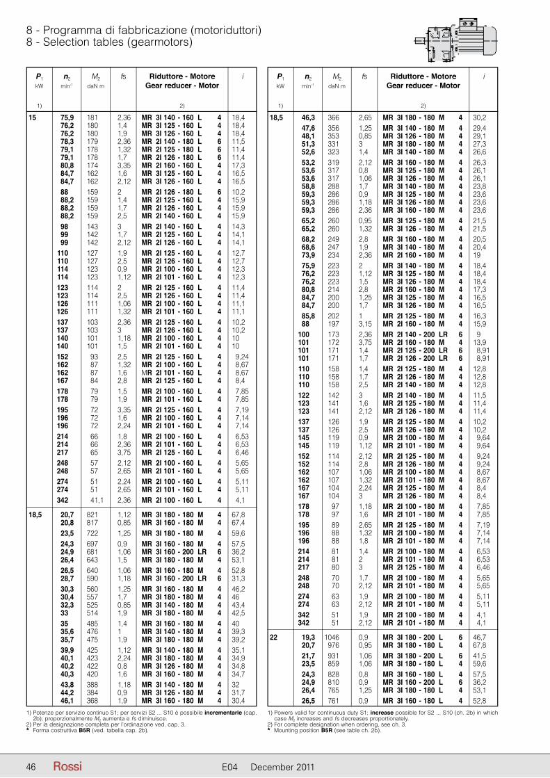
46 E04 December 2011
8 - Programma di fabbricazione (motoriduttori)8 - Selection tables (gearmotors)
P1 n2 M2 fs Riduttore - Motore i kW min-1 daN m Gear reducer - Motor
1) 2)
1) Potenze per servizio continuo S1; per servizi S2 ... S10 è possibile incrementarle (cap. 2b); proporzionalmente M2 aumenta e fs diminuisce.
2) Per la designazione completa per l’ordinazione ved. cap. 3.* Forma costruttiva B5R (ved. tabella cap. 2b).
15 75,9 181 2,36 MR 3I 140 - 160 L 4 18,4 76,2 180 1,4 MR 3I 125 - 160 L 4 18,4 76,2 180 1,9 MR 3I 126 - 160 L 4 18,4 78,3 179 2,36 MR 2I 140 - 180 L 6 11,5 79,1 178 1,32 MR 2I 125 - 180 L 6 11,4 79,1 178 1,7 MR 2I 126 - 180 L 6 11,4 80,8 174 3,35 MR 2I 160 - 160 L 4 17,3 84,7 162 1,6 MR 3I 125 - 160 L 4 16,5 84,7 162 2,12 MR 3I 126 - 160 L 4 16,5 88 159 2 MR 2I 126 - 180 L 6 10,2 88,2 159 1,4 MR 2I 125 - 160 L 4 15,9 88,2 159 1,7 MR 2I 126 - 160 L 4 15,9 88,2 159 2,5 MR 2I 140 - 160 L 4 15,9 98 143 3 MR 2I 140 - 160 L 4 14,3 99 142 1,7 MR 2I 125 - 160 L 4 14,1 99 142 2,12 MR 2I 126 - 160 L 4 14,1 110 127 1,9 MR 2I 125 - 160 L 4 12,7 110 127 2,5 MR 2I 126 - 160 L 4 12,7 114 123 0,9 MR 2I 100 - 160 L 4 12,3 114 123 1,12 MR 2I 101 - 160 L 4 12,3 123 114 2 MR 2I 125 - 160 L 4 11,4 123 114 2,5 MR 2I 126 - 160 L 4 11,4 126 111 1,06 MR 2I 100 - 160 L 4 11,1 126 111 1,32 MR 2I 101 - 160 L 4 11,1 137 103 2,36 MR 2I 125 - 160 L 4 10,2 137 103 3 MR 2I 126 - 160 L 4 10,2 140 101 1,18 MR 2I 100 - 160 L 4 10 140 101 1,5 MR 2I 101 - 160 L 4 10 152 93 2,5 MR 2I 125 - 160 L 4 9,24 162 87 1,32 MR 2I 100 - 160 L 4 8,67 162 87 1,6 MR 2I 101 - 160 L 4 8,67 167 84 2,8 MR 2I 125 - 160 L 4 8,4 178 79 1,5 MR 2I 100 - 160 L 4 7,85 178 79 1,9 MR 2I 101 - 160 L 4 7,85 195 72 3,35 MR 2I 125 - 160 L 4 7,19 196 72 1,6 MR 2I 100 - 160 L 4 7,14 196 72 2,24 MR 2I 101 - 160 L 4 7,14 214 66 1,8 MR 2I 100 - 160 L 4 6,53 214 66 2,36 MR 2I 101 - 160 L 4 6,53 217 65 3,75 MR 2I 125 - 160 L 4 6,46 248 57 2,12 MR 2I 100 - 160 L 4 5,65 248 57 2,65 MR 2I 101 - 160 L 4 5,65 274 51 2,24 MR 2I 100 - 160 L 4 5,11 274 51 2,65 MR 2I 101 - 160 L 4 5,11 342 41,1 2,36 MR 2I 100 - 160 L 4 4,1
18,5 20,7 821 1,12 MR 3I 180 - 180 M 4 67,8 20,8 817 0,85 MR 3I 160 - 180 M 4 67,4 23,5 722 1,25 MR 3I 180 - 180 M 4 59,6 24,3 697 0,9 MR 3I 160 - 180 M 4 57,5 24,9 681 1,06 MR 3I 160 - 200 LR 6 36,2 26,4 643 1,5 MR 3I 180 - 180 M 4 53,1 26,5 640 1,06 MR 3I 160 - 180 M 4 52,8 28,7 590 1,18 MR 3I 160 - 200 LR 6 31,3 30,3 560 1,25 MR 3I 160 - 180 M 4 46,2 30,4 557 1,7 MR 3I 180 - 180 M 4 46 32,3 525 0,85 MR 3I 140 - 180 M 4 43,4 33 514 1,9 MR 3I 180 - 180 M 4 42,5 35 485 1,4 MR 3I 160 - 180 M 4 40 35,6 476 1 MR 3I 140 - 180 M 4 39,3 35,7 475 1,9 MR 3I 180 - 180 M 4 39,2 39,9 425 1,12 MR 3I 140 - 180 M 4 35,1 40,1 423 2,24 MR 3I 180 - 180 M 4 34,9 40,2 422 0,8 MR 3I 126 - 180 M 4 34,8 40,3 420 1,6 MR 3I 160 - 180 M 4 34,7 43,8 388 1,18 MR 3I 140 - 180 M 4 32 44,2 384 0,9 MR 3I 126 - 180 M 4 31,7 46,1 368 1,9 MR 3I 160 - 180 M 4 30,4
P1 n2 M2 fs Riduttore - Motore i kW min-1 daN m Gear reducer - Motor
1) 2)
1) Powers valid for continuous duty S1; increase possible for S2 ... S10 (ch. 2b) in which case M2 increases and fs decreases proportionately.
2) For complete designation when ordering, see ch. 3.* Mounting position B5R (see table ch. 2b).
18,5 46,3 366 2,65 MR 3I 180 - 180 M 4 30,2 47,6 356 1,25 MR 3I 140 - 180 M 4 29,4 48,1 353 0,85 MR 3I 126 - 180 M 4 29,1 51,3 331 3 MR 3I 180 - 180 M 4 27,3 52,6 323 1,4 MR 3I 140 - 180 M 4 26,6 53,2 319 2,12 MR 3I 160 - 180 M 4 26,3 53,6 317 0,8 MR 3I 125 - 180 M 4 26,1 53,6 317 1,06 MR 3I 126 - 180 M 4 26,1 58,8 288 1,7 MR 3I 140 - 180 M 4 23,8 59,3 286 0,9 MR 3I 125 - 180 M 4 23,6 59,3 286 1,18 MR 3I 126 - 180 M 4 23,6 59,3 286 2,36 MR 3I 160 - 180 M 4 23,6 65,2 260 0,95 MR 3I 125 - 180 M 4 21,5 65,2 260 1,32 MR 3I 126 - 180 M 4 21,5 68,2 249 2,8 MR 3I 160 - 180 M 4 20,5 68,6 247 1,9 MR 3I 140 - 180 M 4 20,4 73,9 234 2,36 MR 2I 160 - 180 M 4 19 75,9 223 2 MR 3I 140 - 180 M 4 18,4 76,2 223 1,12 MR 3I 125 - 180 M 4 18,4 76,2 223 1,5 MR 3I 126 - 180 M 4 18,4 80,8 214 2,8 MR 2I 160 - 180 M 4 17,3 84,7 200 1,25 MR 3I 125 - 180 M 4 16,5 84,7 200 1,7 MR 3I 126 - 180 M 4 16,5 85,8 202 1 MR 2I 125 - 180 M 4 16,3 88 197 3,15 MR 2I 160 - 180 M 4 15,9 100 173 2,36 MR 2I 140 - 200 LR 6 9 101 172 3,75 MR 2I 160 - 180 M 4 13,9 101 171 1,4 MR 2I 125 - 200 LR 6 8,91 101 171 1,7 MR 2I 126 - 200 LR 6 8,91 110 158 1,4 MR 2I 125 - 180 M 4 12,8 110 158 1,7 MR 2I 126 - 180 M 4 12,8 110 158 2,5 MR 2I 140 - 180 M 4 12,8 122 142 3 MR 2I 140 - 180 M 4 11,5 123 141 1,6 MR 2I 125 - 180 M 4 11,4 123 141 2,12 MR 2I 126 - 180 M 4 11,4 137 126 1,9 MR 2I 125 - 180 M 4 10,2 137 126 2,5 MR 2I 126 - 180 M 4 10,2 145 119 0,9 MR 2I 100 - 180 M 4 9,64 145 119 1,12 MR 2I 101 - 180 M 4 9,64 152 114 2,12 MR 2I 125 - 180 M 4 9,24 152 114 2,8 MR 2I 126 - 180 M 4 9,24 162 107 1,06 MR 2I 100 - 180 M 4 8,67 162 107 1,32 MR 2I 101 - 180 M 4 8,67 167 104 2,24 MR 2I 125 - 180 M 4 8,4 167 104 3 MR 2I 126 - 180 M 4 8,4 178 97 1,18 MR 2I 100 - 180 M 4 7,85 178 97 1,6 MR 2I 101 - 180 M 4 7,85 195 89 2,65 MR 2I 125 - 180 M 4 7,19 196 88 1,32 MR 2I 100 - 180 M 4 7,14 196 88 1,8 MR 2I 101 - 180 M 4 7,14 214 81 1,4 MR 2I 100 - 180 M 4 6,53 214 81 2 MR 2I 101 - 180 M 4 6,53 217 80 3 MR 2I 125 - 180 M 4 6,46 248 70 1,7 MR 2I 100 - 180 M 4 5,65 248 70 2,12 MR 2I 101 - 180 M 4 5,65 274 63 1,9 MR 2I 100 - 180 M 4 5,11 274 63 2,12 MR 2I 101 - 180 M 4 5,11 342 51 1,9 MR 2I 100 - 180 M 4 4,1 342 51 2,12 MR 2I 101 - 180 M 4 4,1
22 19,3 1046 0,9 MR 3I 180 - 200 L 6 46,7 20,7 976 0,95 MR 3I 180 - 180 L 4 67,8 21,7 931 1,06 MR 3I 180 - 200 L 6 41,5 23,5 859 1,06 MR 3I 180 - 180 L 4 59,6 24,3 828 0,8 MR 3I 160 - 180 L 4 57,5 24,9 810 0,9 MR 3I 160 - 200 L 6 36,2 26,4 765 1,25 MR 3I 180 - 180 L 4 53,1 26,5 761 0,9 MR 3I 160 - 180 L 4 52,8

4747E04 December 2011
8 - Programma di fabbricazione (motoriduttori)8 - Selection tables (gearmotors)
P1 n2 M2 fs Riduttore - Motore i kW min-1 daN m Gear reducer - Motor
1) 2)
1) Potenze per servizio continuo S1; per servizi S2 ... S10 è possibile incrementarle (cap. 2b); proporzionalmente M2 aumenta e fs diminuisce.
2) Per la designazione completa per l’ordinazione ved. cap. 3.** Forma costruttiva B5R (ved. tabella cap. 2b).** Per temperatura ambiente � 30 °C interpellarci per la verifica della potenza termica.
22 27,1 745 1,32 MR 3I 180 - 200 L 6 33,2 28,7 702 1 MR 3I 160 - 200 L 6 31,3 30,3 666 1,06 MR 3I 160 - 180 L 4 46,2 30,4 663 1,4 MR 3I 180 - 180 L 4 46 33 612 1,6 MR 3I 180 - 180 L 4 42,5 35 577 1,18 MR 3I 160 - 180 L 4 40 35,6 566 0,85 MR 3I 140 - 180 L 4 39,3 35,7 565 1,6 MR 3I 180 - 180 L 4 39,2 39,9 506 0,95 MR 3I 140 - 180 L 4 35,1 40,1 502 1,9 MR 3I 180 - 180 L 4 34,9 40,3 500 1,32 MR 3I 160 - 180 L 4 34,7 43,8 461 1 MR 3I 140 - 180 L 4 32 46,1 437 1,6 MR 3I 160 - 180 L 4 30,4 46,3 435 2,24 MR 3I 180 - 180 L 4 30,2 47,6 424 1,06 MR 3I 140 - 180 L 4 29,4 51,3 393 2,5 MR 3I 180 - 180 L 4 27,3 52,6 384 1,18 MR 3I 140 - 180 L 4 26,6 53,2 379 1,8 MR 3I 160 - 180 L 4 26,3 53,6 376 0,85 MR 3I 126 - 180 L 4 26,1 55,9 368 2,12 MR 2I 180 - 200 L 6 16,1 57,6 357 1,6 MR 2I 160 - 200 L 6 15,6 58,8 343 1,4 MR 3I 140 - 180 L 4 23,8 58,8 343 2,65 MR 3I 180 - 180 L 4 23,8 59,3 340 1 MR 3I 126 - 180 L 4 23,6 59,3 340 2 MR 3I 160 - 180 L 4 23,6 60,8 339 2,5 MR 2I 180 - 200 L 6 14,8 63 327 1,9 MR 2I 160 - 200 L 6 14,3 65,2 309 0,8 MR 3I 125 - 180 L 4 21,5 65,2 309 1,12 MR 3I 126 - 180 L 4 21,5 68,2 296 2,36 MR 3I 160 - 180 L 4 20,5 68,6 294 1,6 MR 3I 140 - 180 L 4 20,4 70,4 292 0,8 MR 2I 125 - 200 L 6 12,8 70,4 292 0,95 MR 2I 126 - 200 L 6 12,8 70,4 292 1,32 MR 2I 140 - 200 L 6 12,8 71,7 287 2,8 MR 2I 180 - 180 L 4 19,5 73,9 279 2 MR 2I 160 - 180 L 4 19 75,9 266 1,6 MR 3I 140 - 180 L 4 18,4 76,2 265 0,95 MR 3I 125 - 180 L 4 18,4 76,2 265 1,25 MR 3I 126 - 180 L 4 18,4 77,9 264 3,15 MR 2I 180 - 180 L 4 18 80,8 255 2,36 MR 2I 160 - 180 L 4 17,3 84,7 238 1,06 MR 3I 125 - 180 L 4 16,5 84,7 238 1,4 MR 3I 126 - 180 L 4 16,5 85,8 240 0,85 MR 2I 125 - 180 L 4 16,3 86,4 238 1,9 MR 2I 140 - 200 L 6 10,4 88 234 2,65 MR 2I 160 - 180 L 4 15,9 88 234 1,06 MR 2I 125 - 200 L 6 10,2 88 234 1,32 MR 2I 126 - 200 L 6 10,2 100 206 2 MR 2I 140 - 200 L 6 9 101 205 3,15 MR 2I 160 - 180 L 4 13,9 101 204 1,12 MR 2I 125 - 200 L 6 8,91 101 204 1,4 MR 2I 126 - 200 L 6 8,91 110 188 1,18 MR 2I 125 - 180 L 4 12,8 110 188 1,4 MR 2I 126 - 180 L 4 12,8 110 188 2 MR 2I 140 - 180 L 4 12,8 110 187 2,36 MR 2I 140 - 200 L 6 8,15 113 183 1,32 MR 2I 125 - 200 L 6 8 113 183 1,7 MR 2I 126 - 200 L 6 8 116 177 3,75 MR 2I 160 - 180 L 4 12,1 122 169 2,5 MR 2I 140 - 180 L 4 11,5 123 167 1,4 MR 2I 125 - 180 L 4 11,4 123 167 1,7 MR 2I 126 - 180 L 4 11,4 124 165 2 MR 2I 126 - 200 L 6 7,23 134 153 2,8 MR 2I 140 - 180 L 4 10,4 137 150 1,6 MR 2I 125 - 180 L 4 10,2 137 150 2 MR 2I 126 - 180 L 4 10,2 152 136 1,8 MR 2I 125 - 180 L 4 9,24 152 136 2,36 MR 2I 126 - 180 L 4 9,24 167 123 1,9 MR 2I 125 - 180 L 4 8,4 167 123 2,65 MR 2I 126 - 180 L 4 8,4
P1 n2 M2 fs Riduttore - Motore i kW min-1 daN m Gear reducer - Motor
1) 2)
1) Powers valid for continuous duty S1; increase possible for S2 ... S10 (ch. 2b) in which case M2 increases and fs decreases proportionately.
2) For complete designation when ordering, see ch. 3.** Mounting position B5R (see table ch. 2b).** In case of ambient temperature � 30 °C consult us for thermal power verification.
22 195 106 2,24 MR 2I 125 - 180 L 4 7,19 195 106 3 MR 2I 126 - 180 L 4 7,19 217 95 2,5 MR 2I 125 - 180 L 4 6,46 274 75 2,65 MR 2I 125 - 180 L 4 5,11
30 30 917 1 MR 3I 180 - 200 L 4 46,7 33,7 816 1,18 MR 3I 180 - 200 L 4 41,5 38,7 710 0,95 MR 3I 160 - 200 L 4 36,2 38,9 707 1,32 MR 3I 180 - 200 L 4 36 42,1 653 1,4 MR 3I 180 - 200 L 4 33,2 44,7 616 1,12 MR 3I 160 - 200 L 4 31,3 45,7 602 1,5 MR 3I 180 - 200 L 4 30,7 51,3 536 1,7 MR 3I 180 - 200 L 4 27,3 51,5 534 1,25 MR 3I 160 - 200 L 4 27,2 * 52,6 523 0,9 MR 3I 140 - 200 L * 4 26,6 * 58,8 468 1 MR 3I 140 - 200 L * 4 23,8 58,9 467 1,4 MR 3I 160 - 200 L 4 23,8 59,2 465 2 MR 3I 180 - 200 L 4 23,7 65,6 420 2,24 MR 3I 180 - 200 L 4 21,4 68 405 1,7 MR 3I 160 - 200 L 4 20,6 * 68,6 401 1,18 MR 3I 140 - 200 L * 4 20,4 75,2 366 2,36 MR 3I 180 - 200 L 4 18,6 75,7 363 1,9 MR 3I 160 - 200 L 4 18,5 * 75,9 362 1,18 MR 3I 140 - 200 L * 4 18,4 87 323 2,36 MR 2I 180 - 200 L 4 16,1 87,2 316 2,12 MR 3I 160 - 200 L 4 16,1 89,6 313 1,8 MR 2I 160 - 200 L 4 15,6 94,5 297 2,8 MR 2I 180 - 200 L 4 14,8 98 286 2 MR 2I 160 - 200 L 4 14,3 106 264 3,35 MR 2I 180 - 200 L 4 13,2 107 263 2,36 MR 2I 160 - 200 L 4 13,1 110 256 0,85 MR 2I 125 - 200 L 4 12,8 110 256 1,06 MR 2I 126 - 200 L 4 12,8 110 256 1,5 MR 2I 140 - 200 L 4 12,8 122 231 1,8 MR 2I 140 - 200 L 4 11,5 122 230 2,8 MR 2I 160 - 200 L 4 11,5 123 228 1 MR 2I 125 - 200 L 4 11,4 123 228 1,25 MR 2I 126 - 200 L 4 11,4 134 209 2,12 MR 2I 140 - 200 L 4 10,4 137 205 1,18 MR 2I 125 - 200 L 4 10,2 137 205 1,5 MR 2I 126 - 200 L 4 10,2 141 199 3,15 MR 2I 160 - 200 L 4 9,94 156 180 2,24 MR 2I 140 - 200 L 4 9 157 179 1,25 MR 2I 125 - 200 L 4 8,91 157 179 1,6 MR 2I 126 - 200 L 4 8,91 172 164 2,65 MR 2I 140 - 200 L 4 8,15 175 160 1,5 MR 2I 125 - 200 L 4 8 175 160 1,9 MR 2I 126 - 200 L 4 8 192 146 2,65 MR 2I 140 - 200 L 4 7,29 194 145 1,6 MR 2I 125 - 200 L 4 7,23 194 145 2,12 MR 2I 126 - 200 L 4 7,23 213 132 1,8 MR 2I 125 - 200 L 4 6,57 213 132 2,36 MR 2I 126 - 200 L 4 6,57 224 125 2,65 MR 2I 140 - 200 L 4 6,25 249 113 2,12 MR 2I 125 - 200 L 4 5,63 249 113 2,65 MR 2I 126 - 200 L 4 5,63 277 101 2,36 MR 2I 125 - 200 L 4 5,06 277 101 2,65 MR 2I 126 - 200 L 4 5,06 350 80 2,5 MR 2I 125 - 200 L 4 4
37 30 1131 0,8 MR 3I 180 - 225 S 4 46,7 33,7 1006 0,95 MR 3I 180 - 225 S 4 41,5 38,7 876 0,8 MR 3I 160 - 225 S 4 36,2 38,9 872 1,06 MR 3I 180 - 225 S 4 36 42,1 805 1,18 MR 3I 180 - 225 S 4 33,2 44,7 759 0,9 MR 3I 160 - 225 S 4 31,3 45,7 743 1,18 MR 3I 180 - 225 S 4 30,7

48 E04 December 2011
8 - Programma di fabbricazione (motoriduttori)8 - Selection tables (gearmotors)
P1 n2 M2 fs Riduttore - Motore i kW min-1 daN m Gear reducer - Motor
1) 2)
37 51,3 661 1,4 MR 3I 180 - 225 S 4 27,3 51,5 658 1 MR 3I 160 - 225 S 4 27,2 58,9 576 1,18 MR 3I 160 - 225 S 4 23,8 59,2 573 1,7 MR 3I 180 - 225 S 4 23,7 65,6 517 1,8 MR 3I 180 - 225 S 4 21,4 68 499 1,32 MR 3I 160 - 225 S 4 20,6 75,2 451 1,9 MR 3I 180 - 225 S 4 18,6 75,7 448 1,5 MR 3I 160 - 225 S 4 18,5 87,2 389 1,7 MR 3I 160 - 225 S 4 16,1 106 325 2,36 MR 2I 180 - 225 S 4 13,1 110 316 1,7 MR 2I 160 - 225 S 4 12,8 116 299 2,8 MR 2I 180 - 225 S 4 12,1 120 289 2 MR 2I 160 - 225 S 4 11,7 130 266 3,15 MR 2I 180 - 225 S 4 10,8 131 265 2,36 MR 2I 160 - 225 S 4 10,7 * 140 247 1,5 MR 2I 140 - 225 S 4 10 149 232 2,8 MR 2I 160 - 225 S 4 9,37 150 231 3,15 MR 2I 180 - 225 S 4 9,33 * 156 223 1,8 MR 2I 140 - 225 S 4 9 * 172 202 2,12 MR 2I 140 - 225 S 4 8,15 172 201 3,15 MR 2I 160 - 225 S 4 8,12 * 192 180 2,12 MR 2I 140 - 225 S 4 7,29 * 224 155 2,12 MR 2I 140 - 225 S 4 6,25 * 248 140 2,12 MR 2I 140 - 225 S 4 5,65
45 * 33,7 1224 0,8 MR 3I 180 - 225 M 4 41,5 * 38,9 1061 0,9 MR 3I 180 - 225 M 4 36 * 42,1 979 0,95 MR 3I 180 - 225 M 4 33,2 * 45,7 904 0,95 MR 3I 180 - 225 M 4 30,7 * 51,3 804 1,18 MR 3I 180 - 225 M 4 27,3 * 51,5 800 0,8 MR 3I 160 - 225 M 4 27,2 * 58,9 700 0,95 MR 3I 160 - 225 M 4 23,8 * 59,2 697 1,4 MR 3I 180 - 225 M 4 23,7 * 65,6 629 1,5 MR 3I 180 - 225 M 4 21,4 * 68 607 1,12 MR 3I 160 - 225 M 4 20,6 * 75,2 549 1,6 MR 3I 180 - 225 M 4 18,6 * 75,7 545 1,25 MR 3I 160 - 225 M 4 18,5 * 87,2 473 1,4 MR 3I 160 - 225 M 4 16,1 106 396 2 MR 2I 180 - 225 M 4 13,1 110 384 1,4 MR 2I 160 - 225 M 4 12,8 116 364 2,24 MR 2I 180 - 225 M 4 12,1 120 351 1,7 MR 2I 160 - 225 M 4 11,7 130 324 2,65 MR 2I 180 - 225 M 4 10,8
P1 n2 M2 fs Riduttore - Motore i kW min-1 daN m Gear reducer - Motor
1) 2)
45 131 322 1,9 MR 2I 160 - 225 M 4 10,7
* 140 301 1,25 MR 2I 140 - 225 M 4 10
149 282 2,24 MR 2I 160 - 225 M 4 9,37
150 281 2,65 MR 2I 180 - 225 M 4 9,33 * 156 271 1,5 MR 2I 140 - 225 M 4 9
* 172 245 1,7 MR 2I 140 - 225 M 4 8,15 172 244 2,65 MR 2I 160 - 225 M 4 8,12
192 219 2,65 MR 2I 160 - 225 M 4 7,29 * 192 219 1,7 MR 2I 140 - 225 M 4 7,29
221 191 2,65 MR 2I 160 - 225 M 4 6,34 * 224 188 1,7 MR 2I 140 - 225 M 4 6,25
* 248 170 1,7 MR 2I 140 - 225 M 4 5,65
55 ** 42,1 1197 0,8 MR 3I 180 - 250 M * 4 33,2 ** 45,7 1105 0,8 MR 3I 180 - 250 M * 4 30,7
** 51,3 983 0,95 MR 3I 180 - 250 M * 4 27,3
** 59,2 852 1,12 MR 3I 180 - 250 M * 4 23,7
** 65,6 769 1,25 MR 3I 180 - 250 M * 4 21,4
** 75,2 671 1,32 MR 3I 180 - 250 M * 4 18,6
106 483 1,6 MR 2I 180 - 250 M 4 13,1 * 110 469 1,18 MR 2I 160 - 250 M 4 12,8 116 445 1,9 MR 2I 180 - 250 M 4 12,1
* 120 429 1,32 MR 2I 160 - 250 M 4 11,7 130 396 2,12 MR 2I 180 - 250 M 4 10,8 * 131 394 1,6 MR 2I 160 - 250 M 4 10,7
* 149 345 1,9 MR 2I 160 - 250 M 4 9,37
150 343 2,12 MR 2I 180 - 250 M 4 9,33 166 310 2,12 MR 2I 180 - 250 M 4 8,43
* 172 299 2,12 MR 2I 160 - 250 M 4 8,12
191 270 2,12 MR 2I 180 - 250 M 4 7,35 * 192 268 2,12 MR 2I 160 - 250 M 4 7,29
* 221 233 2,12 MR 2I 160 - 250 M 4 6,34
75 ** 136 516 1,5 MR 2I 180 - 280 S 4 10,3 ** 148 475 1,7 MR 2I 180 - 280 S 4 9,48
** 166 423 1,7 MR 2I 180 - 280 S 4 8,44
** 191 367 1,7 MR 2I 180 - 280 S 4 7,31
** 212 331 1,7 MR 2I 180 - 280 S 4 6,6
** 243 289 1,7 MR 2I 180 - 280 S 4 5,76 1) Potenze per servizio continuo S1; per servizi S2 ... S10 è possibile incrementarle (cap.
2b); proporzionalmente M2 aumenta e fs diminuisce. 2) Per la designazione completa per l’ordinazione ved. cap. 3.** Forma costruttiva B5R (ved. tabella cap. 2b).** Per temperatura ambiente � 30 °C interpellarci per la verifica della potenza termica.** Interpellarci per la verifica della potenza termica.
1) Powers valid for continuous duty S1; increase possible for S2 ... S10 (ch. 2b) in which case M2 increases and fs decreases proportionately.
2) For complete designation when ordering, see ch. 3.** Mounting position B5R (see table ch. 2b).** In case of ambient temperature � 30 °C consult us for thermal power verification.** Consult us for thermal power verification.

4949E04 December 2011
Pagina lasciata intenzionalmente bianca.This page is intentionally left blank.

50 E04 December 2011
9 - Esecuzioni, dimensioni, forme costrut-tive e quantità di lubrificante
9 - Designs, dimensions, mounting positions and lubrificant quantities
MR 2I, 3I 32 ... 41
PC1A
FC1A
UT.
C 2
10U
T.C
211
Esecuzione1) normaleForma costruttiva B3, B6, B7, B8, V5, V6
Esecuzione1) normaleForma costruttiva B5, V1, V3
Standard design1) Mounting position B3, B6, B7, B8, V5, V6
Standard design1) Mounting position B5, V1, V3
Forme costruttive e quantità di grasso [kg]
Salvo diversa indicazione i motoriduttori vengono forniti nelle forme costruttive normali B3 o B5 le quali, in quanto normali, non vanno indicati nella designazione.
Unless otherwise stated, geamotors are supplied in mounting positions B3 or B5 which, being standard, are omitted from the designation.
Mounting positions and grease quantities [kg] Grandezza B3, B6 V5, V6 Size B7, B8
32 0,14 0,25 40,41 0,26 0,47
B5 V1, V3
32 0,14 0,18 40,41 0,19 0,35
UT.C 217
B3 B6 B7 B8 V5 V6
B5 V1 V3
Esec
uzio
ne -
Des
ign
PC1A
FC1A
1) Per l’esecuzione propria del motore consultare cap. 3. 2) Valori validi per motore autofrenante. 3) Forma costruttiva B5A (ved. cap. 2b), motore autofrenante F0 80D non possibile. 4) Forma costruttiva B5R (ved. cap. 2b). 5) Rispettivamente quote battuta estremità d’albero e piano flangia. 6) Per la grand. 51 la quota Y1 è -8 mm. 7) Per asse motore la quota H è -15 mm, H0 +15 mm. 8) Per asse motore la quota H è -8 mm, H0 +8 mm. 9) Per asse motore la quota H è -29 mm, H0 +29 mm.10) Due fori della flangia motore sono asolati (ved. cap. 2b).
1) See ch. 3 for motor design. 2) Values valid for brake motor. 3) Mounting position B5A (see ch. 2b), brake motor F0 80D not possible. 4) Mounting position B5R (see ch. 2b). 5) Dimensions of shaft end shoulder and flange surface respectively. 6) For size 51 Y1 is -8 mm. 7) For motor shaft H is -15 mm, H0 +15 mm. 8) For motor shaft H is -8 mm, H0 +8 mm. 9) For motor shaft H is -29 mm, H0 +29 mm.10) Two of the motor flange holes are slotted (see ch. 2b).
Grandezza A B C D E F G H K L M N P Q S T U V P1 X Y Y1 W W1 Massa Size Ø Ø h11 Ø Ø Ø Ø Ø Ø ≈ ≈ ≈ ≈ Mass ridutt. motore h6 ≈ kg red. motor B5 Z 2) 2) 2) 32 634) 115 53 20 16 30 9,5 98-885) 75 9,5 10 115 95 140 3,5 10 139 77 48 140 122 714) 73 140 140 40 634) 132 63 19 19 40 9,5 113 90 9,5 12 130 110 160 3,5 10 156 92 56 140 122 714) 87 160 140 803)) 160 160 41 631) 132 63 34 24 36 9,5 128-1135) 90 9,5 12 130 110 160 3,5 10 156 92 56 140 122 711) 87 160 140 803)) 160 160
185 229 313 357 101 176 8 10 225 288 353 416 112 187 11 14 185 229 338 382 101 191 11 13 211 275 364 428 112 202 14 17 245 325 398 478 122 212 17 22 185 229 349 393 101 191 11 13 211 275 375 439 112 202 14 17 245 325 409 489 122 212 17 22
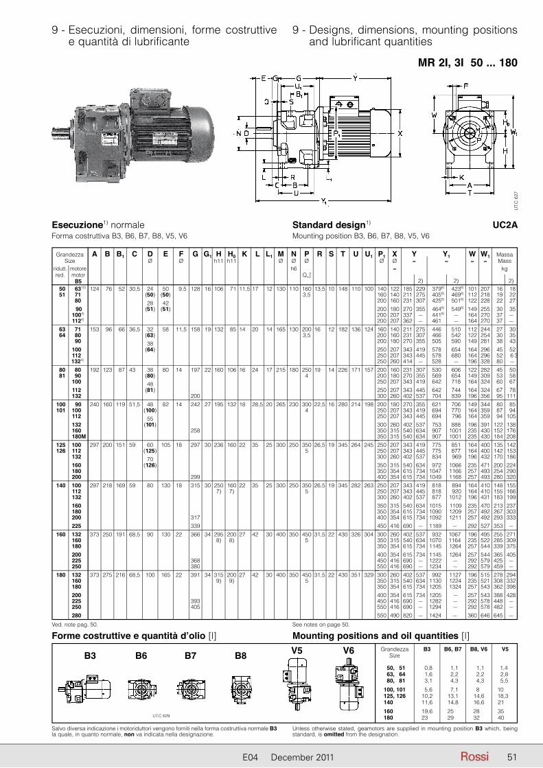
9 - Esecuzioni, dimensioni, forme costruttive e quantità di lubrificante
9 - Designs, dimensions, mounting positions and lubrificant quantities
5151E04 December 2011
MR 2I, 3I 50 ... 180
UT.
C 6
27
UC2AEsecuzione1) normaleForma costruttiva B3, B6, B7, B8, V5, V6
Standard design1) Mounting position B3, B6, B7, B8, V5, V6
Ved. note pag. 50.
Grandezza A B B1 C D E F G G1 H H0 K L L1 M N P R S T U U1 Size Ø Ø h11 h11 Ø Ø Ø ridutt. motore h6 red. motor Q+2
B5
0
50 6310) 124 76 52 30,5 24 50 9,5 128 16 106 71 11,5 17,5 12 130 110 160 13,5 10 148 110 100 51 7110) (50) (50) 3,5 8010) 9010)
28 42
1004)0 (51) (51)
1124)
63 7110) 153 96 66 36,5 32 58 11,5 158 19 132 85 14,5 20,5 14 165 130 200 16,5 12 182 136 124 64 8010) (63) 3,5 9010) 10010)
38
1124)0 (64)
1324))0
80 8010) 192 123 87 43,5 38 80 14,5 197 22 160 106 16,5 24,5 17 215 180 250 19,5 14 226 171 157 81 9010) (80) 4 10010) 11210)
48
1324)0 (81)
200 100 9010)) 240 160 119 51,5 48 82 14,5 242 27 195 132 18,5 28,5 20 265 230 300 22,5 16 280 214 198 101 10010) (100) 4 11210) 13210)
55
1604)0 (101)
258 180M 125 10010)) 297 200 151 59,5 60 105 18,5 297 30 236 160 22,5 35,5 25 300 250 350 26,5 19 345 264 245 126 11210) (125) 5 13210) 16010)
70
1804)0 (126)
2004)0 299 140 10010)) 297 218 169 59,5 80 130 18,5 315 30 250 160 22,5 35,5 25 300 250 350 26,5 19 345 282 263 11210) 7) 7) 5 13210) 16010)
1804)0
2004)0 317 2254)0 339 160 13210)) 373 250 191 68,5 90 130 22,5 366 34 295 200 27,5 42,5 30 400 350 450 31,5 22 430 326 304 16010) 8) 8) 5 18010) 20010)
2254)0
368 2504)0 380 180 13210)) 373 275 216 68,5 100 165 22,5 391 34 315 200 27,5 42,5 30 400 350 450 31,5 22 430 351 329 16010) 9) 9) 5 18010) 20010)
2254)0
393 2504)0 405 2804)0
P1 X Y Y1 W W1 Massa Ø Ø ≈ ≈ ≈ ≈ Mass ≈ kg
2) 2) 2) 140 122 185 229 3796) 4236) 101 207 16 18 160 140 211 275 4056) 4696) 112 218 19 22 200 160 231 307 4256) 5016) 122 228 22 27 200 180 270 355 4646) 5496) 149 255 30 35 200 207 337 – 4416) – 164 270 37 – 200 207 362 – 4616) – 164 270 37 – 160 140 211 275 4466) 5106) 112 244 27 30 200 160 231 307 4666) 5426) 122 254 30 35 200 180 270 355 5056) 5906) 149 281 38 43 250 207 343 419 5786) 6546) 164 296 45 52 250 207 343 445 5786) 680 164 296 52 6 3 250 260 414 – 5286) – 196 328 80 – 200 160 231 307 5306) 6066) 122 282 45 50 200 180 270 355 5696) 6546) 149 309 53 58 250 207 343 419 6426) 7186) 164 324 60 67 250 207 343 445 6426) 7446) 164 324 67 78 300 260 402 537 7046) 839 196 356 95 111 200 180 270 355 6216) 7066) 149 344 80 85 250 207 343 419 6946) 7706) 164 359 87 94 250 207 343 445 6946) 7966 164 359 94 105 300 260 402 537 7536) 8886) 196 391 122 138 350 315 540 634 9076) 10016 235 430 152 176 350 315 540 634 9076) 10016 235 430 184 208 250 207 343 419 7756) 8516) 164 400 135 142 250 207 343 445 7756) 8776) 164 400 142 153 300 260 402 537 8346) 9696 196 432 170 186 350 315 540 634 9726) 10666 235 471 200 224 350 354 615 734 10476) 11666 257 493 254 290 400 354 615 734 10496) 11686 257 493 280 320 250 207 343 419 8186) 8946 164 410 148 155 250 207 343 445 8186) 9206 164 410 155 166 300 260 402 537 8776) 10126 196 431 183 199 350 315 540 634 10156) 11096) 235 470 213 237 350 354 615 734 10906) 12096 257 492 267 303 400 354 615 734 10926) 12116 257 492 293 333 450 416 690 – 11896) –6) 292 527 353 – 300 260 402 537 9326) 10676) 196 495 255 271 350 315 540 634 10706) 11646) 235 522 285 309 350 354 615 734 11456) 12646 257 544 339 375 400 354 615 734 11456) 12646 257 544 365 405 450 416 690 – 12226) –6 292 579 425 – 550 416 690 – 12346) –6 292 579 459 – 300 260 402 537 9926) 11276 196 515 278 294 350 315 540 634 11306) 12246 235 521 308 332 350 354 615 734 12056) 13246 257 543 362 398 400 354 615 734 12056) –6) 257 543 388 428 450 416 690 – 12826) –6 292 578 448 – 550 416 690 – 12946) –6 292 578 482 – 550 490 820 – 14246) –6) 360 646 645 –
Salvo diversa indicazione i motoriduttori vengono forniti nella forma costruttiva normale B3la quale, in quanto normale, non va indicata nella designazione.
Forme costruttive e quantità d’olio [l] Mounting positions and oil quantities [l] Grandezza B3 B6, B7 B8, V6 V5 Size
50, 51 0,8 1,1 1,1 1,4 63, 64 1,6 2,2 2,2 2,8 80, 81 3,1 4,3 4,3 5,5
100, 101 5,6 7,1 8,1 10,4 125, 126 10,2 13,1 14,6 18,3 140, 101 11,6 14,8 16,6 21,3
160, 101 19,6 25,8 28,6 35,3 180, 101 23,6 29,8 32,6 40,3
Unless otherwise stated, geamotors are supplied in mounting position B3 which, being standard, is omitted from the designation.
UT.C 629
B3 B6 B7 B8 V5 V6
See notes on page 50.

52 E04 December 2011
10 - Gruppi riduttori e motoriduttori 10 - Combined gear reducer and gearmo-tor units
11 - Dimensioni gruppi1) 11 - Combined unit dimensions1)
Momenti torcenti nominali riduttore finale Nominal torques for final gear reducer
MR 3I ... + R 2I, 3I ...63 ... 81
100 ... 180
For initial gear reducer or gearmotor performance data see ch. 6 and 8.1) Final gearmotor has a 160 mm motor mounting flange (see dimension P0 ch. 11).2) Gear reducer in design «Oversized B5 flange» (see ch. 16); moreover, size 63 has the
low speed shaft reduced to 28 mm: «Oversized B5 flange - Ø 28».3) Provided that fs is always � 0,8, it can be reduced by 1,06 for n2 = 2,8 � 0,71 min-1, by
1,12 for n2 � 0,71 min-1.
Prestazioni del riduttore o motoriduttore iniziale: cap. 6 e 8.1) Il motoriduttore finale ha una flangia di attacco (quota P0 cap. 11) di 160 mm.2) Riduttore in esecuzione «Flangia B5 maggiorata» (ved. cap. 16); la grandezza 63 ha
inoltre l’albero lento ridotto a 28 mm: «Flangia B5 maggiorata - Ø 28».3) Purché risulti sempre � 0,8, fs richiesto può essere ridotto di 1,06 per n2 = 2,8 � 0,71
min-1, di 1,12 per n2 � 0,71 min-1.
1) For design, mounting position and lubricant quantity of single gear reducers, see ch. 7 and 9.
Notes of page 53.1) For high speed shaft or motor shaft H is -15 mm, H0 +15 mm.2) For high speed shaft or motor shaft H is -8 mm, H0 +8 mm.3) For high speed shaft or motor shaft H is -29 mm, H0 +29 mm.4) Values valid for brake motor.
1) Per esecuzione, forma costruttiva e quantità di lubrificante dei singoli riduttori ved. cap. 7 e 9.
Note di pag. 53.1) Per asse veloce o asse motore la quota H è -15 mm, H0 +15 mm.2) Per asse veloce o asse motore la quota H è -8 mm, H0 +8 mm.3) Per asse veloce o asse motore la quota H è -29 mm, H0 +29 mm.4) Valori validi per motore autofrenante.
MN2 [daN m] Riduttore finale Riduttore o motoriduttore iniziale
perfor n2 � 11,2 min-1 3)
�
finalefinal
i
finalefinal Final gear reducer + Initial gear reducer or gearmotor
33,5 0,94 30 MR 3I 63-80B 4 ... B5A/46,71) + R 2I o / or MR 2I, 3I 40
45 30 MR 3I 64-80B 4 ... B5A/46,71) + R 2I o / or MR 2I, 3I 40
67 32,8 MR 3I 80-80C 4 ... B5A/42,71) + R 2I o / or MR 2I, 3I 40
90 49,8 MR 3I 81-80C 4 ... B5A/28,11) + R 2I o / or MR 2I, 3I 40
132 32 MR 3I 100-90LC 4 ... B5/43,8 + R 2I, 3I o / or MR 2I, 3I 502)
180 53,1 MR 3I 101-90LC 4 ... B5/26,4 + R 2I, 3I o / or MR 2I, 3I 502)
265 34,1 MR 3I 125-112M 4 ... B5/41,1 + R 2I, 3I o / or MR 2I, 3I 632)
355 50,2 MR 3I 126-112M 4 ... B5/27,9 + R 2I, 3I o / or MR 2I, 3I 632)
500 55,7 MR 3I 140-112MC 4 ... B5/25,1 + R 2I, 3I o / or MR 2I, 3I 632)
710 49,7 MR 3I 160-132MB 4 ... B5/28,2 + R 2I, 3I o / or MR 2I, 3I 802)
1 000 57,1 MR 3I 180-132MB 4 ... B5/24,5 + R 2I, 3I o / or MR 2I, 3I 802)

5353E04 December 2011
See notes on page 52.
11 - Dimensioni gruppi 11 - Combined unit dimensions
100 ... 180
Grandezza riduttore A B C c D E d Y1 d Y1 d Y1 d Y1 F G1 H K L M N P P0 P1 R S T U W1 Massa Gear reducer size Ø Ø Ø Ø Ø Ø h11 Ø Ø Ø Ø Ø Ø Mass R2I R3I h6 kg finale iniziale final initial B1 e e e e H0 L
1 Q+
02 U
1 iN � 12,5 iN � 16 iN � 80 iN � 100 h11
MR 3I 63 R 2I 40 153 96 36,5 280 32 58 11 380 11 380 – – – – 11,5 19 132 14 20 165 130 200 160 – 16 12 182 136 217 27 64 66 38 23 23 – – – – 85 14 3,5 124
MR 3I 80 R 2I 40 192 123 43 319 38 80 11 444 11 444 – – – – 14 22 160 16 24 215 180 250 160 – 19 14 226 171 266 42 81 87 48 23 23 – – – – 106 17 4 157
MR 3I 100 R 2I, 3I 50 240 160 51,5 396 48 82 14 535 14 535 11 528 11 528 14 27 195 18 28,5 265 230 300 200 140 22,5 16 280 214 327 74 101 119 55 30 30 23 23 132 20 4 198
MR 3I 125 R 2I, 3I 63 297 200 59 484 60 105 19 649 16 649 14 649 14 649 18 30 236 22 35 300 250 350 250 160 26,5 19 345 264 396 130 126 151 70 40 30 30 30 160 25 5 245
MR 3I 140 R 2I, 3I 63 297 218 59 502 80 130 11 692 16 692 14 692 14 692 18 30 2501) 22 35 300 250 350 250 160 26,5 19 345 282 410 143 169 23 30 30 30 1601) 25 5 263
MR 3I 160 R 2I, 3I 80 373 250 68,5 596 90 130 11 800 19 800 19 800 16 790 22 34 2952) 27 42 400 350 450 300 200 31,5 22 430 326 495 230 191 23 40 40 30 2002) 30 5 304
MR 3I 180 R 2I, 3I 80 373 275 68,5 621 100 165 11 800 19 860 19 860 16 850 22 34 3153) 27 42 400 350 450 300 200 31,5 22 430 351 515 253 216 23 40 40 30 2003) 30 5 329
Grandezza A B C D E F G G1 H K L M N P R S T U P0 P1 X Y Y1 W W1 Massa Size Ø Ø h11 Ø Ø Ø Ø Ø Ø Ø ≈ ≈ ≈ ≈ Mass riduttore motore h6 ≈ kg gear reducer motor finale iniziale B1 H0 L1 Q+
02 U1
final initial B5 h11 4) 4) 4)
MR 3I 63 MR 2I, 3I 40 63 153 96 36,5 32 58 11,5 271 19 132 14 20 165 130 200 16 12 182 136 160 140 122 185 229 533 577 101 233 31 33 64 71 66 (63) 85 14 3,5 124 160 140 211 275 559 623 112 244 34 37 38 (64)
MR 3I 80 MR 2I, 3I 40 63 192 123 43 38 80 14 310 22 160 16 24 215 180 250 19 14 226 171 160 140 122 185 229 597 641 101 266 46 48 81 71 87 (80) 106 17 4 157 160 140 211 275 623 687 112 272 49 52 80 B5A 48 160 160 245 325 657 737 122 282 52 57 (81)
MR 3I 100 MR 2I, 3I 50 63 240 160 51,5 48 82 14 386 27 195 18 28,5 265 230 300 22,5 16 280 214 200 140 122 185 229 680 724 101 327 78 80 101 71 119 (100) 132 20 4 198 160 140 211 275 706 770 112 327 81 84 80 55 200 160 231 307 726 802 122 327 84 89 90 (101) 200 180 270 355 765 850 149 344 92 97
MR 3I 125 MR 2I, 3I 63 71 297 200 59 60 105 18 474 30 236 22 35 300 250 350 26,5 19 345 264 250 160 140 211 275 820 884 112 396 137 140 126 80 151 (125) 160 25 5 245 200 160 231 307 839 915 122 396 140 145 90 70 200 180 270 355 878 963 149 396 148 153 100 (126) 250 207 343 419 951 1 027 164 400 155 162
MR 3I 140 MR 2I, 3I 63 71 297 218 59 80 130 18 492 30 250 22 35 300 250 350 26,5 19 345 282 250 160 140 211 275 863 927 112 410 150 153 80 169 160 25 5 263 200 160 231 307 882 958 122 410 153 158 90 1) 200 180 270 355 921 1 006 149 410 161 166 100 250 207 343 419 994 1 070 164 410 168 175 112 250 207 343 445 994 1 096 164 410 175 186
MR 3I 160 MR 2I, 3I 80 80 373 250 68,5 90 130 22 585 34 295 27 42 400 350 450 31,5 22 430 326 300 200 160 231 307 980 1 056 122 495 240 245 90 191 200 30 5 304 200 180 270 355 1 019 1 104 149 495 248 253 100 2) 250 207 343 419 1 092 1 168 164 495 255 262 112 250 207 343 445 1 092 1 194 164 495 262 273 132 588 300 260 402 537 1 154 1 289 196 495 290 306
MR 3I 180 MR 2I, 3I 80 80 373 275 68,5 100 165 22 610 37 315 27 42 400 350 450 31,5 22 430 351 300 200 160 231 307 1 040 1 116 122 515 263 268 90 216 200 30 5 329 200 180 270 355 1 079 1 164 149 515 271 276 100 3) 250 207 343 419 1 152 1 228 164 515 278 285 112 250 207 343 445 1 152 1 254 164 515 285 296 132 613 300 260 402 537 1 214 1 349 196 515 313 329
Ved. note pag. 52.
MR 3I ... + MR 2I, 3I ...

54 E04 December 2011
12 - Carichi radiali1) Fr1 [daN] sull’estremità d’albero veloce
12 - Radial loads1) Fr1 [daN] on high speed shaft end
Quando il collegamento tra motore e riduttore è realizzato con una trasmissione che genera carichi radiali sull’estremità d’albero, è ne cessario che questi siano minori o uguali a quelli indicati in tabella.Per i casi di trasmissioni più comuni, il carico radiale Fr1 è dato dalle formule seguenti:
Fr1 =
2 865 · P1
d · n1 [daN] per trasmissione a cinghia dentata
Fr1 =
4 775 · P1
d · n1 [daN] per trasmissione a cinghie trapezoidali
dove: P1 [kW] è la potenza richiesta all’entrata del riduttore, n1 [min-1] è la velocità angolare, d [m] è il diametro primitivo.
I carichi radiali ammessi in tabella valgono per carichi agenti in mezze-ria dell’estremità d’albero veloce cioè ad una distanza dalla battuta di 0,5 · e (e = lunghezza dell’estremità d’albero); se agiscono a 0,315 · e moltiplicarli per 1,25; se agiscono a 0,8 · e moltiplicarli per 0,8.
Radial loads generated on the shaft end by a drive connecting gear reducer and motor must be less than or equal to those given in the relevant table.The radial load Fr1 given by the following formula refers to most com mon drives:
Fr1 =
2 865 · P1
d · n1 [daN] for timing belt drive
Fr1 =
4 775 · P1
d · n1 [daN] for V-belt drive
where: P1 [kW] is power required at the input side of the gear redu-cer, n1 [min-1] is the speed, d [m] is the pitch diameter.
Radial loads given in the table are valid for overhung loads on centre line of high speed shaft end, i.e. operating at a distance of 0,5 · e (e = shaft end length) from the shoulder. If they operate at 0,315 · e multiply by 1,25; if they operate at 0,8 · e multiply by 0,8.
13 - Carichi radiali Fr2 [daN] o assiali Fa2 [daN] sull’estremità d’albero lento
Carichi assiali Fa2
Il valore ammissibile di Fa2 si trova nella colonna per la quale il senso di rotazione dell’albero lento (freccia bianca o freccia nera) e il sen so della forza assiale (freccia intera o freccia tratteggiata) corrispondono a quelli che si hanno sul riduttore.Quando è possibile, mettersi nelle condizioni corrispondenti alla co lonna con valori ammissibili più elevati.
Carichi radiali Fr2
Quando il collegamento tra riduttore e macchina è realizzato con una trasmissione che genera carichi radiali sull’estremità d’albero, è ne cessario che questi siano minori o uguali a quelli indicati in tabella.Normalmente il carico radiale sull’estremità d’albero lento assume valori rilevanti; infatti si tende a realizzare la trasmissione tra ridutto-re e macchina con elevato rapporto di riduzione (per economizzare sul riduttore) e con diametri piccoli (per economizzare sulla trasmis-sione o per esigenze d’ingombro).Evidentemente la durata e l’usura (che influisce negativamente an che sugli ingranaggi) dei cuscinetti e la resistenza dell’asse lento pongono dei limiti al carico radiale ammissibile.L’elevato valore che può assumere il carico radiale e l’importanza di non superare i valori ammissibili richiedono di sfruttare al massimo le possibilità del riduttore.Pertanto i carichi radiali ammessi in tabella sono in funzione: del prodotto della velocità angolare n2 [min-1] per la durata dei cuscinetti Lh [h] richiesta, del senso di rotazione, della posizione angolare � [°] del carico e del momento torcente M2 [daN m] richiesto.I carichi radiali ammessi in tabella valgono per carichi agenti in mez-zeria dell’estremità d’albero lento, cioè ad una distanza dalla battuta di 0,5 · E (E = lunghezza dell’estremità d’albero); se agiscono a 0,315 · E moltiplicarli per 1,25; se agiscono a 0,8 · E moltiplicarli per 0,8.
13 - Radial loads Fr2 [daN] or axial loads Fa2 [daN] on low speed shaft end
Axial loadsFa2
Permissible Fa2 is shown in the column where direction of rotation of low speed shaft (black or white arrow) and direction of the axial force (solid or broken arrow) correspond to those of the gear redu-cer in question.Wherever possible, choose the load conditions corresponding to the co lumn with highest admissible values.
Radial loads Fr2
Radial loads generated on the shaft end by a drive connecting gear reducer and machine must be less than or equal to those given in the relevant table.Normally, radial loads on low speed shaft ends are considerable: in fact there is a tendency to connect the gear reducer to the machine by means of a transmission with high transmission ratio (economi-zing on the gear reducer) and with small diameters (economizing on the drive, and for requirements dictated by overall dimensions).Bearing life and wear (which also affect gears unfavourably) and low speed shaft strength, clearly impose limits on permissible radial load.The high value which radial load may take on, and the importance of not exceeding permissible values, make it necessary to take full advantage of the gear reducer’s possibilities.Permissible radial loads given in the table are therefore based on: the product of speed n2 [min-1] multiplied by bearing life Lh [h] requi-red, the direction of rotation, the angular position � [°] of the load and torque M2 [daN m] required.Radial loads given in the table are valid for overhung loads on cen-tre line of low speed shaft end, i.e. operating at a distance of 0,5 · E (E = shaft end length) from the shoulder. If operating at 0,315 · Emultiply by 1,25; if operating at 0,8 · E multiply by 0,8.
1) Contemporaneamente al carico radiale può agire un carico assiale fino a 0,2 volte quello di tabella. Per valori superiori interpellarci.
1) An axial load of up to 0,2 times the value in the table is permissible, simultaneously with the radial load. If exceeded consult us.
IMPORTANTE: i carichi radiali Fr1, in funzione del senso di rotazio-ne, della posizione angolare del carico, ecc. possono essere note-volmente superiori ai valori ammessi in tabella. In caso di necessità interpellarci.
IMPORTANT: tabulated values for radial load Fr1 can increase con-siderably in certain instances (direction of rotation, angular position of load, etc.). Consult us if need be.
n1
min-1
Grandezza riduttoreGear reducer size
32 40 50 50 63 63 80 80 100, 101 125, 126, 140 160, 180 51 51 51 64 64 64 81 81 81 iN � 12,5 iN � 16 iN � 12,5 iN � 16 iN � 12,5 iN � 16
R 2I R 2I R 2I R 2I R 3I R 2I R 2I R 3I R 2I R 2I R 3I R 2I R 3I R2I R 3I R 2I R 3I
1 400 11,2 17 42,5 26,5 17 67 42,5 26,5 106 67 42,5 170 67 265 170 425 265 1 120 11,8 18 45 28 18 71 45 28 112 71 45 180 71 280 180 450 280 900 12,5 19 47,5 30 19 75 47,5 30 118 75 47,5 190 75 300 190 475 300 710 14 21,2 53 33,5 21,2 85 53 33,5 132 85 53 212 85 335 212 530 335 560 15 22,4 56 35,5 22,4 90 56 35,5 140 90 56 224 90 355 224 560 355 450 16 23,6 60 37,5 23,6 95 60 37,5 150 95 60 236 95 375 236 600 375 355 18 26,5 67 42,5 26,5 106 67 42,5 170 106 67 265 106 425 265 670 425

5555E04 December 2011
13 - Carichi radiali Fr2 [daN] o assiali Fa2 [daN] sull’estremità d’albero lento
13 - Radial loads Fr2 [daN] or axial loads Fa2 [daN] on low speed shaft end
Per i casi di trasmissione più comuni, il carico radiale Fr2 ha il valore e la posizione angolare seguenti:
Radial load Fr2 for most common drives has the following value and angular position:
dove: P2 [kW] è la potenza richiesta all’uscita del riduttore, n2 [min-1] è la velocità angolare, d [m] è il diametro primitivo.
IMPORTANTE: 0° coincide con la semiretta parallela alla base di fissaggio e orientata come sopraraffigurato, pertanto segue la rota-zione della carcassa come sottoindicato.
where: P2 [kW] is power required at the output side of the gear redu-cer, n2 [min-1] is the speed, d [m] is the pitch diameter.
IMPORTANT: 0° coincides with a half line parallel to the bolted base of the housing as shown above, and therefore it follows the rotation of the housing, as shown below.
Nell’esecuzione con flangia (grandezze 32 ... 41), 0° è – in relazione alla forma simile della carcassa – nella stessa posizione.
In the flanged design (sizes 32 ... 41), 0° remains in the same posi-tion, as per the same shape of the housing.
Fr2 = 1 910 · P2
d · n2 [daN]
per trasmissione a catena (solleva-mento in genere); per cinghia dentata sostituire 1 910 con 2 865
for chain drive (lifting in general); for timing belt drive replace 1 910 with2 865
Fr2 = 4 775 · P2
d · n2 [daN]
per trasmissione a cinghie trapezoidali
for V-belt drive
Fr2 = 2 032 · P2
d · n2 [daN]
per trasmissione ad ingranaggio cilin-drico diritto
for spur gear pair drive
Fr2 = 6 781 · P2
d · n2 [daN]
per trasmissione a ruote di frizione (gomma su metallo)
for friction wheel drive (rubber-on-metal)
RotazioneRotation

56 E04 December 2011
13 - Carichi radiali Fr2 [daN] o assiali Fa2 [daN] sull’estremità d’albero lento
13 - Radial loads Fr2 [daN] or axial loads Fa2 [daN] on low speed shaft end
grand. size 32
1) Contemporaneamente al carico radiale può agire un carico assiale fino a 0,2 volte quello di tabella e viceversa. Per valori superiori interpellarci.
1) An axial load of up 0,2 times the value in the table is permissible, simultaneously with the radial load and vice versa. If exceeded consult us.
n2 · Lh M2 Fr21) Fa2
1)
min-1 · h daN m 0 45 90 135 180 225 270 315 0 45 90 135 180 225 270 315 900 000 3,55 125 125 125 125 125 125 125 125 125 125 125 118 118 125 125 125 35,5 71 71 35,5 2,5 125 125 125 125 125 125 125 125 125 125 125 125 125 125 125 125 35,5 71 71 35,5 1,8 125 125 125 125 125 125 125 125 125 125 125 125 125 125 125 125 35,5 71 71 35,5
1 120 000 3,55 106 106 118 125 125 125 125 118 125 125 118 106 100 118 125 125 35,5 71 71 35,5 2,5 112 112 125 125 125 125 125 125 125 125 125 112 106 125 125 125 35,5 71 71 35,5 1,8 118 118 125 125 125 125 125 125 125 125 125 118 112 125 125 125 35,5 71 71 35,5
1 400 000 2,5 100 106 112 125 125 112 118 118 125 125 112 100 95 112 125 125 35,5 71 71 35,5 1,8 106 112 118 125 125 125 125 125 125 125 118 106 100 118 125 125 35,5 71 71 35,5 1,25 112 118 118 125 125 125 125 125 125 125 118 112 112 118 125 125 35,5 71 71 35,5
1 800 000 2,5 95 95 106 125 118 100 106 112 112 118 106 90 85 106 125 125 33,5 71 71 33,5 1,8 100 100 112 125 125 125 125 112 125 125 106 100 95 106 118 125 35,5 71 71 35,5 1,25 106 106 112 125 125 125 125 112 125 125 112 106 100 112 118 125 35,5 71 71 35,5
2 240 000 2,5 85 85 95 112 112 100 106 95 112 112 95 85 80 90 100 112 35,5 71 71 35,5 1,8 90 90 100 118 118 100 112 100 118 118 100 90 85 100 112 125 35,5 71 71 35,5 1,25 95 95 100 118 118 118 112 106 125 118 100 95 90 100 112 125 35,5 71 71 35,5
2 800 000 2,5 71 80 85 112 112 90 95 85 95 95 90 71 75 85 106 112 35,5 71 71 35,5 1,8 80 85 90 112 112 95 100 95 106 106 90 80 80 90 106 118 35,5 71 71 35,5 1,25 90 90 95 106 112 112 106 100 118 112 95 90 85 95 106 118 35,5 71 71 35,5
3 550 000 1,8 75 80 85 106 100 85 90 90 95 95 85 75 71 85 95 106 35,5 67 71 31,5 1,25 80 85 90 100 106 100 95 90 106 106 90 80 80 90 95 106 35,5 71 71 35,5
4 500 000 1,8 67 71 80 95 85 75 80 80 80 90 75 67 63 80 90 100 35,5 63 71 25 1,25 75 75 80 95 100 90 90 85 95 95 80 75 71 80 90 100 35,5 63 71 35,5
5 600 000 1,25 67 67 75 85 90 80 85 75 85 90 75 67 63 75 85 95 35,5 60 71 31,5
max 125 35,5 71 71 35,5

5757E04 December 2011
13 - Carichi radiali Fr2 [daN] o assiali Fa2 [daN] sull’estremità d’albero lento
13 - Radial loads Fr2 [daN] or axial loads Fa2 [daN] on low speed shaft end
grand. size 412)
1) Contemporaneamente al carico radiale può agire un carico assiale fino a 0,2 volte quello di tabella e viceversa. Per valori superiori interpellarci.
2) Valori validi anche per grand. 40 in esecuzione speciale «Estremità d’albero lento spo-stata in avanti» (ved. cap. 16).
1) An axial load of up 0,2 times the value in the table is permissible, simultaneously with the radial load and vice versa. If exceeded consult us.
2) Values valid also for size 40 with non-standard design «Low speed shaft end shifted forward» (see ch. 16).
710 000 7,1 212 212 236 250 190 150 180 224 180 200 224 200 200 224 250 224 140 67 71 140 5 224 224 236 250 250 236 250 236 250 250 236 212 212 224 250 250 140 71 71 140 3,55 224 224 236 250 250 250 250 236 250 250 236 224 224 236 250 250 140 71 71 140
900 000 7,1 190 190 212 250 200 180 190 212 200 212 212 180 180 200 236 190 140 67 71 140 5 200 200 224 250 250 212 236 212 224 250 212 200 190 212 236 250 140 71 71 140 3,55 212 212 224 236 250 250 236 224 250 250 224 212 200 212 236 250 140 71 71 140
1 120 000 7,1 170 170 190 224 160 140 132 190 160 180 190 160 160 180 224 212 140 47,5 71 140 5 180 190 200 224 212 170 200 200 190 212 200 180 180 190 224 236 140 71 71 140 3,55 190 190 200 224 236 236 224 200 236 224 200 190 190 200 224 236 140 71 71 140
1 400 000 5 170 170 190 212 180 140 170 180 160 190 180 160 160 180 212 212 140 71 71 140 3,55 180 180 190 212 224 212 200 190 224 212 190 170 170 180 200 224 140 71 71 140 2,5 180 180 190 200 212 212 200 190 212 212 190 180 180 190 200 212 140 71 71 140
1 800 000 5 160 160 170 200 150 112 140 170 140 160 170 150 150 160 190 190 140 67 71 140 3,55 160 160 180 190 200 180 190 170 200 200 170 160 160 170 190 212 140 71 71 140 2,5 170 170 180 190 200 200 190 180 200 190 180 170 170 170 190 200 140 71 71 140
2 240 000 5 140 140 160 180 150 118 125 150 132 150 150 132 132 150 180 160 140 47,5 71 140 3,55 150 150 160 180 190 160 180 160 170 180 160 150 140 160 180 190 140 71 71 140 2,5 160 160 160 180 180 180 170 160 190 180 160 150 150 160 170 190 140 71 71 140
2 800 000 5 132 132 150 170 125 90 106 140 112 125 140 118 125 132 160 150 140 67 71 125 3,55 140 140 150 170 160 132 150 150 150 170 150 132 132 140 160 180 140 71 71 132 2,5 140 140 150 160 170 170 160 150 180 170 150 140 140 150 160 180 140 71 71 140
3 550 000 3,55 125 125 140 160 140 112 125 132 125 140 140 118 118 132 150 160 140 56 71 118 2,5 132 132 140 150 160 160 150 140 170 160 140 132 125 140 150 160 140 71 71 132
4 500 000 3,55 112 118 125 150 112 90 106 125 106 118 125 112 106 118 140 150 140 45 71 106 2,5 118 125 132 140 150 140 140 125 150 150 132 118 118 125 140 150 140 71 71 118
5 600 000 2,5 112 118 125 132 140 132 132 118 132 140 125 112 112 112 132 140 140 63 71 106
max 250 140 71 71 140
grand. size 40
min-1 · h daN m 0 45 90 135 180 225 270 315 0 45 90 135 180 225 270 315 710 000 7,1 150 140 170 200 170 132 160 170 160 180 170 150 132 160 180 200 112 56 56 112 5 160 160 180 200 200 180 190 180 200 200 180 160 150 170 200 200 112 56 56 112 3,55 170 180 190 200 200 200 200 190 200 200 190 170 170 180 200 200 112 56 56 112
900 000 7,1 150 150 170 200 180 160 170 170 180 190 160 150 140 170 200 170 112 45 56 112 5 160 160 170 200 200 190 190 180 200 200 170 160 150 170 190 200 112 56 56 112 3,55 170 170 180 200 200 200 190 180 200 200 180 170 160 180 190 200 112 56 56 112
1 120 000 7,1 125 132 140 200 140 125 118 140 140 160 140 125 118 140 170 190 112 30 56 112 5 132 140 150 200 160 140 140 160 160 170 150 132 125 150 180 200 112 56 56 112 3,55 140 150 160 190 190 170 180 160 180 180 160 140 140 160 180 200 112 56 56 112
1 400 000 5 118 125 140 180 140 118 125 150 140 150 132 118 106 140 170 190 112 56 56 112 3,55 132 132 150 180 170 150 160 150 170 160 140 132 125 150 170 180 112 56 56 112 2,5 140 140 150 170 180 180 160 150 180 170 150 140 132 150 160 180 112 56 56 112
1 800 000 5 106 112 132 170 125 100 106 132 118 132 125 106 95 125 150 170 112 45 56 112 3,55 118 112 132 160 160 132 140 140 150 150 132 118 112 132 150 170 112 56 56 112 2,5 125 132 140 160 170 160 150 140 170 160 140 125 125 140 150 170 112 56 56 112
2 240 000 5 95 106 118 140 132 106 112 118 118 132 112 95 90 112 132 140 112 28,5 56 112 3,55 106 112 125 150 140 118 125 125 132 140 118 106 100 125 140 160 112 56 56 112 2,5 118 118 125 150 150 140 140 132 150 150 125 118 112 125 140 160 112 56 56 112
2 800 000 5 95 95 106 132 112 80 85 106 100 112 106 90 80 100 125 132 112 20 56 106 3,55 100 100 112 140 125 100 106 118 118 125 112 95 90 112 132 150 112 50 56 112 2,5 106 106 118 140 140 125 132 118 140 140 118 106 100 118 132 150 112 56 56 112
3 500 000 3,55 90 95 106 132 106 90 95 106 106 112 100 85 80 100 125 140 112 40 56 100 2,5 95 100 106 132 132 112 118 112 125 125 106 95 90 106 125 132 112 56 56 100
4 500 000 3,55 80 85 95 125 95 80 80 100 95 100 90 80 71 95 112 132 112 30 56 90 2,5 90 90 100 118 118 100 106 100 112 112 95 90 85 100 112 125 112 50 56 95
5 600 000 2,5 80 85 90 112 106 90 95 95 100 100 90 80 75 90 106 118 112 40 56 80
max 200 112 56 56 112
n2 · Lh M2 Fr21) Fa2
1)

58 E04 December 2011
13 - Carichi radiali Fr2 [daN] o assiali Fa2 [daN] sull’estremità d’albero lento
13 - Radial loads Fr2 [daN] or axial loads Fa2 [daN] on low speed shaft end
grand. size 50
grand. size 51
1) Contemporaneamente al carico radiale può agire un carico assiale fino a 0,2 volte quello di tabella e viceversa. Per valori superiori interpellarci.
1) An axial load of up 0,2 times the value in the table is permissible, simultaneously with the radial load and vice versa. If exceeded consult us.
min-1 · h daN m 0 45 90 135 180 225 270 315 0 45 90 135 180 225 270 315 710 000 12,5 300 280 300 335 280 280 355 355 224 335 355 335 300 300 335 224 100 200 200 100 9 315 300 335 355 315 315 355 355 315 355 335 355 315 315 335 300 100 200 200 100
900 000 12,5 280 250 265 315 236 236 355 335 180 280 355 300 265 280 280 180 100 200 200 100 9 300 280 300 315 315 335 355 335 280 355 335 315 280 300 315 280 100 200 200 100 6,3 300 300 300 335 355 355 355 335 355 355 335 315 300 300 315 355 100 200 200 100
1 120 000 12,5 250 224 236 265 190 200 300 300 140 224 315 265 250 250 224 140 100 200 200 75 9 265 250 265 300 280 280 355 315 250 335 315 280 265 265 300 250 100 200 200 100 6,3 280 265 280 300 315 315 335 315 315 335 315 300 280 280 300 315 100 200 200 100
1 400 000 9 250 224 236 280 250 250 335 280 212 300 300 265 236 250 265 212 100 200 200 100 6,3 265 250 250 280 315 315 315 280 280 315 300 265 250 265 280 280 100 200 200 100 4,5 265 250 265 280 300 315 315 280 315 300 300 280 265 265 280 300 100 200 200 100
1 800 000 9 224 200 212 250 212 212 300 265 170 250 280 236 224 224 250 180 100 200 200 95 6,3 236 224 236 265 280 280 300 265 250 300 280 250 236 236 250 250 100 200 200 100 4,5 250 236 236 265 280 300 280 265 280 280 265 250 250 250 265 280 100 200 200 100
2 240 000 9 200 180 190 236 180 180 265 236 140 212 250 224 200 200 212 140 100 200 200 67 6,3 212 200 212 236 236 250 280 250 212 280 250 224 212 212 236 212 100 200 200 100 4,5 224 212 224 236 265 280 265 250 265 265 250 236 224 224 236 250 100 200 200 100
2 800 000 9 180 170 180 200 150 150 236 224 112 170 236 200 180 190 180 112 100 180 200 50 6,3 200 180 190 224 212 224 265 224 190 250 236 212 200 200 212 190 100 180 200 100 4,5 212 200 200 224 250 265 250 224 236 250 236 212 200 212 224 236 100 200 200 100
3 550 000 6,3 180 170 180 200 190 190 236 212 160 224 212 190 180 180 200 160 100 170 200 80 4,5 190 180 190 200 224 236 236 212 212 236 212 200 190 190 200 212 100 180 200 100
4 500 000 6,3 160 150 160 190 160 170 224 190 132 190 200 180 160 170 180 132 100 150 200 63 4,5 170 160 170 190 200 212 212 200 190 212 200 180 170 170 190 190 100 160 200 95
5 600 000 6,3 150 140 140 170 140 140 200 180 112 160 190 160 150 150 160 112 100 140 200 50 4,5 160 150 150 170 180 190 200 180 160 200 190 170 160 160 170 170 100 150 200 80
450 000 18 375 355 375 425 425 425 425 425 425 425 425 425 375 375 425 425 118 236 236 118 12,5 375 355 355 425 425 425 425 425 425 425 425 400 375 375 425 425 118 236 236 118
560 000 18 315 280 300 375 355 375 425 400 280 425 425 355 315 315 375 280 118 236 236 118 12,5 335 315 335 375 425 425 425 400 425 425 425 375 335 335 375 425 118 236 236 118 9 355 335 355 400 425 425 425 400 425 425 425 375 355 355 375 425 118 236 236 118
710 000 18 280 250 265 335 300 315 425 375 224 355 400 315 280 280 335 224 118 236 236 118 12,5 315 280 300 355 425 425 425 375 400 425 400 335 315 315 355 400 118 236 236 118 9 335 315 315 355 400 425 425 375 425 425 375 355 335 335 355 400 118 236 236 118
900 000 18 250 224 236 315 236 250 400 335 160 265 355 280 250 265 280 160 118 236 236 80 12,5 280 265 280 335 400 400 400 335 335 400 355 315 280 280 315 335 118 236 236 118 9 300 280 300 335 375 400 400 355 400 375 355 315 300 300 335 375 118 236 236 118
1 120 000 18 224 190 212 280 190 200 335 300 100 190 335 265 224 236 190 100 118 236 236 45 12,5 265 236 250 300 335 355 375 315 280 375 335 280 250 265 300 280 118 236 236 118 9 280 250 265 300 355 375 375 315 375 355 335 300 280 280 300 335 118 236 236 118
1 400 000 12,5 236 212 224 280 280 300 355 300 236 355 315 265 236 236 265 236 118 236 236 118 9 250 236 250 280 335 355 335 300 335 335 300 265 250 250 280 315 118 236 236 118 6,3 265 250 265 280 315 335 335 300 335 335 300 280 265 265 280 315 118 236 236 118
1 800 000 12,5 212 190 200 250 250 250 335 265 190 300 280 236 212 212 250 190 118 236 236 90 9 236 212 224 265 315 335 315 280 300 315 280 250 224 236 265 300 118 236 236 118 6,3 250 236 236 265 300 315 315 280 315 300 280 265 250 250 265 300 118 236 236 118
2 240 000 12,5 190 170 180 224 200 212 315 250 140 224 265 212 190 190 224 140 118 236 236 60 9 212 190 200 236 280 300 300 250 250 300 265 224 212 212 236 250 118 236 236 118 6,3 224 212 212 250 280 300 280 250 280 280 265 236 224 224 236 265 118 236 236 118
2 800 000 12,5 170 150 160 212 160 170 265 224 100 180 250 200 170 180 180 100 118 212 236 40 9 190 170 180 224 250 265 280 236 212 280 250 212 190 190 212 212 118 236 236 100 6,3 200 190 200 224 265 280 265 236 265 265 250 212 200 200 224 250 118 236 236 118
3 550 000 9 170 160 170 200 224 224 265 212 180 265 224 190 170 180 200 180 118 212 236 80 6,3 190 170 180 212 250 265 250 224 250 250 224 200 190 190 212 236 118 224 236 118
4 500 000 9 160 140 150 190 180 190 250 200 140 224 212 170 160 160 180 140 118 190 236 56 6,3 170 160 170 190 224 250 236 200 224 236 212 180 170 170 190 212 118 200 236 106
5 600 000 9 140 125 132 170 150 160 236 180 112 180 190 160 140 140 170 112 118 170 236 40 6,3 160 140 150 180 212 236 224 190 200 212 190 170 150 160 170 200 118 180 236 85
max 355 100 200 200 100
max 425 (355 per «piedi corti» - for «short feet») 118 236 236 118
n2 · Lh M2 Fr21) Fa2
1)

5959E04 December 2011
13 - Carichi radiali Fr2 [daN] o assiali Fa2 [daN] sull’estremità d’albero lento
13 - Radial loads Fr2 [daN] or axial loads Fa2 [daN] on low speed shaft end
grand. size 63
grand. size 64
1) Contemporaneamente al carico radiale può agire un carico assiale fino a 0,2 volte quello di tabella e viceversa. Per valori superiori interpellarci.
1) An axial load of up 0,2 times the value in the table is permissible, simultaneously with the radial load and vice versa. If exceeded consult us.
355 000 35,5 600 670 670 670 500 530 670 600 630 670 560 530 600 670 670 670 375 190 190 375
450 000 35,5 530 600 670 600 400 400 600 530 530 600 500 475 530 670 670 530 375 190 190 375 25 560 630 670 670 670 670 630 560 670 630 560 530 560 670 670 670 375 190 190 375
560 000 35,5 475 530 670 475 300 300 530 475 425 560 450 425 475 630 670 450 375 190 190 375 25 530 560 630 670 560 560 560 530 670 600 500 475 530 630 670 670 375 190 190 375 18 560 600 630 670 670 630 600 560 670 600 530 530 560 630 670 670 375 190 190 375
710 000 35,5 425 500 600 355 200 212 400 450 335 500 400 375 450 560 560 355 375 170 190 375 25 475 530 600 670 475 500 530 475 560 530 450 450 475 600 670 600 375 190 190 375 18 500 530 600 630 630 600 560 500 630 560 500 475 500 600 670 670 375 190 190 375
900 000 35,5 400 450 560 224 118 118 250 400 250 400 355 335 400 530 450 265 375 106 190 375 25 425 475 560 560 400 400 500 425 500 500 425 400 450 530 630 500 375 190 190 375 18 450 500 560 600 560 560 500 475 600 500 450 425 475 530 600 630 375 190 190 375
1 120 000 35,5 355 400 530 190 100 106 125 355 180 300 315 300 355 475 335 180 375 53 190 375 25 400 450 530 475 315 315 450 400 400 450 375 355 400 500 600 425 375 190 190 375 18 425 450 500 560 500 500 450 425 530 475 400 400 425 500 560 560 375 190 190 375
1 400 000 25 355 400 475 400 250 250 400 355 335 425 335 315 355 450 530 355 375 160 190 375 18 375 425 475 530 425 450 425 400 500 425 375 355 400 475 530 500 375 190 190 375 12,5 400 425 475 500 500 475 425 400 500 450 400 400 425 475 500 530 375 190 190 375
1 800 000 25 335 375 450 300 180 190 335 335 280 375 300 280 335 425 450 280 375 118 190 375 18 355 400 450 500 375 375 400 355 425 400 335 335 355 425 500 450 375 190 190 375 12,5 375 400 450 475 475 450 400 375 450 400 375 355 375 425 475 500 375 190 190 375
2 240 000 25 300 335 425 200 112 118 224 300 212 335 265 250 300 400 355 224 375 71 190 375 18 315 355 400 425 300 300 355 315 375 355 300 300 315 400 475 375 375 170 190 375 12,5 335 375 400 425 450 400 375 335 425 375 335 315 355 400 450 450 375 190 190 375
2 800 000 25 265 300 375 170 100 106 118 265 160 250 236 224 265 355 280 160 375 40 190 335 18 300 335 375 355 250 250 335 300 315 335 280 265 300 375 450 315 375 140 190 355 12,5 315 335 375 400 400 375 335 315 400 355 300 300 335 375 425 425 375 190 190 375
3 550 000 18 265 300 355 300 190 200 300 265 265 300 250 236 265 335 400 265 375 106 190 315 12,5 280 315 355 375 335 335 315 280 375 315 280 265 300 335 400 400 375 180 190 335
4 500 000 18 236 280 335 224 132 140 224 236 212 280 224 212 236 315 335 224 375 75 190 300 12,5 265 280 335 355 280 300 280 265 335 300 250 236 265 315 355 335 375 150 190 300
5 600 000 18 212 250 300 140 112 118 150 212 170 250 200 190 212 280 280 170 375 45 180 265 12,5 236 265 300 335 236 250 265 236 280 265 224 224 236 300 335 300 375 118 190 265
max 530 300 150 150 300
max 670 (530 per «piedi corti» - for «short feet») 375 190 190 375
min-1 · h daN m 0 45 90 135 180 225 270 315 0 45 90 135 180 225 270 315 450 000 25 450 500 530 530 355 375 530 475 450 530 450 425 475 530 530 475 300 150 150 300
560 000 25 425 475 530 450 280 300 475 425 375 475 400 375 425 530 530 400 300 150 150 300 18 450 475 530 530 475 475 500 450 530 500 425 425 450 530 530 530 300 150 150 300
710 000 25 375 425 500 355 212 224 375 375 315 450 355 335 375 475 500 315 300 150 150 300 18 400 450 500 530 400 425 450 425 475 450 400 375 425 500 530 475 300 150 150 300
900 000 25 355 400 475 250 150 150 280 355 250 375 335 300 355 450 400 250 300 118 150 300 18 375 400 475 475 335 335 425 375 400 425 355 355 375 450 500 425 300 150 150 300 12,5 400 425 450 500 475 475 425 400 475 425 400 375 400 450 500 500 300 150 150 300
1 120 000 25 315 355 425 160 106 112 180 315 180 300 300 280 315 400 335 190 300 75 150 300 18 335 375 425 400 280 280 375 335 335 375 335 315 335 425 500 355 300 150 150 300 12,5 355 375 425 450 425 425 400 355 450 400 355 335 375 425 475 475 300 150 150 300
1 400 000 18 315 335 400 335 224 224 355 315 300 355 300 280 315 375 425 300 300 140 150 300 12,5 335 355 400 425 375 375 355 335 425 375 315 315 335 400 450 425 300 150 150 300 9 355 375 400 425 425 400 375 355 400 375 335 335 355 400 425 425 300 150 150 300
1 800 000 18 280 315 375 265 170 180 300 280 236 335 265 250 280 355 375 250 300 106 150 300 12,5 300 335 375 400 315 315 335 315 375 335 300 280 315 355 400 375 300 150 150 300 9 315 335 375 400 400 375 335 315 375 335 315 300 315 355 400 400 300 150 150 300
2 240 000 18 250 280 335 200 118 125 224 250 190 280 236 224 265 335 315 190 300 71 150 280 12,5 280 300 335 375 265 265 300 280 315 315 265 265 280 335 375 315 300 150 150 300 9 300 315 335 355 355 335 315 300 355 315 280 280 300 335 375 375 300 150 150 300
2 800 000 18 236 265 315 132 71 75 150 236 150 224 212 200 236 300 250 150 300 50 150 265 12,5 250 280 315 315 224 224 280 250 265 280 250 236 265 300 355 280 300 125 150 280 9 265 280 315 335 315 315 280 265 335 300 265 250 265 315 335 355 300 150 150 280
3 550 000 12,5 236 250 300 265 180 190 265 236 236 265 224 212 236 280 335 236 300 100 150 250 9 250 265 300 315 280 280 265 250 315 265 236 236 250 280 315 315 300 150 150 265
4 500 000 12,5 212 236 280 224 140 150 236 212 190 236 200 190 212 265 300 200 300 75 150 224 9 224 236 265 300 236 236 250 224 265 250 224 212 224 265 300 280 300 125 150 236
5 600 000 12,5 190 212 250 170 106 112 190 190 160 224 180 170 190 236 250 160 300 53 150 200 9 200 224 250 280 200 200 224 212 236 224 200 190 212 250 280 236 300 100 150 212
n2 · Lh M2 Fr21) Fa2
1)

60 E04 December 2011
13 - Carichi radiali Fr2 [daN] o assiali Fa2 [daN] sull’estremità d’albero lento
13 - Radial loads Fr2 [daN] or axial loads Fa2 [daN] on low speed shaft end
grand. size 80
grand. size 81
1) Contemporaneamente al carico radiale può agire un carico assiale fino a 0,2 volte quello di tabella (per grand. 81, solo se agisce nel senso per il quale in tabella sono forniti i valori ammissibili) e viceversa. Per valori superiori interpellarci.
1) An axial load of up 0,2 times the value in the table is permissible (for size 81, only if it acts in the direction whose permissible values are given in the table), simultaneously with the radial load and vice versa. If exceeded consult us.
max 800 224 450 450 224
max 1 000 (800 per «piedi corti» - for «short feet») — 560 560 —
710 000 71 1000 1000 1000 1000 1000 1000 1000 1000 950 1000 1000 1000 1000 1000 1000 950 — 560 560 —
900 000 71 1000 900 950 1000 1000 1000 1000 1000 800 1000 1000 1000 1000 1000 1000 800 — 560 560 — 50 1000 1000 1000 1000 1000 1000 1000 1000 1000 1000 1000 1000 1000 1000 1000 1000 — 560 560 —
1 120 000 71 900 850 850 1000 950 950 1000 1000 600 900 1000 1000 900 900 1000 630 — 560 560 — 50 1000 900 950 1000 1000 1000 1000 1000 1000 1000 1000 1000 1000 1000 1000 1000 — 560 560 — 35,5 1000 1000 1000 1000 1000 1000 1000 1000 1000 1000 1000 1000 1000 1000 1000 1000 — 560 560 —
1 400 000 50 900 850 900 1000 1000 1000 1000 1000 1000 1000 1000 1000 900 900 1000 1000 — 560 560 — 35,5 950 900 950 1000 1000 1000 1000 1000 1000 1000 1000 1000 950 950 1000 1000 — 560 560 — 25 1000 950 950 1000 1000 1000 1000 1000 1000 1000 1000 1000 1000 1000 1000 1000 — 560 560 —
1 800 000 50 850 800 800 950 1000 1000 1000 1000 900 1000 1000 900 850 850 900 900 — 560 560 — 35,5 900 850 850 950 1000 1000 1000 1000 1000 1000 1000 950 900 900 950 1000 — 560 560 — 25 900 900 900 950 1000 1000 1000 1000 1000 1000 1000 950 900 900 950 1000 — 560 560 —
2 240 000 50 800 710 750 850 900 900 1000 950 670 950 950 850 750 750 850 670 — 560 560 — 35,5 800 750 800 900 1000 1000 1000 950 1000 1000 950 850 800 800 850 950 — 560 560 — 25 850 800 850 900 1000 1000 1000 950 1000 1000 950 900 850 850 900 950 — 560 560 —
2 800 000 50 710 630 670 800 800 800 1000 850 560 800 900 800 710 710 800 560 — 560 560 — 35,5 750 710 750 800 950 1000 1000 850 900 950 900 800 750 750 800 900 — 560 560 — 25 800 750 750 850 900 950 950 850 950 950 900 800 800 800 850 900 — 560 560 —
3 550 000 35,5 710 670 670 750 900 900 900 800 800 900 850 750 710 710 750 850 — 560 560 — 25 750 710 710 800 850 900 900 800 900 900 850 750 710 750 750 850 — 560 560 —
4 500 000 35,5 630 600 630 710 800 800 850 750 710 850 800 710 630 630 710 710 — 560 560 — 25 670 630 670 710 800 850 850 750 850 800 750 710 670 670 710 800 — 560 560 —
5 560 000 35 600 560 560 670 710 710 800 710 630 800 710 630 600 600 670 630 — 560 560 — 25 630 600 600 670 750 800 800 710 750 750 710 670 630 630 670 710 — 560 560 —
min-1 · h daN m 0 45 90 135 180 225 270 315 0 45 90 135 180 225 270 315 355 000 50 800 710 750 800 710 750 800 800 600 800 800 800 750 750 800 600 224 450 450 224 35,5 800 710 750 800 800 800 800 800 670 800 800 600 800 800 800 670 224 450 450 224
450 000 50 710 630 670 800 600 630 800 800 475 710 800 750 710 710 750 475 224 450 450 224 35,5 750 710 710 800 800 800 800 800 750 800 800 800 750 750 800 750 224 450 450 224
560 000 50 630 560 600 710 500 500 750 800 355 560 800 710 630 630 600 375 224 450 450 224 35,5 670 630 670 750 710 750 800 800 630 800 800 750 670 670 750 630 224 450 450 224 25 710 670 710 750 800 800 800 800 800 800 800 750 710 710 750 800 224 450 450 224
710 000 50 600 530 530 600 400 425 670 750 265 450 750 630 560 600 475 280 224 450 450 170 35,5 630 560 600 670 630 630 800 750 530 750 750 670 630 630 670 560 224 450 450 224 25 670 630 630 710 800 800 800 750 750 800 750 710 670 670 710 750 224 450 450 224
900 000 50 530 475 500 475 315 335 530 670 180 315 710 600 530 530 335 180 224 450 450 100 35,5 560 530 530 630 560 560 750 670 450 630 710 630 560 560 630 450 224 450 450 224 25 600 560 600 630 710 710 750 670 630 750 710 630 600 600 630 630 224 450 450 224
1 120 000 50 475 400 425 375 236 250 425 630 100 190 670 530 475 475 212 106 224 450 450 40 35,5 530 475 500 560 450 475 670 630 375 530 670 560 530 530 560 375 224 450 450 224 25 560 530 530 600 630 630 710 630 560 710 630 600 560 560 600 560 224 450 450 224
1 400 000 35,5 475 425 450 530 400 400 600 600 300 450 600 530 475 475 475 300 224 450 450 170 25 500 475 500 560 560 560 670 600 500 630 600 530 500 500 560 500 224 450 450 224 18 530 500 500 560 630 670 630 600 600 630 600 560 530 530 560 600 224 450 450 224
1 800 000 35,5 425 400 400 475 315 335 500 530 224 355 560 475 425 425 375 224 224 450 450 118 25 475 425 450 500 475 500 630 530 425 560 560 500 475 475 500 425 224 450 450 224 18 500 450 475 530 560 600 600 530 560 600 560 500 475 475 500 560 224 450 450 224
2 240 000 35,5 400 335 355 375 250 265 425 500 150 265 530 450 375 400 280 160 224 400 450 67 25 425 400 400 475 425 425 560 500 355 500 530 450 425 425 450 355 224 450 450 200 18 450 425 425 475 530 530 560 500 475 530 500 475 450 450 475 475 224 450 450 224
2 800 000 35,5 355 315 335 300 190 200 335 450 75 140 500 400 355 355 160 75 224 375 450 28 25 280 355 375 425 355 375 500 475 300 425 475 425 375 375 425 300 224 400 450 150 18 400 375 400 450 475 475 530 475 425 500 475 425 400 400 425 425 224 425 450 224
3 550 000 25 355 315 335 400 300 315 450 425 236 355 450 400 355 355 375 236 224 355 450 118 18 375 355 355 400 425 425 475 425 375 475 450 400 375 375 400 375 224 375 450 200
4 500 000 25 315 280 300 355 250 265 400 400 180 280 425 355 315 315 300 190 224 315 400 80 18 335 315 335 375 355 375 450 400 315 425 400 375 335 335 375 315 224 335 450 160
5 560 000 25 300 265 265 300 200 212 335 375 140 224 375 315 280 280 250 140 224 300 450 50 18 315 280 300 335 315 315 425 375 265 375 375 335 315 315 335 265 224 300 450 132
n2 · Lh M2 Fr21) Fa2
1)

6161E04 December 2011
13 - Carichi radiali Fr2 [daN] o assiali Fa2 [daN] sull’estremità d’albero lento
13 - Radial loads Fr2 [daN] or axial loads Fa2 [daN] on low speed shaft end
grand. size 100
1) Contemporaneamente al carico radiale può agire un carico assiale fino a 0,2 volte quello di tabella (per grand. 101, solo se agisce nel senso per il quale in tabella sono forniti i valori ammissibili) e viceversa. Per valori superiori interpellarci.
1) An axial load of up 0,2 times the value in the table is permissible (for size 101, only if it acts in the direction whose permissible values are given in the table), simultaneously with the radial load and vice versa. If exceeded consult us.
grand. size 101 560 000 140 1600 1600 1600 1600 1250 1250 1600 1600 1600 1600 1600 1600 1600 1600 1600 1600 900 — — 900
710 000 140 1600 1600 1600 1500 950 1000 1600 1600 1600 1600 1600 1500 1600 1600 1600 1600 900 — — 900
900 000 140 1500 1600 1600 1120 710 710 1250 1500 1320 1600 1400 1400 1500 1600 1600 1320 900 — — 900 100 1600 1600 1600 1600 1600 1600 1600 1600 1600 1600 1600 1500 1600 1600 1600 1600 900 — — 900
1 120 000 140 1400 1600 1600 750 450 450 900 1400 1120 1600 1320 1250 1400 1600 1600 1120 900 — — 900 100 1500 1600 1600 1600 1400 1500 1600 1500 1600 1600 1400 1400 1500 1600 1600 1600 900 — — 900 71 1600 1600 1600 1600 1600 1600 1600 1600 1600 1600 1500 1500 1600 1600 1600 1600 900 — — 900
1 400 000 100 1400 1500 1600 1500 1060 1120 1500 1400 1500 1500 1320 1250 1400 1600 1600 1500 900 — — 900 71 1400 1500 1600 1600 1600 1600 1500 1400 1600 1600 1400 1400 1500 1600 1600 1600 900 — — 900 50 1500 1600 1600 1600 1600 1600 1600 1500 1600 1600 1500 1400 1500 1600 1600 1600 900 — — 900
1 800 000 100 1250 1400 1600 1250 850 900 1400 1250 1320 1400 1250 1180 1250 1500 1600 1320 900 — — 900 71 1320 1400 1600 1600 1500 1600 1400 1320 1600 1500 1320 1250 1320 1500 1600 1600 900 — — 900 50 1400 1500 1600 1600 1600 1600 1500 1400 1600 1500 1400 1320 1400 1500 1600 1600 900 — — 900
2 240 000 100 1180 1250 1500 1000 670 670 1120 1180 1120 1320 1120 1060 1180 1400 1600 1120 900 — — 900 71 1250 1320 1500 1600 1320 1400 1320 1250 1500 1320 1180 1180 1250 1400 1600 1500 900 — — 900 50 1250 1320 1500 1500 1500 1500 1320 1250 1500 1400 1250 1250 1320 1400 1500 1600 900 — — 900
2 800 000 100 1060 1180 1400 750 475 500 850 1060 950 1180 1000 950 1060 1320 1400 950 900 — — 900 71 1120 1250 1400 1500 1180 1180 1250 1120 1320 1250 1120 1060 1180 1320 1500 1400 900 — — 900 50 1180 1250 1400 1400 1400 1400 1250 1180 1400 1250 1180 1120 1180 1320 1500 1500 900 — — 900
3 550 000 71 1060 1120 1250 1250 1000 1060 1120 1060 1180 1180 1000 1000 1060 1250 1400 1250 900 — — 900 50 1120 1180 125 1320 1320 1250 1180 1120 1320 1180 1060 1060 1120 1250 1400 1400 900 — — 900
4 500 000 71 950 1060 1180 1060 750 800 1060 950 1060 1060 950 900 1000 1180 1320 1060 900 — — 900 50 1000 1060 1180 1250 1250 1180 1120 1000 1250 1120 1000 950 1060 1180 1250 1320 900 — — 900
5 600 000 71 900 1000 1120 900 600 630 1000 900 900 1000 850 800 900 1060 1250 900 900 — — 900 50 950 1000 1120 1180 1060 1120 1000 950 1180 1000 900 900 950 1060 1180 1250 900 — — 900
max 1 600 (1 120 per «piedi corti» - for «short feet») 900 — — 900
min-1 · h daN m 0 45 90 135 180 225 270 315 0 45 90 135 180 225 270 315 280 000 100 1250 1250 1250 1250 1000 1000 1250 1250 1250 1250 1250 1250 1250 1250 1250 1250 710 355 355 710
355 000 100 1180 1250 1250 1180 800 850 1250 1180 1060 1250 1120 1120 1250 1250 1250 1060 710 355 355 710
450 000 100 1120 1250 1250 950 630 630 1060 1060 850 1250 1000 1000 1120 1250 1250 900 710 355 355 710 71 1180 1250 1250 1250 1120 1120 1250 1180 1250 1250 1120 1060 1180 1250 1250 1250 710 355 355 710
560 000 100 1000 1120 1250 750 450 475 800 1000 710 1060 950 900 1000 1250 1120 710 710 355 355 710 71 1060 1180 1250 1250 900 950 1120 1060 1120 1180 1000 1000 1060 1250 1250 1120 710 355 355 710 50 1120 1180 1250 1250 1250 1250 1180 1120 1250 1180 1060 1060 1120 1250 1250 1250 710 355 355 710
710 000 100 900 1000 1250 530 300 315 600 900 560 850 850 800 900 1180 950 560 710 265 355 710 71 950 1060 1180 1120 800 800 1060 950 950 1060 950 900 1000 1180 1250 950 710 355 355 710 50 1000 1120 1180 1250 1120 1120 1060 1000 1250 1120 1000 950 1060 1180 1250 1250 710 355 355 710
900 000 100 800 950 1120 280 150 150 335 800 400 670 750 710 800 1060 710 425 710 160 355 710 71 900 1000 1120 900 630 630 950 900 800 1000 850 800 900 1060 1180 800 710 355 355 710 50 950 1000 1120 1180 950 1000 1000 950 1060 1000 900 900 950 1060 1180 1120 710 355 355 710
1 120 000 100 750 850 1000 375 200 212 425 750 425 710 670 630 750 950 750 450 710 170 355 710 71 800 900 1060 750 500 500 800 800 670 900 750 750 800 1000 1000 670 710 335 355 710 50 850 900 1000 1120 850 850 900 850 950 950 850 800 850 1000 1120 950 710 355 355 710
1 400 000 71 750 800 950 600 375 400 670 750 560 800 710 670 750 900 850 560 710 250 355 710 50 800 850 950 950 710 750 850 800 850 850 750 750 800 950 1060 850 710 355 355 710 35,5 800 850 950 1000 950 950 850 800 950 900 800 800 850 900 1000 1000 710 355 355 710
1 800 000 71 670 750 900 450 265 280 500 670 450 670 630 600 670 850 710 450 710 180 355 710 50 710 800 900 850 600 630 800 710 750 800 710 670 750 850 1000 750 710 355 355 710 35,5 750 800 900 950 850 850 800 750 900 800 750 710 750 850 950 950 710 355 355 710
2 240 000 71 600 670 850 236 125 125 265 600 335 530 560 530 600 800 560 335 710 100 355 630 50 670 710 800 710 500 500 710 670 630 710 630 600 670 800 900 630 710 280 355 670 35,5 710 750 800 850 710 750 750 670 800 750 670 670 710 800 850 850 710 355 355 710
2 800 000 71 560 630 750 315 170 170 355 560 355 530 500 475 560 710 600 355 710 112 355 630 50 600 670 750 600 400 425 630 600 530 670 560 560 600 750 750 530 710 224 355 600 35,5 630 670 750 800 630 630 670 630 710 670 630 600 630 750 800 750 710 355 355 630
3 550 000 50 560 600 710 500 315 315 530 560 450 600 530 500 560 670 670 450 710 170 355 560 35,5 600 630 710 750 560 560 630 600 630 630 560 560 600 670 750 630 710 300 355 560
4 500 000 50 500 560 670 375 224 236 425 500 355 530 475 450 500 630 560 355 710 118 355 500 35,5 530 560 630 630 475 475 560 530 560 600 500 500 530 630 710 560 710 250 355 530
5 600 000 50 450 500 600 190 106 106 224 450 280 425 425 400 450 560 450 280 710 71 355 450 35,5 475 530 600 560 375 400 530 475 475 530 475 450 500 600 670 475 710 200 355 475
n2 · Lh M2 Fr21) Fa2
1)
max 1 250 (1 120 per «piedi corti» - for «short feet») 710 355 355 710

62 E04 December 2011
13 - Carichi radiali Fr2 [daN] o assiali Fa2 [daN] sull’estremità d’albero lento
13 - Radial loads Fr2 [daN] or axial loads Fa2 [daN] on low speed shaft end
grand. size 125
grand. size 126
1) Contemporaneamente al carico radiale può agire un carico assiale fino a 0,2 volte quello di tabella e viceversa. Per valori superiori interpellarci.
1) An axial load of up 0,2 times the value in the table is permissible, simultaneously with the radial load and vice versa. If exceeded consult us.
280 000 280 2500 2500 2500 2500 2500 2500 2500 2500 2240 2500 2500 2500 2500 2360 2000 2000 710 1400 1400 710
355 000 280 2500 2500 2500 2500 2500 2500 2500 2500 2000 2360 2500 2500 2500 2000 1700 1800 710 1400 1400 710
450 000 280 2500 2360 2360 2500 2360 2360 2500 2500 1800 2000 2240 2500 2360 1700 1500 1500 710 1400 1400 710 200 2500 2500 2500 2500 2500 2500 2500 2560 2240 2500 2500 2500 2500 2360 2120 2120 710 1400 1400 710
560 000 280 2360 2120 2120 2500 2000 2120 2500 2500 1500 1800 2000 2240 2000 1400 1250 1320 710 1400 1400 710 200 2500 2360 2360 2500 2500 2500 2500 2500 2000 2240 2500 2500 2500 2120 1800 1800 710 1400 1400 710 140 2500 2500 2500 2500 2500 2500 2500 2500 2360 2500 2500 2500 2500 2500 2240 2240 710 1400 1400 710
710 000 280 2240 2000 2000 2240 1700 1800 2500 2500 1250 1600 1700 1900 1600 1120 1000 1120 710 1400 1400 670 200 2360 2120 2240 2500 2500 2500 2500 2500 1800 2000 2240 2500 2360 1900 1600 1600 710 1400 1400 710 140 2500 2240 2360 2500 2500 2500 2500 2500 2120 2360 2500 2500 2360 2240 2000 2120 710 1400 1400 710
900 000 280 2000 1800 1800 1900 1400 1500 2240 2500 900 1400 1500 1500 1250 850 750 900 710 1400 1400 475 200 2120 2000 2000 2240 2120 2240 2500 2500 1600 1800 2000 2240 2120 1600 1400 1400 710 1400 1400 710 140 2240 2120 2120 2360 2500 2500 2500 2500 1900 2120 2240 2360 2240 2000 1800 1800 710 1400 1400 710
1 120 000 280 1900 1600 1600 1600 1180 1180 1900 2360 630 1060 1250 1180 850 560 530 670 710 1400 1400 315 200 2000 1800 1800 2120 1900 1900 2500 2360 1400 1600 1800 2000 1900 1400 1180 1250 710 1400 1400 710 140 2120 1900 2000 2120 2360 2500 2500 2360 1800 1900 2120 2240 2120 1800 1600 1600 710 1400 1400 710
1 400 000 200 1900 1700 1700 1900 1700 1700 2360 2240 1250 1400 1600 1800 1700 1180 1000 1060 710 1400 1400 710 140 1900 1800 1800 2000 2240 2240 2360 2240 1600 1700 1900 2120 1900 1700 1500 1500 710 1400 1400 710 100 2000 1900 1900 2000 2240 2360 2360 2240 1800 1900 2120 2120 2000 1900 1800 1700 710 1400 1400 710
1 800 000 200 1700 1500 1500 1800 1400 1500 2120 2120 1060 1250 1400 1600 1400 1000 850 900 710 1400 1400 600 140 1800 1700 1700 1900 2000 2000 2240 2120 1400 1600 1800 1900 1800 1500 1320 1320 710 1400 1400 710 100 1900 1800 1800 1900 2120 2240 2240 2000 1700 1800 1900 2000 1800 1800 1600 1600 710 1400 1400 710
2 240 000 200 1600 1400 1400 1600 1180 1250 1800 1900 800 1120 1250 1320 1120 750 670 750 710 1400 1400 450 140 1700 1500 1500 1700 1700 1800 2120 1900 1250 1400 1600 1800 1600 1320 1180 1180 710 1400 1400 710 100 1700 1600 1600 1800 1900 2120 2000 1900 1500 1600 1800 1800 1700 1600 1400 1400 710 1400 1400 710
2 800 000 200 1500 1250 1250 1320 1000 1000 1600 1800 630 950 1060 1060 850 560 530 600 710 1400 1400 335 140 1500 1400 1400 1600 1500 1600 2000 1800 1120 1320 1400 1600 1500 1180 1000 1000 710 1400 1400 710 100 1600 1500 1500 1600 1800 1900 1900 1800 1400 1500 1600 1700 1600 1400 1320 1250 710 1400 1400 710
3 550 000 140 1400 1250 1320 1500 1400 1400 1900 1700 1000 1180 1250 1500 1400 1000 900 900 710 1400 1400 630 100 1500 1400 1400 1500 1700 1800 1800 1700 1250 1320 1500 1600 1500 1320 1180 1180 710 1400 1400 710
4 500 000 140 1320 1180 1180 1400 1180 1250 1700 1600 900 1060 1120 1320 1180 850 750 800 710 1400 1400 530 100 1400 1250 1250 1400 1500 1600 1700 1600 1120 1250 1320 1500 1400 1180 1060 1060 710 1400 1400 710
5 600 000 140 1250 1060 1120 1250 1000 1060 1500 1500 750 900 1000 1120 1000 710 600 670 710 1250 1400 425 100 1250 1180 1180 1320 1400 1400 1600 1500 1000 1120 1250 1400 1250 1060 900 900 710 1320 1400 670
max 2 000 (1 800 per «piedi corti» - for «short feet») 560 1 120 1 120 560
max 2 500 (1 800 per «piedi corti» - for «short feet») 710 1 400 1 400 710
min-1 · h daN m 0 45 90 135 180 225 270 315 0 45 90 135 180 225 270 315 560 000 200 2000 2000 2000 2000 2000 2000 2000 2000 1900 2000 2000 2000 2000 1900 1700 1700 560 1120 1120 560
710 000 200 2000 2000 2000 2000 2000 2000 2000 2000 1700 1900 2000 2000 2000 1700 1500 1500 560 1120 1120 560
900 000 200 2000 1800 1800 2000 2000 2000 2000 2000 1500 1700 1800 2000 1900 1400 1250 1320 560 1120 1120 560 140 2000 1900 1900 2000 2000 2000 2000 2000 1800 2000 2000 2000 2000 1900 1700 1700 560 1120 1120 560
1 120 000 200 1800 1600 1700 1900 1900 1900 2000 2000 1320 1500 1600 1800 1600 1180 1060 1120 560 1120 1120 560 140 1900 1800 1800 2000 2000 2000 2000 2000 1600 1800 1900 2000 1900 1700 1500 1500 560 1120 1120 560 100 2000 1900 1900 2000 2000 2000 2000 2000 1900 2000 2000 2000 2000 1900 1800 1800 560 1120 1120 560
1 400 000 140 1800 1600 1700 1800 2000 2000 2000 2000 1500 1600 1800 1900 1800 1500 1320 1400 560 1120 1120 560 100 1800 1700 1700 1900 2000 2000 2000 2000 1700 1800 2000 1900 1800 1800 1600 1600 560 1120 1120 560 71 1900 1800 1800 1900 2000 2000 2000 2000 1900 2000 2000 1900 1900 1800 1800 1800 560 1120 1120 560
1 800 000 140 1700 1500 1500 1700 2000 2000 2000 1900 1320 1500 1600 1800 1600 1320 1180 1250 560 1120 1120 560 100 1700 1600 1600 1700 1900 2000 2000 1900 1600 1700 1800 1800 1700 1600 1500 1500 560 1120 1120 560 71 1800 1700 1700 1800 1900 2000 2000 1900 1700 1800 1900 1800 1700 1700 1700 1700 560 1120 1120 560
2 240 000 140 1500 1400 1400 1600 1700 1800 2000 1800 1180 1320 1400 1600 1500 1180 1060 1060 560 1120 1120 560 100 1600 1500 1500 1600 1800 1900 1900 1800 1400 1500 1600 1700 1600 1500 1320 1320 560 1120 1120 560 71 1600 1500 1600 1600 1800 1900 1900 1700 1600 1700 1800 1700 1600 1600 1500 1500 560 1120 1120 560
2 800 000 140 1400 1250 1250 1500 1500 1600 1900 1700 1060 1180 1320 1500 1400 1000 900 950 560 1120 1120 560 100 1500 1400 1400 1500 1700 1800 1800 1700 1250 1400 1500 1600 1500 1320 1180 1180 560 1120 1120 560 71 1500 1400 1400 1500 1700 1800 1700 1600 1400 1500 1600 1600 1500 1500 1400 1400 560 1120 1120 560
3 550 000 100 1400 1250 1250 1400 1600 1700 1700 1500 1180 1250 1400 1500 1320 1180 1060 1060 560 1120 1120 560 71 1400 1320 1320 1400 1600 1700 1600 1500 1320 1400 1500 1500 1400 1400 1250 1250 560 1120 1120 560
4 500 000 100 1250 1180 1180 1320 1500 1600 1600 1400 1060 1120 1250 1320 1250 1060 950 950 560 1120 1120 560 71 1320 1250 1250 1320 1500 1600 1500 1400 1180 1250 1400 1400 1250 1250 1180 1120 560 1120 1120 560
5 600 000 100 1180 1060 1060 1180 1400 1400 1500 1320 950 1060 1120 1250 1120 950 850 850 560 1120 1120 560 71 1180 1120 1120 1250 1400 1500 1400 1320 1120 1180 1250 1250 1180 1120 1060 1060 560 1120 1120 560
n2 · Lh M2 Fr21) Fa2
1)

6363E04 December 2011
13 - Carichi radiali Fr2 [daN] o assiali Fa2 [daN] sull’estremità d’albero lento
13 - Radial loads Fr2 [daN] or axial loads Fa2 [daN] on low speed shaft end
grand. size 140
1) Contemporaneamente al carico radiale può agire un carico assiale fino a 0,2 volte quello di tabella e viceversa. Per valori superiori interpellarci.
2) Una direzione sfavorevole del carico può limitare Fr2 a 0,9 · Fr2max.
1) An axial load of up 0,2 times the value in the table is permissible, simultaneously with the radial load and vice versa. If exceded consult us.
2) An unfavourable direction of load can limit Fr2 to 0,9 · Fr2max.
max 3 150 (2 000 per «piedi corti» - for «short feet») 900 1 800 1 800 900
min-1 · h daN m 0 45 90 135 180 225 270 315 0 45 90 135 180 225 270 315 280 000 400 3150 3150 3150 3150 3150 3150 3150 3150 2800 3150 3150 3150 3150 3000 2650 2650 900 1800 1800 900 280 3150 3150 3150 3150 3150 3150 3150 3150 3150 3150 3150 3150 3150 3150 3150 3150 900 1800 1800 900 200 3150 3150 3150 3150 3150 3150 3150 3150 3150 3150 3150 3150 3150 3150 3150 3150 900 1800 1800 900
355 000 400 3150 3000 3000 3150 3150 3150 3150 3150 2650 3000 3150 3150 3150 2650 2240 2240 900 1800 1800 900 280 3150 3150 3150 3150 3150 3150 3150 3150 3150 3150 3150 3150 3150 3150 3000 3000 900 1800 1800 900 200 3150 3150 3150 3150 3150 3150 3150 3150 3150 3150 3150 3150 3150 3150 3150 3150 900 1800 1800 900
450 000 400 3150 2800 2800 3150 3000 3000 3150 3150 2240 2650 3000 3150 3150 2240 1900 2000 900 1800 1800 900 280 3150 3000 3000 3150 3150 3150 3150 3150 2800 3150 3150 3150 3150 3150 2650 2650 900 1800 1800 900 200 3150 3150 3150 3150 3150 3150 3150 3150 3150 3150 3150 3150 3150 3150 3150 3150 900 1800 1800 900
560 000 400 2800 2500 2500 2800 2500 2650 3150 2500 1900 2360 2650 3150 2800 1900 1600 1700 900 1800 1800 900 280 3000 2800 2800 3000 3150 3150 3150 3150 2500 2800 3150 3150 3000 2800 2360 2360 900 1800 1800 900 200 3150 3000 3000 3150 3150 3150 3150 3150 3000 3150 3150 3150 3150 3000 2800 2800 900 1800 1800 900
710 000 400 2650 2360 2360 2500 2240 2240 3150 3150 1600 2000 2360 2650 2360 1600 1320 1400 900 1800 1800 900 280 2800 2500 2650 2800 3150 3150 3150 3150 2360 2650 3000 3000 2800 2500 2120 2120 900 1800 1800 900 200 2800 2650 2650 3000 3150 3150 3150 3150 2650 3000 3150 3000 2800 2800 2650 2650 900 1800 1800 900
900 000 400 2500 2120 2120 2120 1800 1900 2800 3000 1180 1800 2000 2240 1800 1250 1060 1120 900 1800 1800 750 280 2650 2360 2360 2650 2800 2800 3150 3000 2120 2360 2650 2800 2500 2240 1900 1900 900 1800 1800 900 200 2650 2500 2500 2650 3000 3150 3150 3000 2500 2650 3000 2800 2650 2650 2360 2360 900 1800 1800 900
1 120 000 400 2240 1900 1900 1700 1500 1500 2500 2800 850 1400 1700 1800 1320 900 750 850 900 1800 1800 530 280 2360 2120 2120 2360 2360 2500 3150 2800 1800 2120 2360 2650 2360 1900 1600 1600 900 1800 1800 900 200 2500 2240 2360 2500 2800 3000 3000 2800 2240 2500 2650 2650 2500 2360 2120 2120 900 1800 1800 900
1 400 000 280 2240 2000 2000 2240 2120 2240 2800 2650 1600 1900 2120 2500 2240 1600 1400 1400 900 1800 1800 900 200 2360 2120 2120 2360 2650 2800 2800 2650 2000 2240 2500 2500 2240 2120 1900 1900 900 1800 1800 900 140 2360 2240 2240 2360 2650 2800 2800 2650 2360 2500 2650 2500 2360 2360 2240 2240 900 1800 1800 900
1 800 000 280 2000 1800 1800 2000 1800 1900 2650 2500 1400 1700 1900 2240 2000 1400 1180 1250 900 1800 1800 900 200 2120 2000 2000 2120 2500 2500 2650 2500 1800 2000 2240 2360 2120 2000 1700 1700 900 1800 1800 900 140 2240 2120 2120 2240 2500 2650 2650 2360 2120 2240 2500 2360 2240 2120 2120 2000 900 1800 1800 900
2 240 000 280 1900 1600 1700 1700 1600 1600 2240 2240 1120 1500 1700 1900 1600 1120 950 1000 900 1800 1800 710 200 2000 1800 1800 2000 2240 2240 2500 2240 1600 1800 2000 2120 2000 1700 1500 1500 900 1800 1800 900 140 2000 1900 1900 2000 2240 2360 2360 2240 1900 2120 2240 2120 2000 2000 1900 1800 900 1800 1800 900
2 800 000 280 1700 1500 1500 1500 1320 1320 2120 2120 850 1250 1400 1600 1320 900 750 850 900 1800 1800 530 200 1800 1700 1700 1900 1900 2000 2360 2120 1500 1700 1900 2000 1800 1500 1320 1320 900 1800 1800 900 140 1900 1800 1800 1900 2120 2240 2240 2120 1700 1900 2120 2000 1900 1800 1700 1700 900 1800 1800 900
3 550 000 200 1700 1500 1500 1700 1700 1800 2240 2000 1320 1500 1700 1900 1700 1320 1120 1180 900 1800 1800 900 140 1800 1600 1600 1800 2000 2120 2120 2000 1600 1700 1900 1900 1800 1700 1500 1500 900 1800 1800 900
4 500 000 200 1600 1400 1400 1600 1500 1500 2000 1900 1120 1320 1500 1700 1600 1180 1000 1000 900 1800 1800 750 140 1600 1500 1500 1700 1900 2000 2000 1800 1400 1600 1800 1700 1600 1500 1400 1320 900 1800 1800 900
5 600 000 200 1400 1250 1250 1400 1250 1320 1800 1700 950 1180 1320 1500 1400 950 800 850 900 1700 1800 600 140 1500 1400 1400 1500 1700 1800 1900 1700 1250 1400 1600 1600 1500 1400 1180 1180 900 1700 1800 900
n2 · Lh M2 Fr21) Fa2
1)

64 E04 December 2011
13 - Carichi radiali Fr2 [daN] o assiali Fa2 [daN] sull’estremità d’albero lento
13 - Radial loads Fr2 [daN] or axial loads Fa2 [daN] on low speed shaft end
grand. size 160
1) Contemporaneamente al carico radiale può agire un carico assiale fino a 0,2 volte quello di tabella e viceversa. Per valori superiori interpellarci.
1) An axial load of up 0,2 times the value in the table is permissible, simultaneously with the radial load and vice versa. If exceded consult us.
max 4 000 (2 800 per «piedi corti» - for «short feet») 2 240 1 120 1 120 2 240
min-1 · h daN m 0 45 90 135 180 225 270 315 0 45 90 135 180 225 270 315 224 000 560 4000 4000 4000 4000 4000 3750 3550 4000 4000 4000 4000 4000 4000 4000 4000 4000 2240 1120 1120 2240 400 4000 4000 4000 4000 4000 4000 4000 4000 4000 4000 4000 4000 4000 4000 4000 4000 2240 1120 1120 2240 280 4000 4000 4000 4000 4000 4000 4000 4000 4000 4000 4000 4000 4000 4000 4000 4000 2240 1120 1120 2240
280 000 560 4000 4000 4000 4000 3550 3350 3150 3550 4000 4000 4000 4000 4000 4000 4000 4000 2240 1120 1120 2240 400 4000 4000 4000 4000 4000 4000 4000 4000 4000 4000 4000 4000 4000 4000 4000 4000 2240 1120 1120 2240 280 4000 4000 4000 4000 4000 4000 4000 4000 4000 4000 4000 4000 4000 4000 4000 4000 2240 1120 1120 2240
355 000 560 4000 4000 4000 3750 3350 2800 2800 3150 4000 4000 3750 3750 4000 4000 4000 4000 2240 1120 1120 2240 400 4000 4000 4000 4000 4000 3750 3750 4000 4000 4000 4000 4000 4000 4000 4000 4000 2240 1120 1120 2240 280 4000 4000 4000 4000 4000 4000 4000 4000 4000 4000 4000 4000 4000 4000 4000 4000 2240 1120 1120 2240
450 000 560 3750 4000 3550 3350 2800 2500 2360 2650 4000 4000 3350 3350 3750 4000 4000 4000 2240 1120 1120 2240 400 4000 4000 4000 4000 3550 3350 3350 3750 4000 4000 3750 3750 4000 4000 4000 4000 2240 1120 1120 2240 280 4000 4000 4000 4000 4000 4000 4000 4000 4000 4000 4000 4000 4000 4000 4000 4000 2240 1120 1120 2240
560 000 560 3000 3550 3150 3000 2500 2120 1900 2240 3550 3550 3150 3000 3550 4000 4000 3550 2240 1120 1120 2240 400 3550 4000 4000 3550 3150 3000 3000 3350 4000 3750 3350 3350 3750 4000 4000 4000 2240 1120 1120 2240 280 3750 4000 4000 4000 3750 3550 3550 3750 4000 4000 3550 3550 3750 4000 4000 4000 2240 1120 1120 2240
710 000 560 2500 3000 2800 2650 2120 1700 1600 1800 3000 3150 2800 2800 3150 4000 4000 3000 2240 1060 1120 2240 400 3350 3750 3550 3150 2800 2650 2650 3000 4000 3550 3150 3150 3350 4000 4000 4000 2240 1120 1120 2240 280 3550 3750 4000 3750 3350 3150 3150 3550 4000 3550 3350 3350 3550 4000 4000 4000 2240 1120 1120 2240
900 000 560 1900 2360 2360 2240 1600 1400 1180 1320 2500 2800 2500 2500 3000 3750 3750 2500 2240 750 1120 2240 400 3150 3550 3150 2800 2500 2240 2240 2500 3750 3150 2800 2800 3150 3750 4000 3750 2240 1120 1120 2240 280 3350 3550 3550 3350 3150 2800 3000 3150 3750 3350 3150 3000 3350 3750 4000 4000 2240 1120 1120 2240
1 120 000 560 1320 1800 2000 1900 1180 1060 850 900 2000 2240 2360 2240 2650 3550 3350 2120 2240 500 1120 2240 400 2800 3150 2800 2650 2240 2000 1900 2240 3150 3000 2650 2650 3000 3550 4000 3350 2240 1120 1120 2240 280 3000 3350 3350 3000 2800 2650 2650 3000 3550 3150 2800 2800 3000 3550 3750 3750 2240 1120 1220 2240
1 400 000 400 2650 2800 2500 2360 2000 1700 1600 1900 2800 2800 2360 2360 2650 3350 3750 2800 2240 1120 1120 2240 280 2800 3000 3000 2800 2500 2360 2360 2650 3350 2800 2650 2650 2800 3350 3550 3550 2240 1120 1120 2240 200 2800 3000 3350 3000 2800 2800 2800 2800 3350 3000 2800 2800 3000 3150 3550 3550 2240 1120 1120 2240
1 800 000 400 2120 2500 2240 2000 1800 1500 1400 1500 2500 2500 2240 2120 2500 3150 3350 2500 2240 950 1120 2240 280 2650 2800 2800 2500 2240 2120 2120 2360 3150 2650 2360 2360 2650 3000 3350 3350 2240 1120 1120 2240 200 2650 2800 3000 2800 2650 2500 2500 2650 3000 2800 2500 2500 2800 3000 3350 3350 2240 1120 1120 2240
2 240 000 400 1700 2000 1900 1800 1500 1180 1060 1180 2120 2240 2000 2000 2240 2800 3000 2120 2240 710 1120 2240 280 2360 2650 2500 2240 2000 1800 1800 2120 2800 2500 2240 2240 2360 2800 3150 3000 2240 1120 1120 2240 200 2500 2650 2800 2500 2360 2240 2240 2500 2800 2500 2360 2360 2500 2800 3000 3000 2240 1120 1120 2240
2 800 000 400 1320 1700 1700 1600 1120 950 850 900 1700 1900 1800 1800 2120 2650 2650 1800 2240 530 1120 2240 100 2240 2500 2000 2240 1800 1600 1600 1800 2650 2360 2000 2000 2240 2650 3000 2650 2240 1120 1120 2240 200 2360 2500 2500 2360 2120 2000 2000 2240 2650 2360 2120 2120 2360 2650 2800 2800 2240 1120 1120 2240
3 550 000 280 2000 2240 2000 1900 1600 1400 1400 1600 2360 2120 1900 1900 2120 2800 2800 2360 2240 1000 1120 2240 200 2120 2360 2360 2120 2000 1800 1900 2120 2500 2240 2000 2000 2120 2500 2650 2800 2240 1120 1120 2240
4 500 000 280 1900 2000 1800 1600 1400 1250 1180 1320 2000 2000 1700 1700 1900 2360 2650 2120 2240 850 1120 2240 200 2000 2120 2120 2000 1800 1700 1600 1900 2360 2000 1900 1800 2000 2360 2500 2500 2240 1120 1200 2240
5 600 000 280 1500 1700 1600 1500 1250 1060 950 1120 1800 1800 1600 1500 1800 2120 2360 1800 2240 670 1120 2000 200 1800 2000 1900 1800 1600 1500 1500 1700 2240 1900 1700 1700 1900 2120 2360 2360 2240 1120 1120 2120
n2 · Lh M2 Fr21) Fa2
1)

6565E04 December 2011
13 - Carichi radiali Fr2 [daN] o assiali Fa2 [daN] sull’estremità d’albero lento
13 - Radial loads Fr2 [daN] or axial loads Fa2 [daN] on low speed shaft end
grand. size 180
1) Contemporaneamente al carico radiale può agire un carico assiale fino a 0,2 volte quello di tabella e viceversa. Per valori superiori interpellarci.
2) Una direzione sfavorevole del carico può limitare Fr2 a 0,9 · Fr2max.
1) An axial load of up 0,2 times the value in the table is permissible, simultaneously with the radial load and vice versa. If exceded consult us.
2) An unfavourable direction of load can limit Fr2 to 0,9 · Fr2max.
max 5 000 (3 150 per «piedi corti» - for «short feet») 2 800 1 400 1 400 2 800
min-1 · h daN m 0 45 90 135 180 225 270 315 0 45 90 135 180 225 270 315 224 000 800 5000 5000 5000 5000 4500 4000 4000 4750 5000 5000 5000 5000 5000 5000 5000 5000 2800 1400 1400 2800 560 5000 5000 5000 5000 5000 5000 5000 5000 5000 5000 5000 5000 5000 5000 5000 5000 2800 1400 1400 2800 400 5000 5000 5000 5000 5000 5000 5000 5000 5000 5000 5000 5000 5000 5000 5000 5000 2800 1400 1400 2800
280 000 800 5000 5000 5000 4500 4000 3550 3550 4000 5000 5000 4750 4750 5000 5000 5000 5000 2800 1400 1400 2800 560 5000 5000 5000 5000 5000 4500 4750 5000 5000 5000 5000 5000 5000 5000 5000 5000 2800 1400 1400 2800 400 5000 5000 5000 5000 5000 5000 5000 5000 5000 5000 5000 5000 5000 5000 5000 5000 2800 1400 1400 2800
355 000 800 4750 5000 4750 4000 3550 3000 3000 3550 4500 5000 4250 4250 5000 5000 5000 4750 2800 1400 1400 2800 560 5000 5000 5000 5000 4500 4250 4250 4750 5000 5000 4750 4750 5000 5000 5000 5000 2800 1400 1400 2800 400 5000 5000 5000 5000 5000 4750 5000 5000 5000 5000 5000 5000 5000 5000 5000 5000 2800 1400 1400 2800
450 000 800 4250 4750 4000 3550 3000 2650 2500 3000 4000 4500 4000 4000 4500 5000 5000 5000 2800 1400 1400 2800 560 4750 5000 5000 4500 4000 3750 3750 4250 5000 4750 4250 4250 4750 5000 5000 5000 2800 1400 1400 2800 400 4750 5000 5000 5000 4500 4250 4500 4750 5000 4750 4500 4500 4750 5000 5000 5000 2800 1400 1400 2800
560 000 800 3350 4000 3550 3150 2240 2120 2000 2360 3350 4000 3550 3550 4250 5000 5000 3350 2800 1400 1400 2800 560 4250 4750 4500 4000 3550 3350 3350 3750 5000 4500 4000 4000 4250 5000 5000 5000 2800 1400 1400 2800 400 4500 4750 5000 4500 4250 4000 4000 4250 5000 4500 4250 4250 4500 5000 5000 5000 2800 1400 1400 2800
710 000 800 2800 3350 3150 2800 1700 1800 1600 1900 2800 3350 3350 3350 3750 4750 4500 2800 2800 1180 1400 2800 560 4000 4500 4000 3550 3150 2800 2800 3350 4250 4000 3750 3750 4000 4750 5000 4500 2800 1400 1400 2800 400 4250 4500 4500 4250 3750 3550 3750 4000 4750 4250 4000 4000 4250 4750 5000 5000 2800 1400 1400 2800
900 000 800 2000 2650 2650 2000 1180 1180 1180 1320 2240 2800 3000 3000 3550 4500 3750 2240 2800 850 1400 2800 560 3750 4000 3750 3350 2800 2500 2500 3000 3750 3750 3350 3350 3750 4500 5000 3750 2800 1400 1400 2800 400 3750 4000 4250 3750 3350 3150 3350 3750 4250 4000 3550 3550 4000 4250 4750 4750 2800 1400 1400 2800
1 120 000 800 1250 2000 2120 1180 630 670 750 800 1700 2240 2650 2650 3150 4000 3000 1700 2800 500 1400 2800 560 3350 3750 3350 2800 2500 2120 2120 2500 3350 3550 3000 3000 3350 4000 4500 3350 2800 1400 1400 2800 400 3550 3750 3750 3350 3150 2800 3000 3350 4000 3550 3350 3350 3550 4000 4500 4500 2800 1400 1400 2800
1 400 000 560 3000 3350 3000 2650 2120 1900 1800 2120 2800 3150 2800 2800 3150 3750 4000 3000 2800 1400 1400 2800 400 3350 3550 3550 3150 2800 2650 2650 3000 3750 3350 3000 3000 3350 3750 4250 4000 2800 1400 1400 2800 280 3350 3550 3750 3550 3350 3150 3150 3350 3750 3350 3150 3150 3350 3750 4000 4000 2800 1400 1400 2800
1 800 000 560 2500 3000 2650 2240 1700 1600 1500 1700 2360 2800 2650 2650 3000 3550 3750 2500 2800 1120 1400 2800 400 3000 3350 3150 2800 2500 2360 2360 2650 3550 3150 2800 2800 3150 3550 4000 3550 2800 1400 1400 2800 280 3150 3350 3550 3150 3000 2800 2800 3150 3550 3150 3000 3000 3150 3550 3750 3750 2800 1400 1400 2800
2 240 000 560 2000 2360 2240 2000 1250 1250 1120 1320 2000 2360 2360 2360 2650 3350 3150 2000 2800 850 1400 2800 400 2800 3150 2800 2500 2240 2000 2000 2360 3000 2800 2650 2500 2800 3350 3750 3150 2800 1400 1400 2800 280 3000 3150 3150 3000 2650 2500 2650 2800 3350 3000 2800 2800 3000 3350 3550 3550 2800 1400 1400 2800
2 800 000 560 1500 1900 1900 1500 850 900 850 1000 1600 2000 2120 2120 2500 3150 2650 1700 2800 630 1320 2800 400 2650 2800 2650 2240 2000 1800 1700 2000 2650 2650 2360 2360 2650 3150 3550 2650 2800 1400 1400 2800 280 2650 3000 3000 2650 2500 2240 2360 2650 3150 2800 2500 2500 2800 3150 3350 3350 2800 1400 1400 2800
3 550 000 400 2360 2650 2360 2000 1800 1500 1500 1800 2360 2500 2120 2120 2500 3000 3150 2360 2800 1180 1400 2800 280 2500 2800 2800 2500 2240 2120 2120 2360 2800 2500 2360 2360 2500 2800 3150 3150 2800 1400 1400 2800
4 500 000 400 2120 2360 2000 1800 1500 1320 1250 1500 2000 2240 2000 2000 2240 2800 3000 2000 2800 1000 1400 2650 280 2360 2500 2500 2240 2000 1800 1900 2120 2650 2360 2120 2120 2360 2650 3000 2800 2800 1400 1400 2800
5 600 000 400 1700 2000 1800 1600 1120 1060 1000 1180 1700 2000 180 1800 2120 2500 2500 1700 2800 800 1400 2500 280 2120 2360 2240 2000 1800 1600 1600 1900 2500 2240 2000 2000 2240 2500 2800 2500 2800 1400 1400 2650
n2 · Lh M2 Fr21) Fa2
1)

66 E04 December 2011
14 - Dettagli costruttivi e funzionali 14 - Structural and operational detailsRendimento �:– riduttore a 2 ingranaggi (2I) 0,96, a 3 ingranaggi (3I) 0,94; per
M2 ≪ MN2, � diminuisce anche di molto; interpellarci.
SovraccarichiQuando il riduttore è sottoposto a elevati sovraccarichi statici e dinamici si presenta la necessità di verificare che il valore di questi sovraccarichi sia sempre inferiore a 2 · MN2 (cap. 6; cap. 8 dove MN2 = M2 · fs).Normalmente si generano sovraccarichi quando si hanno:– avviamenti a pieno carico (specialmente per elevate inerzie e
bassi rapporti di trasmissione), frenature, urti;– casi di riduttori in cui l’asse lento diventa motore per effetto delle
inerzie della macchina azionata;– potenza applicata superiore a quella richiesta; altre cause stati-
che o dinamiche.Qui di seguito diamo alcune considerazioni generali su questi so vraccarichi e, per alcuni casi tipici, alcune formule per la loro valutazione.Quando non è possibile valutarli, inserire dispositivi di sicurezza in modo da non superare mai 2 · MN2.
Momento torcente di spuntoQuando l’avviamento è a pieno carico (specialmente per elevate inerzie e bassi rapporti di trasmissione), verificare che 2 · MN2 sia maggiore o uguale al momento torcente di spunto il quale può esse-re calcolato con la formula:
M2 spunto = �M spuntoMN
· M2 disponibile – M2 richiesto� JJ + J0
+ M2 richiesto
dove:M2 richiesto è il momento torcente assorbito dalla macchina per lavoro e attriti;M2 disponibile è il momento torcente in uscita dovuto alla potenza nominale del motore;J0 è il momento d’inerzia (di massa) del motore;J è il momento d’inerzia (di massa) esterno (riduttore, giunti, macchina azionata) in kg m2, riferito all’asse del motore;per gli altri simboli ved. cap. 2b.NOTA: quando si vuole verificare che il momento torcente di spunto sia sufficientemente elevato per l’avviamento considerare, nella valutazione di M2 richiesto, eventuali attriti di primo distacco.
Arresti di macchine con elevata energia cinetica (elevati mo menti d’inerzia con elevate velocità) con motore autofrenanteVerificare la sollecitazione di frenatura con la formula:
� M f�
· i + M2 richiesto� JJ + J0
– M2 richiesto � 2 · MN2
dove:M f è il momento frenante di taratura (ved. tabella del cap. 2b); per gli altri simboli ved. sopra e cap. 1.
Funzionamento con motore autofrenanteTempo di avviamento ta e angolo di rotazione del motore �a1
ta = (J0 + J) · n1 [s]; �a1 = ta · n1
19,1 [rad]
95,5 �M spunto – M2 richiestoi �
Tempo di frenatura t f e angolo di rotazione del motore �f1
t f = (J0 + J) · n1 [s]; �f1 = t f · n1
19,1 [rad]
95,5 �M f + M2 richiestoi
�dove:M spunto [daN m] è il momento torcente di spunto del motore � 955 · P1
n1 ·
M spuntoMN
�(ved. cap. 2b);Mf [daN m] è il momento frenante di taratura del motore (ved. cap. 2b);per altri simboli ved. sopra e cap. 1.
La ripetitività di frenatura al variare della temperatura del freno e dello stato di usura della guarnizione di attrito è – entro i limiti nor-mali del traferro e dell’umidità ambiente e con adeguata apparec-chiatura elettrica – circa ± 0,1 · �f1.
Durata della guarnizione di attritoOrientativamente il nu mero di frenature ammesso tra due registrazioni è dato dalla formula:
W · 105
M f · �f1
dove:W [MJ] è il lavoro di attrito fra due registrazioni del traferro indicato in tabella; per altri simboli ved. sopra.
Il valore del traferro va da un minimo di 0,25 a un massi mo di 0,6; orientativamente il numero di registrazioni è 5.
Efficiency �:– gear reducer with 2 gear pairs (2I) 0,96, with 3 gear pairs (3I) 0,94;
for M2 ≪ MN2, � could considerably decrease; consult us.
OverloadsWhere a gear reducer is subjected to high static and dynamic over-loads, the need arises for verifying that such overloads will always remain lower than 2 · MN2 (see ch. 6; see ch. 8 where MN2 = M2 · fs).Overloads are normally generated when one has:– starting on full load (especially for high inertias and low trans-
mission ratios), braking, shocks;– gear reducers in which the low speed shaft becomes driving
member due to driven machine inertia;– applied power higher than that required; other static or dynamic
causes.The following general observations on overloads are accompanied by some formulae for carrying out evaluations in certain typical instances.Where no evaluation is possible, install safety devices which will keep values within 2 · MN2.
Starting torqueWhen starting on full load (especially for high inertias and low tran-smission ratios) verify that 2 · MN2 is equal to or greater than starting torque, by using the following formula:
M2 start = �M startMN
· M2 available – M2 required� JJ + J0
+ M2 required
where:M2 required is torque absorbed by the machine through work and frictions;M2 available is output torque due to the motor’s nominal power;J0 is the moment of inertia (of mass) of the motor;J is the external moment of inertia (of mass) in kg m2 (gear reducers, couplings, driven machine) referred to the motor shaft;for other symbols see ch. 2b.NOTE: when seeking to verify that starting torque is sufficiently high for starting, take into account starting friction, if any, in evaluating M2 required.
Stopping machines with high kinetic energy (high moments of inertia combined with high speeds) with brake motorVerify braking stress by means of the formula:
� M f�
· i + M2 required� JJ + J0
– M2 required � 2 · MN2
where:Mf is the braking torque setting (see table in ch. 2b); for other symbols see above and ch. 1.
Operation with brake motorStarting time ta and revolutions of motor �a1
ta = (J0 + J) · n1 [s]; �a1 = ta · n1
19,1 [rad]
95,5 �M start – M2 requiredi �
Braking time t f and revolutions of motor �f1
t f = (J0 + J) · n1 [s]; �f1 = t f · n1
19,1 [rad]
95,5 �M f + M2 requiredi �
where:M start [daN m] is motor starting torque � 955 · P1
n1 ·
M startMN
� (see ch. 2b);
M f [daN m] is the braking torque setting of the motor (see ch. 2b);for other symbols see above and ch. 1.
Assuming a regular air-gap and ambient humidity, and utilizing suitable electrical equipment, repetition of the braking action, as af fected by variation in temperature of the brake and by the state of wear of friction surface, is approx ± 0,1 · �f1.
Duration of friction surfaceAs a rough guide, the number of applications permis-sible between successive adjustments of the air-gap is given by the formula:
W · 105
M f · �f1where:W [MJ] is the work of friction between successive adjustments of the air-gap as indicated in the table; for other symbols see above.
The air-gap should measure between 0,25 minimum and 0,6 maximum; as a rule, 5 adjustments can be made.
Grandezza motore W
Motor size MJ
63 10,6 71 14 80 18 90 24 100 24 112 45 132 67 160, 180M 90 180L, 200 125

6767E04 December 2011
14 - Dettagli costruttivi e funzionali 14 - Structural and operational details
Lato entrata riduttoriIl lato entrata dei riduttori (grand. � 50) ha una flangia con fori filettati e centraggio «foro» per eventuale fissaggio sopporto motore o altro.L’eventuale utilizzo del foro filettato chiuso con grano, richiede lo smontaggio dello stesso (evitando l’eventuale fuoriuscita di olio) e il ripristino del mastice.
Gear reducers input faceThe input face of gear reducers (size � 50) has a flange with tapped holes and «hole» centering for eventual fitting of motor support, etc.The use of threaded holes closed with dowel, if any, requires the removal of dowel (avoiding eventual oil loss) and the readjustment of sealant.
Grand. riduttore F1 g M1 N1 P1 Q1 Gear reducer size Ø Ø Ø 1) ≈ H7
50, 51 M 8 9,5 1152) 95 140 4 63, 64 M 8 10 130 110 160 4,5 80, 81 M 10 10,5 165 130 200 4,5 100, 101 M 12 11 215 180 250 5 125, 126, 140 M 126 143) 265 230 300 5 160, 180 M 16 193) 350 300 400 6
1) Lunghezza utile del filetto 1,05 F1, 1,5 F1 per R 2I 125 ... 180.2) I due fori superiori sono su un diametro M1 di 130 mm: interpellarci.3) Per R 3I la quota g è -4 mm (grand. 125 ... 140), -6 mm (grand. 160 e 180).
1) I valori tra parentesi sono relativi all’estremità d’albero corta.1) Values in brackets are for short shaft end.
1) Working length of thread 1,05 F1, 1,5 F1 for R 2I 125 ... 180.2) The two upper holes are on a diameter M1 of 130 mm: consult us.3) For R 3I g dimension is -4 mm (sizes 125 ... 140), -6 mm (sizes 160 and 180).
Gioco angolare e rigidezza torsionale asse lentoIl gioco angolare, con asse veloce bloccato, è compreso orientativa-mente tra i valori indicati in tabella. Esso varia in funzione della tempera-tura e del rapporto di trasmis sione.In tabella sono indicati anche i valori approssimativi della rigidezza tor-sionale asse lento – con asse veloce bloccato – in funzione del rotismo.A richiesta si possono fornire ridut-tori con gioco ridotto minore o uguale al valore minimo di tabella.
1) Alla distanza di 1 m dal centro dell’asse lento, il gioco angolare in mm si ottiene molti-plicando per 1 000 i valori di tabella (1 rad = 3438’).
Low speed shaft angular bac k -lash and torsional stiffnessA rough guide for the angular back-lash (high speed shaft being loc-ked) is given in the table. Values vary according to temperature and tran-smission ratio.Also the approx. values for low speed shaft torsional stiffness – high speed shaft being locked – are given in the table according to the train of gears.On request it is possible to supply gear reducers with reduced backlash lower than or equal to the minimum values stated on the table.
1) At the distance of 1 m from the low speed shaft centre, angular backlash in mm is obtained by multiplying the value stated in the table by 1 000 (1 rad = 3438’).
Grandezza Gioco angolare [rad]1) Rigidezza torsionale [N m/’] riduttore Angular backlash [rad]1) Torsional stiffness [N m/’] Gear reducer size min max R, MR 2I R, MR 3I 32 0,0050 0,0100 1,6 0,9 40 0,0045 0,0090 3,15 1,8 41 0,0045 0,0090 3,55 2 50 0,0036 0,0071 7,5 4,3 51 0,0036 0,0071 8,5 4,8 63 0,0032 0,0063 15 8,5 64 0,0032 0,0063 17 9,5 80 0,0028 0,0056 30 17 81 0,0028 0,0056 33,5 19 100 0,0023 0,0045 60 33,5 101 0,0023 0,0045 67 37,5
Estremità d’albero Shaft end
Dimensioni viti di fissaggio dei piedi riduttore Fixing bolt dimensions for gear reducer feet
Posizione tappi Plug position
Estremità d’albero Linguetta Cava Shaft end Parallel key Keyway D E1) d b � h � l1) b t t1 Ø Ø
11 j 6 23 (20) M 5 4 � 4 � 18 (12) 4 2,5 12,7 14 j 6 30 M 6 5 � 5 � 25 5 3 16,2 16 j 6 30 M 6 5 � 5 � 25 5 3 18,2 19 j 6 40 M 6 6 � 6 � 36 6 3,5 21,7 24 j 6 50 (36) M 8 8 � 7 � 45 (25) 8 4 27,2 28 j 6 60 (42) M 8 8 � 7 � 45 (36) 8 4 31,2 32 k 6 80 (58) M 10 10 � 8 � 70 (50) 10 5 35,3 38 k 6 80 (58) M 10 10 � 8 � 70 (50) 10 5 41,3 42 k 6 110 M 12 12 � 8 � 90 12 5 45,3 45 k 6 82 M 12 14 � 9 � 70 14 5,5 51,8 48 k 6 82 (80) M 12 14 � 9 � 70 14 5,5 51,8 55 m 6 82 M 12 16 � 10 � 70 16 6 59,3 60 m 6 105 M 16 18 � 11 � 90 18 7 64,4 70 m 6 105 M 16 20 � 12 � 90 20 7,5 74,9 80 m 6 130 M 20 22 � 14 � 110 22 9 85,4 90 m 6 130 M 20 25 � 14 � 110 25 9 95,4 100 m 6 165 M 24 28 � 16 � 140 28 10 106,4
Grandezza Vite corta Vite lunga riduttore Short bolt Long bolt Gear reducer UNI 5737-88 size (l max) 50, 51 M 10 � 30 M 10 � 35 63, 64 M 12 � 35 M 12 � 40 80, 81 M 14 � 40 M 14 � 50 100, 101 M 16 � 50 M 16 � 60 125, 126, 140 M 20 � 60 M 20 � 70 160, 180 M 24 � 70 M 24 � 90

68 E04 December 2011
15 - Installazione e manutenzione 15 - Installation and maintenanceGeneralitàAssicurarsi che la struttura sulla quale viene fissato il riduttore o il mo toriduttore sia piana, livellata e sufficientemente dimensionata per garantire la stabilità del fissaggio e l’assenza di vibrazioni, tenu-to conto di tutte le forze trasmesse dovute alle masse, al momento torcente, ai carichi radiali e assiali.Collocare il riduttore o il motoriduttore in modo da garantire un am pio passaggio d’aria per il raffreddamento del riduttore e del motore (soprattutto dal lato ventola motore).Evitare: strozzature nei passaggi dell’aria; vicinanza con fonti di ca lore che possano influenzare la temperatura dell’aria di raffredda-mento e del riduttore per irraggiamento; insufficiente ricircolazione d’aria e in generale applicazioni che compromettano il regolare smaltimento del calore.Montare il riduttore in modo che non subisca vibrazioni.In presenza di carichi esterni impiegare, se necessario, spine o ar resti positivi.Nel fissaggio tra riduttore e macchina e/o tra riduttore ed eventuale flangia B5, si raccomanda l’impiego di adesivi bloccanti tipo LOC-TITE nelle viti di fissaggio (anche nei piani di unione per fissaggio con flangia).Per installazione all’aperto o in ambiente aggressivo verniciare il ri duttore o motoriduttore con vernice anticorrosiva, proteggendolo eventualmente an che con grasso idrorepellente (specie in corrispon-denza delle sedi rotanti degli anelli di tenuta e delle zone di accesso alle estremità dell’albero).Quando è possibile, proteggere il riduttore o motoriduttore con oppor-tuni accorgimenti dall’irraggiamento solare e dalle intemperie: que-st’ultima protezione diventa necessaria quando gli assi lento o veloce sono verticali o quando il motore è verticale con ventola in alto.Per temperatura ambiente maggiore di 40 °C o minore di 0 °C in terpellarci.Prima di effettuare l’allacciamento del motoriduttore assicurarsi che la tensione del motore corrisponda a quella di alimentazione. Se il senso di rotazione non corrisponde a quello desiderato, invertire due fasi della linea di alimentazione.Quando l’avviamento è a vuoto (o comunque a carico molto ridotto) ed è necessario avere avviamenti dolci, correnti di spunto basse, sollecitazioni contenute, adottare l’avviamento stella-triangolo.Nel caso si prevedano sovraccarichi di lunga durata, urti o pericoli di bloccaggio, installare salvamotori, limitatori elettronici di momento torcente, giunti idraulici, di sicurezza, unità di controllo o altri dispo-sitivi similari.Per servizi con elevato numero di avviamenti a carico è consigliabile la protezione del motore con sonde termiche (incorporate nello stes-so): il relé termico non è idoneo in quanto dovrebbe essere tarato a valori superiori alla corrente nominale del motore.Limitare i picchi di tensione dovuti ai contattori mediante l’impiego di varistori.Attenzione! La durata dei cuscinetti e il buon funzionamento di alberi e giunti dipendono anche dalla precisione dell’allinea-mento tra gli alberi. Pertanto, occorre prestare la massima cura nell’allineamento del riduttore con il motore e con la macchina da comandare (se necessario, spessorare) interponendo tutte le volte che è possibile giunti elastici.Quando una perdita accidentale di lubrificante può comportare gra vi danni, aumentare la frequenza delle ispezioni e/o adottare accorgi-menti opportuni (es.: indicatore a distanza di livello olio, lubrifican te per industria alimentare, ecc.).In presenza di ambiente inquinante, impedire in modo adeguato la possibilità di contaminazione del lubrificante attraverso gli anelli di tenuta o altro.Il riduttore o motoriduttore non deve essere messo in servizio prima di essere incorporato su una macchina che risulti conforme alla di rettiva 2006/42/CE.Per motori autofrenanti o speciali, richiedere documentazione speci-fica.
Montaggio di organi sulle estremità d’alberoPer il foro degli organi calettati sull’estremità d’albero, si raccomanda la tolleranza H7; per estremità d’albero lento, salvo che il carico non sia uniforme e leggero, la tolleranza deve essere K7. Altri dati secon-do tabella «Estremità d’albero» (cap. 14).Prima di procedere al montaggio pulire bene e lubrificare le superfi-ci di contatto per evitare il pericolo di grippaggio e l’ossidazione di contatto. Il montaggio e lo smontaggio si effettuano con l’ausilio di tiranti ed estrattori servendosi del foro filettato in testa all’estremità d’albero; per accoppiamenti H7/m6 e K7/j6 è consigliabile effettuare il montaggio a caldo riscaldando l’organo da calettare a 80 � 100 °C.
GeneralBe sure that the structure on which gear reducer or gearmotor is fitted is plane, le velled and sufficiently dimensioned in order to assure fitting stability and vibration absence, keeping in mind all transmitted forces due to the masses, to the torque, to the radial and axial loads.Position the gear reducer or gearmotor so as to allow a free passage of air for cooling both gear reducer and motor (especially at motor fan side).Avoid: any obstruction to the air-flow; heat sources near the gear reducer that might affect the temperature of cooling-air and of gear reducer for radiation; insufficient air recycle or any other factor hin-dering the steady dissipation of heat.Mount the gear reducer so as not to receive vibrations.When external loads are present use pins or locking blocks, if ne ces-sary.When fitting gear reducer and machine and/or gear reducer and eventual flange B5 it is recommended to use locking adhesives such as LOCTITE on the fastening screws (also on flange mating surfaces).For outdoor installation or in a hostile environment protect the gear reducer or gearmotor with anticorrosion paint. Added protection may be afforded by water-repellent grease (especially around the rotary seating of seal rings and the accessible zones of shaft end).Gear reducers and gearmotors should be protected wherever pos-sible, and by whatever appropriate means, from solar radiation and extremes of weather; weather protection becomes essential when high or low speed shafts are vertically disposed, or where the motor is installed vertical with fan uppermost.For ambient temperatures greater than 40 °C or less than 0 °C, consult us.Before wiring-up the gearmotor, make sure that motor voltage corre-sponds to input voltage. If the direction of rotation is not as desired, invert two phases at the terminals.Star-delta starting should be adopted for starting on no load (or with a very small load) and/or when the necessity is for smooth starts, low starting current and limited stresses.If overloads are imposed for long periods of time, or if shocks or danger of jamming are envisaged, then motor-protections, electro-nic torque limiters, fluid couplings, safety couplings, control units or other suitable devices should be fitted.Where duty cycles involve a high number of starts on-load, it is advisable to utilize thermal probes (fitted on the wiring) for motor protection; a thermal overload relay is unsuitable since its threshold must be set higher than the motor’s nominal current rating.Use varistors to limit voltage peaks due to contactors.Warning! Bearing life, good shaft and coupling running depend on alignment precision between the shafts. Carefully align the gear reducer with the motor and the driven machine (with the aid of shims if need be), interposing flexible couplings whenever possible.Whenever a leakage of lubricant could cause heavy damages, in crease the frequency of inspections and/or envisage appropria-te control devices (e.g.: remote oil level gauge, lubricant for food industry, etc.).In polluting surroundings, take suitable precautions against lubri-cant contamination through seal rings or other.Gear reducer or gearmotor should not be put into service before it has been incorporated on a machine which is conform to 2006/42/EC directive.For brake or non-standard motors, consult us for specific infor-mation.
Fitting of components to shaft endsIt is recommended that the bore of parts keyed to shaft ends is ma chined to H7 tolerance; for low speed shaft ends, tolerance must be K7 when load is not uniform and light. Other details are given in the «Shaft end» table (ch. 14).Before mounting, clean mating surfaces thoroughly and lubricate against seizure and fretting corrosion.Installing and removal operations should be carried out with pullers and jacking screws using the tapped hole at the shaft butt-end; for H7/m6 and K7/j6 fits it is advisable that the part to be keyed is pre-heated to a temperature of 80 � 100 °C.

6969E04 December 2011
15 - Installazione e manutenzione 15 - Installation and maintenance
LubrificazioneLa lubrificazione degli ingranaggi e dei cuscinetti è a bagno d’olio o a sbattimento escluse grandezze 32 ... 41 che sono lubrificate a grasso.Grandezze 32 ... 41: i riduttori vengono forniti completi di grasso sintetico (SHELL Tivela Compound A, IP Telesia Compound A, MOBIL Glygoyle Grease 00), per lubrificazione – in assenza di inquinamento dall’esterno – «a vita».Grandezze 50 ... 81: i riduttori vengono forniti completi di olio sin-tetico (KLÜBER Klübersynth GH 6-220, MOBIL Glygoyle 30), per lubrificazione – in assenza di inquinamento dall’esterno – «a vita».Temperatura ambiente 0 � 40 °C con punte fino a -20 °C e +50 °C.Importante: verificare la forma costruttiva tenendo presente che se il riduttore viene installato in forma costruttiva diversa da quella indi-cata in targa potrebbe richiedere l’aggiunta – attraverso l’apposito foro – della differenza tra le due quantità di lubrificante indicate nei cap. 7 e 9.Grandezze 100 ... 180: i riduttori vengono forniti senza olio; occorre quindi, prima di metterli in funzione, immettere fino a livello, olio minerale (AGIP Blasia, ARAL Degol BG, BP-Energol GR-XP, ESSO Spartan EP, IP Mellana oil, MOBIL Mobilgear 600, SHELL Omala, TEXACO Meropa, TOTAL Carter EP) avente la gra-dazione di viscosità ISO indicata in tabella.Quando si vuole aumentare l’intervallo di lubrificazione («lunga vi ta»), il campo della temperatura ambiente e/o ridurre la tempera-tura dell’olio impiegare olio sintetico (a base di poliglicoli: KLÜBER Klübersynth GH6 ..., MOBIL Glygoyle, SHELL Tivela S oil...; a base di polialfaolefine, sempre consigliati: AGIP Blasia SX, CASTROL Tribol 1510, ELF Reductelf SYNTHESE, ESSO Spartan SEP, KLÜBER Klübersynth EG4, MOBIL SHC) avente la gradazione di viscosità ISO indicata in tabella.
LubricationGear pairs and bearings are oil-bath or splash lubricated excluding sizes 32 ... 41 which are grease lubricated.Sizes 32 ... 41: gear reducers are supplied filled with synthetic grease (SHELL Tivela Compound A, IP Telesia Compound A, MOBIL Glygoyle Grease 00), providing lubrication «for life» – assuming pollution-free surroundings.Sizes 50 ... 81: gear reducers are supplied filled with synthetic oil (KLÜBER Klübersynth GH 6-220, MOBIL Glygoyle 30) providing lubrication «for life» – assuming pollution-free surroundings. Am-bient temperature range 0 � 40 °C with peaks of –20 °C and +50 °C.Important: verify mounting position keeping in mind that if gear re ducer is installed in a mounting position which differs from the one indicated on the name plate, it could require the addition of the difference between the two quantities of lubricant given in ch. 7 and 9, by way of the housing filler hole.Sizes 100 ... 180: gear reducers are supplied without oil; before putting into service, fill to the specified level with mineral oil (AGIP Blasia, ARAL Degol BG, BP-Energol GR-XP, ESSO Spartan EP, IP Mellana oil, MOBIL Mobilgear 600, SHELL Omala, TEXACO Mero-pa, TOTAL Carter EP) having the ISO viscosity grade given in the table.When it is required to increase oil change interval («long life»), the ambient temperature range, and/or reduce oil temperature, use synthetic oil (with polyglycol basis: KLÜBER Klübersynth GH6 ..., MOBIL Glygoyle, SHELL Tivela S oil...; with polyalphaolefines basis, always suggested: AGIP Blasia SX, CASTROL Tribol 1510, ELF Re-ductelf SYNTHESE, ESSO Spartan SEP, KLÜBER Klübersynth EG4, MOBIL SHC) having ISO viscosity grade as indicated in the table.
Gradazione di viscosità ISOValore medio [cSt] della viscosità cinematica a 40 °C.
Velocità n2 Temperatura ambiente1) [°C] min-1 olio minerale olio sintetico 0 � 20 10 � 40 0 � 40
� 224 150 150 150 224 � 22,4 150 220 220 22,4 � 5,6 220 320 320 � 5,6 320 460 4601) Sono ammesse punte di temperatura ambiente di 10 °C (20 °C per olio sintetico) in
meno o 10 °C in più.
ISO viscosity gradeMean kinematic viscosity [cSt] at 40 °C.
Speed n2 Ambient temperature1) [°C] min-1 mineral oil synthetic oil 0 � 20 10 � 40 0 � 40
� 224 150 150 150 224 � 22,4 150 220 220 22,4 � 5,6 220 320 320 � 5,6 320 460 4601) Peaks of 10 °C above and 10 °C (20 °C for synthetic oil) below the ambient temperature
range are acceptable.
An overall guide to oil-change interval is given in the table, and assu-mes pollution-free surroundings. Where heavy overloads are present, halve the values.
Orientativamente l’intervallo di lubrificazione, in assenza di inquina-mento dall’esterno, è quello indicato in tabella. Per sovraccarichi forti dimezzare i valori.
Temperatura Intervallo di lubrificazione [h] olio [°C] olio minerale olio sintetico
� 65 8 000 25 000 65 � 80 4 000 18 000 80 � 95 2 000 12 500
Oil Oil-change interval [h] temperature [°C] mineral oil synthetic oil
� 65 8 000 25 000 65 � 80 4 000 18 000 80 � 95 2 000 12 500
Gruppi riduttori e motoriduttori: la lubrificazione è indipendente e pertanto valgono le norme dei singoli riduttori.Anelli di tenuta: la durata dipende da molti fattori quali velocità di strisciamento, temperatura, condizioni ambientali, ecc.; orientativa-mente può variare da 3 150 a 12 500 h.Attenzione: per i riduttori grandezze 100 ... 180, prima di allentare il tappo di carico con valvola (simbolo ) attendere che il riduttore si sia raffreddato e aprire con cautela.
Sostituzione motorePoiché i motoriduttori sono realizzati con motore normalizzato, la sostituzione del motore – in caso di avaria – è facilitata al massimo. È sufficiente osservare le seguenti norme:– assicurarsi che i motori abbiano gli accoppiamenti lavorati in
classe precisa (UNEL 13501-69; DIN 42955);– pulire accuratamente le superfici di accoppiamento;– controllare ed eventualmente ribassare la linguetta, in modo che
tra la sua sommità e il fondo della cava del foro ci sia un gioco di 0,1 � 0,2 mm; se la cava sull’albero è uscente, spinare la lin-guetta;
– controllare che la tolleranza dell’accoppiamento (bloccato norma-le) foro/estremità d’albero sia K6/j6 per D � 28 mm, J6/k6 per D � 38 mm; la lunghezza della linguetta deve essere almeno 0,9 la larghezza del pignone;
Combined gear reducer and gearmotor units: lubrication remains independent, thus data relative to each single gear reducer hold good.Seal rings: duration depends on several factors such as dragging speed, temperature, ambient conditions, etc.; as a rough guide; it can vary from 3 150 to 12 500 h.Warning: for gear reducers sizes 100 ... 180, before unscrewing the filler plug with valve (symbol ) wait until the unit has cooled and then open with caution.
Motor replacementAs all gearmotors are fitted with standard motors, motor replace-ment in case of breakdown is extremely easy. Simply observe the following instructions:– ensure that the mating surfaces are machined under accuracy
rating (UNEL 13501-69; DIN 42955);– clean surfaces to be fitted, thoroughly;– check, and if necessary, lower the parallel key so as to leave a
clearance of 0,1 � 0,2 mm between its tip and the bottom of the keyway of the hole; when shaft keyway is without end, lock the key with a pin;
– check that the fit-tolerance of bore-and-shaft end (standard locking) is K6/j6 for D � 28 mm, J6/k6 for D � 38 mm; the length of the parallel key is to be at least 0,9 the face width of the pinion;

70 E04 December 2011
15 - Installazione e manutenzione 15 - Installation and maintenance
– assicurarsi che i motori abbiano cuscinetti e sbalzi (quota S) come indicato in tabella;
– ensure that motor bearings and overhangs (dimension S) are as shown in the table;
Grandezza Capacità di carico dinamico min [daN] Sbalzo max ‘S’ motore Min. dynamic load capacity [daN] Max dimension ‘S’ Motor size Anteriore Posteriore mm Front Rear
63 450 335 16 71 630 475 18 80 900 670 20 90 1 320 1 000 22,5 100 2 000 1 500 25 112 2 500 1 900 28 132 3 550 2 650 33,5 160 4 750 3 350 37,5 180 6 300 4 500 40 200 8 000 5 600 45 225 10 000 7 100 47,5 250 12 500 9 000 53 280 16 000 11 200 56
– montare sul motore il distanziale (con mastice; assicurarsi che fra la cava linguetta e la battuta dell’albero motore ci sia un tratto ci lindrico rettificato di almeno 1,5 mm) e il pignone (quest’ultimo riscaldato a 80 � 100 °C), bloccando il tutto con vite in testa o con collare d’arresto;
– lubrificare con grasso la dentatura del pignone, la sede rotante dell’anello di tenuta e l’anello di tenuta stesso, ed effettuare – con molta cura – il montaggio.
Sistemi di collegamento motore-riduttoreLa forma e la robustezza della carcassa consentono interessanti sistemi di collegamento motore-riduttore: motoriduttore con trasmis-sione a cinghia, con giunto interposto meccanico o idraulico.
– mount the spacer (with rubber cement; check that between keyway and motor shaft shoulder there is a grounded cylindrical part of at least 1,5 mm) and the pinion (the latter to be preheated to a temperature of 80 � 100 °C) on the motor, locking the assem-bly with either a bolt to the shaft butt-end, or a stop collar;
– lubricate the pinion toothing, and the sealing ring and its rotary seating with grease, assembling with extreme care.
Systems of motor-gear reducer mountingThe strength and shape of housing offer advantageous systems of motor-gear reducer mounting: gearmotor with belt drive, mechanic or hydraulic coupling.

7171E04 December 2011
16 - Accessori ed esecuzioni speciali 16 - Accessories and non-standard designsSopportazione rinforzata asse veloceI riduttori R 2I grandezze 50, 63, 80 e grandezze 51, 64, 81 coniN � 16 e R 3I grandezze 63 ... 101 possono essere forniti con cusci-netti a rulli cilindrici sull’asse veloce per consentire elevati carichi radiali, valori x 1,6 (cap. 12); questa esecuzione è di serie per tutti gli altri riduttori, i quali montano di serie cuscinetti a rulli cilindrici o conici.Descrizione aggiuntiva alla designazione per l’ordinazione: sop-portazione rinforzata asse veloce.
Estremità d’albero lento specialeI riduttori e motoriduttori grandezza 40 ... 101 possono essere forniti con estremità d’albero lento speciale; dimensioni come da tabella seguente.
Strengthened high speed shaft bearingsGear reducer R 2I sizes 50, 63, 80 and sizes 51, 64, 81 with iN � 16 and R 3I sizes 63 ... 101 can be supplied with cylindrical roller bea-rings on high speed shaft so as to allow high radial loads, values x 1,6 (ch. 12); this design is standard for all remaining gear reducers, which present cylindrical roller or taper roller bearings as a standard.Supplementary description when ordering by designation: streng-thened high speed shaft bearings.
Non-standard low speed shaft endThe gear reducers and gearmotors size 40 ... 101 can be supplied with non-standard low speed shaft end; dimensions as per following table.
Descrizione aggiuntiva alla designazione per l’ordinazione: flangia B5 maggiorata.
Supplementary description when ordering by designation: oversi-zed B5 flange.
Descrizione aggiuntiva alla designazione per l’ordinazione: estre-mità d’albero lento speciale, D ... (quota D Ø).
Dispositivo antiretroI motori grandezza 71 ... 112 possono essere forniti con dispositivo antiretro per formare motoriduttori con dispositivo antiretro; i riduttori non sono previsti con dispositivo antiretro.Il dispositivo antiretro è applicato sul lato ventola e non modifica l’ingombro del motore.Nel caso che il motore non sia di ns. fornitura, la marca del motore de ve essere compatibile con le nostre esigenze costruttive: interpellarci.Il senso di rotazione libero, orario o antiorario, si intende guardando il motoriduttore lato albero lento.Descrizione aggiuntiva alla designazione per l’ordinazione: dispo-sitivo antiretro rotazione oraria o antioraria.
Flangia B5 maggiorata (asse lento)Tutti i riduttori e motoriduttori (grandezze � 50) possono essere forniti con flangia B5 maggiorata (sempre con fori passanti) fornita a parte (completa di prigionieri) o montata sulla flangia B5 di serie − se indicata nell'ordine −. Il piano flangia coincide in questo caso con la battuta dell’estremità d’albero lento.Il riduttore deve essere fissato dopo aver fissato la flangia sulla macchina.Si raccomanda l’impiego, sia nelle viti sia nei piani di unione, di adesivi bloccanti tipo LOCTITE.
Supplementary description when ordering by designation: non-standard low speed shaft end, D ... (dimension D Ø).
Backstop deviceMotor sizes 71 ... 112 can be supplied with a backstop device to serve the entire gearmotor; backstop devices are not envisaged for gear reducers.The backstop is fitted at the fan side and does not affect the motor’s overall dimensions.Where a motor is not supplied by us, specification must match our construction requirements; consult us.Clockwise or counterclockwise free rotation is as viewed from the low speed shaft end of the gearmotor.Supplementary description when ordering by designation: back-stop device, clockwise or anticlockwise free rotation.
Oversized B5 flange (low speed shaft)All gear reducers and gearmotors (sizes � 50) can be supplied with oversized B5 flange (always having through holes) supplied sepa-rately (complete wth stud bolts) or fitted on standard B5 flange − if indicated when ordering −. Flange plane coincides with low speed shaft end shoulder.The gear reducer is to be fastened after having fastened the flange on the machine.Locking adhesives such as LOCTITE, should be used both on screws and coupling surfaces.
Grandezza F M N P Q S S1 riduttore Ø Ø Ø Ø Gear reducer size h6 1)
50, 51 10,5 165 130 200 3,5 12 5,5 63, 64 13,0 215 180 250 4 14 6,5 80, 81 13,0 265 230 300 4 15 9 100, 101 17,0 300 250 350 5 17 10,5 125, 126, 140 1780 400 350 450 5 17 – 160, 180 1780 500 450 550 5 20 –1) Vite tipo UNI 5931-841) Screw type UNI 5931-84
Grandezza D E d Linguetta riduttore Ø Ø b x h x l Gear reducer size
40 1), 64 20 g6 40 M60 16 x 6 x 36 41 20 j6 36 M60 16 x 6 x 25 50 25 j6 50 M80 18 x 7 x 45 51 25 j6 42 M80 18 x 7 x 36 63, 64 30 k6 58 M10 18 x 7 x 45 63 1), 64 35 g6 58 M10 10 x 8 x 50 64 35 k6 58 M10 10 x 8 x 50 80 1) 40 g6 80 M12 12 x 8 x 70 81 40 k6 80 M12 12 x 8 x 70 100 1) 50 g6 82 M12 14 x 9 x 70 101 50 k6 82 M12 14 x 9 x 70 1) Estremità senza battuta.
1) Shaft end without shoulder.

72 E04 December 2011
16 - Accessori ed esecuzioni speciali 16 - Accessories and non-standard designs
Esecuzione per agitatori ed aeratoriQuesta esecuzione è stata studiata appositamente per il comando di aeratori e agitatori.Oltre alla carcassa monolitica, rigida e precisa, al fissaggio univer-sale, ai cuscinetti a rulli conici (grandezze 125 ... 180), le caratte-ristiche fondamentali di questa esecuzione – affidabile, compatta ed economica – sono:– mozzo prolungato per migliorare la sopportazione dei carichi radiali
e assiali (grand. � 125: cuscinetti a rulli conici) e ridurre gli sbalzi;– estremità d’albero lento generosamente dimensionata;– doppia tenuta asse lento con pista rotante cromata;– protezione, con intercapedine di grasso, degli anelli di tenuta
me diante disco-labirinto con funzione di paraspruzzi per gli aeratori;– lubrificazione del cuscinetto lato estremità d’albero lento ad olio,
scarico completo dell’olio mediante tappo di scarico supplemen-tare di acciaio inox; tutto questo assicura la massima affidabilità complessiva (ingranaggi-cuscinetti) di funzionamento e la mini-ma manutenzione;
– verniciatura speciale monocomponente: fondo antiruggine con fosfati di zinco più vernice sintetica blu RAL 5010 DIN 1843.
A richiesta:– calotta motore (protetto di serie IP 55) di protezione contro lo
stillicidio;– verniciatura speciale bicomponente;– indicazione a distanza di livello e/o temperatura olio con segnale
di soglia (grandezze � 160);– flangia B5 maggiorata.Il carico assiale Fa2 sull’estremità d’albero lento può raddoppiare, in funzione del senso di rotazione come indicato nel cap. 13 e in tabella: per le combinazioni 2 che sono quindi da preferire; (per le grand. 81 e 101 inter-pellarci per i valori di Fa2).
Design for agitators and aeratorsThis design has been specifically developed for aerators and agitators.In addition to the rigid and precise single-piece housing, universal mounting, taper roller bearings (sizes 125 ... 180), the main features of this reliable compact and economic design are:– extended bearing housing to improve radial and axial load ratings
(sizes � 125: taper roller bearings) and to reduce overhangs;– plentiful low speed shaft end diameter;– double seals on the low speed shaft with chromium plated raceway;– space between double seals packed with grease and top hat
arrangement which acts as water splash guard for aerators;– oil lubricated bearing on low speed shaft end side; additional
stainless steel drain plug to facilitate complete oil drainage; all this ensures total reliability (gear pairs and bearings) during running and minimum maintenance;
– special single compound paint: antirust zinc primer plus blue RAL 5010 DIN 1843 synthetic paint.
Options:– drip proof cover for motor (standard protection IP 55);– special dual compound paint;– remote oil level and/or oil temperature indicator with threshold
signal (sizes � 160).– oversized B5 flange.
Axial load Fa2 on low speed shaft end can be doubled according to direction of rotation for combinations 2 (as shown in the ch. 13 and in table) which are to be preferred; (for sizes 81 and 101 consult us for values of Fa2).
Grandezza C D E G x riduttore Ø Ø ≈ Gear reducer size
1)
Carico assiale Fa2Axial load Fa2
80, 81 112 45 k6 82 104 – 1 2 2 1 100, 101 137 55 m6 82 126 – 2 1 1 2 125, 126 139 70 m6 105 140 3 1 2 2 1 140 140 80 m6 130 159 3 1 2 2 1 160 168 90 m6 130 183 4 2 1 1 2 180 158 100 m6 165 226 4 2 1 1 21) Spessore del disco di protezione.1) Thickness of protection disc.
Descrizione aggiuntiva alla designazione per l’ordinazione: esecu-zione per agitatori.
Supplementary description when ordering by designation: design for agitators.

7373E04 December 2011
Riduttori esecuzione ATEX II 2 GD e 3 GDPer consentirne l’utilizzo in zone con atmosfere potenzialmente esplosive, i riduttori e i motoriduttori coassiali (escluse grand. 32 ... 41) possono essere forniti conformi alla direttiva comunitaria ATEX 94/9/CE:– categoria 2 GD (per funzionamento in zone 1 (gas), 21 (polveri): presenza di atmosfera esplosiva probabile) e 3 GD (per funziona-mento in zone 2 (gas), 22 (polveri): presenza di atmosfera esplosi-va improbabile) – con temperatura superficiale T 135 °C (T4).Le varianti principali di questo prodotto sono:– anelli di tenuta in gomma fluorata;– tappi metallici; tappo di carico con filtro e val-
vola;– targa speciale con marcatura ATEX e dati dei
limiti applicativi.Per la categoria 2 GD in funzione dell'intervallo minimo di controllo, anche:2 GD controllo mensile– doppi anelli di tenuta asse lento;2 GD controllo trimestrale (grand. 100 ... 180)– doppi anelli di tenuta asse lento– sensore temperatura olio– eventuali sensori temperatura cuscinetti;tale soluzione è consigliabile qualora il riduttore sia difficilmente accessibile o quando si voglia diminuire la frequenza dei controlli.Temperatura ambiente di funzionamento: -20 ÷ +40 °C.Le «Istruzioni di installazione e manutenzione riduttori ATEX» (più eventuale documentazione aggiuntiva) sono parte integrante della fornitura di ogni riduttore; ogni indicazione in esso conte-nuta deve essere scrupolosamente applicata. In caso di necessità interpellarci.Scelta grandezza riduttorePer determinazione della grandezza riduttore procedere come indi-cato al cap. 5, tenendo presente le seguenti ulteriori indicazioni:– massima velocità entrata n1 � 1 500 min-1;– fattore di servizio richiesto determinato come al cap. 5 aumenta-to con i fattori di tabella 1 e comunque mai inferiore a 1.
16 - Accessori ed esecuzioni speciali 16 - Accessories and non-standard designs
Gear reducer design ATEX II 2 GD and 3 GDCoaxial gear reducers and gearmotors (sizes 32 ... 41 excluding) may be supplied according to European Community Directive ATEX 94/9/EC in order to be used in potentially explosive atmospheres - category 2 GD (for operation in zones 1 (G = gas), 21 (D = dust); probable presence of explosive atmosphere) and 3 GD (for opera-tion in zones 2 (gas), 22 (dust): improbable presence of explosive atmosphere) - with surface temperature T 135 °C (T4).
These are the main variations of the product:– fluoro-rubber seal rings;– metal plugs; filler plug with filter and valve;– special name plate with ATEX mark and indication
of application limits.For category 2 GD, depending on minimum con-trol intervals, also:– 2 GD monthly control– double seal rings on low speed shaft;– 2 GD quarterly control (size 100 ... 180)– double seal rings on low speed shaft;– oil temperature probe;– bearing temperature probe, if any;
this solution is advisable when the gear reducer has difficult acces or when a decrease in control frequency is required.Operating ambient temperature: -20 ÷ +40 °C.The «Installation and maintenance instructions for ATEX gear reducers» (with the additional documentation, if any) are integral part of the supply of each gear reducer; every indication stated in it must be carefully applied. In case of needs, consult us.
Gear reducer size selectionDetermine the size of gear reducer as indicated in ch. 5 considering following additional limitations:– maximum input speed n1 � 1 500 min-1;– service factor requested determined according to ch. 5 increa-sed with the factors stated in table 1 - never lower than 1.
Additional description when ordering by designation2:design ATEX II ...... 3 GD T4 sizes 50 ... 180... 2 GD T4 monthly control sizes 50 ... 180... 2 GD T4 quarterly control sizes 100 ... 1802) For gearmotors, this designation refers to the only gear reducer part.
1) Duration of running on load [min]60
· 100
Table 3. ft corrective factor II 2 GD II 3 GD Corrective factor f t (thermal power) 0,8 0,9
Table 4. Thermal factor as dependent on ambient temperature and type of duty
Maximumambient
temperature°C
continuous S1 on intermittent load S3 ... S6Cyclic duration factor [%]
for 60 min running1)
60 40 25 15
Duty
40 1,00 1,18 1,32 1,50 1,70 30 1,18 1,40 1,60 1,80 2,00 20 1,32 1,60 1,80 2,00 2,24
10 1,50 1,80 2,00 2,24 2,50
Table 2. Nominal thermal power PtN (gear reducers and gearmotors)
Train ofgears
Gear reducer sizeP tN [kW]
2I3I
80, 81 100, 101 125, 126 140 160 180 15,5 22,4 33,5 35,5 53 56,0
– –0 25,0 26,5 40 42,5
Tabella 1. Fattore correttivo fs
Fattore correttivo 1,25 1,12 fs richiesto
II 2 GD II 3 GD
Verificare, infine, che la potenza applicata P1 sia minore o uguale alla potenza termica nominale P tN (ved. tabella 2) moltiplicata per i fattori correttivo (ved. tabella 3) e termico (ved. tabella 4) seguenti.
RotismoGrandezza riduttore
P tN [kW]
2I3I
80, 81 100, 101 125, 126 140 160 180 15,5 22,4 33,5 35,5 53 56,0
– –0 25,0 26,5 40 42,5
Tabella 2. Potenza termica nominale PtN (riduttori e motoriduttori)
Tabella 3. Fattore correttivo ft
Fattore correttivo 0,8 0,9 ft (potenza termica)
II 2 GD II 3 GD
Tabella 4. Fattore termico in funzione della temperatura ambiente e del servizio
Temperaturamassimaambiente
°C
continuoS1
a carico intermittenteS3 ... S6
Rapporto di intermittenza [%]per 60 min di funzionamento 1)
60 40 25 15
Servizio
40 1,00 1,18 1,32 1,50 1,70 30 1,18 1,40 1,60 1,80 2,00 20 1,32 1,60 1,80 2,00 2,24
10 1,50 1,80 2,00 2,24 2,50
1) Tempo di funzionamento a carico [min]60
· 100
Descrizione aggiuntiva alla designazione2) per l’ordinazione:esecuzione ATEX II ...... 3 GD T4 grand. 50 ... 180... 2 GD T4 controllo mensile grand. 50 ... 180... 2 GD T4 controllo trimestrale grand. 100 ... 1802) Questa designazione, in caso di motoriduttore, riguarda la sola parte riduttore.
Verify, at last, that the applied power P1 is lower than or equal to nominal thermal power P tN (see table 2) multiplied by the following corrective (see table 3) and thermal (see table 4) factors.
Table 1. Corrective factor fs
Corrective factor 1,25 1,12 fs required
II 2 GD II 3 GD

74 E04 December 2011
Varie– Motoriduttori con: – motore autofrenante (anche monofase) con freno di si curezza
e/o stazionamento a c.c. (grand. 63 ... 132) con in gombri quasi uguali al motore normale e momento frenante Mf � MN, massima economicità; idoneità al funzionamento con inver-ter; esecuzioni speciali con servoventilatore e/o encoder (ved. cap. 2b);
– motore a doppia polarità (normale, autofrenante, autofrenante con freno di sicurezza e/o stazionamento, con volano) a 2.4, 2.6, 2.8, 2.12, 4.6, 4.8, 6.8 poli;
Miscellaneous– Gearmotors with: – brake motor (also single-phase) with d.c. safety and/or par-
king brake (sizes 63 ... 132) having overall dimensions nearly the same of a standard motor and braking torque Mf � MN, maximum economy; suitable for running with inverter, non-standard designs with axial independent cooling fan and/or encoder (see ch. 2b);
– two-speed motor (standard, brake motor, brake motor with safety brake and/or parking brake, with flywheel) with 2.4, 2.6, 2.8, 2.12, 4.6, 4.8, 6.8 poles;
– motore: a corrente continua; monofase; antideflagrante; con se conda estremità d’albero; con protezione, tensione e frequenza speciali; con protezioni contro i sovraccarichi e il surriscaldamento;
– motore senza ventola con raffreddamento esterno per convezio-ne naturale (grand. 63 ... 112); esecuzione normalmente utilizzata per ambiente tessile.
– Modulo MLA e MLS limitatore meccanico di momento torcente in entrata, grand. motore 80 ... 200 (180 per MLS).
Modulo limitatore meccanico di momento torcente da interporre tra riduttore e motore normalizzato IEC in B5 (o motovariatore a cinghia o epicicloidale) o, nei gruppi, tra riduttore iniziale e riduttore finale.
Esecuzione assialmente molto compatta; ottima sopportazione con cuscinetti – obliqui a due corone di sfere (grand. motore � 112) o a rulli conici a «O» – lubrificati a vita.
Protegge la trasmissione da sovraccarichi accidentali escludendo gli effetti del momento d’inerzia delle masse a monte e a valle.
– motor featuring: d.c. supply; single-phase; explosion-proof; with second shaft end; with non-standard protection, voltage and frequency; provided with devices against overloads and overheating;
– motor without fan externally cooled by natural convection (sizes 63 ... 112); design for textile industry.
– MLA and MLS unit, mechanical torque limiter on input shaft, motor sizes 80 ... 200 (180 for MLS).
Mechanical torque limiter unit to be interposed between gear reducer and B5 mounting position motor standardized to IEC (or wide belt or planetary motor-variator) or, in combined units, between the initial gear reducer and the final gear reducer.
Axially ultra-compact design: excellent load bearing with life lubricated double row angular contact ball bearings (motor size � 112) or «O» disposed taper roller bearings.
The unit protects the drive from accidental overloads by exclu-ding inertia loads transmitted from up-line masses and down-line masses.
16 - Accessori ed esecuzioni speciali 16 - Accessories and non-standard designs
Motori: nella tabella seguente sono indicati i requisiti minimi per i motori da installare con i riduttori in zone con atmosfere potenzial-mente esplosive e i motori fornibili da Rossi.
Motors: the following table contains the minimum requirements for motors to be installed with gear reducers in areas with potentially explosive athmo-spheres and the motors which can be supplied by Rossi.
1) Gli apparecchi idonei per zona 1 lo sono anche per zona 2; analogamente quelli idonei 1) per zona 21 lo sono anche per zona 22.2) Per polveri conduttrici il motore deve essere 2 D IP65.3) Disponibile anche EEx de.4) Non fornibile con servoventilatore.5) In caso di motoriduttore destinato alla zona 2 , la classe di temperatura dell'assieme1) (motore e riduttore) diventa T3.
1) The devices suitable for zone 1 are also suitable for zone 2; similarly the devices suita-1) ble for zone 21 are also suitable for zone 22.2) For conductive dusts motor must be 2 D IP 65.3) Also EExde available.4) It cannot be supplied with independent cooling fan.5) For gearmotors used in zone 2, the temperature class of the assembly (gear reducer 1) and motor) becomes T3.
Zona Categoria apparecchio richiesta1) Motore fornibile da Rossi Zone Required category of equipment1) Motor supplied by Rossi
1
212
22
2 G/D3)
2 D3 G3 D
2 G EExe2 G EExd2 G EExde2 D IP653 G EExn3 D IP542)
con termistori o P t100
with thermistors or P t100
–– 3 D c T135°C IP554)
RiduttoreGear
reducer
MotoreMotor
RiduttoreGear reducer
Motore normaleStandard motor
2 GD c, k T135°C (T4)
3 GD c, k T135°C (T4)5)
2 GD EEx d3) IIB T135°C (T4)
3 GD EEx nA II T135°C (T3)4)
Motore autofrenanteMotor with brake
3 G EEx nA, c II T34)
2 GD EEx d3) IIB T135°C (T4)
3 GD EEx nA II T135°C (T3)4)
2 GD EEx d3) IIB T135°C (T4)
2 D T135°C IP654)
EEx e metodo di protezione per gli apparecchi elettrici: sicurezza aumentata, norma di riferimento EN 50019;EEx d metodo di protezione per gli apparecchi elettrici: custodia a prova di esplosione, norma di riferimento EN 50018;EEx de metodo di protezione per gli apparecchi elettrici: combinazione dei 2 metodi precedenti, norme di riferimento EN 50018 e EN 50019;EEx nA metodo di protezione per gli apparecchi elettrici: antiscintilla, norma di riferimento EN 50021;c metodo di protezione per gli apparecchi non elettrici: costruzione sicura, norma di riferimento prEN 13463-5;k metodo di protezione per gli apparecchi non elettrici: immersione in liquido, norma di riferimento prEN 13463-8;Per il metodo di protezione degli apparecchi elettrici per l'uso in pre-senza di polveri combustibili: norma di riferimento EN 50281.
EEx e type of protection for electrical apparatus: increased safety, reference standard EN 50019;EEx d type of protection for electrical apparatus: flameproof, reference standard EN 50018;EEx de type of protection for electrical apparatus: combination fo 2 previous types, reference standard EN 50018 end EN 50019;EEx nA type of protection for electrical apparatus: non-sparking, reference standard EN 50021;c type of protection for non-electrical equipment: costructional, reference standard prEN 13463-5;k type of protection for non-electrical equipment: liquid, immersion, reference standard prEN 13463-8;For type of protection of electrical apparatus for use in the presence of combstible dust: reference standard EN 50281.

7575E04 December 2011
16 - Accessori ed esecuzioni speciali 16 - Accessories and non-standard designs
MLAad attritofriction
* a richiesta* on request
MLSa sfereballs
MLS / MLAmontaggio tra riduttore
e motore o motovariatoremounted between gear reducer
and motor or motor-variator
MLS / MLAmontaggio nei gruppi (combinati)
mounted onto combined units
– Motoriduttori con interposto gruppo compatto innesto-freno oppu-re giunto idraulico-freno.
– Riduttori (i = 3,17 e 6,38) e motoriduttori (i = 2 e 2,55) grandezze 100 e 125 a 1 ingranaggio cilindrico, fissaggio con flangia; motore grandezze 132 ... 200.
Sopportazione asse lento con cuscinetti a rulli conici disposti ad «O» per elevati carichi esterni. Minimo ingombro assiale.
– Gearmotors with interposed compact clutch-brake or fluid cou-pling/brake unit.
– Gear reducers (i = 3,17 and 6,38) and gearmotors (i = 2 and 2,55) sizes 100 and 125 with 1 cylindrical gear pair, flange mounting; motor sizes 132 ... 200.
Taper roller bearings on low speed shaft, «O» disposition for high external loads. Minimum axial overall dimensions.
– Giunti semielastici asse lento.– Verniciature speciali possibili: – verniciatura esterna monocomponente: fondo antiruggine con
fosfati di zinco più vernice sintetica blu RAL 5010 DIN 1843 (esclusi 32 ... 41);
– verniciatura esterna bicomponente: fondo antiruggine epossi-poliammidico bicomponente più smalto poliuretanico bicompo-nente blu RAL 5010 DIN 1843;
– verniciatura interna bicomponente idonea a resistere agli oli sintetici a base di poliglicoli (grandezze 100 ... 180).
– Anelli tenuta speciali; doppia tenuta.
– Semi-flexible low speed shaft couplings.– Special paint options: – external, single-compound: antirust zinc primer plus blue RAL
5010 DIN 1843 synthetic paint (excluding 32 ... 41); – external, dual-compound: dual-compound epoxy-polyamidic
antirust primer plus dual-compound blue RAL 5010 DIN 1843 polyurethane enamel;
– internal, dual-compound: unaffected by polyglycol synthetic oils (sizes 100 ... 180).
– Special seal rings; double seal.
Il tipo LA è ad attrito (guarnizioni d’attrito senza amianto). Quando il momento torcente trasmesso tende a superare quello di taratura si ha lo «slittamento» della trasmissione che però resta in presa con un momento torcente pari a quello di taratura del limitatore; lo slittamento cessa quando il carico ritorna normale; nel caso di sovraccarichi di durata molto breve la macchina può riprendere il normale funzionamento (dopo rallentamento o fermata) senza che siano necessarie manovre di riavviamento.
Il tipo LS è a sfere. Quando il momento torcente trasmesso tende a superare quello di taratura si ha il «disinnesto» della trasmissione, che quindi non resta in presa, e si verifica l’arresto della macchina.
I tipi LA e LS sono meccanicamente intercambiabili. A richiesta segnalatore di scorrimento. Per maggiori dettagli ved. documenta-zione specifica.
LA unit is friction type (friction surfaces without asbestos). When the transmitted torque tends to exceed the setting, the drive «slips» although it remains engaged and transmits torque equal to the limiter setting value; slipping stops as soon as the load returns to normal; in the case of very brief overloads the driven machine will continue normal operation (after decelerating or stopping) without requiring reset procedures.
LS unit is ball type. When the transmitted torque tends to exceed the setting, the drive is «disengaged» so it does not remain connected. The driven machine will therefore stop.
LA and LS units are mechanically interchangeable. On request slide detector. For more details see specific literature.

76 E04 December 2011
Pagina lasciata intenzionalmente bianca.This page is intentionally left blank.
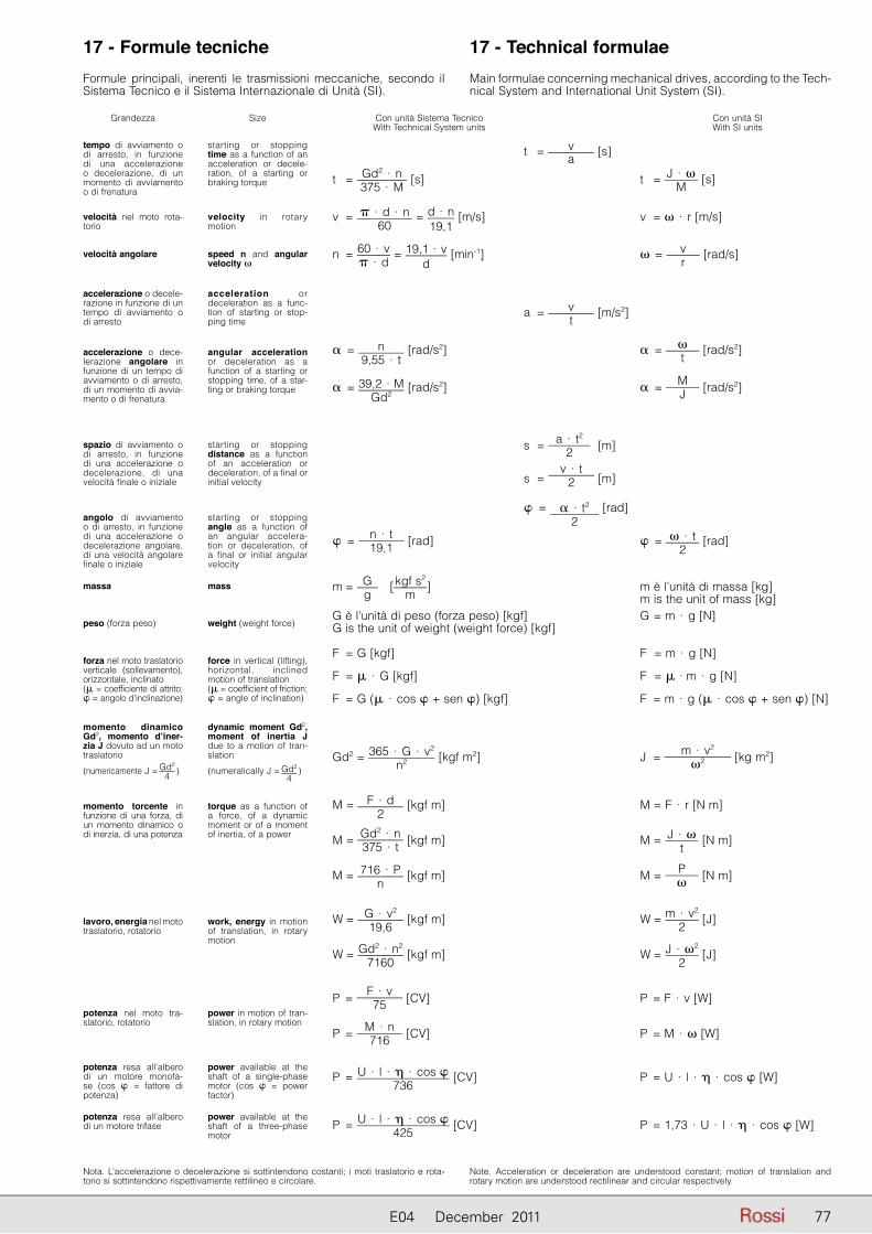
7777E04 December 2011
t = v
a [s]
t = Gd2 · n375 · M
[s] t = J · �M
[s]
v = � · d · n60
= d · n19,1
[m/s] v = � · r [m/s]
n = 60 · v� · d
= 19,1 · vd
[min-1] � = vr
[rad/s]
a = vt
[m/s2]
� = n9,55 · t
[rad/s2] � = �t
[rad/s2]
� = 39,2 · MGd2
[rad/s2] � = MJ [rad/s2]
s = a · t2
2 [m]
s = v · t
2 [m]
� = � · t2
2 [rad]
� = n · t19,1 [rad] � = � · t
2 [rad]
m = Gg
[kgf s2
m] m è l’unità di massa [kg]
m is the unit of mass [kg]G è l’unità di peso (forza peso) [kgf] G = m · g [N]G is the unit of weight (weight force) [kgf]
F = G [kgf] F = m · g [N]
F = � · G [kgf] F = � · m · g [N]
F = G (� · cos � + sen �) [kgf] F = m · g (� · cos � + sen �) [N]
Gd2 = 365 · G · v2
n2 [kgf m2] J = m · v2
�2 [kg m2]
M = F · d2
[kgf m] M = F · r [N m]
M = Gd2 · n375 · t [kgf m] M = J · �
t [N m]
M = 716 · Pn
[kgf m] M = P� [N m]
W = G · v2
19,6 [kgf m] W = m · v2
2 [J]
W = Gd2 · n2
7160 [kgf m] W = J · �2
2 [J]
P = F · v75 [CV] P = F · v [W]
P = M · n716 [CV] P = M · � [W]
P = U · l · � · cos �736
[CV] P = U · l · � · cos � [W]
P = U · l · � · cos �425
[CV] P = 1,73 · U · l · � · cos � [W]
Con unità Sistema Tecnico With Technical System units
Con unità SIWith SI units
17 - Formule tecniche 17 - Technical formulaeFormule principali, inerenti le trasmissioni meccaniche, secondo il Si stema Tecnico e il Sistema Internazionale di Unità (SI).
Main formulae concerning mechanical drives, according to the Tech-nical System and International Unit System (SI).
Nota. L’accelerazione o decelerazione si sottintendono costanti; i moti traslatorio e rota-torio si sottintendono rispettivamente rettilineo e circolare.
Note. Acceleration or deceleration are understood constant; motion of translation and rotary motion are understood rectilinear and circular respectively.
Grandezza
tempo di avviamento o di arresto, in funzione di una accelerazione o de celerazione, di un mo mento di avviamento o di frenatura
Size
starting or stopping time as a function of an ac celeration or decele-ration, of a starting or braking torque
velocità nel moto rota-torio
velocità angolare
accelerazione o decele-razione in funzione di un tempo di avviamento o di arresto
accelerazione o dece-lerazione angolare in funzione di un tempo di avviamento o di arresto, di un momento di avvia-mento o di frenatura
spazio di avviamento o di arresto, in funzione di una accelerazione o de celerazione, di una velocità finale o iniziale
angolo di avviamento o di arresto, in funzione di una accelerazione o de celerazione angolare, di una velocità angolare fi nale o iniziale
massa
peso (forza peso)
forza nel moto traslatorio verticale (sollevamento), orizzontale, inclinato(� = coefficiente di attrito; � = angolo d’inclinazione)
momento dinamico Gd2, momento d’iner-zia J dovuto ad un moto traslatorio
(numericamente J = Gd2
4 )
momento torcente in funzione di una forza, di un momento dinamico o di inerzia, di una potenza
lavoro, energia nel moto traslatorio, rota torio
potenza nel moto tra-slatorio, rotatorio
potenza resa all’albero di un motore monofa-se (cos � = fattore di potenza)
potenza resa all’albero di un motore trifase
velocity in rotary mo tion
speed n and angular velocity �
acceleration or de celeration as a func-tion of starting or stop-ping time
angular acceleration or deceleration as a function of a starting or stopping time, of a star-ting or braking torque
starting or stopping distance as a function of an acceleration or deceleration, of a final or initial velocity
starting or stopping angle as a function of an angular accelera-tion or deceleration, of a final or initial angular velocity
mass
weight (weight force)
force in vertical (lifting), horizontal, inclined mo tion of translation(� = coefficient of friction; � = angle of inclination)
dynamic moment Gd2, moment of inertia J due to a motion of tran-slation
(numeralically J = Gd2
4)
torque as a function of a force, of a dynamic mo ment or of a moment of inertia, of a power
work, energy in motion of translation, in rotary motion
power in motion of tran-slation, in rotary motion
power available at the shaft of a single-phase motor (cos � = power factor)
power available at the shaft of a three-phase motor

78 E04 December 201178
Indice delle revisioniElenco delle modifi che (Cat. E04 - Edition June 2011 disponibile su www.rossi-group.com)
Pag. 7, 8, 9 : introdotti motori IE2
Elenco delle modifi che (Cat. A04 - Edition December 2011 disponibile su www.rossi-group.com)
Pag. 88: eliminato accessorio «Flangia quadrata per servomotori».
Index of revisionsList of updates (Cat. E04 - Edition June 2011 available onwww.rossi-group.com)
Pages 7, 8, 9 : addition of IE2 motors
List of updates (Cat. E04 - Edition December 2011 available on www.rossi-group.com)
Page 88: elimination of accessory «Square fl ange for servomotors».

7979E04 June 2011

Responsabilità relative ai prodotti e al loro usoIl Cliente è responsabile delle corretta scelta e dell’uso del prodotto in relazione alle proprie esigenze industriali e/o commerciali, salvo il caso in cui l’utilizzo sia stato raccomandato da personale tecnico Rossi, debitamente informato dal Cliente delle proprie necessità operative. In questo caso, tutti i dati necessari per la selezione dovranno essere comunicati fedelmente e per iscritto dal Cliente, riportati nell’ordine e conferma-ti da Rossi. Il Cliente è sempre responsabile della sicurezza nell’ambito delle applicazioni del prodotto. Nella stesura del catalogo è stata dedicata la massima attenzione al fine di assicurare accuratezza delle informazio-ni. Tuttavia Rossi non può accettare responsabilità dirette o indirette per eventuali errori, omissioni o dati non aggiornati. A causa della costante evoluzione dello stato dell’arte, Rossi si riserva la possibilità di apportare in qualsiasi momento modifiche al contenuto della presente pubblicazione. Il responsabile ultimo della selezione del prodotto è il Cliente, salvo accordi diversi debitamente formalizzati per iscritto e sottoscritti dalle Parti.
Product liability, application considerationsThe Customer is responsible for the correct selection and application of product in view of its industrial and/or commercial needs, unless the use has been recommended by technical qualified personnel of Rossi, who were duly informed about customer’s application purposes. In this case all the necessary data required for the selection shall be communicated exactly and in writing by the Customer, stated in the order and confirmed by Rossi. The Customer is always responsible for the safety of product applications. Every care has been taken in the drawing up of the catalog to ensure the accuracy of the information contained in this publication, however Rossi can accept no responsibility for any errors, omissions or outdated data. Due to the constant evolution of the state of the art, Rossi reserves the right to make any modification whenever to this publication contents. The responsibility for the product selection is of the customer, excluding different agreements duly legalized in writing and undersigned by the Parties.
Registered trademarksCopyright Rossi S.p.A.Subject to alterationsPrinted in ItalyPublication data4002BRO.ECO-it1211HQM 4002BRO.ECO-en1211HQM
Rossi S.p.A.
Via Emilia Ovest 915/A41123 Modena - ItalyPhone +39 059 33 02 88fax +39 059 82 77 74e-mail: [email protected]
AustraliaRossi Gearmotors Australia Pty. Ltd.AU - Perth WAPhone +61 8 94557399fax +61 8 94557299e-mail: [email protected] BeneluxHabasit Netherlands B.V.NL - NijkerkPhone +31 33 247 20 30Fax: +31 33 246 15 99e-mail: [email protected]
CanadaRossi GearmotorsDivision of Habasit Canada LimitedCA - Oakville, OntarioPhone +1 905 8274 131fax +1 905 8252 612e-mail: [email protected]
ChinaRossi Gearmotors China P.T.I.CN - ShanghaiPhone +86 21 3350 5345fax +86 21 3350 6177e-mail: [email protected]
DenmarkHabasit ABDK - 3400 HillerødPhone +45 48 28 80 87fax +45 48 28 80 89e-mail: [email protected]
France Rossi Motoréducteurs SARLF - Saint PriestPhone +33 472 47 79 30fax +33 472 47 79 49e-mail: [email protected]
GermanyRossi GmbHD - DreieichPhone +49 0 172 6570440 e-mail: [email protected]
India Rossi Gearmotors Pvt. Ltd.IN - CoimbatorePhone +91 422 262 7879fax +91 422 262 7214e-mail: [email protected]
New Zealand Rossi Gearmotors New Zealand Ltd.NZ - AucklandPhone +61 9 263 4551fax +61 9 263 4557e-mail: [email protected]
PolandRossi Polska Sp.z o.o.PL-WrocławPhone: +48 500 418 505e-mail: [email protected]
Portugal Rossi Motorreductores S.L.E - Viladecans (Barcelona)Phone +34 93 6377248fax +34 93 6377404e-mail: [email protected]
Spain Rossi Motorreductores S.L.E - Viladecans (Barcelona)Phone +34 93 6377248fax +34 93 6377404e-mail: [email protected] www.rossimotorreductores.es
Sweden Habasit ABS - 430 63 HindåsPhone +46 301 226 00fax +46 301 226 01e-mail: [email protected]
TaiwanHabasit Rossi (Taiwan) LTD.TW - Taipei HsienPhone +886 2 22670538fax +886 2 22670578e-mail: [email protected]
Rossi Turkey & Middle EastTR - Çiğli - IzmirPhone +90 5303007772e-mail: [email protected]
United Kingdom Habasit Rossi LimitedUK - CoventryPhone +44 2476 644646fax +44 2476 644535 e-mail: [email protected] www.habasitrossi.co.uk
United StatesRossi GearmotorsA Division of Habasit AmericaUS - SuwaneePhone +1 800 931 2044fax +1 678 288 3658e-mail: [email protected]