e. m. y. c. - tdl
TRANSCRIPT
E. M. Y. C.
Il i
"•')> i l l , , , '
' I t
^ " « " ^ ^ » T " ^ T f
, : ' ' l l | l | l l
: ' T i '•*^^PmH>»%f .Lk"^'^k-.'^^^'''!t'»''

Eagle Mountain
Yacht Club
Fort Worth, Texas
Presented to
Dean Lawrence Garvin
DIVISION OF ARCHITECTURE
TEXAS TECH UNIVERSITY
In Partial Fulfillment
of the Bachelor of Architecture
Degree
by
Jeffrey S. Forrest
Dec. 11, 1981
./'. ,
DEDICATION:
To :
-My Parents, without who's neverending moral and financial support none of this could have happened
-My friends, for helping me out when times got bad
•Myself, because I am getting it done!!

T A B L E O F C O N T E N T S
INTRODUCTION 1
BACKGROUND 3
GOALS AND OBJECTIVES 17
ACTIVITY ANALYSIS
SITE ANALYSIS 47
SPACE SUMMARY 62
DETAILED SPACE LIST 74
SYSTEMS PERFORMANCE H O
COST ANALYSIS 114
CASE STUDIES 121
APPENDIX A - SUPPORTING DOCUMENTS 124
APPENDIX B - BOAT HANDLING EQUIPMENT 127
APPENDIX G - CITY OF AZLE "WORKING NOTES" Separate Submittal
APPENDIX D - CONSTRUCTION STANDARDS FOR PRIVATE SEWAGE FACILITIES Separate Sumittal
BIBLIOGRAPHY 136
wiUAUja?*tJBie_"„'L. _

INTRODUCTION

INTRODUCTION
Sailing is enjoying great popularity
in the Fort Worth Metroplex area. Boats
are so numerous on the area lakes that
adequate storage is in short supply.
Owners of storage facilities ask for and
receive practically any amount they wish
for the use of their limited commodity.
Hence, a continous demand exists for
storage facilities of any kind. The
facility designed as a result of this
program should provide storage facilities
in optimum quality and quantity as well
as a "club" facility of quality com
mensurate with the storage provisions.

BACKGROUND

•%,
BACKGROUND
As a result of modern technology
today's working men and women are faced
with an ever increasing amount of "free"
t ime.
"The working week has dropped from an estimated 70 hour, six-day week in 1850 to the present norm of a 40 hour, five-day week with strong movements in the direction of a 35 hour, four-day week..."
Recreation and Leisure Defined
Recreation and Leisure have become
more than activities which happen in
one's spare time or when one is not
working. The actual socio/psychological
aspects of this new million dollar
industry will be discussed in greater
detail in the Activity Analysis section.
For the moment let it suffice that
these periods; of repose should be
considered separate from their work
counterparts. One must also understand
that recreation and leisure are not
synonymous, but in fact, variations.
Websters Dictionary defines recreation
as "to create anew,... refreshment of
strength and spirits after work." and
leisure is defined as "freedom provided
by the cessation of activities; time
free from work or duties" thus, recre
ation can be implied to mean activity
that takes place when leisure, or the
abscence of work exists. Leisure implies
a more intellectual and passive ful
fillment, whereas recreation carries
more active, action oriented implications
While not synonymous, recreation and
leisure are interdependant, and when
providing for one, one must also consider
the requirements of the other.

Recreation Needs Researched
The need for recreation has been
recognized in all branches of society.
From industrial companies who build
extensive recreational facilities for
the use of their employees in an effort
to bolster employee relations, to the
Congress of the United States, who by
public law 85-470 established the Out
door Recreation Resources Commission
(0.R.R.R.C.). Their task was to survey
existing recreational facilities,
trends and use patterns and to make recom
mendations as to the activities which
will experience the largest rise in popu
larity and the facilities which will
require the most development to meet the
rising demand. The O.R.R.R.C. made their
report to the President and Congress in
January of 1962. The introduction of the
National Outdoor Recreation Policy states
"It shall Policy, t servation resources develop, ble to al such quan of outdoo will be n des ireabl enj oyment the physi and splri outdoor r
be the National hrough the con-and wise use of , to preserve, and make accessi-1 American people tity and quality r recreation as ecessary and e for individual and to assure
cal, cultural, tual benefits of
ii4 ecreation
Summarizing from the report of the
O.R.R.R.C., certain factors can be singled
out :
Demand for outdoor recreation is surging. The population of the United States should double by the year 2000, and the demand for recreation triple (1962 figures).
Demand is spread over the entire U.S. concentrating in areas of highest population density.
Recreation must be made
available to the people where they are in close proximity to their homes.
4. Most activity takes place on weekends and after work.
5. Simple activities or ones which require the least amount of specialized equipment and training are the most popular.
6. More specialized sports, while ranking low in popularity, rank high in personal intensity.
This initial report set an example which
many states have followed, Texas being no
exception. A similar study was conducted
in Texas and a documentation of the
findings, "The Texas Outdoor Recreation
Plan" was published.
Water Oriented Recreation
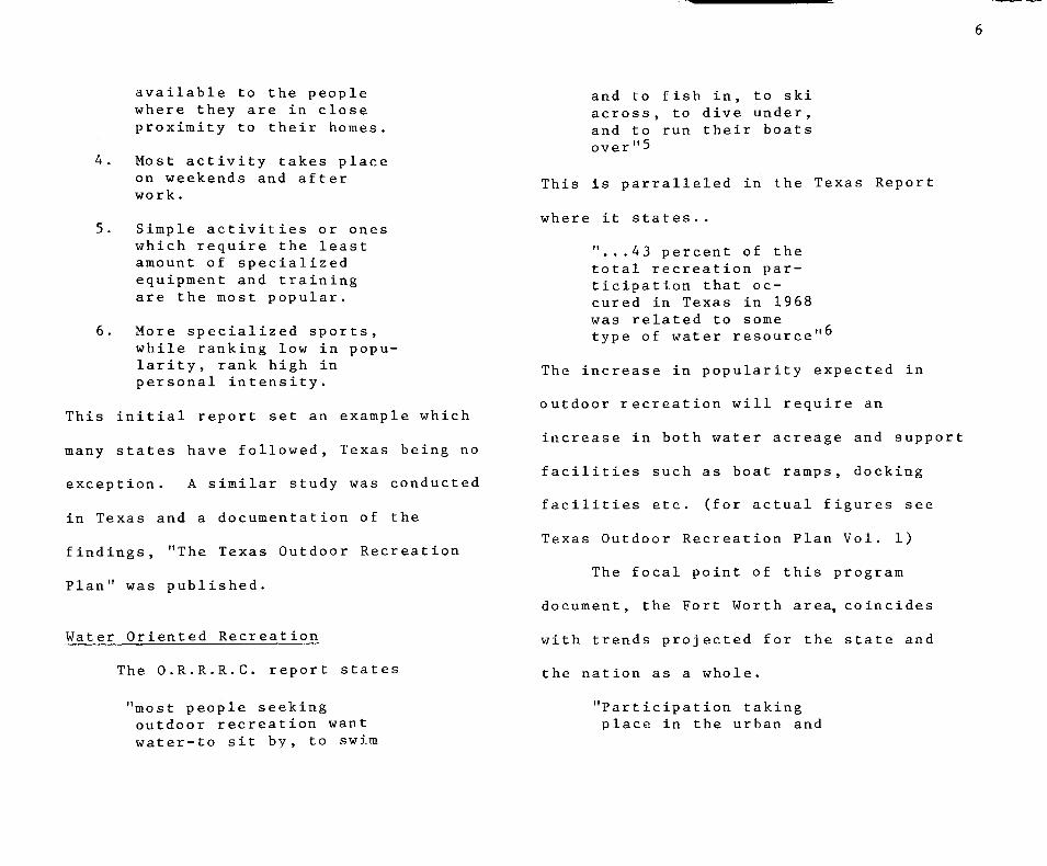
The O.R.R.R.C. report states
"most people seeking outdoor recreation want water-to sit by, to swim
and to fish in, to ski across, to dive under, and to run their boats over"5
This is parralleled in the Texas Report
where it states..
"...43 percent of the total recreation participation that oc-cured in Texas in 1968 was related to some type of water resource""
The increase in popularity expected in
outdoor recreation will require an
increase in both water acreage and support
facilities such as boat ramps, docking
facilities etc. (for actual figures see
Texas Outdoor Recreation Plan Vol. 1)
The focal point of this program
document, the Fort Worth area, coincides
with trends projected for the state and
the nation as a whole.
"Participation taking place in the urban and
rural areas of region 10 is expected to show sihnificant increases from 40.9 million active days in 1968-1970 to 81.2 million days in 1980 and increase of approximately 99 percent."^
(Region 10 consist entirely of Tarrant
County, including the Fort Worth
Metroplex.) Of course, overall popu
lation will increase at an equal or
greater rate, thus intensifying the
need for increased recreational
facilities.
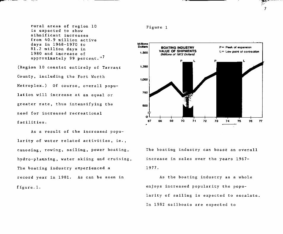
As a result of the Increased popu
larity of water related activities, ie.,
canoeing, rowing, sailing, power boating,
hydro-planning, water skiing and cruising.
The boating industry experienced a
record year in 1981. As can be seen in
f igure.1.
Figure 1
Mi<Hions DoUare
1.500
1.350
1,000
750
500
BOATING INDUSTRY VALUE OF SHIPMENTS
(Millions of 1972 Dollars)
p = Peak of expansion L= Low point o< contraction
67 68 69 70 71 72 75 76 77
The boating industry can boast an overall
increase in sales over the years 1967-
1977.
As the boating industry as a whole
enjoys increased popularity the popu
larity of sailing is expected to escalate,
In 1982 sailboats are expected to
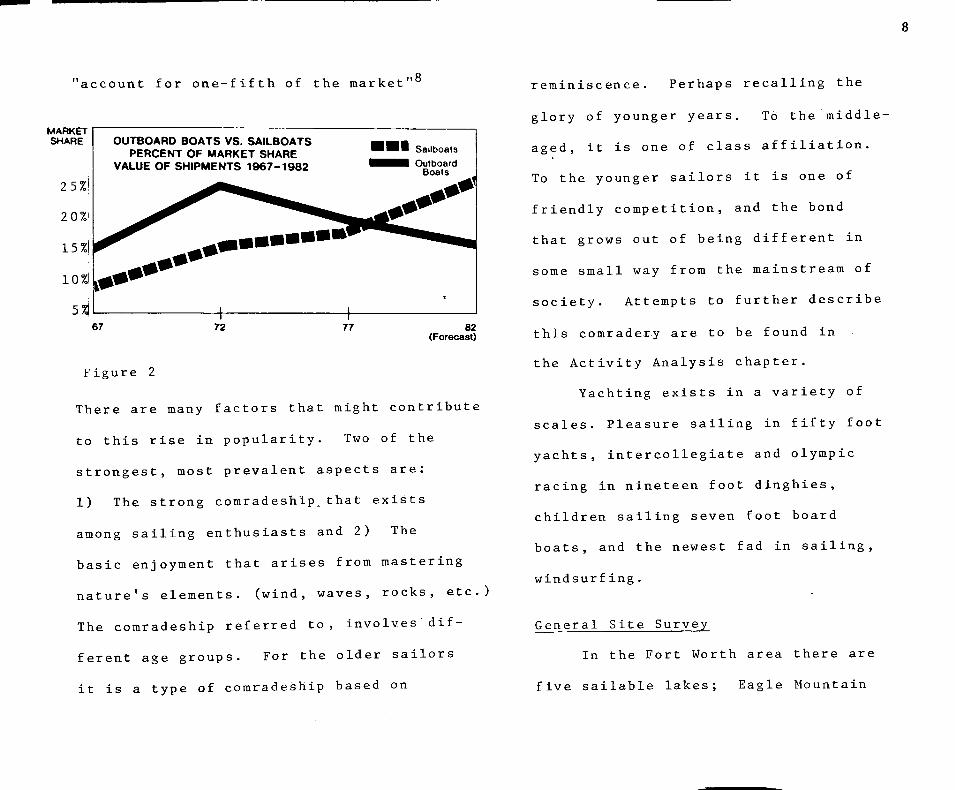
" a c c o u n t f o r o n e - f i f t h of t h e m a r k e t " '
MARKET SHARE
25%!
2 0%'
15%i
10%l
OUTBOARD BOATS VS. SAILBOATS PERCENT OF MARKET SHARE
VALUE OF SHIPMENTS 1967-1982
I I Sailboats • Outboard
Boats
67 72 77 82 (Forecast)
Figure 2
There are many factors that might contribute
to this rise in popularity. Two of the
strongest, most prevalent aspects are:
1) The strong comradeship.that exists
among sailing enthusiasts and 2) The
basic enjoyment that arises from mastering
nature's elements, (wind, waves, rocks, etc.)
The comradeship referred to, Involves dif
ferent age groups. For the older sailors
it is a type of comradeship based on
reminiscence. Perhaps recalling the
glory of younger years. To the middle-
aged, it is one of class affiliation.
To the younger sailors it is one of
friendly competition, and the bond
that grows out of being different in
some small way from the mainstream of
society. Attempts to further describe
this comradery are to be found in
the Activity Analysis chapter.
Yachting exists in a variety of
scales. Pleasure sailing in fifty foot
yachts, intercollegiate and Olympic
racing in nineteen foot dinghies,
children sailing seven foot board
boats, and the newest fad In sailing,
windsurf ing.
General Site Survey
In the Fort Worth area there are
five sailable lakes; Eagle Mountain

Lake, Lake Worth, Benbrook Lake, Lake
Arlington, and Grapevine Lake. Of
these five , Eagle Mountain Lake is
considered by the sailing public to
be the best suited to sailing. The
others being eliminated for reasons of
size, pollution, overcrowdedness, and
degree of separation from the downtown
area. Eagle Mountain Lake is located
on the Northwest side of Fort Worth,
approximately thirty minutes from the
downtown area. The area around the
lake is relatively undeveloped,
rural countryside. Individual homes
line the shores, and residential
developments are scattered throughout
the surrounding country side. A
more complete analysis of the site and
it's demographic surroundings can be
found In the Site Analysis chapter.
The lake's temporal separation from
the downtown area is advantageous rather
than detrimental as one might expect.
The travel time serves to psychologically
separate the individual from the strife
and competition of the work place and yet
is not long enough so as to make the trip
anrduous and tiring one. Many Fort Worth
businessmen who live in the vicinity of
Eagle Mountain Lake enjoy taking advantage
of the relaxing drive home and the tran-
quilizing effect of spending a number of
afternoons each week on their boats.
This would scarcely be possible if one
had to trailer one's boat to the water,
step the mast and adjust the rigging every
time the boat is to be used. Putting
one of these larger boats in the water is
not as easy as it might be with the aver
age motorboat. Some boats require the

10
better part of a day to set up and some
are so heavy that a crane is needed to
place them In the water. The weight and
width of such boats makes towing them to
and from the lake with the family car
impractical, so most owners choose to
store their boats at the launch site.
Types of boat handling equipment are
presented for general reference in
appendix B.
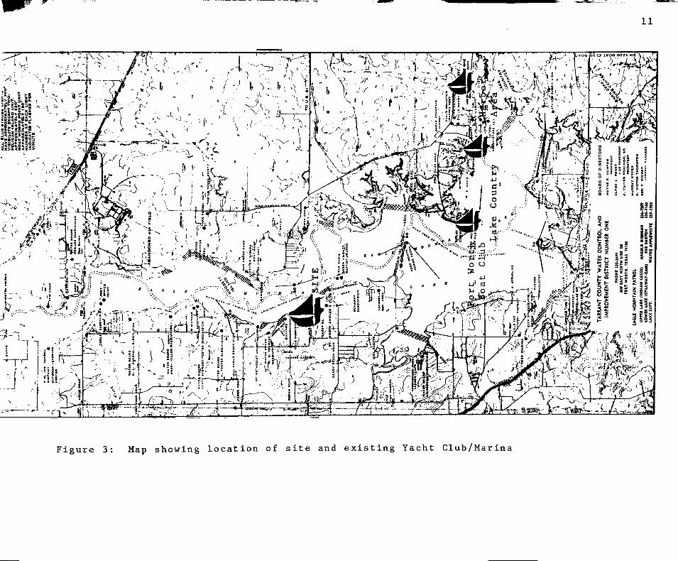
Currently there exist on Eagle
Mountain Lake three yacht clubs and
marinas of significant size. These are
all located in the general vicinity of
the south east sector of the lake and are
grouped relatively close together.
(Reference Figure 3)
Of these three, two are considered
"Yacht Clubs" and one a "Marina". The
combined berthing capacity of the three
is approximately nine hundred slips,
being divided evenly among covered and
uncovered slips. Currently, there exists
no facility wholly devoted to the sailing
public and their special needs. (The
needs of sailing and power boating enthu
siasts being quite different and often
at odds.)
Boat Storage Types
There are many types of storage In
use today. Dry storage on trailors and
slip storage are two of the most popular.
Dry storage is usually for accommodating
small sai.lboats and motorboats, whereas
the larger boats usually require slip
storage. However, it is important to
note that covered slip storage for power
boats Is increasing in popularity. All
boats withstand storage better if they
are in the water because of the con-
11
A -^ z A y ^ ^^R .r^-Wii^iiv-->. v^""4-
<X>&<B<Z=X
•) H
' r '•'-f' -•
J
, , v J ^ ? i . i •»....
I *
: j ^ I <
*^—J a'K ill
V,,., v . . - v \ ^ i
n I- . c
s h •
; * O -I K = ~
0 J 5 1 I ' 5 B S U 1 I U •
tl: i
:: -_ "/'—
..J
> • ^5 ^
i^
-4-i-
- > ^ ) 'T J!^-J;Li4JIX--'i--^-L-!::::-^
->^L^ myv : V
-•\ -OAOU IMK.'J ;Tc™fr^sof^^
isr^ g | si ?§=
•-',4, \^, ><
Figure 3: Hap showing location of site and existing Yacht Club/Marina

12
tinous support the water affords the hull,
much the same as the waterbed supports
the body.
Due to the increased interest in
sailing, lakeside storage facilities are
in short supply. "The situation usually
adopted is the creation of artificial
Yacht Harbors, or Marinas...""
Marina/Yacht Club Defined
At this point it is necessary to
define the two terms Marina, and Yacht
Club, giving special attention to their
similarities and differences. In his
book The Complete Book of Boating,
Earnest A. Zadig describes a Marina as:
"A sort of nautical garage.. A service establishment.. to be judged on the basis of the diversity and efficiency of the services it renders. .10
"The ultimate answer to the problems of berthing and storage . "ll
A situation in which "many owners value
the social aspects of a yacht club more
than the u t ilitar ian "•'• thus, it can
be said that with respect to cultural
values a yacht club Is similar to a
country club. The major difference
being emphasis on sailing, not golf 13
Country Club Popularity
Country Clubs serve a definite pur
pose in today's society. They provide
opportunity for fulfillment of the basic
huir,an need for companionship. The
accompanying golf course offers a green
open space for the enjoyment of friendly
competIt ion.
Site Locati on
As a result of the location of
and A Yacht Club as:

13
existing facilities and planning restrict-
tions imposed by local authorities (see
Site Analysis section) the site chosen for
this proposed new Yacht Club is an exist
ing fishing camp known as Scotty's Camp.
Although Scotty's Camp is currently being
operated as a sort of bait and tackle shop
it also operates roughly a dozen boat slips
Therefore, it is obvious that the harbor
area is suitable for limited sailboat
traf fie.
Economic Analysis
Plans have recently been anriounced
to convert the Sandy Beach area to the
south into a single family housing devel
opment, (see Appendix A) This new
housing development could provide the
nucleus for a strong economic base for a
new Yacht Club. The marketing package of
yacht club and luxury housing has proven
effective in the metroplex area as well
as on Eagle Mountain Lake. The award
winning Chandlers Landing development
in Dallas as well as Lake Country Estates
on Eagle Mountain Lake are two examples
of such successful ventures. "Recreation
has become an'-^essential part of the pack
aging through which housing is offered
to the well-to-do."-'- By taking advan
tage of this concept and developing
housing around the planned Yacht Club,
which serves as the focal selling point,
a solid economic base can be established
upon which to build such a yacht club.
It was as a result of these existing
conditions that the client, Mr. Ronald
Cagle became interested in such a spec
ulative venture. As an investor and
real estate broker in the metroplex area,
Mr. Cagle is well versed in the entrepre-

14
neurial aspects of such a project and as
such will advise on key points as might
create a pleasant club and successful
economic venture.
Housing Considerations
As previously stated, the Yacht Club
is to serve as the nucleus and key selling
point of a new housing development. As
such it is evident that from an aesthetic
viewpoint it is essential that any housing
in the immediate vicinity of the Yacht
Club compliment and reinforce the image
portrayed by the club house area. There
fore, a portion of this program and the
subsequent design shall be concerned with
the preliminary stages of this housing
developmen t.
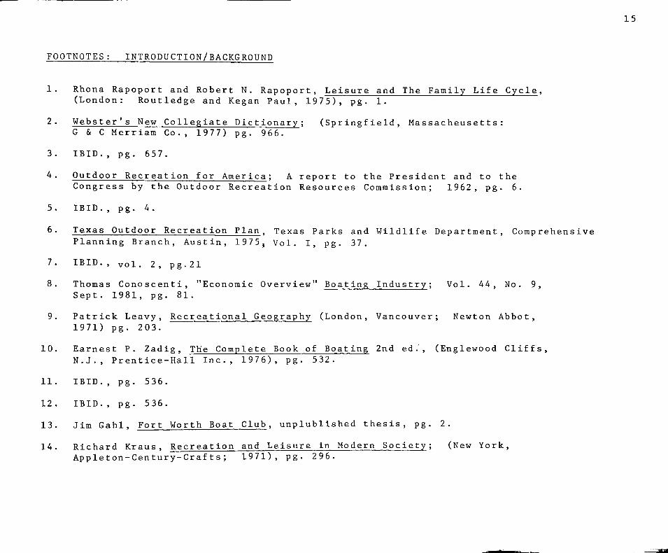
FOOTNOTES : INTRODUCTION/BACKGROUND
15
3,
4
5
6
1.
8
10,
11,
12,
13,
14,
Rhona Rapoport and Robert N. Rapoport, Leisure and The Family Life Cycle, (London: Routledge and Kegan Paul, 1975), pg. 1.
Webster's New Collegiate Dictionary; (Springfield, Massacheusetts : G & G Merriam Co., 1977) pg. 966.
IBID., pg. 657.
Outdoor Recreation for America; A report to the President and to the Congress by the Outdoor Recreation Resources Commission; 1962, pg. 6.
IBID., pg. 4.
Texas Outdoor Recreation Plan. Texas Parks and Wildlife Department, Comprehensive Planning Branch, Austin, 1975, Vol. I, pg. 37.
IBID. , vol. 2 , pg.21
Thomas Gonoscenti, "Economic Overview" Boating Industry; Vol. 44, No. 9, Sept. 1981, pg. 81.
Patrick Leavy, Recreational Geography (London, Vancouver; Newton Abbot, 1971) pg. 203.
Earnest P. Zadig, The Complete Book of Boating 2nd ed., (Englewood Cliffs, N.J., Prentice-Hall Inc., 1976), pg. 532.
IBID., pg. 536.
IBID., pg. 536.
Jim Gahl, Fort Worth Boat Club, unplublished thesis, pg. 2.
Richard Kraus, Recreation and Leisure in Modern Society; (New York, Appleton-Century-Crafts; 1971), pg. 296.

FIGURES: INTRODUCTION/BACKGROUND
Figure 1. Boating Industry, Vol. 44, No. 9 September, 1981, pg. 81.
Figure 2. IBID., pg. 81.
Figure 3. Tarrant County Water Control and Improvement District #1, ort Fort Worth, Texas.

17
GOALS / OBJECTIVES
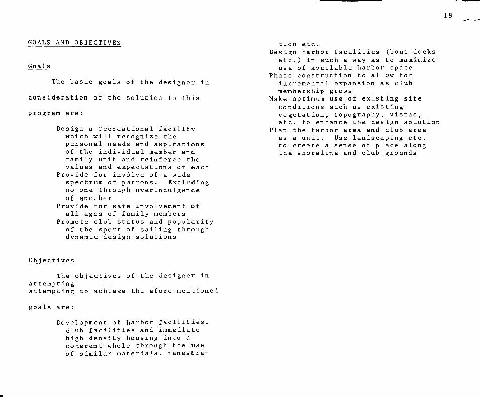
GOALS AND OBJECTIVES
Goals
The basic goals of the designer in
consideration of the solution to this
program are
Design a rec which will personal n of the ind family uni values and
Provide for spectrum o no one thr of another
Provide for all ages o
Promote club of the spo dynamic de
reational facility recognize the
eeds and aspirations ividual member and t and reinforce the expectations of each
involve of a wide f patrons. Excluding ough overindulgence
safe involvement of f family members status and popularity
rt of sailing through sign solutions
Obj ectives
The objectives of the designer in attempting attempting to achieve the afore-mentioned
goals are :
Development of harbor facilities, club facilities and immediate high density housing into a coherent whole through the use of similar materials, fenestra-
18
tion etc. Design harbor facilities
etc,) in such a way as use of available harbo
Phase construction to al Incremental expansion membership grows
Make optimum use of exis conditions such as exi vegetation, topography etc. to enhance the de
Plan the farbor area and as a unit. Use landsc to create a sense of p the shoreline and club
(boat docks to maximize
r space low for as club
ting site sting , vistas, sign solution club area
aping etc. lace along grounds

ACTIVITY ANALYSIS
19
ACTIVITY ANALYSIS
Client Identification
The first and perhaps most important
task in the Activity Analysis of such a
project as this is that of identifying
and analyzing the clientele. The target
group of Yacht Club Membership Com
mittees seems to be families in the
twenty-five to fifty-five age bracket.
Rhona Rapoport and Robert N. Rapoport
deal extensively with this age group in
chapter four of their book Leisure and
the Family Life Cycle, entitled "The
Establishment Phase".
The Establishment Phase
"The central preoccupation of people
is with making commitments that constitute
satisfying life investments".^ These are
investments of the type that affect future
satisfactions and life style possibilities
The decisions and personal time invest
ments made during early years set the
stage for later opportunities. The
Rapoports further divide this phase into
three sub-phases according to children's
age and progress in school. (Note: not
all couples have children, nor do all
couples begin their families at the
same age, but the same problems and
aspirations occur in all with some degree
of regularity) These three "subphases"
are labeled as Early Establishment,
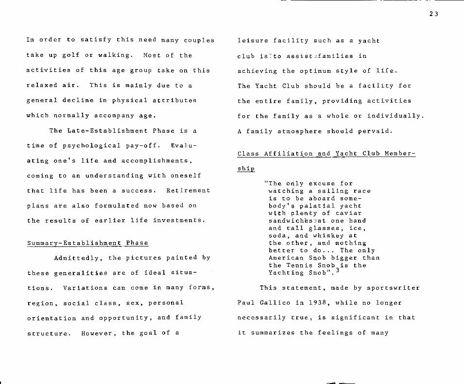
Mid-Establishment, and Late Establishment.
These three along with their corresponding
characteristic preoccupations and poten
tial problems are illustrated in Figure 1.

F i g u r e 1
Sub-phase Preoccupation Potential problems
Early establishment Concern with produc- Conflicts in the (pre-school children) tivity: choices and allocation of one's
plans energies Mid-establishment Concern with per/or- Conflicts of loyalties (children at school) mance: effectiveness; and obligations;
competence at what dissatisfaction is chosen
Late establishment Concern with etia/ua- Depression; boredom; (children out of tion: the meaningful- feelings of entrapment, school) ness of commitments isolation: whether to
(psychological 'pay- change? What? How? off)
As one can see, the three phases also
correspond with the cycles of work and
goal achievement. 1) Working and striv
ing for a desired something, be it
possessions, work status, etc. 2) Con
cern with the quality of experience the
aquisition or goal achievement affords
and 3) Evaluation of one's accomplish
ments, successes, and/or failures,
assessing one's life and preparing for
the retirement years. It is of utmost
importance that the designer of any
20
family related facility do his utmost
to attend to the critical needs of each
phase of adult life. Therefore, a brief
summary of the major characteristics of
each group follows along with some pos
sible key points that might assist the
designer in his work.
Early Establishment Phase
As stated earlier, the major pre
occupation of the Early Establishment
Phase is obsession with productivity,
whether it be work, homemaking, marital
relationships, or child rearing. The
actual field or fields of productivity
are not as important as the mere act of
being productive. This drive towards
productivity extends into the social/com-
munital areas where the man and woman
become involved in as many activities
as possible, both together and as
21
individuals .
Most married couples have children
during these early years, raising the
children and establishing a home become
the focus of much attention. As soon
as the children are born, or the house
is aquired most of the couples' time,
energy, and available money are chan
neled into these two primary interests.
The man's major concern outside of
the home is his work. Establishing him
self in a gratfying job or beginning on
his career are parramount. The woman
centers her interest in the home, or more
recently, on establishing herself in the
job market as well.
The couples in this phase have been
found to have fewer stress related physical
problems. The men are
"...still full of hope and prospects for their work
and careers: They are vigorous and perhaps retain many of the pleasures of their earlier associations and enjoyment of activities. Their wives are for the most part in the "honeymoon" role of the maternal and domestic role cycles and perhaps deriving maximum gratification from having and looking after small infants"^
For this group perhaps the greatest
service a Yacht Club could provide would
be opportunities for the entire young
family to enjoy themselves as a unit in
activities such as picnicing, or anything
where all the family members can enjoy
themselves and be together. The club
might also provide opportunities for the
young business man to entertain business
associates, thereby assisting him in his
climb up the ladder.

22
Mid-Establishment Phase
In the Mid-Establishment Phase the
goals and objectives striven for in the
early phase have hopefully been accom
plished. A plateau has been established
whereby the man is secure in his job".posi
tion and comfortable with his performace
as a father. Likewise, the^woman knows
what kind of mother-she is and may-also
be established inrher ownrcareer.
There is an increase in family
centered activities. Individual activities
such as all male club memberships recede
in favor of such home centered activities
as gardening, family trips, excursions,
and holidays. There is a great push to
enjoy life now. The family is established
economically and can afford to do more of
the things they might have wanted to do
in the early phase. The parents may adopt
an attitude of "do it now while we still
have the time and are together as a
family." Again, the purpose of the club
is to involve the whole family. The
club should be a family activity center
with something to interest every member.
Activities of the younger children need
to be sufficiently supervised so as to
free parents from the burden of worrying
about their chlldrens welfare.
Late Establishment Phase
The late establishment phase is
marked by the children leaving school
and/or the home. Once again the couple
are alone and faced with the task of
getting to know one-another again. New
interests need to be developed, interests
in which both spouses can participate.
There is a need for both partners
to get a moderate amount of exercise.
23
In order to satisfy this need many couples
take up golf or walking. Most of the
activities of this age group take on this
relaxed air. This is mainly due to a
general decline in physical attributes
which normally accompany age.
The Late-Establishment Phase is a
time of psychological pay-off. Evalu
ating one's life and accomplishments,
coming to an understanding with oneself
that life has been a success. Retirement
plans are also formulated now based on
the results of earlier life investments.
Summary-Establishment Phase
Admittedly, the pictures painted by
these generalities are of ideal situa
tions. Variations can come in many forms,
region, social class, sex, personal
orientation and opportunity, and family
structure. However, the goal of a
leisure facility such as a yacht
club is'to assist.'families in
achieving the optimum style of life.
The Yacht Club should be a facility for
the entire family, providing activities
for the family as a whole or individually,
A family atmosphere should pervaid.
Class Affiliation and Yacht Club Member
ship
"The only excuse for watching a sailing race is to be aboard somebody's palatial yacht with plenty of caviar sandwichfes'.'at one hand and tall glasses, ice, soda, and whiskey at the other, and nothing better to do... The only Am erican Snob bigger than the Tennis Snob is the Yachting Snob".^
This statement, made by sportswriter
Paul Gallico in 1938, while no longer
necessarily true, is significant in that
it summarizes the feelings of many

24
yacht club members that sailing and
activities associated with sailing are
connotative of the "Good Life". Yacht
Club activities, correspondingly
are characteristically relaxed with the
exception of the regatta or race which
is quite strenuous.
The concept of associating leisure
activities with upper class affiliations
is in no way new.
"The view of leisure as closely related to social structure stemmed from the writings of Thorstein Veblen, a leading American sociologist of the nineteenth century. Veblen showed how, through the various periods of history ruling classes emerged which Identified themselves most sharply through the possession of leisure".
There are obvious economic reasons why
the sailing public tend to belong to the
white-collar, managerial, professional
strata of society. The equipment re
quired to maintain a boat of any size as
well as the purchase price of most boats
can be formlddable.
Business can also be a motive for aquiring
Yacht Club membership.
"The advertising man's high Involvement in golf, swimming, boating, and tennis may well be linked to the need to do business on the green of in the clubhous e" . -
In summary it can be said that
many of the clientele of a Yacht Club,
no matter what phase of life they may
be in or what their ages may be, belong
to, or aspire to belong to the upper
strata of society. As such, the clientele
can be expected to possess a higher
degree of cultural taste, and demand that
their club facilities reflect and enhance
this point. However, not all Yacht Club

25
Members are comfortable with the rather
stiff atmosphere which has traditionally
been associated with membership. This
group generally consists of younger
people, age twenty-two to thirty, who
express a desire for a more relaxed,
"fun" atmosphere. This is the club's
future membership body. In order to
ensure the continued interest of
these people, the designer must be
careful not to suffocate this new life
with the "stiffness" they find so op
pressive. Balance and coexistance of
the two types of club members is the key.
ACTIVITY ANALYSIS-SPECIFIC
The following activities are those
which are considered of primary nature in
the functioning of any Yacht Club.
Dining
Of all the facilities provided by
the Yacht Club, those for the execution
of the dining and drinking activities
are of greatest importance. The success
of failure of the club is directly re
lated to the successful design of these
spaces. In the competiton among Clubs
for membership, the first lines of bat
tle are the dining and drinking accom-
modat ions.
Food service is varied, most meals
are served ala carte or menu style. Oc
casionally buffet style service is re
quired. The main difference between
these types of food service is patron
turnover. More people can be accommodated
in the buffet style meal because waiting
time is reduced. Greater aisle clear
ances are required for this higher amount
26
of traffic .
Dependant upon the event and the
type of meal being served, participancy
in the dining activities will vary.
Miximum participation will occur at
the evening meal, specifically on
special family emphasis nights. Min-
imun occupancy occurs during the week
day lunch period when most members are
at work.
In order to effectively and ef
ficiently serve this wide range of par
ticipation levels, the spaces designed
for dining must be flexible. However,
flexibility must not be achieved at
the expense of spatial character. The
space must provide a warm and inviting
atmosphere, conducive to the establish
ment of new friendships and the enjoy
ment of existing ones.
Table groupings and placement are
the easist method of accommodating the
wide variety of possibilities existant
in the dining activity. It Is suggested
that tables seating groups from two to
eight people be used. With most emphasis
being placed on tables for two which can
easily be combined to form groups of any
size.
In some instances the number of
diners will exceed the normal expected
capacity of the dining facilities. For
these Instances it is recommended that
overflow areas be provided. These can
take the form of balconies, terraces,
patios etc. This overflow condition
occurs very rarely, hence, the overflow
spaces should also be valid and functional
in themselves.
Further flexibility can be
27
achieved by providing multiple dining
facilities. In addition to the main
dining area provision needs to be made
for smaller, more intimate groups who
desire a great deal of privacy when
engaged in their specific activities.
Privacy is of utmost importance to
these smaller groups.
Another type of dining activity
exists in the club which highly con
trasts with the formal dining here-
tofor mentioned. This other type of
dining is a great deal more relaxed.
Clothing and food service are prime
indicators of this relaxed atmosphere.
Shorts, and other athletic wear are
more likely to be worn by participants
in this dining activity. Hamburgers,
hotdogs, and sandwiches are the com
mon menu items. The atmosphere of
this area Is more "energized" and
"action oriented" than the relaxed,
sophisticated atmosphere of the more
formal dining areas.
Dr inking
Drinking takes place throughout,
and in conjunction with, the dining
activities. However, participants in
drinking activities require an area where
they may indulge freely without fear of
scrutiny by others.
An intimate scale should pervade
this private drinking area. This is the
space where the young club member will
entertain his business guests and as such
should contain the spatial quality ap
parent in the dining facilities.
Frequently, members will arrive at
the club early enough to allow themselves
time for a drink or two before dinner.

28
Often times taking their drinks with
them into the dining area. Hence,
adjacency between the dining and
drinking area is required.
Food Preparation
Food preparation is one of the most
important activities to be considered.
From the managerial stand point the suc
cess or failure of the club hinges on an
efficient and economically operated
food preparation area. The main purpose
of the "kitchen" area is production.
Every design effort must be made to facil
itate a methodical, mechanical plan of
work flow.
Included in the food preparation
area are the Individual activities of.
Food Storage, Food Preparation, Cooking,
Serving, and Cleaning up. Figure 2
illustrates the typical flow associated
F i g u r e 2
CHEF S OFHCE
COMMODnr STORE
DRY EQUIPMENT
GOODS ENTER
WEIGH-IN POINT
COLD STORE
GARDE MANGER
STOVE PARTIES
PREPARATION TABLES
SERVICE COIINTEH
RESTAURANT
STAFF CLOAKROOMS
VEGETABLE STORAGE
VEGETABLE
PREPARATION
WET EQUIPMENT
with these activites. The goal of the
kitchen planner is to provide for...

29
'a continuous flow of goods from sec
tion to section..."^ 'Thus, the perfect
kitchen^from this point of view is one In
which raw, and cooked material need the
minimum amount of movement and requires
only once to cover the same route. -.7
Along with the need to provide for
a smooth work flow in the food preparation
area is the need to provide for adequate
and effective storage space. Storage of
food items generally consists of three
types; dry commodity, vegetable, and
cold storage. The total area needed for
food storage should "...not generally
exceed one-fourth of the kitchen area and
the commodity or dry goods store is sel
dom more than a room representing 8% to
10% of the total kitchen area."^ Allo
cation of space among the three types
of provision storage is variable, and
regulated by the purchasing practices
and menu plans of the individual situa
tion. A good estimate of space needed
can be calculated by alloting "0.2 sq.
ft. of vegetable storage per person ac
commodated in the dining room and 0.4 sq.
ft. of commodity (dry goods) storage..."^
The amount of space required for
actual meal preparation is dependant upon
a number of variables. Foremost among
them being the type of menu and the num
ber of meals to be provided. Simpler
menus and larger amounts of production
tend to demand kitchens with a lower
square foot/patron served ratio. For
purposes of preliminary space allocation,
allow one-third of the space alloted for
dining. "In the case of a Yacht Club or
Country Club the kitchen should be of
sufficient scope to provide service

30
for all dining areas operating at peak
capacity." •'- The design of this space
ahould be such that normal operations at
less than peak load can be efficiently
carried out and still provide for ef
ficiently maximum production.
The food service and storage spaces
should be located centrally among the
dining spaces they are to serve. The
storage spaces should be located adjacent
to a service entrance for ease of deliv
ery, and immediately accessible to the
preparation area.
Retail Sales
Preparation should be made for the
desplay and sale of boat supplies and
miscellaneous items. These items include
clothing, life-jackets, small parts,
electronic accessories and possibly fur
niture. The boating public is proud of
Its nautical heritage and is more than
willing to pay in order to display this
heritage to the world.
A relaxed atmosphere should be pre
sent in this area. High pressure sales
has no place in the Country Club.
The objective of the proprietor of
such a facility is two-fold. The
merchandise selection must be suited to
the particular clientele. This can be
accomplished only through carefull an
alysis and preferably experience. Dis
play of merchandise must also be tailored
to the particular club situation. Sec
ondly, and perhaps more important, the
customer must be made to feel comfortable
and at ease once inside the sales area.
Scattered seating, attractive displays,
and interesting decorative finishes are
elements which help to accomplish this

31
important task. The second objective
gives the designer the most opportunity
to assist in the successful operation of
the retail facility.
"In order to please the customer,
you must first please the woman. "-'--'-
This statement best describes the key to
making the facility comfortable and re
laxing. The logic behind it Is simple
and obvious. A woman who is comfortable
and interested in something in the area
does not pressure her husband Into leav
ing before he has had his chance to
fully examine the latest electronic equip
ment for his boat. Women also buy most
of the clothing and accessories sold,
thus, providing a major source of Income.
Security is of great importance to
a retail sales operation. Vision should
be as unobscured as possible. Access and
egress should be through one, at most
two, easily controllable passages. Cash
ier stands should also be located at each
entrance.
Another, activity separate from
Retail Sales may be accommodated in this
area. Many Yacht Clubs own fleets of
small board boats or even small cruisers.
These can be used by members at any time
with a reservation. Control of these
rentals and charges affiliated with them
can also be accomplished in the retail
area. No special equipment or furnishings
are required for this activity as it
usually entails only the recording of
transactions in a ledger.
The type of proprietorship Involved
with such a retail sales activity also
deserves attention here. It is common
practice among Golf-Oriented Country
32
Clubs for the Golf Pro to operate the
pro shop and cart rentals. A conces
sion type agreement exists between the
pro and the club. A similar situation
is expected in the Yacht Club. Hence,
access must be provided to the propri
etor at any time.
Indoor Recreation
Seasonality is an obvious factor
which affects club membership activity.
Characteristically, and understandably.
Yacht Club activity is at its high point
during the summer months. In order for
the Yacht Club to effectively, serve its
members the year 'round, indoor recrea
tion activities need to be provided for.
Indoor Recreation can be divided
into two classifications; small scale
and large scale. Included In the small
scale recreation area are electronic
games, ping-pong, table games, etc.
While basically a children's area it is
Inevitable that on occasion an adult will
succumb to the mystical lure of the
electronic video game and venture into
the area. As a primarily child centered
activity area the environment created
should be structured towards the adoles
cent body. Anthropometrics of the teen
agers should determine the scale and
furnishings of this area. Refreshments,
in the form of vending machines should
be provided in, or adjacent to, this
space. Special care should also be given
to the accoustical problems created by
such an area. Containment of the noise
created within this area is suggested.
Visual separation of this and other rec
reation areas from the passive dining,
drinking, and relaxation activities

33
is also suggested.
Large scale indoor recreational
activities are associated with the adult
member. Physical fitness is the central
idea for this group. Indoor tennis,
jogging, sauna, whirlpool, etc. are indi
cative of the types of activities being
addressed. The building type most closely
related to this aspect of the club in
terms of similar activities is the Health
Spa. It is not the purpose of the club
to provide all the amenities of the spa.
However, the same activities should be
provided for on a more limited scale.
The space or spaces provided should
promote a friendly atmosphere. For many
participants physical fitness is only a
secondary consideration. The work out
area is rapidly becoming the single's bar
of the 80's. Thus, provision should be
made for casual conversation in as many
situations as possible. Alcoholic
beverages may even be supplied to parts
of this area.
Regatta Organization
Regatta is the term used to describe
a series of sailing races. One of the
major functions of every Yacht Club Is
the organization and sponsoring of one
or more Ragattas per year. The races
are conducted by fleets, fleets being
the division of boats into units compris
ing of boats into units comprising of
boats of similar design and speed. A
race is conducted by a race committee
which controls the start and finish of
the race through the use of a series of
flags and horn blasts. In order to do
this the race committee must have com
plete, unobstructed vision over the
entire race course. This is usually

34
accomplished through the use of a committee
boat. Hwoever, a growing aversion to the
boredom of spending hour after hour a-
board a bobbing committee boat has been
observed. An effort to accommodate this
activity in some sort of land based man
ner is highly suggested. Note that a land
based committee station is only practicle
in races involving small boats. Larger
vessels require courses frequently more
than two miles in length. The committee
boat must move from mark to mark during
these races, thus, it is necessary to use
the traditional committee boat system.
Before a regatta the skippers of
each vessel are called together in what
is known as a Skippers Meeting or Gap-
tains Meeting. In this meeting the
governing rules of the race are discussed
and the general course boundaries estab
lished. This area requires separation
and a degree of isolation from the social
aspects of the club due to the high
degree of importance of the information
exchanged during these meetings and the
importance of complete understanding.
For once the race is underway, it is too
late to ask questions. A view of the
lake from this area is advantageous
because of the helpful possibility of
pointing out land marks to questioning
skippers. Adjacent to this space there
should be space for weather equipment
such as wind vanes, barometers, and wind
speed Indicators which are helpful in
planning race strategies. Due to the
possible high cost of this equipment
security is of course necessary.
In case of a dispute concerning the
rules or some other aspect of a race the

race committee conducts hearings and
hands down decisions which may alter the
outcome of a race. In order to do this
the committee needs the same degree of
privacy as was required in the skippers
meeting. For this reason it is recom
mended that the space created for one
be designed o as to accommodate the
other.
The social aspect of a Regatta is
such that it requires separation of these
facilities from the other social areas of
the club. For often the Regatta is the
biggest event of the year and the atten
dance can number many times the clubs
normal occupancy load. At times of major
regattas most of the site is usually con
verted to some sort of constructed use.
Many racers choose to camp out rather
than stay in an expensive hotel or motel.
Some portion of the lawn area should be
35
allocated for this "tent city".
Many clubs prefer to provide seating
and spectator facilities on the
lawn area rather than in the club
house itself. Some sort of tempo
rary shading device is required for
this activity.
Business Operations
The managerial aspects of a
Yacht Club are similar to those of
any profit oriented business. The
differences occuring in the nature
of club operation. Records must be
kept pertaining to Boat Storage
Rentals, Membership Roles and Ac
counts, Food Service control and
planning, and Boat Repair Services.
The general managerial duties
of the club are under the control
of the club's manager. He may or

36
may not have an assistant, depending
upon the size and scope of the club.
The managers duties are mainly super
visory in nature. He oversees the
operations of all other areas of club
operation. Different Managers may
place a greater or lesser degree of
importance on certain aspects of club
operations, as is their prerogative.
One or two Accountants/Bookkeepers
are usually employed to handle the re
cord keeping duties. All purchases
made in the club are done on a non-cash
basis. (With the exception of some
retail sales.) The member simply signs
his receipts, or meal checks. At the
end of the billing period the bookkeep
ing department prepares a statement of
charges which is presented to the mem
ber for payment.
The chef Is in control of menu
planning, ordering and receiving food
supplies, and coordination of special
dining events. He needs a small, private
space preferably located within or ad
jacent to the food service area.
The harbor master is in charge of
general grounds maintenance and in part
icular. The Harbor Area. He needs a
small space to base his operations from.
Boat Service
Servicing the average sailboat can
be a very involved process depending on
its size and make. Small boats can be
trailered and taken into any suitably de
signed maintenance facility. The real
problem arises when the larger, fixed
keel boats need servicing. Special equip
ment is needed to lift these boats out
of the water and place them in a

37
cradling device. This cradle can then be
moved about on land to the maintenance
area. Close proximity to the water is
advantageous for such a maintenance fac
ility because of the weight and bulk of
these boats. The facility needs to be
large enough to house these large craft
and still supply ample room for maneuver
ing equipment around and above it. Spe
cial attention should be payed to supply
ing overhead lift facilities. A ceiling
height of thirty feet for safe operation
of such cranes is recommended. The actual
maintenance to be done is of such caliber
as to require craftsman quality work in
four areas; fiberglass, carpentry, elec
tronics, and sail repair. Benches and
private work areas for these craftsmen
should be provided with easy access to
the boats. There is also a need for some
kind of facility to assist In mast and
rigging work. This is usually done while
the boat is in the water, prior to being
brought onto land. (see appendix B)
From the owners standpoint the per
iod of repair can be an anxious, question
ing one. Analagous to this is the time
when ones car is.--.being repaired. Even
more directly akin to this would be If
the car in question were a classic or
antique requiring specialized attention.
Not unlike the car owner the boat owner
likes to see what is being done to his
property, but for safety reasons he is
not allowed into the actual work area.
Provision needs to be made for the safe
viewing of work currently in progress,
while maintaining the degree of safety
dictated by cautious planning.

^38
Harbor Area
Obviously the main activity of this
area is the docking and storage of boats.
However, certain amenities are required
by owners, not only for storage but for
occasional activities which may take
place aboard the boat while it is docked.
Some of these activities include parties,
quiet relazation, and light maintenance.
Thus, because of the amount of activity
present at the docks, the atmosphere needs
to create a feeling of "place" rather
than merely a docking facility.
One of the simplest, and yet most
important comfort determining factors
related to docks is that of surface treat
ment. Everyone has experienced walking
across an asphalt street on a hot summer
day and the intense pain inflicted on ones
feet due to the heat absorption qualities
of the surface. As the tendency of most
people around water is to discard their
shoes, the same conditions exist when
one walks out on the dock going to or
from ones boat. Elimination of this
potential discomfort is therefore highly
recommended as onejof thehfirst Steps
toward creating a pleasant docking fac
ility. Other necessities for this area
include electrical power outlets for
lights and recharging ships batteries,
waste disposal units, solid and liquid,
to lessen the temptation to litter the
area, and storage for the boat owner.
This storage is in the nature of extra
life jackets, sails, etc. The type of
equipment that is always needed but not
enough room for on the boat. Therefore,
direct access should be provided from
the boat to this storage.
^39 M^
The concepts of privacy and ter
ritoriality also come into play in the
design of a docking facility. Each boat
owner is immensely proud of his property.
Evidence of this can be found in the
brightly colored sails and spinnakers,
flown from the larger boats, an obvious
attempt at establishing ones identity.
Examples of the attempt to Individualize
and personalize ones ship are abundant,
the names across the stern, the style and
trimmings of the boat, and the occasional
personalization of the slip space itself
are a few. Inspite of this striving for
identity there are limits to the amount
of admiration boat owners endure. Ter
ritoriality and its boundaries are easily
identified. Boat owners have no objec
tions to sharing the dock fingers which
extend out between the boats, but there
exists an imaginary plane having as its
line of demarcation, the line of the
meeting of dock and water. Any penetra
tion of this plane, however slight, may
be cause for discomfort on the part of
the infringed. Reactions may vary ac
cording to the individual and the type
of infringement. Reactions range from
slight discomfort for someone touching
the boat to, irrate outbursts at catch
ing someone actually aboard the boat.
These tendencies naturally, should have'',',
great influence on the designer. Every
effort should be made to lessen the op
portunities for confrontation.

40
Outdoor Recreation
As noted in figure 3, the most pop
ular outdoor activities in 1960-1961 were
driving for pleasure, walking for pleasure,
outdoor games, sports, and swimming.
>'uab«r of - \cc lvl ty Oavs 3«r persoa, L2 .-ears and Jutia I , L960-M«y 30. .961
Horseback R l d i a g H l . 2 5
Camping ^ 1 . S6
Ice S k a c l a g | . 3 3
Sledding 1 . 5 ^
Hiking I -^2
'-'acer S k l l n g l - ^ i Coacerca B . 39
Canoeing I. L2
Sa i l ing 1.11
Mouncain Cl lab iag l . 09
Snow S k i i n g | . 0 7
F i g u r e 3
With possible exception of driving for
pleasure it can be inferred that these
activities enjoy the same popularity today
Figure 4 more closely correlates the pop
ularity and time duration associated with
the activities a Yacht Club might be par
ticularly conducive to. As a result of i
the information presented in these two
charts, interviews, and case studies the
following is a list of suggested outdoor
activities to be considered by the design
er
Swimming Walking Picnicking Fishing Bicycling Basketball Shuffleboard Tennis
Indoor support facilities should also be
provided for these activities. Sauna,
Whirlpool, and Locker Room facilities
are examples. It is important that the

4 1
PERCENTAGE OF POPULATION 12 YEAKS \N0
OVER PARTICIPATING EACH S IMICL = S-.
JUNE-AUSUST, I960
SWIMMING
SIGHTSEEING r r r v r r r - f A-l / - \ /-»
FISHING Wj • / / *fj *yj rlj k . 29
BOATING J. J. J. J. ^ "
BICYCLING l4^ J l 9
NUMBER OF DAYS PER PERSON
EACH STMIOL = I OAT
^ ^ fe g l ^ 1 S'5
C ^ & ^ ( «3«
fi ^ 1,99
£ l I 1.22
^ g I.7S
F i g u r e 4
arrangement of these activities on the
site not interfere with or detract from,
the most advantageous views of and/or
from the clubhouse.
Hous ing
As previously stated, the connection
between the Yacht Club and immediate
housing is so strong that the design of
the Yacht Club should Influence at least
the exterior appearance of said townhouse
development. However, the scope of this
project is such that emphasis is to be
placed on the Yacht Club and the general
development of the site into a successful
leisure/recreation complex. Secondary
to this is the design and arrangement of
the townhouse development. A basic
understanding of the activities and needs
of the townhouse dwelling family is re
quired for even preliminary design con
sideration, and to determine the proper
geographic fit on the sight.
The following is a summation of the
Activity Analysis contained in the
Architectural Thesis Program, "A Town
house Community for Lake Ray Hubbard,
Dallas" by Marianne Medlin. The scope
and character of this project is somewhat
similar to the one discussed here and
the activity analysis presented is well
documented and of such quality that it
can be considered a authoritative, if
brief, source.

42
The basic unit of the community is
the family, and the basic unit of the
family - the individual. Thus, built
upon the individual, all three possess
the same "needs for territory, privacy,
identity, orientation, convenience, ac
cessibility, and safety, without which
an individual cannot feel the fulfillment
of true individuality"-'-^ hence, family
and community individuality. For sim
plicity for the duration of this dis
cussion on housing, when the individual
is discussed it can be inferred that the
same holds true for the family and the
community. This is of utmost importance
when one remembers that It is the complex
as a whole and the interelationship
between the individual dwelling units
that this program is concerned with.
"The control iver physical space which territoriality implies
becomes a means of enabling the individual or group to attain privacy, which in turn signifies the ability to control those events occurring in ones immediate environment."-'--*
There are differing degrees of privacy
needed for various activities within
the dwelling. The degree of privacy
required by various activities is
better graphically displayed in figure
5 & 6.
The family defines its territory as
the dwelling. Behind its walls the family
is free to build
"...A sense of family solidarity through shared experiences and activities, op-ortunlties for dia logues between all members, and the setting for learning how to form bonds with other human beings."-*-^

43
Figure 5
Thus, a man's house i^ his castle and
defense of it against intruders is para
mount .
"The ritual entrance into this sacred territory, the threshold."l^
For this reason it is necessary that
entrances in multi-family housing be
protected, identified, and above all
individual.
The orientation of a house, its
placement of windows, the views it pre
sents and vistas it provides for it's
inhabitants express the family's view of
their neighbors and community. In the
case at hand it is obvious that the
townhouses and the Yacht Club and
possibly other facilities on the sight.
In developing and planning the areas
in and around the housing development
three elements should be kept in mind;
convenience, accessibility, and security.
Convenience is defined as the "degree of
physical ease of lack of difficulty in
going about ones activities from day to
day within and beyond the boundary of
the home."-'-" "Accessibility refers to

44
the ease of circulating through all
elements of the housing environment."
Security is protection from Invasion of
ones territory from and thing or any one
who Is labeled as dangerous or threaten
ing.
pRCXxnirrr A.\D cmcuiATioN DMGRA.V;
Sleeping iMaking Lovej
'^othmg\ PRIVATE
SOUhD Si SIGHT
SARRIEBS
^^m.^^ / Outdoor \
/3athi!g\ I Suruimg \ „WATE
I Sic* Corel \ j " ^ \ y ^^^^ae?*"-..
; Service = y^Creatm^\\ Child /
Laundry \ V P t o y . , ' * 0 P S M r ; y . .Ifomttnnny ^ '"";i.«o«ii™.«„„ ^
Administering 1 ./^ ""•., CkiU Care 1/ \
Cookvig h '--EatiKg
^ ^ H Outdoor Living
Orirunng \ '^.».,^ Entertainment I
^ Clald Trainingj Recreation J
^'^iA
y
Townhouse Community
The Townhouse Community is unique
among housing developments with the
exception of condominiums in that they
share a sense of territoriality In a
common site. Common areas exist which
are maintained by a homeowners associa
tion. However, the private areas adjacent
to each unit are the responsibility of
the owners. These areas along with the
individuality, the design of each unit
are what give the separate units their
identity.
Inconclusion, the design of the
townhouse complex has three primary
goals. 1) Relate townhouse complex as
a whole to the site development 2) Re
late the individual units to the complex
as a whole and 3) Provide for individual
identity and territoriality.
Figure 6
42
FOOTNOTES: ACTIVITY ANALYSIS
1. Rhona Rapoport and Robert N. Rapoport, Leisure and the Family Life Cycle, (London: Routledge and Kegan Paul, 1975), pg. 186.
2. IBID., pg. 266.
3. Paul Gallico, Farewell to Sport, (New York, London: Alfred A. Knopf, 1938), pg. 330.
4. Richard Kraus, Recreation and Leisure in Modern Society, (New York, Appleton-Century-Crafts; 1971), pg. 296.
5. IBID. , pg. 294.
6. John Fuller, Chief's Manual of Kitchen Management, (Bt Batsford Ltd., London, 1962), pg. 110.
7. IBID., pg. 112
8. IBID., pg. 113
9. IBID., pg. 113
10. Interview with Mel Stuart, General Manager, Hillcrest Country Club, Lubbock, Texas.
11. Interview with Ken Abbott, Owner/Manager "Paddles 'n Sails", Lubbock, Texas
12. Richard Untermann, Site Planning for Cluster Housing, (New York: Van Nostrand Reinhold, 1977), pg.39.
13. Franklin D. Becker, Design for Living, (Ithaca, N.Y.: Center for Urban Development Research, 1974), pg.l6B.
14. Satenig S. St. Marie, Homes are for People, (New York: John Wiley and Sons, Inc., 1973), pg. 5.

15. Marianne Medlin, A Townhouse Community for Lake Ray Hubbard, Dallas, (Unpublished Thesis), pg. 16.
16. Untermann, pg. 43
17. Medlin, pg. 20
L

46
FIGURES ACTIVITY ANALYSIS
Figure 1. Rhona Rapoport and Robert N. Rapoport, Leisure and the Family Life Cycle, (London; Routledge and Kegan, Paul,'1975), pg.
Figure 2. John Fuller, Chief's Manual of Kitchen Management, (B.T. Batsford LTD., London, 1962), pg. 111.
Figure 3. Outdoor Recreation for America: A report to the President and the Congress by the Outdoor Recreation Resources Commission, 1962, pg.34
Figure 4. IBID., pg. 36.
Figure 5. Robert Keenedy, The House and the Art of Its Design, (New York: Reinhold Publishing, 1953), pg. 109.
Figure 6. IBID., pg. 112

47
SITE ANALYSIS

48
SITE ANALYSIS
Site Analysis-Physical
The site chosen for this recreational
development Is a 31.76 acre tract on the
west shore of Eagle Mountain Lake, Tarrant
County, Texas. The land currently belongs
to Mr. B.R. Scott who is offering the
tract for sale.
Geographic Location
Tarrant County is located in North
Central Texas. The Fort Worth metro
politan area occupies almost all of
Tarrant County and accounts for 97% of
Its population.
Tarrant County Line
Figure 2 : Map showing Tarrant County limits and Fort Worth city limit s
Figure 1; Map showing location of Tarrant County
49
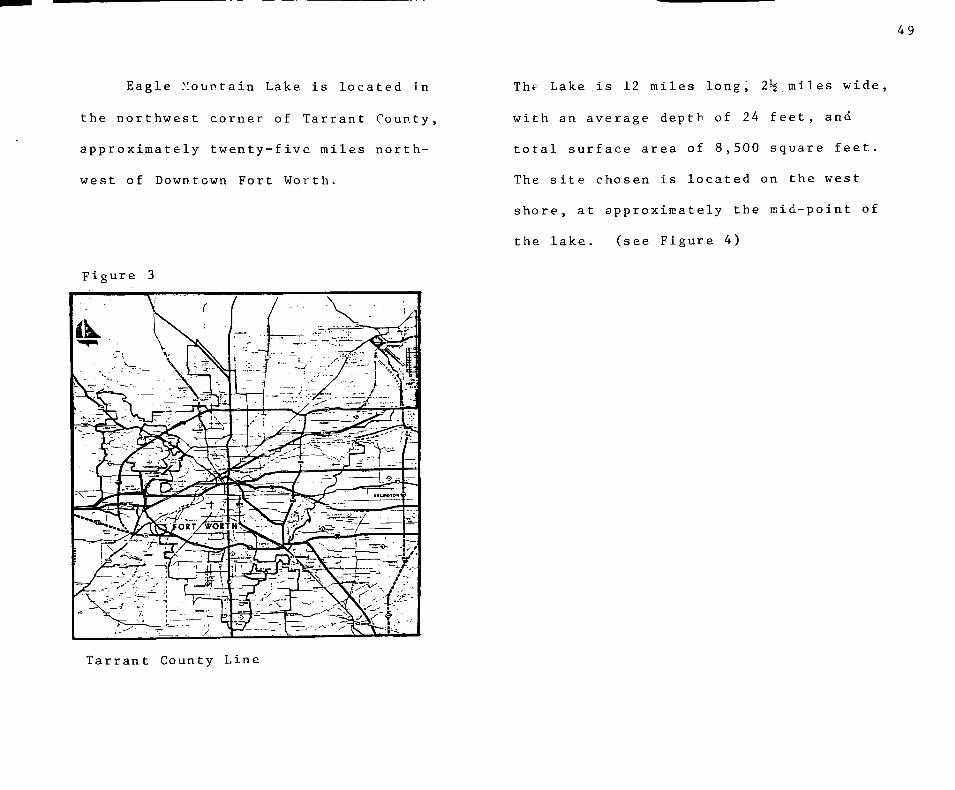
Eagle Mountain Lake is located in
the northwest corner of Tarrant County,
approximately twenty-five miles north
west of Downtown Fort Worth.
Figure 3
The Lake is 12 miles long, 2*5,miles wide,
with an average depth of 24 feet, and
total surface area of 8,500 square feet.
The site chosen Is located on the west
shore, at approximately the mid-point of
the lake. (see Figure 4)
Tarrant County Line

50
• 8 H V j
-<x>ft .<a<z-S ' • \ l iM«—,
^ /
P! v ;
; ?- ^
, ' 1 K . , ••) l y / / I » v . v V " ^ i •\ t- ' "- '. •»• • • JjyoH 5 m D i»oa o i z i H ^ ' , ^-
.^! 1 1 , ' - - - • ; ? ^
^ ^ .V A J I, / v - ,' ^, -. • ^y y^. \ ^ 'r y /y-'w. •• N . ' ^ • k .. *N ^ < . - r ^ . | , V » ^ ^ . \ • - - •• .' "• ^ Zi-'J r~^r. >-~li
„ "••gv.:;:^^
•"' ? li ^ £ « ! iS
< I e I S t . O • > 2
/WiiJi^iii • v ^ 1 *f " y 2 £ 2
-j
5 ! h"
/i .^_
-1- 1-
si- : . - . l ' . - t - : -:A'
\ i> ./:, I
- ''1 ! --— 'I t
F i g u r e '4 : Map s h o w i n g l o c a t i o n of s i t e

51
Orientation
As figure 5 indicates, the site is
situated on the west side of a small
inlet. The east property line is also
the lake shoreline and extends from
the mouth to the innermost point of the
inlet. The site is bounded on the north
by County Road 4117, on the west by
private property, and the south by
Tarrant County Water Control Board Prop
erty .
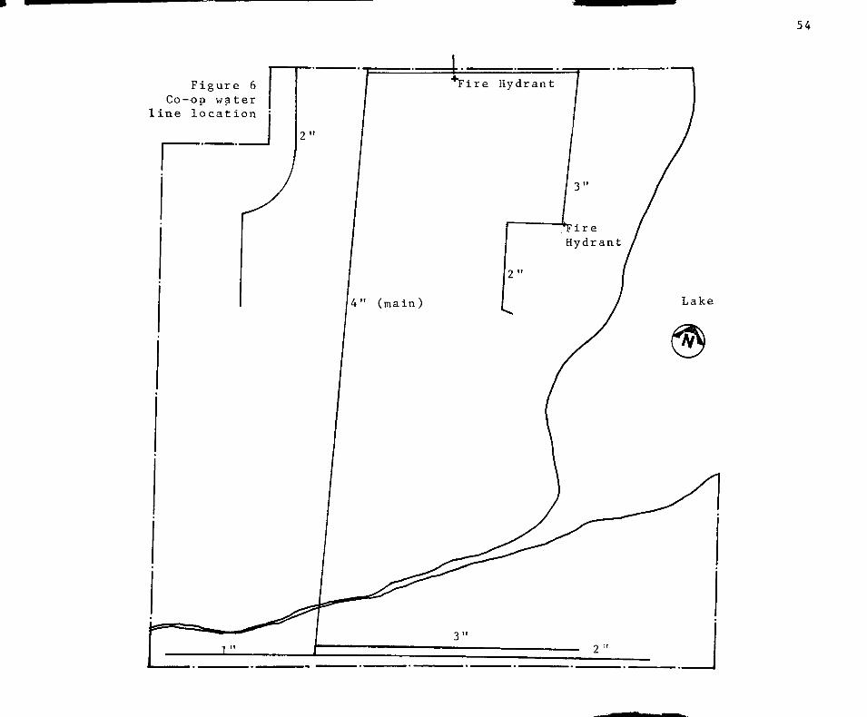
Utilities
Electricity and Co-op water are sup
plied to the site. (see Figure 6) The
waste disposal system must be independant
and self-contained in nature since there
are no provisions for municipal treatment
A guide entitled "Construction Standards
for Private Sewage Facilities" is Includ
ed in in Appendix "D" for the designer's
use. This is a copy of the standards
adhered to by the T.C.W.C.B. and the
City of Azle and as such serve as suf
ficient guidelines for realistic design
parameters.
Figure 5

52
SITE ANALYSIS-JURISDICTIONAI
City
The site is located within the five
mile Extra Territorial Jurisdiction
(E.T.J.) of the City of Azle. Azle has a
policy of exercising-igreater control
over its E.T.J, than most other cities.
Any developer who proposes to subdivide
any plot of land in this area must have
his plans approved by the planning depart
ment of the City of Azle. The same
zoning restrictions are applied to this
area as would be applied to a project
within the city limits. Therefore, a
copy of the Azle Planning Gommisson's
"working notes" for contractors con
sideration is included in Appendix. "C"
for the designers consideration.
T.C.W.C.B.
The waters edge marks the boundary
of the Tarrant County Water Control
Board's Jurisdiction. Eagle Mountain
Lake belongs to the T.C.W.C.B. and as
such, any projections into the lake must
be approved by them. In order to be
allowed to build a facility, such as a
Yacht Club with its dependencies on the
water one must first present a detailed
plan of development including financial
data to the board for approval. Upon
approval by the board the project owner
is granted a concession type access to
the lake for which the board receives a
certain percentage of the project's
gross income, (usually 8-10%)
All projections into the lake must
be designed by an approved engineer.
Dredging i.s allowed, however, approval
53
from the Federal Government is required
and this can be a lengthy process.
Harbor capacity as determined by the
T.C.W.C.B. is a subjective matter. Lake
Patrol Officer Harold Bierman, a veteran
of thirty-five years is the representative
who estimates the number of boats a
harbor area can accommodate safely. When
asked about capacity of the harbor
chosen for this site Mr. Bierman replied,
"With modern technology, and new facil^
ities, I think one hundred sailboats
would be a reasonable estimate." While
this estimate can in no way be considered
scientific, it is based on thirty-five
years actual experience and as such will
be used as the preliminary estimate
for harbor capacity. Through the design
process a more accurate capacity should
be calculated, however, this preliminary
estimate will be used for a base In
determining facility occupancy levels.
54
Figure 6 Co-op water
line location
55
Site Conditions
Currently there exist on the site,
several older frame structures. Most of
these are small frame cottages that have
been built on land leased from Mr. Scott.
The other existing structure Is the Marina
Facility. It functions as a bait and
supply' store and is in a general state
of disrepair. Most of the structures on
the site exhibit this same state. The
property is to be sold as a whole and is
therefore subject to development as a
whole.
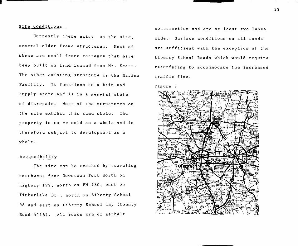
Accessibility
The site can be reached by traveling
northwest from Downtown Fort Worth on
Highway 199, north on FM 730, east on
Timberlake Cr. , north on Liberty School
Rd and east on Liberty School Tap (County
Road 4116). All roads are of asphalt
construction and are at least two lanes
wide. Surface conditions on all roads
are sufficient with the exception of the
Liberty School Roads which would require
resurfacing to accommodate the increased
traffic flow.
Figure 7

46 ^
SITE ANALYSIS: CLIMATOLOGIGAL/• TOPOGRAPHICAL
Climate
Moderate is the key word when one
attem.pts to descrive the climate of the
Fort Worth area. Temperatures are mild
with the average in the mid sixties.
Periods of extreme weather are short
lived so relief from whatever discomfort
is not far off. Annual precipitation is
34.55 inches and average relative humidity
is 63%. Fair skies, southerly winds and
dry air are the norm during the sum.mer
months. Winds, the element of nature
most important to a Yacht Club and sail
ing are relatively constant and from a
generally southerly direction. Fig. 8
R a i n f a l l 5
w 4 tu
si 3 o C 2
1 '
1) i >-. i J . •
100
90
80
70
60
H U
30
/. u
1 0
.
-
. . . (U i >^
Temp
u
at ure
• • • n ) a ) c d o . r t 3 3 3 < u a o ( U i - i f e S - a J S T ) i - j < 3 c n o S Q
Vegetation
Located in the cross timbers geo
graphic region of Texas, Tarrant County
has as its characteristic vegetation
Poast Oak and Black Jack and is dotted
with prairies and different grasses. (Fig. 10)
Soil
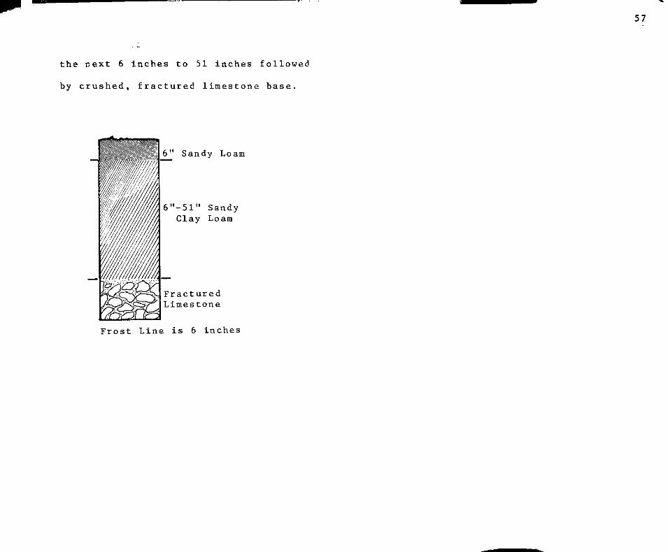
Terrain in the site area has an
average slope of 5%. A core sample of
the area would show a surface layer of
fine, brown, sandy loam for 6 inches
and subsoil of sandy clay loam for
^ r?. s s ^ ^ ^ < ^ C^ ^ n
mMtue^--^-- : -.—-
57
the next 6 inches to 51 inches followed
by crushed, fractured limestone base.
6" Sandy Loam
6"-51" Sandy Clay Loam
Fractured Limestone
Frost Line is 6 inches
59
SITE ANALYSIS-DEMOGRAPHIC/LAND USE
Demographi c
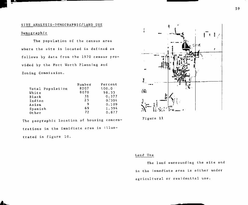
The population of the census area
where the site is located is defined as
follows by data from the 1970 census pro
vided by the Fort Worth Planning and
Zoning Commission.
Total Popula White Black Indian As ian Spanish Other
tion Number 8207 8070
31 25 9
69 72
Percent 100.0 98. 33 0.377 o:-3 04 0. 109 1.394 0.877
The geographic location of housing concen
trations in the immidiate area Is Illus
trated in figure 10.
Figure 11
Land Use
The land surrounding the site and
in the immediate area is either under
agricultural or residential use.

60
SITE ANALYSIS: EAGLE MOUNTAIN LAKE
Eagle Mountain Lake is one of
three lakes comprising The Tarrant County
West Fork Lake System of the Trinity
River basin. The other two are Grapevine
Lake and Bridgeport Reservoir. The main
purpose of these lakes is to serve as
a water source for the Fort Worth area.
They also provide a limited amount of
flood control.
As a result of this three river
system the level rarely rises more than
two feet. Recently, however, the water
rose an estivated 10' damaging property
within the flood plane. This incidence
of high water occurs very rarely. For
reasons of safety and common sense
construction within the 10' flood plane
should be kept to a minimum.
61
SITE ANALYSIS: SOURCES
Soil Survey of Tarrant County. Texas. (U.S. Dept. of Agriculture Soil Conservation Service, 1981).
James A. Furrner, The Weather Almanac. (Detroit: Gale Research Book Company).

62
SPACE SUMMARY
63
SPACE SUMMARY
Membership Calculation
The first task facing the program
mer in the development of reasonable
space allocation estimates for a Yacht
Club is determining optimum club mem.ber-
ship, and occupancy. There are many
factors which affect the size of member
ship roles necessary to sustain any club
facility. Among these are membership
dues and other revenue producing aspects
of the club, operating costs, and proxim
ity of other comparable club facilities.
Due to the complex nature of the problem
there are no guidelines established
whereby one can precisely determine member
ship. Therefore, alternate sources of
information must be used In determining
probable membership numbers. Among those
used here-in are case studies of similar
facilities in the Dallas-Fort Worth area.
Personal interviews with country club
managers and r ecom.menda t i ons for Marina
and Country Club planning.
Membership in the golf-orientated
Country Glub is composed of golfers and
non-golfers. The capacity of the golf
course to accommodate a certain number
of golfers is the base to which a per
centage is added to allow for the non-
golfer.
In the Yacht Club the determinant
factor must be the number of boat storage
facilities available to house the club
fleet. In order to accurately determine
the ratio of oon+sailing toj sailing,; club
members, the club m.embership total must be
divided by the number of storage facilities
available. A survey of similar facilities
in the Dallas-Fort Worth area shows a

64
ratio of 2.4 members per boat storage
space to be the average.
At this point It is necessary to
make a preliminary assumption as to
the boat storage capacity of the pro
posed Yacht Club. From estimates of
harbor capacity and composition of boat
storage facilities is derived.
Wet (slip) storage 100 boats , Dry storage 60 boats
Total 160 boats
Multiplying this figure by the ratio
of 2.4 members per boat space, we arrive
at a figure representing appoximate
optimum, club membership.
160 X 2.4 = 384 or 400 members
The composition of this m.embership
Is also important. It is estimated that
85% of club m.emberships are held by
families, the remaining 15% belonging to
corporations or individuals. These factors
give rise to the following calculations.
.85 (400)= 340 family held memberships
.15 (400)= 60 individual memberships
15% Individual Membership
85% Family Membership
Given this composition of member
ship types a figure representing total
occupancy can be calculated:
340 (family memberships) x 4 members/ family -I- 60 Individual memberships = 1420
Common sense dictates that no need exists
to provide for the total number of oc
cupants. _ Practical experience has shown
that approximately 25% of the membership
65
is to be considered active. This gives
an expected occupancy of:
1420 X .25 = 355 occupants
Thus, the following estimates will be
used in determining space allocations
for the Yacht Club Facility.
Membership - 400 Club House Occupancy - 355

66
SPACE SUMMARY - SUMMATION
Section I Sheltered spaces, spaces to be provided for in the built environment, ie. Clubhouse, etc.
42,647 sq. ft
Section II Unsheltered spaces, ancillary spaces not necessarily requiring totally enclosed design solutions, ie. parking, etc.
160,420 sq. ft
Total Project Area 203,067 sq. ft
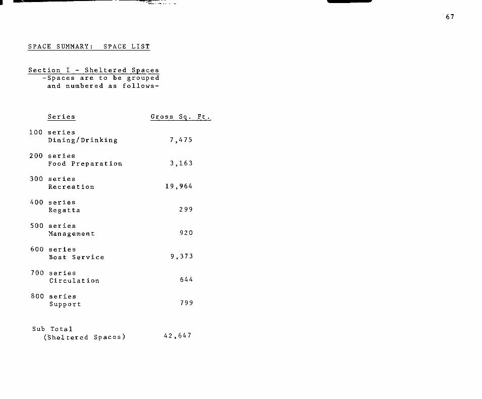
"^''•IW
67
SPACE SUMMARY: SPACE LIST
Section I - Sheltered Spaces -Spaces are to be grouped and numbered as follows-
Series Gross Sq. Ft
100 series Dining/Drinking 7,475
200 series Food Preparation 3,163
300 series Recreation 19,964
400 series Regatta 299
500 series Management 920
600 series Boat Service 9,373
700 series Circulation 644
800 series Support 799
Sub Total (Sheltered Spaces) 42,647

68
100 Series: Dining/Drinking
Series Sq. Ft
101 Main Dining Room 100 X 14 sq. ft./person 2 5% overflow
102-103 Private Dining 102 - 25 X 14 sq. ft./person 103 - 60 X 14 sq. ft./person
1,400
350 840
200 Series: Food Preparation
201 Kitchen 1/3 X Dining Space 2 ,446
202 Kitchen Storage (Dry Goods) .4 sq. ft./person served x 200 84
203 Kitchen Storage (Refrigerated) .3 sq. ft./person served x 700 60
104 Coctail Lounge 25 X 8 sq. ft./person 200
204 Kitchen Storage (Vegetable) .2 sq. ft./person served x 200 40
105 Bar and Grille 30 X 12 sq. ft./person 360
205 Bar Service 80
106 Ball Room 200 sq. ft./person 3,000
Net Square Footage 6,500 Net to Gross 975 Gross Square Footage 7,475
206 Bar Storage 40
Net Square Footage 2,750 Net to Gross 413 Gross Square Footage 3,173

69
300 Series: Recreation
Ser ies
301-302 Locker Room 90% membership x 14
sq. ft./person
301 Men's Locker Room = 75% Total
302 Women's Locker Room = 25% Total
Sq. Ft
3^780
1,-2 6 0
310 Weight Room
311 Games Room
5,040 312 Sailing/Tennis Pro Shop
400
200
300
Net Square Footage 17,-360 Net to Gross 2,604 Gross Square Footage 19,964
303 Women's Shower 40% peak load 36 X 10 sq. ft./person 360
400 Series: Regatta Organization
401 Committee Room 180
304 Men's Shower 30% peak load 81 X 10 sq. ft./person
305 Women's Restroom
810
100
402 Weather Room 80
Net Square Footage 260 Net to Gross 39 Gross Square Footage 2 99
306 Men's Restroom
307 Men's Sauna and Whirlpool
150
200
308 Women's Sauna and Whirlpool 200
500 Series: Management
501 General Manager
502-503 Accounting 2 X 100 sq. ft. ea,
200
200
309 Indoor Tennis 2 courts 9,600
504 Food Service 150

70
500 Series cont
505 Harbor Master
506 Rental Manager
Sq. Ft:
100
150
800 Series: Support
801 Men's Public Restroom 3 urinals 3 water closets 4 lavatories 180
Net Square Footage Net to Gross Gross Square Footage
800 120 920
802 Women's Public Restroom 5 water closets 4 lavatories 180
600 Series : Boat Service 803 Powder Room 100
601 Service Bay 2 boats + work space
602 Service Office
700 Series: Circulation
701 Lobby 355 (total occupancy) x
1.5 sq. ft./person
8,000
150
Net Square Footage 8,150 Net to Gross 1,223 Gross Square Footage 9,373
804 Laundry storage of linen
805 Sail Storage
806 Janitor Storage
75
300
80
Net Square Footage 695 Net to Gross 104 Gross Square Footage 799
533
702 Coat Room 80
Net Square Footage Net to Gross Gross Square Footage
613 31
644

71
Section II - Unsheltered Spaces -Spaces are to be grouped and numbered as follows-
Series
100 series Parking
200 series Boat Storage
300 series Games Room
Gross Sq. Ft
70,000
63,700
36,720
Sub Total (Unsheltered Spaces) 160,420

72
100 Series : Parkin S.
Series
101 Automobile only 150 spaces x 300 sq. ft./space
Sq- Ft.
45,000
302 Games Basketball
2 court s Shuffle Board Tennis
4 courts
4 ,200 520
28,800
102 Automobile and Trailer Overflow for Automobile (Mviy 50 spaces x 500 sq. ft./space 25 , 000
200 Series : Boat Storage
201 Wet Storage (slips) Adjusted to meet needs of individual boats (Activity Analysis)
Number required flexible according to harbor design
100 X 312 sq. ft./space average 31,200
202 Dry Storage 60 X 375 sq. ft./space Sheltered, possibly enclosed
22,500
300 Series:
301 Pool 1600 ft. 1600 ft.
Games
pool area lounging area 3,200

73
SPACE SUMMARY: SOURCES
Ramsey and Sleeper, Architectural Graphic Standard, (John Wiley and Sons, New York, 1970).
Joseph De Chiarra, Time Saver Standards for Building Types, (Mc Graw-Hill, New York et. al. 1973).
Interviews with:
Ken Abbott: Owner/Manager "Paddles n' Sails", sail boat distributorship and repairs, Lubbock Texas.
Mel Stuart: General Manager, Hillcrest Country Club, Lubbock Texas.
Case Studies

74
DETAILED SPACE LIST

75 iT
DETAILED SPACE LIST
Format Explanation
The following serves to establish
the working format for recording the
detailed space requirements for each
space presented in the Space Summary
Section of this chapter.
FACILITY NUMBER/DESCRIPTIVE TYPE
Area :
Function:
Occupancy :
Lighting:
Electrical:
Accoust ical:
Communication
Utilities:
Assignable floor area
Brief description of space function
Number of occupants where applicable
Lighting requirements per space
Electrical requirements per space
Accoustical requirements per space
Floor:
Walls :
Ceiling :
Use Frequency
Security:
Access :
Air Quality:
Furnishing and Equipment
Comments:
Floor materials, special loading conditions where applicable
Wall materials (special condit ions)
Ceiling height and/or materials
Times of use
Special security considerations where applicable
Desired proximities to other areas
Desired environmental condit ions
Type and number required for use of space
Special considerations, view, etc. per space

76
100 SERIES: DINING/DRINKING
101 - MAIN DINING ROOM
Walls
Area :
Function:
Occupancy
Lighting :
Electrical
Communication
Utilities
Accoust ies
Floor :
1,400 sq. ft. (additional 350 sq. ft. overflow)
To provide the primary facility for the majority of dining functions
Maximum 100 (25 additional in overflow), varies with meal type and service being provided
40 f.c. variable to adjust for desired atmosphere
Convenience outlets each wall, power outlets for service stations (refrigerator , etc . )
Telephone booths located adjacent to but out of site of space, 2 required
Water to service stations, waste disposal (sewer) to service stations
Block out noise from other spaces, noise generation limited to 45 db max.
Carpet, medium finish
Ceiling:
Use Frequency
Security:
Access:
Air Quality:
Furnishing and Equipment:
Medium finish, possible partition walls to close off portions of space not being used
9 ft. clearance, light finish
Often, various times each day
N/A
Access to other dining areas and kitchen area, access to cocktail lounge
Mechanically controlled heating and cooling
Table and chairs,seating for groups from 2-8 with emphasis on 2 Table: Graphic Standards
pg. 465 Chairs: Graphic Standards
pg. 463 Arrangement: Graphic
Standards pg. 30
5 service stations located throughout space, station for storage of silverware, dishes, 11 linen, condiments, etc. Approx. size 24" wide x 38" high

77
102-103 - PRIVATE DINING
Area :
T u n c t i; i> •
Function:
Occupancy:
Lighting:
Electrical:
Communication
Utilities:
Accoust ies
Floor :
Walls :
(102)-350 sq. ft. (103)-840 sq. ft.
Private parties, banquet, etc .
(102)-25 (103)-60
40 f.c. variable to adjust for desired atmosphere
Convenience outlets each wall, power outlet for refrigerator at service station
Adjacency to telephone boo ths
Water and sewer to service stations
Block out noises from other spaces, noise generation limited to 45 db maximum
Medium finish, carpet
Medium finish, folding (of other type partition walls to provide for possible combination of spaces)
Ceiling:
Use Frequency
Security :
Access :
Air Quality:
Furnishing and Equipment
Comments
Light finish, 9 ft. clearance
Infrequent, special oc-caislons, mostly on request of member
Secure when not in use
Access to lobby, access to other dining areas and kitchen area
Mechanically controlled heating and cooling
Tables and chairs, seating for groups of 4-8 with emphasis on 4 Tables: Graphic Standards
pg, 465 Chairs: Graphic Standards
pg. 463 Arrangements: Graphic
Standards pg. 30
Service Station: as in space No. 101, approx. dim. 8' x 30", accessible to one or both spaces 7' screen wall
View of lake, special attention to privacy aspect
Light
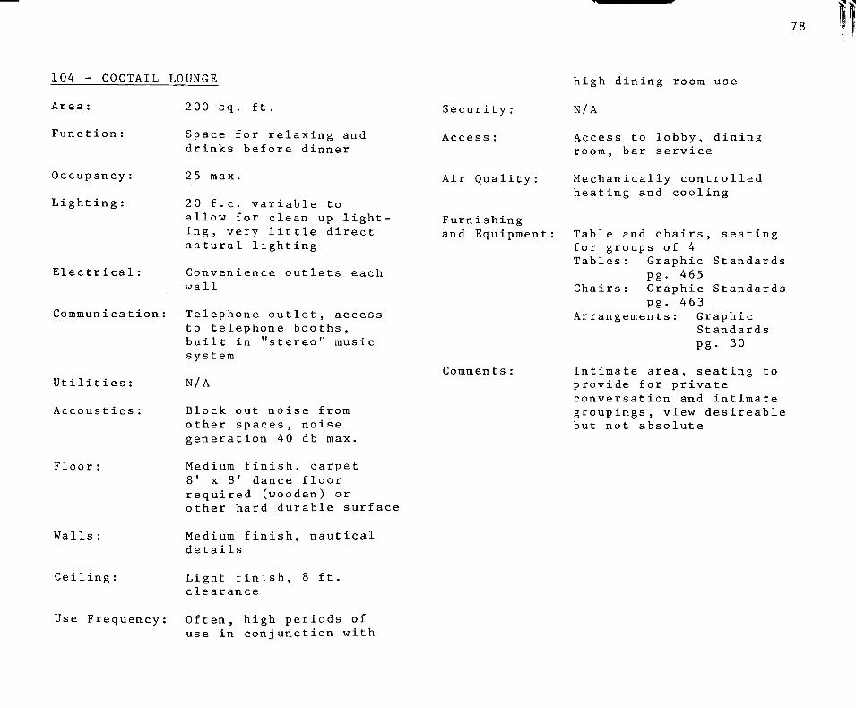
78
104 - COCTAIL LOUNGE
Area :
Function:
Occup ancy:
Lighting :
Electrical :
Communication
Ut H i t ies :
Accoust ies :
Floor :
Walls:
Ceiling:
Use Frequency
200 sq, ft.
Space for relaxing and drinks before dinner
2 5 max,
20 f,c. variable to allow for clean up lighting, very little direct natural lighting
Convenience outlets each wall
Telephone outlet, access to telephone booths, built in "stereo" music system
N/A
Block out noise from other spaces, noise generation 40 db max.
Medium finish, carpet 8' x 8' dance floor required (wooden) or other hard durable surface
Medium finish, nautical details
Light finish, clearance
ft .
Security :
Access :
Air Quality :
Furnishing and Equipment;
Comments
high dinirtg room use
N/A
Access to lobby, dining room, bar service
Mechanically controlled heating and cooling
Table and chairs, seating for groups of 4 Tables: Graphic Standards
pg. 465 Chairs: Graphic Standards
pg. 463 Arrangements: Graphic
Standards pg. 30
Intimate area, seating to provide for private conversation and intimate groupings, view desireable but not absolute
Often, high periods of use in conjunction with

79
105 - BAR AND GRILLE
Area :
Function:
Occupancy :
Lighting :
Electrical :
Communication
Utilities :
Accoust ies :
Floor:
Walls :
Ceiling :
Use Frequency
Security:
Access:
360 sq. ft.
Casual eating and drinking, fast food service
30 max.
40 f.c.
Convenience outlets each wall
Telephone, (private number)
N/A
Block out noise from other spaces, noise generation 50 db
Medium finish, indoor/ outdoor carpet
Medium finish
Light finish
Often
N/A
Outside access, access to dock area, access to food area
Air Quality:
Furnishing and Equipment
Comments
Mechanically controlled heating and cooling
Table and chairs, seating for groups of 4 Tables: Graphic Standards
pg. 465 Chairs: Graphic Standards
pg. 463 Arrangement: Graphic
Standards pg, 30
View of harbor area, pool area, high traffic space, materials & furnishings should be of durable mat erials Patron area only Bar Tender area allowed for in #205 bar service

10 1
106 - BALL ROOM
Area :
Funct ion :
Occupancy :
Lighting :
Electrical:
Communicat ion:
Utilities :
Accoust ies:
Floor:
Walls:
Ceiling:
Use Frequency
Security:
Access:
3 , 000 sq, ft,
Formal dances, rental to local organizations
200
40 f,c, variable to adjust for desired atmosphere
Convenience outlets each wall
N/A
N/A
Block out noise from other spaces, noise generation 50 db max.
Medium finish, carpet, small dance floor (wooden or other hard surface)
Medium finish
Light finish, 9 ft. clearance
Infrequent
Secure when not in use
Access to lobby, pool area (possibly)
Air Quality:
Furnishing and Equipment
Commen ts
Mechanically controlled heating and cooling
Seating for from 2-8, variable groupings Tables: Graphic Standards
pg. 465 Chairs: Graphic Standards
pg. 463
Stage area required, tables and chairs may be stored elsewhere or behind partition wall inside space

81
200 SERIES FOOD PREPARATION Access:
201 - KITCHEN
Area :
Function:
Occupancy :
Lighting :
Electrical :
Communication
Utilities :
Accoust ies :
Floor:
Ceiling:
Use Frequency
Security:
2 ,446 sq. ft.
Food preparation for all dining facilities
15
50 f.c.
Power outlets as required for equipment needs, convenience outlets
N/A
Water, waste disposal, garbage removal
Minimize transmission of noise created within
Light finish, easily cleaned, attractive and hygenic appearance tile up to 5 or 6 ft. , water resilent materials, 72% min. reflectivity
As walls, 10 ft. clearance
Often, daily
Authorized personel only
Air Quality:
Furnishing and Equipment
Access to dining rooms, storage, minimize separation from all dining areas, greatest accessibility to space No. 101, access to outside
Mechanically controlled heating and cooling, filter to remove foreign particles
1-4 oven general-purpose range 7 cu. ft. capacity and a total of 1,600 sq. in, boiling plates 1 open type bain-marie 2 griller-toasters with a total area of 800 sq. ft,
•2 steaming ovens ea. of 6 cu. ft. capacity 2 20 gal. vegatable boilers with steaming attachments •1 stockpot of 16 gal. with stand •1 2 deck pastry oven with area of 1,300 sq. in./deck •2 8ft. hot cupboards w/ heated tops, •2 cafe sets of 160 pt capacity with 2 gal. mild & coffee urns •1 coolroom, 250 cu. ft. •1 water heater 200 gal. with attachments •1 mixing machine, 30 qt . capacity with attachments •1 potato peeler, 28 lb.
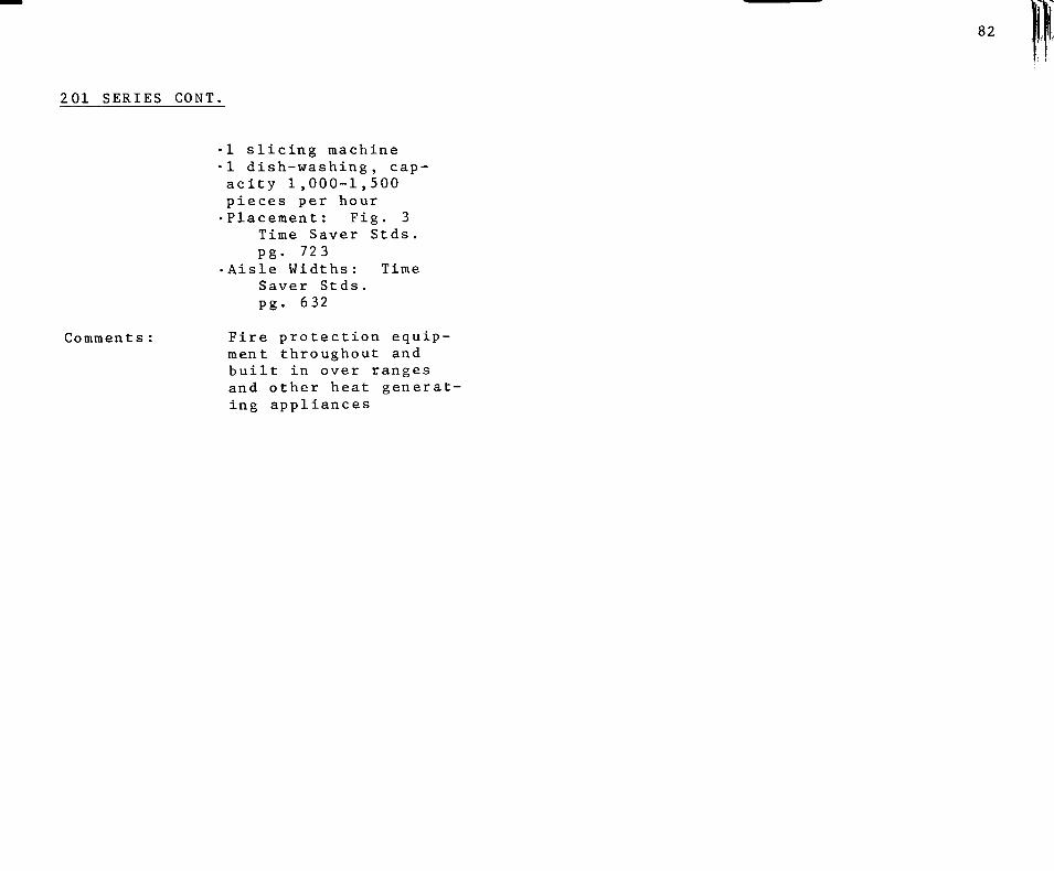
82
201 SERIES CONT.
1 slicing machine 1 dish-washing, capacity 1,000-1,500 pieces per hour •Placement: Fig. 3
Time Saver Stds, pg. 723
•Aisle Widths: Time Saver Stds. pg. 632
Comments Fire protection equipment throughout and built in over ranges and other heat generating appliances

83
202-204 - KITCHEN STORAGE (202) (203) (204)
DRY GOODS REFRIGERATED VEGETABLES
Air Quality:
Area :
Function :
Occupancy :
Light ing :
Electrical:
Communication
Utilities :
Accousties :
Floor :
Walls :
Ceiling :
Use Frequency
Security:
Access :
(202) 80 sq. ft. (203) 60 sq. ft, (204) 40 sq, ft.
Storage of food for kitchen use
None
10 f,c,
N/A
N/A
Floor drains in ea.
Contain noise generated within
Hard, durable, finished concrete
Durable
As walls
Continuous
Controlled access and egress
Access to receiving, food preparation
Furnishing and Equipment
Comments
(202) Unconditioned (203) Refrigerated as to food requirements, maintain 32° F temp, (204) Refrigerated as to food requirements, maintain temp , 350 F
range of 20-
Adjustable shelves and floor storage shelves
N/A

84
205 BAR SERVICE
Area :
Function
Occupancy:
Lighting:
Electrical
Communication
Utilities:
Accoust ies :
Floor :
80 sq. ft.
Service of alcholic drinks to Cocktail Lounge and Bar and Grille (possibly divide into separate spaces
1 or 2
20 f.c. down lighting, concentrated inside bar service area
Convenience outlets, power outlet for equipment, locate approx. 6' o.c.
N/A
Water, waste disposal
Block out noise from other spaces, noise generation 40 db max.
Water proof, non-slip surface
Security:
Access
Air Quality
Furnishing and Equipment
;. BAR
1:: .
Authorized personnel only
Access to served areas, dining area, bar storage
Mechanically controlled heating and cooling
Blender, drink metering equipment, sinks, miscellaneous small appliances. Bar and bar stools
I R !
8ASTEN0EFS AISLE
Qooe-CUIVCD TTPUi
STIAICHT TY»l-«Mi m witltMit rtMlt
A * r . M M c U *
1 J rH i • • ••4)
C C S>«t. o t - t * • • •
^ 1 t -v *-* ' J 'a , - t
1 » 1 J-0
Om. 1 C«
afl . , S-0 1 S
: 3 : :
1 LtHt <• u r ' 1 rg 1 -0 3 < <
I U<> M r
T l i ^ t H a c I M l . -< 'r> •
m <B It • -( -o J 3 :0
: t
= ( •, »
9 : t
•> ; I
0
Walls :
Ceiling:
Use Frequency
Medium finish, mirrors behind liquor bottles
Light finish
As Coctail Lounge and Bar and Grille
.CABINET OVER
^ P A C E FOR ' T CASH REG.
EZ3
BACK BAR
^ I ' lAlt OR STIF
BAR STOOL
• A l mCHTS
Source: Time Saver Stds. pg, 765

85
206 - BAR STORAGE
Area :
FunctIon:
Occupancy :
Lighting:
Electrical :
Communication:
Utilities :
Accoust ies :
Floor :
Walls :
Ceiling :
40 sq. ft .
Storage of liquor etc. for bar service area
N/A
10 f.c.
N/A
N/A
N/A
N/A
Resilient, water proof
Resilient
As walls
Use Frequency: Constant, liquor placed in storage every night and taken out every morning
Security:
Access
Air Quality:
Furnishing and Equipment
High, access by locked door only
Access to Bar Service Area
Unconditioned
Adjustable shelves.
shelf storage for individual bottles, floor storage for case quantities
Comments none
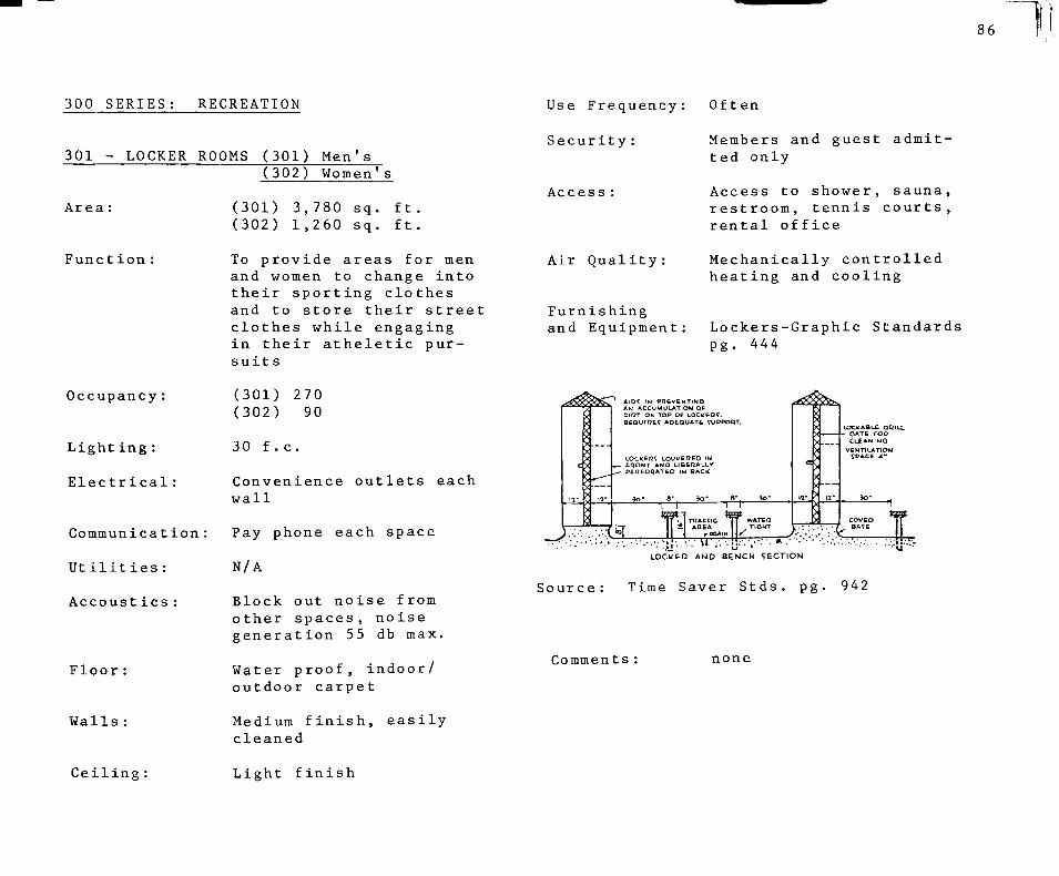
86
300 SERIES: RECREATION
301 - LOCKER ROOMS (301) Men's (302) Women's
Area
Function
Occupancy:
Lighting:
Electrical:
Communication:
Utilities:
Accoust ies:
Floor:
Walls:
(301) 3,780 sq. ft. (302) 1,260 sq. ft.
To provide areas for men and women to change Into their sporting clothes and to store their street clothes while engaging in their atheletic pursuits
(301) 270 (302) 90
30 f.c.
Convenience outlets each wall
Pay phone each space
N/A
Block out noise from other spaces, noise generation 55 db max.
Water proof, indoor/ outdoor carpet
Medium finish, easily cleaned
Use Frequency
Security:
Access :
Air Quality:
Furnishing and Equipment
Often
Members and guest admitted only
Access to shower, sauna, restroom, tennis courts, rental office
Mechanically controlled heating and cooling
Lockers-Graphic Standards pg. 444
A l D f IM P Q t V E M T I N O AM ACCUMULATION OF DifTT ON TOP OP L O C l f t Q ^ . DEQUII3C7 AOEOUATb TUPPOQT.
LOCKEFl? UOUVEflEO IM _ FQONT AMD L I B t i l A L L V
P C n P O I l A T E O IN BACk
-1—r -T—r TTJACCIC
AQEA /•OQAI
>-
•I
JS- >
LOClfABLC OQILL • OATE c o n
CLCAMrMG
^yA.::kZ LOCklEn AND BENCH SECTION
Source: Time Saver Stds. pg. 942
Comments: none
Ceiling: Light finish
Hi r,
87
303-304 MEN'S AND WOMEN'S SHOWER
Area :
Funct ion:
Occupancy :
Lighting :
Electrical:
Communicat ion
Utilities :
Accoust ies:
Floor :
Walls
(303) Women's Shower 460 sq. ft.
(304) Men's Shower 960 sq. ft.
Area for washing, bathing after atheletic activit ies
36 max.
30 f.c., heat lamps and incandescent lighting
Convenience outlets in dressing area at counter height
N/A
Hot and cold water, sewage and waste disposal
Block out noise from other spaces, noise generation 60 db max.
Non-slip, water proof, area drains, indoor/ outdoor carpet in toweling area, entire floor surface in "gang" shower area to be tiled as walls
Glazed ceramic tile, water resilient backing
Ceiling: As walls
Use Frequency: Often
Security:
Access:
Air Quality:
Furnishing and Equipment
Comments:
Entrance from locker room only
Access to locker room, laundry room, indirectly to pool area
Mechanically controlled heating and cooling, air dehumidifloat ion
(303) •6 "gang" showers
Graphic Standards pg. 35
,4 individual showers Graphic Standards pg, 35
.Drinking Fountain Graphic Standards pg. 598
(304) .12 "gang" showers
Graphic Standards pg. 35
.Drinking Fountains Graphic Standards pg. 598
"gang" shower heads to be 4 feet apart and 6 feet high in 304, 4 feet apart and 415 ft. high
88
305-306 - MEN'S AND WOMEN'S RESTROOM
Area
Function
Occupancy :
Lighting :
Electrical :
Communication:
Utilities :
Accousties :
Floor :
Walls:
Ceiling:
Use Frequency
Security:
(305) Women's 100 sq. ft.
(306) Men's 150 sq. ft.
Relief facilities for use of patrons in locker and shower rooms , and while engaged in athletic actIvit ies
varies
30 f.c.
Convenience outlets each wall, waterproof
N/A
Water, sewer, waste disposal
Noise generation 60 db max,
Non-slip, water proof, area drains, tile or similar finish
Glazed ceramic tile, water resilient backing
As walls
Intermit tent
N/A
Access :
Air Quality:
Furnishing and Equipment
Comments
Access to Locker Room, Shower Room
Mechanically controlled heating and cooling, vent fans through roof
(305) 5 toilets with partitions
Graphic Standards pg. 596
4 lavatories Graphic Standards pg. 595
Misc. Accessories Graphic Standards pg. 420-421
4 mirrors Graphic Standards pg. 420
(303) 3 toilets
Graphic Standards pg 596
4 Urinals Graphic Standards pg. 596
Misc. Accessories Graphic Standards pg. 420-421
4 lavatories Graphic Standards pg. 35
4 mirrors Graphic Standards pg. 420
Direct access should be afforded from Locker/ Shower Room and from outside (pool area)
89
307-308 - SAUNA. WHIRLPOOL Furnishing
and Equipment: Benches: ^^^^' 200 sq. ft. Graphic Standards
pg. 469 Function: Relaxation after strenous Whirlpool, 9' circular
exer cise Sauna, 10 x 6
Occupancy: Varies Comments: Plants and other decorations to enhance relaxa-
Lighting: 30 f.c. tion atmosphere Two units - one for male
Electrical: Power outlets for eqip- use and one for female ment use
Communication: N/A
Utilities: Water, sewage disposal
Accoustics : Block out noise from
other spaces, noise generation 65 db max.
Floor: Redwood of other water
resilient materials
Walls: As floors
Ceiling: As floors
Use Frequency: Varies
Security : N/A
Access: Access to respective locker room
Air Quality: Mechanically controlled, (largely maintained by apparatus within)

90
309 - INDOOR TENNIS
Area :
Funct ion :
Occupancy:
Lighting :
Electrical:
Communicat ion
Ut H i t ies :
Accoustics :
Floor :
Walls:
Ceiling:
9 ,600 sq. ft ,
Protected area for tennis
8-10
Two 2,000 or 1,500 watt projectors on 40' poles at center court
Convenience outlets for court maintenance equipment
N/A
N/A
N/A
Concrete with rubberized playing surface
Light finish, allow for "practice" walls (hard smooth surface with 4" paint stripe at net height)
Light finish, shylights for required clearances, see Graphic Standards pg. 61
Security:
Access
Air Quality:
Furnishing and Equipment:
Comments
Access only after checking in at reservation desk (rental sales area)
Access to Locker Rooms, Pro Shop
Mechanically controlled heating and cooling maintained at 75°
For court layout (2 courts) see Graphic Standards pg. 61
Possible removable roof system Phase I design as open-air facility, enclose in Phase II
Use Frequency: Daily

91
310 - WEIGHT ROOM
Area :
FunctIon:
Occupancy:
Lighting:
Electrical:
Communication
Utilities:
Accoustics:
Floor:
Walls :
Ceiling:
400 sq. ft.
Space for use of "nautilus" type weight equipment
Varies
50 f.c.
Convenience outlets each wall
Access to pay phone
Chilled water fountain
Block out noise from other spaces, noise generation 50 db max.
Medium finish, indoor/ outdoor carpet
Mirror panels
Light Finish
Furnishing and Equipment
Use Frequency: Infrequent
Security:
Access :
Air Quality
N/A
Access to Locker Rooms, Whirlpool, Sauna
Mechanically controlled heating and cooling
Comments
Water fountain Graphic Standards pg. 598
"Nautilus" weight equipment free weights Graphic Standards pg. 492
Isolate space for noise control but allow for observation from outside of space
92
311 GAMES ROOM
Area :
Funct ion :
Occupancy :
Lighting :
Electrical :
Communication :
Ut H i t ies :
Accoust ies:
Floor:
Walls :
Ceiling :
Use Frequency:
Security:
Access:
200 sq, ft.
Electronic "video" games, card tables, etc. for younger club members
Varies
10 f.c. , down lighting for table games
Power outlets for video machines, convenience outlets each wall
Access to pay phone
N/A
Isolate noise produced by machines, generation 40 db max.
Medium finish, carpet
Medium finish
Light finish
Constant
N/A
Access to outdoors, isolate from passive activlt ies
Air Quality:
Furnishing and Equipment
Comments
Mechanically controlled heating and cooling
Video Games, approx. 2' X 2' Tables: Graphic Standards
pg. 465 Chairs: Graphic Stand
ards pg. 463
Decorate to suit younger memb ers

93
312 - SAILING AND TENNIS PJRO SHOP
Area :
Funct ion :
Occupancy:
Light ing:
Electrical:
Communication;
Utilities :
Accoustics :
Floor:
Walls:
Ceiling:
Use Frequency
Security:
300 sq. ft.
Sales of sailing and tennis equipment, rental of small sailboats, tennis court reservations
one
50 f.c., spot/accent lighting, showcase lighting
Ginvenience outlets each wall
Telephone
N/A
Block out noise from other spaces, generation 50 db
Medium finish, carpet
Medium finish, display racks
Light finish
8-5 or similar business hours
Totally secure when closed, visual control over access and egress when open
Access:
Air Quality:
Furnishing and Equipment
Commen ts
Access to tennis courts, indirect access to lobby
Mechanically controlled heating and cooling
Display cases, cash register stands, scattered seating
Space must be comfortable and should be decorated in a nautical motif

94
400 SERIES: REGATTA ORGANIZATION
401 - COMMITTEE ROOM
Area :
Function:
Occupancy :
Lighting :
Electrical:
Communication
Utilities:
Accoustics:
Floor:
Walls:
Ceiling:
180 sq. ft.
To provide room for holding of skippers meetings and regatta organizat ion
Varies with side of regatta
50 f.c.
Convenience outlets each wall
N/A
Access to chilled water fountain
Block out noise from other spaces, generation 35 db max.
Medium finish, carpet
Medium finish
Light finish
Access :
Air Quality :
Furnishing and Equipment
Comments
Isolated from most other parts of club access to weather room
Mechanically controlled heating and cooling
Folding Tables: Graphic Standards pg. 470
Folding chairs: Graphic Standards pg. 478
Chalkboard - 4' x 6'
View of lake
Use Frequency: Infrequent, concurrent with regatta's
Security: none

95
500 SERIES: OFFICE PERSONEL
501 - GENERAL MANAGER
Area :
Funct ion:
Occupancy :
Lighting:
Electrical:
Communication
Utilities:
Accoustics:
Floor :
Walls :
Ceiling:
Use Frequency
Security:
Access:
200 sq. ft.
Office for General Manager operations
50 f.c., indirect, minimal glare
Convenience outlets each wall, outlet at desk for small adding machine
Telephone
N/A
Block out noise from other spaces, noise generation 35 db max.
Medium finish, carpet
Medium finish
Light finish
: Daily, 8-5 or normal business hours
Lockable
Access to lobby
Air Quality
Furnishing and Equipment
Comments:
Mechanically controlled heating and cooling
Desk: Graphic Standards pg. 473
Chair: Graphic Standards pg. 463
Bookshelves: Graphic Standards pg. 468
Placement in overall design should be so as to provide ease of access from view of harbor area

96
502-503 - ACCOUNTING
Area :
Function :
Occupancy :
Light ing :
Electrical :
Communicat ion
Utilities :
Accoustics :
Floor :
Walls :
Ceiling :
100 sq. ft.
General Accounting Activities membership rosters etc.
1 ea .
150 f.c., indirect, minimal glare
Power outlet for adding machines, convenience outlets each wall
Telephone
N/A
Block out noise from other space, noise generation 35 db max.
Medium finish, carpet
Medium finish
Light Finish
Air Quality
Furnishing and Equipment
Comments:
Mechanically controlled heating and cooling
Filing cabinets: Graphic Standards pg, 468
Other as space 501
None
Use Frequency: Daily, 8-5 or normal office hours
Security:
Access :
Lockable
Access to each other, indirectly to General Manager
97
504 - FOOD SERVICE MANAGER
Area :
Funct ion:
Occupancy :
Lighting :
Electrical
Utilit ies :
Accoust ies
Floor :
Walls :
Ceiling:
150 sq, ft.
Keeping records of food shipments, catering details, meal planning (chef's office)
50 f.c., indirect, minimal glare
Convenience outlets each wall
Communication: Telephone
N/A
Block out noise from other spaces (kitchen), noise generated 35db max.
Medium finish
Medium finish
Light finish
Use Frequency: Daily, 8-5 or normal office hours plus as needed
Security:
Access:
Lockable
Access to kitchen, receiving and storage area
Air Quality:
Furnishing and Equipment
Comments:
Mechanically controlled heating and cooling
As space #502, 503
Visual supervision of kitchen area Visual supervision of loading and receiving area
98
505 - HARBOR MASTER
Area :
Function
Occupancy:
LightIng :
Electrical
Utilities :
Accoustics
Floor:
Walls:
Ceiling:
100 sq. ft.
Coordination of Harbor/ Marina information, maintenance of harbor area
50 f.c., indirect, minimal glare
Convenience outlets each wall
Communication: Telephone
N/S
Block out noise from other spaces, noise generation 35 db max.
Medium finish, no carpet
Medium finish
Light finish
Use Frequency: Daily, 8-5 or normal office hours
Security
Access :
Lockable
Access to harbor area
Air Quality: Mechanically controlled heating and cooling
Furnishing and Equipment: As space #501
Commen ts View of harbor

99
506 - RENTAL MANAGER
Area :
Function :
Occupancy :
Lighting :
Electrical
Utilities:
Accoustics:
Floor :
Walls :
Ceiling:
Use Frequency
SecurIty :
Access :
Air Quality:
150 sq. ft.
Control of boat storage space rentals
50 f.c., indirect, suitable for reading/writing task
Convenience outlets each wall
Communication: Telephone
N/A
Block out noise from other spaces, noise generation 35 db max.
Medium finish, carpet
Medium finish
Light finish
Daily 8-5 or normal office hours
Lockable
Access to lobby
Mechanically controlled heating and cooling
Furnishing and Equipment:
Comments:
As space 502, 503
Possibly combine with Harbor Master #505

100
600 SERIES: BOAT SERVICE Air Quality: Mechanically heated
601 - SERVICE BAY
Area :
Function:
Occupancy:
Lighting:
Electrical:
Communication;
Utilities:
Accoust ies:
Floor :
Walls :
Ceiling:
Use Frequency
Security :
Access :
8,000 sq. ft .
Area for general repair of large and small boats
Varies
50 f.c.
Convenience outlets at benches, extension outlets on retractable chords for work area
Telephone
Water , sewer
N/A
Concrete
Medium finish
30' clearance
Sporadic
Lockhle
Direct access to water access to water closet, lavatory
Furnishing and Equipment
Comments
Overhead bridge crane Peripheral work benches 30" high
Air compressor and hoses for pneumatic tools
Jib Crane See Appendix B
Space provided for carpenters, electronics, engine repairs, fiberglass repair, sail repair

101
602 - SERVICE OFFICE
Area :
Function:
Occupancy :
Lighting:
Electrical:
Communication:
Utilities:
Accoust ies:
Floor:
Walls :
Ceiling:
Use Frequency
Security:
Access:
Air Quality :
150 sq. ft.
Control and supervision of service department
1
30 f.c., indirect, minimal glare
Convenience outlets each wall
Telephone
N/A
Block out noise from service bay
Durable, indoor/out door carpet
Medium finish
Light finish
Daily 8-5 or normal business hours
Secure from service bay
Access from service bay, access from dock area
Mechanically controlled heating and cooling
Furnishing and Equipment
Comments
As space #505 Provide for access to water closet, lavatory
Visual access to service bay
102
700 SERIES CIRCULATION
701 - LOBBY
Area :
Function:
Occupancy:
Lighting:
Electrical:
Communication:
Utilities:
Accoustics:
Floor:
Walls:
Ceiling:
Use Frequency
Security:
Access :
533 sq. ft.
Gathering point, orientation for club activities, central circulation area
Varies
20 f.c.
Convenience outlets each wal 1
Pay telephone, 2 booths (also accessible from main dining
N/A
Block out noise from other spaces, noise generation 35 db max.
Medium finish, carpet
Medium finish
Light finish
Constant
N/A
Access to Coctail Lounge, Main and Private Dining Rooms, Offices
Air Quality
Furnishing and Equlpmen t;
Comments:
Mechanically controlled heating and cooling
Couches: Graphic Standards p g. 4 6 6
Chairs: Graphic Standards pg. 465
Tables: Graphic Standards pg. 468
Lamps : Graphic Standards pg. 469
Bulletin area approx. 6' X 8' (cork or similar material)
Drinking fountain Graphic Standards pg. 598
This area is the first encountered by members and prospective members and as such should have the most elaborate furnishings and detailings. A view of the lake is also recommended, perhaps through other spaces.
103
702 - COAT ROOM
Area :
Funct ion:
Occupancy:
Lighting:
Electrical:
Utilities :
Accoust ies :
Floor:
Walls :
Ceiling :
Use Frequency
Security :
Access :
80 sq. ft .
Storage of heavy outer coats etc. while patrons are using club facilities
none
10 f.c.
N/A
N/A
N/A
Medium finish, carpet
Medium finish
Light finish
Varies
Total visual access from lobby area
Access to lobby, adjacent to restrooms (801-802)
Air Quality: Unconditioned
Furnishing and Equipment Coat and hat racks:
Graphic Standards pg. 479
Comments: none
104
800 SERIES SUPPORT FACILITIES
801-802 - (801) (802)
Men's Public Restroom Women's Public Restroom
Area :
Funct ion:
Occupancy:
Lighting:
Electrical:
Communication:
Utilities:
Accoust ies :
Floor :
Walls :
Ceiling:
Use Frequency :
Security:
Access :
180 sq. ft. ea,
Provide relier facilities for general use
Varies
30 f,c.
Convenience outlets each wall, water proof
N/A
Water, waste disposal, sewer
Block out noise from other spaces, noise generation 40 db max.
Easily cleaned, tile medium finish
As floor, medium finish
Light finish
Intermit tent
None
Access to lobby, indirectly to Main Dining Room, and centrally located in facility
Air Quality:
Furnishing and Equipment:
Mechanically controlled heating and cooling, vent fan through roof
Comments:
(801) • 3 urinals
Graphic St pg. 596
.3 water clos Graphic St pg. 596
• 4 lavatories Graphic St pg. 595
.4 mirrors Graphic St pg. 420
•Paper towel Graphic St pg. 420
(802) . 5 water clos
Graphic St pg. 596
• 4 lavatories Graphic St pg. 595
• 4 mirrors Graphic St pg. 595
•Paper towel Graphic St pg. 420
None
andards
ets andards
andards
andards
holder andards
ets andards
andards
andards
holder andards

a 05
803 - POWDER ROOM
Area :
Function:
Occupancy:
Lighting:
Electrical:
Communication:
Ut H i t ies :
Accoust ies:
Floor :
Walls:
Ceiling:
100 sq, ft.
Space for ladies to touch up make-up, rest, etc,
Varies
50 f,c.
Convenience outlets at counter height
N/A
N/A
Block out noise from o ther spaces
Medium finish, carpet
Medium finish
Light finish
Furnishing and Equipment
Use Frequency: Intermittent
Security:
Access :
Air Quality :
N/A
Access to Ladies Restroom #802 access to lobby
Mechanically controlled heating and cooling
Comments:
Counter (dressing table) 30" high, with marble top
Mirror behind counter Couch: Graphic Standards
pg. 466
none

^106
804 - LAUNDRY
Area :
Function:
Occupancy:
Lighting:
Electrical:
Communication:
Utilities:
Accoustics:
Floor:
Walls:
Ceiling:
Use Frequency
Security :
Access :
Air Quality :
75 sq. ft .
Cleaning and storage of house linens
Varies
30 f.c.
Power outlets for washer (110 V.) and dryer (220 V. )
N/A
Water, sewer
Contain noise created within
Water proof, medium finish, tile
Light finish
Light finish
Daily
Lockable
Indirect access to Locker Room and Dining Areas
Mechanically vented (no supply)
Furnishing and Equipment:
Comments:
Washer/Dryer combination Graphic Standards
pg. 426 Shelves for linen storage
15" high X 18" deep
none

107
805 - SAIL STORAGE Comments
Area :
Function:
Occup ancy:
Lighting:
Electrical:
Communication:
Utilities:
Accoust ies:
Floor:
Walls :
Ceiling :
Use Frequency:
Security:
Access :
Air Quality:
300 sq. ft.
Storage of club owned small boat sails
N/A
30 f.c.
Convenience outlets each wall
N/A
N/A
Absorb noises created within
Concrete
As floors
Light finish, no finish materials
Intermit tant
Authorized personel only
Access to Rental Manager Office, boat storage area
Uncondit ioned
Double check clearances for access and egress of 15' masts (maximum length)
Furnishing and Equipment: Storage racks suspended
from ceiling, 15' long
108
806 - JANITOR STORAGE
Area :
Funct ion:
Occupancy:
Lighting:
Electrical:
Communication
Ut H i t ies :
Accoust ies :
Floor :
Walls :
Ceiling :
Use Frequency
Security :
Access :
Air Quality :
Furnishing and Equipment:
80 sq. ft.
Storage of Janitorial supplies, equipment
N/A
40 f.c.
Convenience outlet one wall
N/A
Water, sewage
Absorb noises created within
Concrete, floor drain
Concrete
Unfinished
Intermit tent
Controlled access
Centrally located in facility
Unconditioned
Sink
Graphic Standards pg. 595
Storage shelves for cleaning needs
Comments none

1(
DETAILED SPACE LIST: SOURCES
Ramsey and Sleeper, Architectural Graphic Standards, (John Wiley and Sons, New York, 1970) .
Joseph De Chiarra, Time Saver Standards for Building Types, (Mc Graw-Hill, New York et. si., 1973).
Norman C. Harris, Modern Air Conditioning Practice, 2nd ed. (Mc Graw-Hill, New York et, al,, 1974).
John Fuller, Chef's Manual of Kitchen Management, (B,T, Batsford Ltd,, London, 1962).

1 1 0
SYSTEMS PERFORMANCE

I l l
SYSTEMS PERFORMANCE
The following section deals with
the systems to be incorporated by the
designer in his solution. Particular
aspects are enumerated in an effort
to call special attention to design
requirements which are unique or not
standard operating procedure. For this
reason standards of common practice
will go unmentioned. This, in no way
frees the designer from his responsibi
lity to follow these standards,
H.V,A.C.
erature range of 68 -73 F with relative humidity of approx. 50% except where otherwise noted
. System will incorporate individual zoning method whereby solar heat gain and heat loss will be compensated for In system heating and cooling load
. Individual rooftop or central package units may be used. If central unit system is used, equipment space must be isolated from passive, quiet areas, (ie. dining, etc.)
Structural
All units are to be mounted on rubber pads or other vibration absorbing material
Flexible connections to be used throughout
Ducts to be lined inside and out for noise reduction
Selection of Grilles and Registers shall be made so as to limit noise (allowable N.C, = 35 db
•System design will maintain temp-
• Human scale shall pervail in choice of materials and system selection
•Certain spaces require uninterupted, column free, solutions, these are Dining Room, Ball Room, and Indoor Tennis
.Structural system shall be designed to support a minimum live load of 100 Ib/sq, ft, except where required to provide for heavier loads by the Uniform Building Code and/of Appendix "C",
Electical
110 V, sevlce shall be provide to each convenience outlet
All outlets located in places of possible water contact will be equipped with waterproof covers
Circuit breakers will be used as opposed to fuses and breaker panel will be located in Janitor Storage space #806

112
Lighting
.Lighting system will be designed to provide for illumination as stated in Detailed Space List.
.Ballast for flourescent light fixtures shall be chosen with an attempt to minimize noise
.Ceiling reflectance will be 80% minimum in all spaces where a "light" finish is specified
.Wall reflectance will be 30% except in kitchen where 50% minimum Is required
.Floor reflactance will be 20%
.Lighting will be controlled by variable "dimmer" switches and shading devices incorporated to control adverse glare conditions
.Security Lighting will be installed on site. Pathways, parking lots, and boat docks will be illuminated at rate of 5 f.c.
.Security lighting will not produce harmfull effects in residences nearby ie. glare etc.
.Security lighting will be controlled by photo-electric cells
Accoust ies
•Materials and finishes shall be designed to supress background noise which shall not exceed an average of 40 db throughout the facility.
Communicat ion
for spaces as follows.
General Manager Retail Sales Rental Manager Kitchen Management Harbor Management Boat Service Toll Phone Installations
•An Interdepartmental Communication Systems will be installed in conjunction with telephone service
Transportation
.parking lots will be located so as to separate pedestrain and vehicular traf fie
•Lots for storage of car and trailor combinations will be located immediately adjacent to ramps, Jib-Crane Instalatlons etc.
.Access to Jlb-Crane and boat ramps will not be obstructed in any way
.Access to kitchen for deliveries and waste pick-up will be screened from general view
Codes, Ordinances, Regulations
•All design solutions will comply with the latest edition of the Uniform Building Code
•Application for zoning will be made in accordance with City of Azle "working notes" (Appendix "C")
Separate listings will be provided
113
Life Safeti
•Exists will be provided in accordance wxth uniform building code regulations
•Heat activated sprinkler systems will be installed throughout
Boat Handling
•See Appendix "B"

1 1 4
COST ANALYSIS

115
COST ANALYSIS
In order to make such a project
feasible from the investor's standpoint
construction phasing is necessary.
Certain facilities are considered as
indispenslble to a minimal operation,
these are:
.Lounge •Cocktail Lounge •Main Dining Room •Ball Room • Lobby •Men's and Women's Toilets •Powder Room • Storage • Check Room •Men's and Women's Locker Room .Men's and Women's Shower .Men's and Women's Toilets .Pro Shop .Bar and Grille
Other facilities may be added to this
"core" through proper expansion planning.
These are:
.Private Dining and Party Rooms
• Card Rooms .Porches and Terraces .Steam Room
Phasing of project construction
shall pursue these established guidelines
Consideration should be given to this
phasing in designing the Yacht Club.
However, emphasis should be placed on
designing the entire facility.
Building Construction Cost
Phase I
Dining
Main Dining, Ball Room, Coctail Lounge, Kitchen, Bar Service
"'•' Building Type: Restaurant
Gross Sq. Ft. 5,897 sq. ft.
Uniti^Gost $69.75/sq. ft.
Cost $$599,641
Retail
Games, Pro Shop
Building Type: Retail Stores
Gross Sq. Ft. 575 sq. ft.
Unit Shop $36.10/sq. ft.
Cost $20,758

116
Toilets/Laundry
Men's and Women's restroom, laundry
Building Type: Swimming Pools
Gross Sq. ft. 788 sq. ft.
Unit Cost $95.15/sq. ft
Cost $74,978
Dressing Men's and Women's Locker Rooms/Showers
Building Type: Swimming Pool
Gross sq. ft. 7,124 sq. ft.
Unit Cost $38.95/sq. ft.
Cost $278,181
Storage Kitchen Storage, Bar Storage, Service Bay, Sail Storage, Janito Storage
Building Type: Warehouse
Gross sq. ft. 9,895 sq. ft.
Unit Cost $16.90/sq. ft.
Cost $167,226
Office Manager, Accounting, Harbor Master, Food Service, Rental Manager, Service Manager, Committee Room, Weather Room, Lobby, Coat Room, Powder Room
Building Type: Office
Gross sq. ft. 2,212 sq. ft.
Unit Cost $55,.90/dq, ft
Cost $123,651
Phase I - Construction Cost Total
Cost Gross sq, ft. Cost/sq . :Tf t .
$ 1 , 2 6 4 , 4 3 5 $ 2 9 , 2 0 9 $ 4 3 . 2 9
Phase II
Dining
Private Dining Rooms, Bar and Grille
Building Type: Restaurant
Gross sq. ft. 1,783 sq. ft.
Unit Cost $69.75/sq. ft.
Cost $124,364
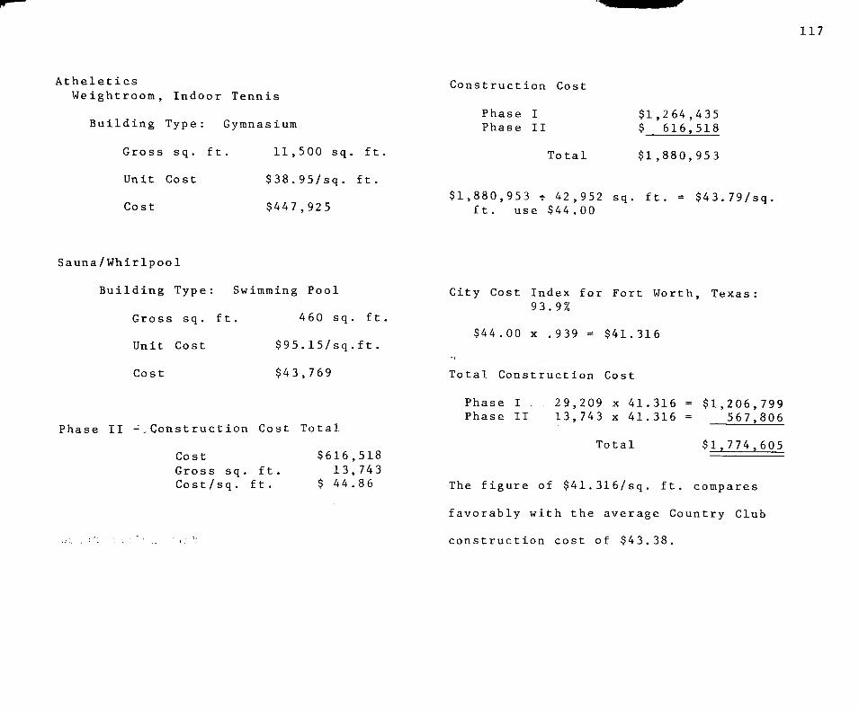
117
Atheleties
Weightroom, Indoor Tennis
Building Type: Gymnasium
Gross sq. ft. 11,500 sq. ft
Unit Cost $38.95/sq. ft.
Cost $447,925
Construction Cost
Phase I Phase II
T o t a l
$ 1 , 2 6 4 , 4 3 5 $ 6 1 6 , 5 1 8
$ 1 , 8 8 0 , 9 5 3
$1,880,953 - 42,952 sq. ft. = $43.79/sq ft. use $44.00
Sauna/Whirlpool
Building Type: Swimming Pool
Gross sq. ft. 460 sq. ft
Unit Cost $95,15/sq,ft.
Cost $43,769
Phase II -.Const ruction Cost Total
Cost Gross sq, ft Cost/sq, ft.
$616,518 13,743
$ 44,86
City Cost Index for Fort Worth, Texas 93.9%
$44.00 X .939 = $41,316
Total Construction Cost
Phase I 29,209 x 41,316 Phase II 13,743 x 41,316
Total
$1,206,799 567,806
$1,774.605
The figure of $41,316/sq, ft, compares
favorably with the average Country Club
construction cost of $43,38,
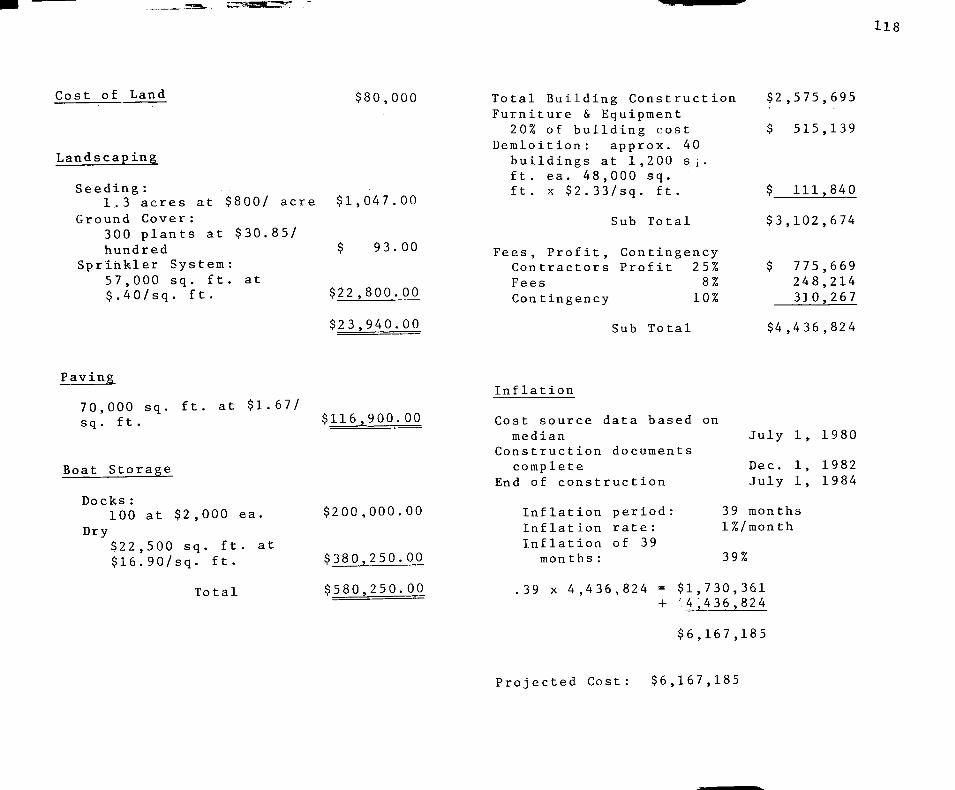
118
Cost of Land $80,000
Landscaping
Seeding:
1.3 acres at $800/ acre $1,047,00 Ground Cover:
300 plants at $30,85/ hundred $ 93,00
Sprinkler System: 57,000 sq. ft. at $.40/sq . ft .
$22,800.00
$23,940.00
Total Building Construction Furniture & Equipment
20% of building cost Demloltion: approx. 40
buildings at 1,200 Sj. ft. ea. 48,000 sq. ft . X $2.33/sq, ft ,
Sub Total
Fees, Profit, Contingency Contractors Profit 25% Fees 8% Contingency 10%
Sub Total
$2,575,695
$ 515,139
$ 111,840
$3,102,674
$ 775,669 248,214 310,267
$4,436,824
Paving
70,000 sq. ft. at $1.67/ sq. ft.
Boat Storage
Docks: 100 at $2,000 ea.
Dry $22,500 sq. ft. at $16.90/sq. ft.
Total
$116.900.00
$200 ,000.00
$380.250.00
$580.250.00
Inflation
Cost source data based on median
Construction documents complete
End of construction
Inflation period: Inflation rate: Inflation of 39
months:
July 1, 1980
Dec. 1, 1982 July 1, 1984
39 months 1%/month
39%
39 X 4,436,824 = $1,730,361 + 4.436,824
$6,167,185
Projected Cost: $6,167,185

Money Available
119
400 memberships at $500.00 ea.
average initiation
400 membership dues at $50/month
$200,000
$ 20,000
Income from Dining Room and Bar facilities (aprox. equal to dues) $ 20,000
Approximate income = $40,000/month
Monthly income equals - 6.6% of projected cost

COST ANALYSIS: SOURCE
12 0 J O
Robert Snow Meant? Pn Ti,.n-ij. ^ ' ^^i^^^i^i^-e^illtruction^os^^^ (Kingston. Mass, 1981)

CASE STUDIES
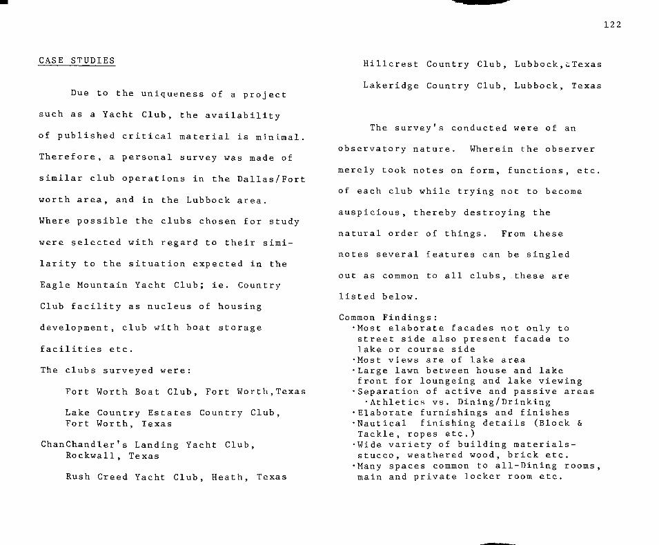
122
CASE STUDIES
Due to the uniqueness of a project
such as a Yacht Club, the availability
of published critical material is minimal.
Therefore, a personal survey was made of
similar club operations in the Dallas/Fort
worth area, and in the Lubbock area.
Where possible the clubs chosen for study
were selected with regard to their simi
larity to the situation expected in the
Eagle Mountain Yacht Club; ie. Country
Club facility as nucleus of housing
development, club with boat storage
facilities etc.
The clubs surveyed were:
Fort Worth Boat Club, Fort Worth,Texas
Lake Country Estates Country Club, Fort Worth, Texas
ChanChandler's Landing Yacht Glub, Rockwall, Texas
Rush Creed Yacht Club, Heath, Texas
Hillcrest Country Club, Lubbock, i. Texas
Lakeridge Country Club, Lubbock, Texas
The survey's conducted were of an
observatory nature. Wherein the observer
merely took notes on form, functions, etc.
of each club while trying not to become
auspicious, thereby destroying the
natural order of things. From these
notes several features can be singled
out as common to all clubs, these are
listed below.
Common Findings: •Most elaborate facades not only to street side also present facade to lake or course side •Most views are of lake area •Large lawn between house and lake front for loungeing and lake viewing •Separation of active and passive areas
•Athletics vs. Dining/Drinking •Elaborate furnishings and finishes •Nautical finishing details (Block & Tackle, ropes etc.) •Wide variety of building materials-stucco, weathered wood, brick etc. •Many spaces common to all-Dining rooms, main and private locker room etc.

Chandler's Landing Yacht Glub in
Rockwell, Texas is an AIA award wining
project and as such deserves special
attention. The great degree of simi
larity of purpose between it and
E.M.L.Y.C. also enhances it's Import
ance. The high points of the informa
tion gained from the survey are listed
below.
Chandler's Landing Yacht Club -A.I.A. Design Award Winner early 70's -Same project scope as E.M.L.Y.C.
-Yacht Club, Marina, Townhouse, Condominiums etc.
-Form *Marina, Yacht Club, Townhouses, located along shoreling -Private home further inland
*Marina, Yacht Club, Townhouses designed to complement each other through form and materials
-Houses (private) had no design restrictions, incongruity somewhat distracting *Landscaping and equipment also contained nautical atmosphere
123
Function -Separation of active, passive areas -Terraces, patios used to afford
best views of lake -People pleased with overall per
formace of club

APPENDIX A
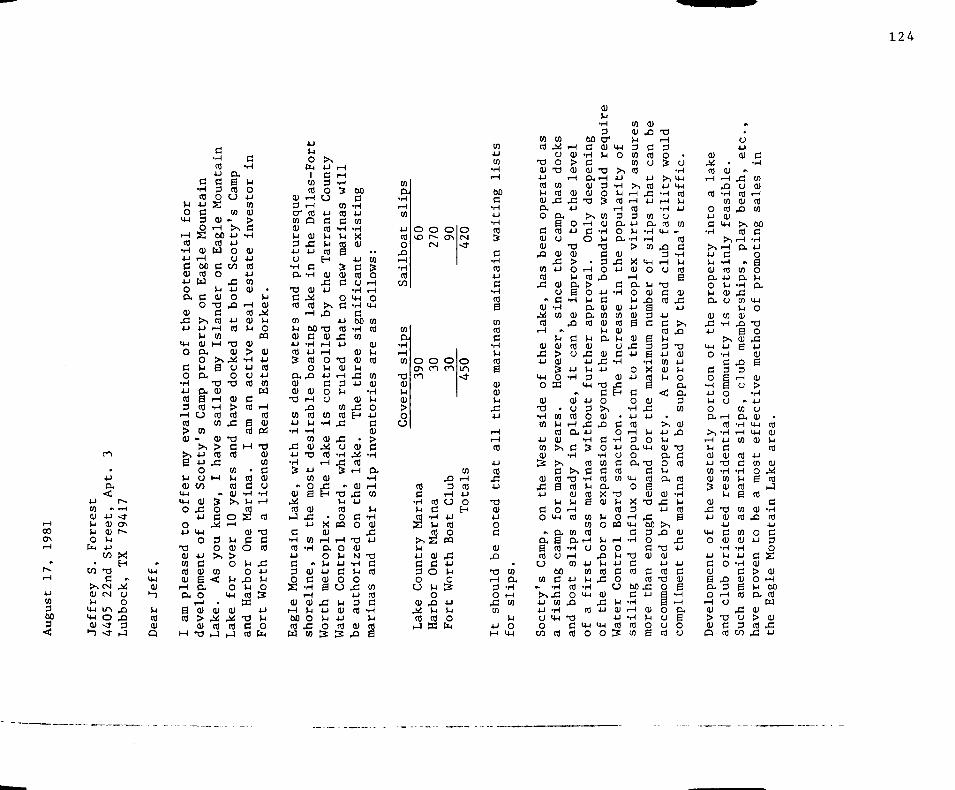
124
1-1 0 0 CJN 1-1
^ r~-i H
4-1 to 3 60 3 <
u tn <u 4
u o
b
, tn
tn
• 4J D.
< •» 4-1
<u a) u 4-1 CO
•o C
> > C N V u
>4-l 14-1
0)
>->
CSI
U-1 O •<r ~d-
r^ ,-H
-* o\ r-»
X H
•v J»i O o
X X 3
hJ
^ 14-1
<4-4
<U
>-> U rt lU
Q
for
r H rt
• H 4-1
c d) 4J
o CL
OJ
X u y-i
o c o
• H 4J CO
3 1-1
« > (U
>s
e u d)
H-l I M
o o 4J
-a tu en rt cu
i H
o. B CO
M
Mountain
igle Mounta:
CD
1—1 60 C rt o u
M C CU O TS
C >> rt 4J i-H 1-1 to
cu M a.
y's Camp
nvestor in
4-1 M-l 4J o cu O 4J
CO rt 4-1
X CO 4J Q) O
X i H
w 4J (U
rt M
•o cu Q) >
o >> .i<: TH M B D.
1 3
ex tu S i H
rt -H u rt
tn m
- cu >> > 4-1 rt 4-1 . C
o U M
w • t
cu 13 X o 4J C
^ <4-l O 3
O 4J > ,
c tu to B < a. o
i H • 01 (U > ,i<i tu rt
• o i J
O 4J
o o 73 a
9) C > rt CO
J= B rt
• 3 C M rt
tn . u rt rt a (U Tt
> u o ^
(U ^4 C
cu o > o u
o P X o u
14-1 rt Sd
0) .i>i T3 rt C
hJ rt
• u (U .i<i V4 0
PQ
cu 4J
rt 4J
en u r - i
rt cu
Pd 7 3
cu CO
C CU CJ
• H i-t
rt
• 3 C rt
X 4J P o s 4-1 l-l
o fa
;sque
a> l-i 3 4-1 U
• H O .
TS
c rt
to u tu 4J
rt S
•Fort
Dallas-
CU
X 4-1
c • H
CU
. rt r H
>.
nt Count
nas will
rt ' H l-l V-i U CO rt B
(U cu X c 4-1
o > c X
4-1 60 13 rt C
•H 4-1
rt 0
( X X (U tu
•a to 4J •H
X 4-1 •H S
.* CU .i<! ta
• J
c T H
rt 4J
c 3 O
s cu
i H 60 rt w
(U i H X rt u
•H CO
cu • 3
4J
en 0 B (U
X 4-1
tn • H
#> CU
c • H i H CU U O
X 05
tu X i H 4J i H 0 T3 U CU +J i H
C 3 o U U
to to rt
•H X
tu X ,!«! O ai -H
•-^ . ^ S
CU
^ • 3 -l-l ci
• o X m 0)
i H i H
a. o o u U 4J 4-1 c <u o B u
X M 4-1 (U ^J 4J O a}
S S
Sting
• H X 01
c rt o
• H i w •H
c 60 •H CO
(U (U u
X 4J
CU XI H
. CU . i « !
rt r H
CU X I 4J
c 0
• 3 CU N
T-l M O
X 4-1 3 ai
tu X
,, to
o r H • H
o 14-4
CO
rt cu u rt to (U
•H
^ o 4J
C tu > c •H
Pu •H i H to
l-l • H (U
X 4J
•3 C rt
tn rt c •H M m
S
slips
4J ai 0
X r H • H
rt CO
O vO
tn a
•H i H to
T l tu M tu > Q
U
o CJN
m
rt C
•H l-l
^ >. M 4-1 C 3 O
U
CU M ai
1-1
o r-~ CN
O ro
rt C
• H ^1
rt S cu c o M o
X u ai
nc
o CTN
o tn
X 3
i H
a 4J
rt o
PQ
X 4J l-l
c ts u u o
fa
o CN < f
o l O
.*
tn r H
rt AJ O
H
tn 4J tn
• H
iting 1
rt ts c
• H rt 4J C
•H rt S to rt C
•r-t h rt e (U tu u
X 4J
i H i H ai
4-1
rt X 4J
• 3 tu 4J 0
a d)
X
, 73 to • H CX 3 - H O i H
X to tn
l-l 4-1 o H 4-1
to rt
• 3 <U
operat
e tu (U
X
to rt
X
,% ai ^ ai i H
(U X 4J
I H O
tu 1 3 •H en
4-1 to tu S
<u X 4-1
c 0
M
ex B rt
CJ
to
».
to M i H O (U
o > 13 (U
mp has
o the 1
rt 4J o
1 3 (U 0)
X > 4-1 O
l-l cu ( X CJ B d .H
•H to CU
X
p" c <u rt > c; Qi S 4J O - H
ac oT • a
to ai U i H rt cx cu >> C
• H
>. (3 >> rt -3 S CO
CU U IJ 0 i H
C4-I rt
( X tn
6 0
c •H C (U
ire
3 cr cu M
13
ly deep
es woul
c o
i H rt > o V4 (X Oc rt
M (U
X 4-1 l-l 3
C4-I
4J 3 0
X 4J •H S rt 13
•H U ai B to to ai
S C X ' H ai - H O i H
to 6 0 C 4-1
.H rt >^x o 4J 4J O
o C«
CO X • H 14-1 1 3
C rt rt
O
4-1 to w
•H 14-1
rt H-l
o
• H l-l
1 3 3 3 0
X
4J d cu tn tu u cx <i)
X 4-1
13
c 0
>> (U X
c o •H en C rt cx X cu l-l
o l-l 0
X u ai
X
eu X 4J
y-i
o
CH 0
>-.
pularit
o cx <u
X 4-1
3 • H
a; en rt (U l-l o C
•H
cu X H
•
3 0
•H 4J O 3 ai eo
13 P rt o
pa
i H 0 u 4J
c 0 CJ
u 01 4J ai
:x
CO (U l-l 3 CO CO rt
tually
l-l •H
> X cu
i H CX O U U CU B il
X 4J
0 4J
3 O
•H 4-1
rt i H 3
(U X 13
i H d 3 rt O CJ S . o
• H
ps that
acility
s traff
•H «-< r H tn X
3 C4-I i H O O
l-l 7 3 eu d
X rt a 3 4J d d
rt B u 3 3 S 4J
•H tn X <U rt l-l B
<: cu X 4J .
>> l-l 4J O U
CX 14-1 CU
o CX cx 13 O
14-1
0
X 3
i H I H
c • H
13 C rt
d u ai CX
e 0) cu 13 X
4J X 6 0 >^ 3 X O d 73 CU cu
4-J d ai rt 13
6 0 X O d
•l-l i H •H ai CO
4-1 a
B tu o u u o u 6 CO
_ ai d
• H l-l rt B
(U X 4J
> 1
X
73 lU 4-1 U o cx cx 3 tn
cu X
7 3 d ai
ai d
• H 1-1 rt B
(U X 4J
4-1 d cu B
• H .—1 CX
B o o
(U -bj rt
nto a 1
• H
•
tu
feaslbl
. u u cu
r.
y beach
nt >^ r-H
f ^ ^ r H ' 4J d l-l tu CX O l-l CX
(U X 4-1
U-l
o d o
• H 4J l-l o
• H rt 4J l-l CU u tn
• H
> 4-1 •H d 3
B o o
cx rH
>, r H l-l lU 4-1 en cu s cu
X 4J
l4-t 0
4-1
d tu E CX
o i H
eu > tu
p
ai • H 4J d 0)
13 • H tn cu l-l
13 (U 4-1 d cu
• H l-l 0
X 3
• H O
73 d rt
a
tn cx
• H X en l-l eu
X 0 cu B
X 3
rH u
^ en cx
• H i H CO
rt d
• H l-l rt B
en rt
to cu
• H 4-1 • H d eu B rt
X o 3
C/5
d • H
g sales
n • H 4-1
o e o l-l cx
M-l 0
7 3 o
X 4-1 cu B (U > • H 4J CJ (U .
<4-i as
C4-I CU CU l-l
al 4-1 to cu o ,;<; B rt
i j
rt d
(U -H X rt
4-1 o d 4-1 3
o d S cu > cu O r H M 6 0 CX rt
w cu > eu ai X
X 4-1

1 2 5
4-1 d cu 6 0 . 0
i H lU
> cu 13
eu X 4-1
73 d
T^ 14-1
H
4J rt X 4J
P-. rt en
0 4J
(U X •H i H
73 i H 3 o 3
M
M
60 d
• H CO
o i H O
d H
13 d rt
60 d
T{ u en (U l-l 0) 4-1 d
• H
;> i H i H rt C 0 eo U CU a to d
« . H
a 60 d
•H M
« CX CU l-l CX
(U l-l rt
3 o >, X o
Ti X u M o
M-l
l-l 3 O
> X 4-1
T H
s 73 CU CU o o l-l cx
o 4J
3 o > eu 60 rt 1^ 3 O o d cu P>
• H 60 d o l-l 4-1 to
M
.
to 60 C
•H 3 rt V4
73
4-1 d cu
•H CJ
TH M-l M-l 3 to
cu > rt
X
3 O
>» d cu
X s cu e 4J CJ rt 4-1 d o CJ
3 o > 4-1 rt X u
.M CO ai
60 73 d
•H 4-1 •H O X tu
d ai
^ U O S
. to u o
73 C CU
rH
CU
> •H <U O (U D. tn o V4
cx o 4-1
d o
TH 4-1 rt 4-1 d lU CO
cu u cx u o
M-l
to 4J rt
X )
7 3 d rt

CO ™ in > c J, 0) 2 in ™ S .S o "" cJ g 5 I- in C
<i* o *
J3 S X C in
b tJ (XT!*-'
« 5- aj C B S ^ » 3
o o Z>. £? 1° c-S ID l-i O 3 I-.
feu ! CO « j • L, l-i O i O
>.5
CO CO , 5 t ! I - m t / } O .
C X > CO >*• a> 4-1 *-> f-i CO O t i fa ^ <u cox: cu *-• i-iw-i CO o
cx cx <
* <J -r y to c o ' ^ ^ -r^ • J 5- O
^^., SB ?SSS4= '- t r ^ '-o • " 23 S
CO V . ^ 01 > ,
a) 0) K o o
S !* O Qj-jJ T3 o> • ; X
8? § 2 DO
- OT 2 e S
" F « 2 a; o
>5 J S (-. 52 r-i *^
g •"• 00 cu § « B CO e "> - t-" « e • T « , » i
0) cu c E 3 in 1-1
.C S "2 =5 S •3 SPC O CJ o ;;=
S;Sfe-S2 2 ^ " 2 - « 3 op CO . OT en ^ .
- k ID
<«« e s a *' * _ • " a> " i i . 1 • ' ^ t S H •* -?
_ s «g e Is-ssis^ B «"":3 2 * 3 « ci>££T3 5 > . 6 S B <
_ rS OS U *-''-' <3 O..3
2 « B » 2 g S < J . „ -.•= S „ - O)
•2ro.ev3
ID 3 2 S S5* d ' 2 < •C e " 2 2 >'Z «3 ,, *•* ^ Q . ^ j d «.* ^-1 CO c9l
o W o l 3 3 o - y o 2 c 3 D . N i ^ ' ^ ^ S B E o
e o
0 0 ,
•2 -3t -~
, C 3 2 " — • t j t j S I —
a>
- i ' - ? a S e g , 5 o 5 — -^ ? £ g -S i2 «.
73 X
E Q £•0 X u
o» • si t)
$ B
-I • H O
<u e ^ . O eo .5 . . H X X
~ en 0) .4. !:; eu «1<X
73 B fc5 S 2 °-3 eo J3 cu e J? S S 3
If —. OJ e £ I IS « ^
" * CO
r H
•° .a fe 2 " in 2i «> i e B ^ •" 3 >CU I § OJ S H CO > cu r2 . ^
' ? $ ^ . 2 '
O in ~ O
X s ^ - c ^ ^
2 a g o e . S
B o c i :
.ts c o -s
<J»25<i) i2 l2J B 2 = « ^ 2
o S i S ' . j -
; 2 £.2 S • •!r;<H a; o
, t- S2 t, ts ! — I^ -1 c
o >, c S cxW 7 3 I., CO ^ 0) *J
• ° c ^ u x S " • ^ S ^ ^ B •a B £ c oj o CO " . 3 K <u
X e o ^ O J
.5 « ^ c c o on-tS > CO 3 i i
T-. C o ^1 o —
^l* r. /-I rt< ^ c 1 m o I" l-l -I *-» - ^
tn CJ
CO S ' S ' O
CQ «> S S 7 3 <M O CO
CO t i cu c
a> i2 S 2i X! ft E *^ - in Q , r-i B flj " . £ 0 $ o-
: r i S I-. oJ fe <u •" >
X <»H 0) t/3 o •«
7 3 k. _ <U 2 « i • -e g s ,0 i-i " o ? CO o « i:j
•Ti ,-. —1 •— r--« -d «.-• !_. . X
S>< B S « g o
126

APPENDIX B
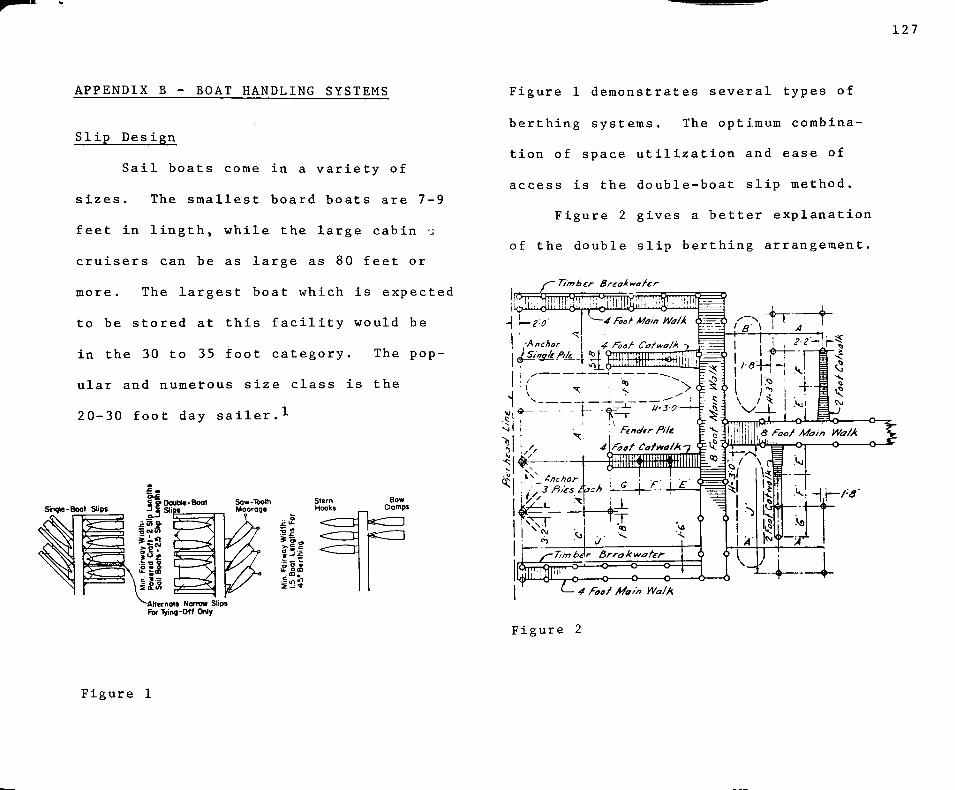
127
APPENDIX B - BOAT HANDLING SYSTEMS
Slip Design
Sail boats come in a variety of
sizes. The smallest board boats are 7-9
feet in lingth, while the large cabin -i
cruisers can be as large as 80 feet or
more. The largest boat which is expected
to be stored at this facility would be
in the 30 to 35 foot category. The pop
ular and numerous size class is the
20-30 foot day sailer,^
stern Hooks
Bow Clamps
'~Alternatg NamM Slips For-lying-Off Only
Figure 1 demonstrates several types of
berthing systems. The optimum combina
tion of space utilization and ease of
access is the double-boat slip method.
Figure 2 gives a better explanation
of the double slip berthing arrangement.
• Timber Breakwater
4 Foa^ Main Walk
F i g u r e 2
F i g u r e 1
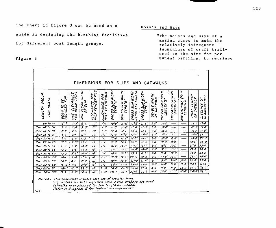
128
The chart in figure 3 can be used as a
guide in designing the berthing facilities
for dirrerent boat length groups.
Figure 3
Hoists and Ways
"The hoists and ways of a marina serve to make the relatively infrequent launchings of craft trail-ored to the site for permanent berthing, to retrieve
DIMENSIONS FOR SLIPS AND CATWALKS
LE
NG
TH
C
RO
UP
FOR
B
OA
TS
Up ro U Over W to / 6 ' 0\ier /e to /a' Over /a' to 20' Over 20 to 22 Over ZZ to 25'
BE
AM
T
O B
E
PR
OV
IDE
D
FO
R
MIN
. C
LEA
RA
NC
E
FO
R
BE
AM
-TO
TA
L
6 - 7 ; 2-3' 7-4' j Z:4' ao 8-7
9-3
/0-3 Over 25to 3^' ^ r-3' Over 30'to iS' Over 3S to 40 Over 40 to 45' Over45'to 50' Over SO'to &0' Over 60 to 70 Over TO'to 80'
12 3 13 3 /V - / ' 1411 16 6' /a-r 19 9
2'-5 2 6
2-6' Z-IO' 30
3-5" 3-3-3-/0 4-1
4-6
4-11-5-2-
MIN
. C
LEA
R
WID
TH
OF
SL
IP
S-IO' 9-e-10 s /i-r 11-9' i3'-r /4-y /5-0 16/1' l7'-i/' /9'0' 2/'0 230' 24-ir
ALL
OW
AN
CE
FO
R
HA
LF F
EN
DE
R P
ILE
lO"
10'
10-
10'
10'
10'
10
10'
10
10
10
lO'
10'
/o-
ALL
OW
AN
CE
F
OR
H
ALF
OF
CA
TWA
LK
I'-r /-/-I'-r i-r i-r I-r I-r I-r i-r i-r r-r r-r 2-/(7-2-IO~
GR
OS
S S
LIP
WID
TH
TYP
E "
A"
10-9' / / • • 7
72-4-73 0 13-8' J SO 76'-2-n-T le'/o' 79-/0' 20-ir 22-ir 26-a' ZB-7
GR
OS
S S
LIP
WID
TH
TY
PE
'B"
70-6-l/'-4-72-7' 7t'-9-/3-S' /4-9-/5-/r
n-4-18-7-/9-7' 20-8' 22 a 24 3' 26-7'
GR
OS
S S
LIP
WID
TH
US
ING
4 F
T F
LOA
TS
//-a' 12-e, 73-3' /3'-/r 74-7' 7SII /7-r j6-e 19-9' 20-9' 21-10' 23-/0' 25'-/0~ 27-9'
GR
OS
S S
LIP
WID
TH
TYP
E '
C'
11-2' 12-0 129' 13-5' 74-r /S-S' /6-7-IB-0~ 19-3 20-3-21-4-23-4 25-4 26,-3
US
AB
LE
WID
TH
OF
CA
TWA
LK
2-0' Z-0~ 20' 2 0-
2-0' Z-O-2-0~ 2-0-20'
2 0' 2-0-2-0' 4-0' 4-0'
IST
CA
TWA
LK S
PA
N
LEN
GTH
"E
"
720
720-740' 3 0~ 10-0' 70'-0-/O'O' /20' /2-0-/40' 9 0-ii-o-ll-O' / / -<?•
2ND
CA
TWA
LK S
PA
N
LEN
GTH
"F"
ao' 6-0
a-Q-70-0 70'-0~ /2-0' 7Z0-9-0' ii-o-//••O'
//'•o-
3RD
CA
TWA
LK S
PA
N
LE
NG
TH
'6'
^ •
lO'-O' /2'0 I2'0-7Z-0-
TOTA
L LE
NG
TH
OF
CA
TWA
LK
72 0 72-0' 74 0 76-0' /a-o'
78-0' ZOO
22-0 240
260-28-0' 34-0' 34-0' 34-0
DIS
TA
NC
E
'J'
TO A
NC
HO
R P
ILE
/7-0 /9-0' 2/0' Z30
ZS-0' 28 0
330
38-0' 43-0' 48 0' 53-0 G30
73'0' 83-0
NoTCS: This tabulation is based upon use of traveler irons. Slip nidths arc to he adjusted ntien 3 pile onctiors are used. Catwalks lo be planned for full length as needed. Pefer to Diaqram E for lupical arranycme^nls.

129
them for repairs instead of drydocking, and>lto augment the ramp-launching of the smaller trailered craft that are not permanently berthed in p ermanentiy the slips''^
There are two kinds of equipment that are
to be used in conjunction with this pro
ject. They are the Jib-Crane and the
Monorail System, These two have been
chosen because of their widespread use
and familiarity,
"The Jib-Crane has a relatively short, knee-braced horizontal arm extending out from a vertical post or stanchion that is strong enough to handle the entire load by cantilever action from its base,"^
This crane is somewhat limited in It's
capacity but will be able to handle any
craft which could conceivably be needed
in this facility. The arm of the Jib-
Crane is free to pivot 360° about its
base. For this reason tethering lines
are rpniiTT-o»1 t-' -i
base. For this reason tethering lines
are required to dilp the boat from
swinging out too far in a pendulum-like
motion. Access must be provided to the
Jlb-Crane. The boat and trailor will
be free to maneuver into position under
the crane without obstruction.
Figure 4
Figure 4 will serve to give the designer
some idea of the form and function in
conjunction with the boat service area.
The boat is removed from the water and

130
placed on a dolly similar to those
depicted in figure 5, It can then be
maneuvered about on land by using a
forklift or other small vehicle.
-A—n
/ STRAPS
^
/
LJ -^
PLAN OF DOLLY
£ SIDE VIEW
-ir" CASTERS > ^ ^
PLAN OF DOLLY
" ^
SIDE
y VIEW
kr
¥f\ / n T r — ^ •
END VIEW
For more detailed infromation on
boat handling equipment the designer is
encouraged ot examine the book "Boat
Handling Equipment in the Modern Marina"
published by the National Association of
Engine and Boat Manufactures, 1959.
Figure 5

131
Ramps and Parking
A minimum of two ramps should be
provide for patron use. These should be
located adjacent to the Jib-Crane and
Monrail System and should conform
to the dimensions and specifications
in figure 6.
-25% (4:1) Mo.. Slop*
)• ^ 1 Wo»«r Lin* —' 1
LAUNCHING RAMP PROFILE
Figure 6
Figures 7 through 10 give required
dimensions for two types of parking
arrangements and are included here for
the designers reference.
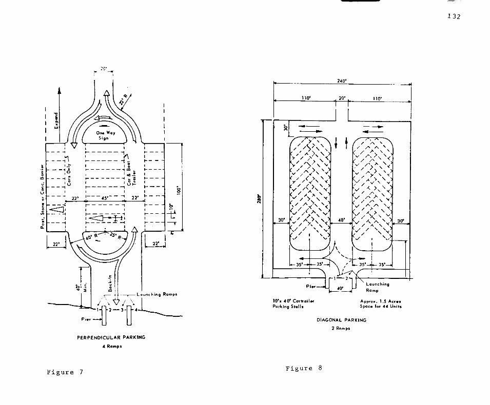
ro'
^
22*
/ - V / \ -LouncVi ing Romp*
240'
no* -t^ 110'
30'
• ' ' /< > ^ ")l
x '
1—35*
\ I /"v A \
^ A
/
•y
30"
35* ^ 3 5 ' -
Pi«
2 — 3 -
Pler
lO'x 4 0 ' CortroiUr Parking Stalls
^
35'—.
1 2
40* \ Lounch ing
Romp
Approx. 1.5 Acr«s Spoce (or 44 Uni ts
DIAGONAL PARKING
2 Ramps
P E R P E N D I C U L A R PARKING
4 Ramps
132
F i g u r e 7 F i g u r e 8

1 3 3
(4-Rad Right of Woy)
Approx. 0.60 Acres
10 Cor-troi lers
10 Cars ^lus
F i g u r e 9 F i g u r e 10

134
FOOTNOTES: APPENDIX B - BOAT HANDLING EQUIPMENT
1. Interview with Ken Abbott; Owner/Manager "Paddles 'n Sails" sailboat distributorship, Lubbock, Texas.
2. Report on Small Craft Harbors, (Task Committee on Small Craft Harbors), 1969, pg. 127
3. IBID, pg, 128

FIGURES: APPENDIX B - BOAT HANDLING EQUIPMENT
135
1- Report on Small Craft Harbors. (Task Committee on Small Craft Harbors, 1969) pg, 95.
2, Joseph De Chiarra, Time Saver Standards for Building Types, (Mc Graw-Hill, New York et,al,, 1973) pg, 1214,
3, IBID,, pg, 1214
4, Andrew R, Mack, Boat Handling Equipment in the Modern Marina, (The National Association of Engine and Boat Manufacturers, Inc,, New Yark 1959) pg,30,
5, IBID., pg.30
6, De Chiarra, op.cit., pg. 1216
7, IBID,, pg, 1216
8, IBID,, pg, 1216
9, IBID., pg. 1217
10, IBID., pg, 1217

136
BIBLIOGRAPHY: BOOKS AND PERIODICALS
^^'^Rese!rch^^i?74): ^^'^^" ^ ° " Living., (Ithaca, N,Y.; Center for Urban Development
Conoscenti, Thomas, "Economic Overview" Boating Industry. Vol. 44, No. 9, Sept.1981.
°^ ^Yor^dt ar^^l973)"'^ ^ '' '' Standards for Building Types. (Mc Graw-Hill, New
Fuller, John, Chief's Manual of Kitchen Management. (B.T. Batsford Ltd. London 1962).
Gahl, Jim, Fort Worth Boat Club, unpublished thesis
Gallico, Paul, Farewell to Sport. (Alfred A. Knopf, New York, London 1938).
Harris, Norman C , Modern Air Conditioning Practice. 2nd ed. (Mc Graw-Hill, New York et. al.) 1^74^ '
Kennedy, Robert, The House and the Art of It's Design. (Reinhold Publishing New New York, 1951)^ '
Kraus, Richard, Recreation and Leisure in Modern Society (Appleton-Contury-Crafts 1971). •
Leavy, Patrick, Recreational Geography, (Newton Abbott, London, Vancouver, 1971).
Mack, Andrew R. , Boat Handling Equipment in the Modern Marina. The National Association of Engine and Boat Manufacturers, Inc., New York, 1959.
Means, Robert S., Building Construction Cost Data, (Robert Snow Means Co., Kingston Mass., 1981).
Medlin, Marianne, A Townhouse Community for Lake Ray Hubbard. Dallas, unpublished Thesis.
Ramsey and Sleeper, Architectural Graphic Standards, (John Wiley and Sons, New York, 1970).

137
Rapoport, Rhona and Robert N., Leisure and the Family Life Cycle, Routledge and Kegan Paul, London 1975).
Ruffner, James A., The Weather Almanac, (Gale Research Book Co., Detroit).
St. Marie, Satenig S., Homes are for People, (John Wiley and Sons, New York 1973).
Untermann, Richard, Site Planning for Cluster Housing. Van Nostrand Reinhold, New York, 1977) .
Webster's New Collegiate Dictionary, G & C Merriam and Co., Springfield, Mass., 1977) .
Zadig, Earnest P., The Complete Book of Boating, Prentice-Hall Inc.. Englewood Cliffs , N.J. , 1976) ,
138
BIBLIOGRAPHY: GOVERNMENT DOCUMENTS
Outdoor Recreation for America, A report to the President and the Congress by the Outdoor Recreation Resources Commission, 1962,
Report on Small Craft Harbors. Task Committee on Small Craft Harbors, 1969,
Soil Survey of Tarrant County, Texas. U.S, Department of Agriculture Soil Conservation Service, 1981,
Texas Outdoor Recreation Plan, Texas, Parks and Wildlife Department Comprehensive Planning Branch, Austin, 1975,

139
BIBLIOGRAPHY; INTERVIEW.^
Ken Abbott, Owner/Manager "Paddles 'n Sails" Boat Distributorship, Lu
Mel Stuart, General Manager, Hillcrest Country Club, Lubbock, Texas,
bbock, Texas

E,M,Y,C,
JEFF FORREST
SPRING '82 THESIS

A WORD
Now that the whole ordeal is
over I would like to offer some ad
vice which the reader may or may not
choose to follow. First, and fore
most, have fun. Enjoy what you're
doing. If you don't play with your
design the whole project will get
old fast. Please yourself, if it
comes down to it, stand up to your
professors and back up your decisions
with facts. Lastly, explore every
option, especially the "stupid"
ones, A couple of those "stupid"
ideas became the major concepts in
the design of E,M,Y,C,
PROGRAM CONSIDERATIONS
Gathered from the original
program and flavored with the aspira
tions of the designer the major
Program Considerations to be attended
to in the design of E,M,Y,C, were:
1) Separation of incompatible act ivit ies
2) Involvement of total membership
3) Simultaneous use by many different groups
4) Strong visual statement from land and lake
5) Experience "Romantic" imagery of sailing
1) Separation of Incompatible Activiti ies
-Incompatible in the sense of noisy vs, quiet, passive vs, active, young vs, old. This was accomplished by dividing the programmed activities into two groups. Active and Passive. The Active Activities being the athletics oriented activities of Locker Rooms, Racquetball Courts, Bar and Grille, etc. The passive activities being those centering on dining. Dining Rooms, Cocktail Lounge, Kitchen, etc. Along with the managerial offices and Regatta Organization. The active grouping possessed a relaxed atmosphere,

one of cut-offs and sandals, etc., while the Passive Areas became more formal, with coat and tie becoming the atmosphere.
By separating the activities in this manner it was felt that club members could more easily enjoy whatever activity they were engaged in without the fear of being intruded upon by others engaged in an activity of totally different nature.
2) Involvement of Total Club Membership
-The thrust of this statement is to involve the whole family in activities each member would find enjoyable. Thereby reinforcing the connection between the club and its members. The separation of activities makes achievement of this goal much easier. Automatically, some of the potential interferences are eliminated due to the fact that most of the divisions according to type of activity correspond roughly to divisions in age groups. The older patrons tending to be more passive and younger more active. However, there are of course always exceptions and allowances for these exceptions were made.
By creating the street-like ' '-V:. .
board walk dividing both activity-groupings it is possible to provide all with an opportunity to get involved in the many activities of the club without participating, ie. spectating. This also allows the newly arrived member the opportunity to know at a glance who else is at the club and what Is going on.
3) Simultaneous Use By Many Different Groups
-Again, the separation of incompatible activities makes achieving this third goal easy. Since the types of activities are separated and segregated the allowance Is automatically made for the different interest and age groups to use club facilities at their leisure without interference from or in conjunction with other groups.
4) Strong Visual Statement From Land and Lake
-This is a bital element in the clubs quest for identity. The white stucco building material was chosen for its contrast with the green curtain of trees beyond, This contrast, in conjunction with the many variations in form visible from the lakeside are intended to make the E.M.Y.C. a highly visible landmark. One
that club members can be especially proud of.
5) Experience "Romantic" Imagery of Sailing
-This goal is largely a result of the designer's input. The imagery incorporated in the design of E.M.Y.C. consist of both audio and visual stimulil. Some examples of such are: The board walk and the sound made when one walks over it. The triangular shapes of the white stucco walls being similar to the sails of the boats, pole construction of the deck structure which reflects the verticality found in the masts of the boats. The decks and high vantage points where one can view the widow's walks in sea board construction.
DESIGN EVOLUTION
In order to arrive at the major
controlling concept many types of
ordering systems were explored.
Among those considered were vertical
stacking, horizontal or linearity.
and linear separation. The concept
chosen Is considered to be an
amalgamation of each of these with
some other points added.
The concept chosen is one in
which the separation of the Passive
and Active Activities takes place
along a linear axis, which connects the
parking lot and the dock areas.
This linear axis acts as a street
which all of the major activities
of the club feed off of, a sort of out
door corridor.
STRUCTURAL/MECHANICAL SYSTEMS
The structrual system chosen is
light wood framing with applied stucco
exterior and wood shingle roofing.
Wood framing was chosen for its economy
and because of its ability to coexist
so easily with the immediately adjacent
housing development to the west.
The Mechanical System is a
simple, forced air system with the
major fan and boiler equipment locat
ed below the main dining room and
the men's locker room. The ducts
and water pipes run through vertical
chases located roughly in the center
of each building. Then the ducts
branch off and run in the truss
spaces to the areas of the building
they serve.