e-field of a long wire
TRANSCRIPT

FdM
1
Electromagnetism
University of Twente
Department Applied Physics
First-year course on
Magnetism: topics
Version 2: Sept. 2017
© F.F.M. de Mul
www.demul.net/frits

FdM
2
Presentations: • Electromagnetism: History
• Electromagnetism: Electr. topics
• Electromagnetism: Magn. topics
• Electromagnetism: Waves topics
• Capacitor filling (complete)
• Capacitor filling (partial)
• Divergence Theorem
• E-field of a thin long charged wire
• E-field of a charged disk
• E-field of a dipole
• E-field of a line of dipoles
• E-field of a charged sphere
• E-field of a polarized object
• E-field: field energy
• Electromagnetism: integrations
• Electromagnetism: integration elements
• Electromotor and Dynamo
• Gauss’ Law for a cylindrical charge
• Gauss’ Law for a charged plane
• Laplace’s and Poisson’s Law
• B-field of a thin long wire carrying a
current
• B-field of a conducting charged
sphere
• B-field of a homogeneously
charged sphere
Download from: www.demul.net/frits; scroll to “Electromagnetism”

FdM
3
Electromagnetism Magnetism: topics
Contents:
1. Magnetic force on a current wire
2. Hall effect
3. Magnetic field of a line current
4. Idem. Circular circuit
5. Idem. Circular solenoid
6. Magnetic force between currents
7. Why is the wire moved by Lorentz force?
8. Ampère’s Law
9. B-field from a thick wire
10. Magnetic induction of a solenoid
11. Symmetries for Ampère’s Law
12. Magnetic pressure
13. Magnetic vector potential A
14. Magnetic dipole
15. Magnetization and Polarization
16. Magnetic circuit: torque and energy
17. Electret and Magnet
18. B- and H-fields at interface
19. Toroid with air gap
20. Induction: conductor moves in field
21. Induction: Faraday’s Law
22. Induction in rotating circuit frame
23. Electromagnetic brakes
24. Coupled circuits
25. Coax cable: self inductance
26. Magnetic field energy
27. Maxwell’s Fix of Ampère’s Law
Movie part I: 1-13 ; part II: 14-27

FdM
4
1. Magnetic Force on a Current Wire
eT dS
dl=dl.eT
| j | = dI/dS
j = n q v (n = # particles/m3)
Lorentz force on one charge: F = q v x B
….. per unit of volume : f = nq v x B = j x B
….. on volume dV : dF = j x B. dV
dF = j x B. dS.dl
j = j.eT dF = j.dS. eT x B . dl
dF = I . dl x B
Suppose: total current = I ;
cross section S variable
B
F = I.eT x B dl = F = I. L. eT x B
Straight conductor in homogeneous field:
B F pointing ┴ plane of drawing

FdM
5
2. Hall effect
G H
P
Q B
I I
d
l a
Suppose n charge carriers / m3
F
v
B-field causes deviation of path of charge carriers
Stationary case: Fmagn = Felec q v B = q EHall
Build up of electric field EHall between Q and P: Q+ ; P-
With j = nqv = I/(ad) nqad
IBvBEHall
nqa
IBdEVVV HallPQHall . :potential Hall VHall ~ B
magnetometer

FdM
6
I
3. Magnetic field of a line current
dlr
I2
0
4 :Savart &Biot rT ee
dB
P
R
Question: Determine B in P
O
dl=dz
dzr
IdB
2
0 sin
4
dzzR
R
zR
IdB
2222
0 1
4 : z var (1)
222
0
sinsin
sin
1
4 : var (2)
Rd
R
IdB
φ
0
2
:Result
eBR
IP
er
Approach: Current line elements dl
dl=dl.eT
z r
Integration over z from - to +
Integration over from 0 to , with z/R =-tan θ
Calculation: eT x er = e ;
tangential component only: dB dB
e
B ~ 1/R: cylinder symmetry

FdM
7
4. Magnetic field of a circular circuit
dlr
I2
0
4 :Savart &Biot rT ee
dB
yeB2/322
2
0
2
.
Rr
RI
p
P
Question: Determine B in P
P rP
y
I l
R
Approach: Current line elements dl r
er
dl
dl = dl. eT
2222
0 21
4 Rr
RR
Rr
IdB
pp
y
l
y dlr
IdB
cos
1
4 2
0
rP
r R
dB
P
dBy
Calculation: eT x er = 1 ;
symmetry: y- component only:
dB
dBy

FdM
8
5. Magnetic field of a circular solenoid Radius: R ; Current I
Length: L
Coils: N , or per meter: n
Approach: Solenoid = set of circular circuits ;
and for each circuit:
yeB2/322
2
0
2
.
Rr
RI
p
P
rp is distance
from circuit to P
Each circuit: strip dy; current dI = n.dy.I
Question: Determine B in P
y P
Result for L :
B = 0 n I ey
Result independent of R, L
P
L
p Rr
RdynI
0
2/322
2
0 2
)...(yeB
O y
yP
L a
dy
y
rp = yp - y
rp
rp R

FdM
9
1
2
I1
I2
r12
6. Magnetic forces between currents Question: determine F12
(force exerted by 1 on 2) :
eT1
eT2 er1
e 1
Relations:
TL
rTθθ0
edlBdldF
eeeeB
.;
;2
dlI
R
I
F12
22 .. dlI 21T221 BeF
B12 Calculation
121 eB
12
10
2 r
I
1221 FF : If 21 LL
)(2
2
12
210r121 eF L
r
II
r11T2 eee
If currents have same direction:
force attractive

FdM
10
7. Why is the wire moved by Lorentz force ? (since inside the wire only the conduction electrons move,
and not the metal ions)
+ + + + + + +
+ + + + + + +
+ + + + + + +
I I
electron
Conductor:
- fixed ion lattice,
- conduction electrons
Hall effect: concentration of electrons (-
charge) at one side of conductor - - - - - - - -
Lattice ions feel a force FE upwards + FE
B v
FL
-q
This force (= FL ) is electric !!
B
Magnetic field B
plane of drawing

FdM
11
8. Ampère’s Law (1)
I Long thin straight wire; current I
B
e
rr
Idl
r
I
ll
2
22
00 eedlB
Law sAmpere' : 0Il
dlB
r
Question: Determine the
“Circulation of B-field”
along circle l dlBl
eB 0
r
I
2:Savart&BiotWith

FdM
12
8. Ampère’s Law (2)
I
B
e
2.
2.. 0 r
r
IdrB
cc
dlB
Ampere : 0Il
dlB
r
l
Question: Determine the
“Circulation of B-field”
along circuit c dlB
c
Ic
0 :again and dlB
Consequences:
1. More currents through c add up ;
2. Currents outside c do not contribute ;
3. Position of current inside c
is not important.
r B
dl
=r. d
d

FdM
13
Rr
Rr
I
Cylinder: radius R
S
I dSj :current
9. B-field from a thick wire
Options for current:
I: at surface II: in volume
(suppose: homogeneous)
S
00 dSjdlB I
l
IrrB 02).(
2
2
02).(:)(R
rIrrBII
02).(:)( rrBI r
IrB
2)( 0
0)( rB
2
0
2
.)(
R
rIrB
Use Ampere-circuits
(radius r):
R
I
2
0
I
II
R r 0
B
I & II

FdM
14
10. Magnetic Induction of a Solenoid Radius: R ; Current: I
Length: L >> R
Coils: n per meter I
Result: inside: B = 0 n I ez
outside: B = 0
ez
er e Components: Bz Br B
G Br : Gauss-box G: total=0
top =bottom wall=0 Br=0
Br
c c B : Circuit c (radius r):
Ampere: B .2r=0 B =0
B
1 2 Bz : Circuit 2: B(a)=B(b)=0
Circuit 1: Ampere: Bz l=0 n I l
a
b
l
Bz

FdM
15
11. Symmetries for Ampere’s Law
S
00 dSjdlB I
l
Wire,
long
Plane,
extending
Solenoid,
long
Toroid,
along core line

FdM
16
Plane layer L with current density j
j
L
12.Magnetic Pressure
Magnetic pressure: P = ½0 j2 = ½Be
2 /0 .
Example: this situation is met at the wall of a (long) solenoid. Then
the pressure is outward, thus maximizing the cross section area.
Suppose we add an external
field Be , with Be = BL , so that the
total field behind the layer = 0
Be B-field of the layer (circuit l ):
2 BL l = 0 j l BL = ½0 j ez
l
z
BL BL
x y
Be
j
Lorentz force on : (FL=I.L.eT Be):
dFL= (j.db).dl ½0 j ez
dFL= ½0 j2.db.dl ey dl
db
Be
dFL
area=db.dl
Question: why does a solenoid try to
maximize its cross section (“fitting flux”) ?

FdM
17
13. Vector potential A VE :potential (scalar) Electric
AB : potential (vector) Magnetic
Only the spatial derivatives of V and A are defined !
The absolute values of V and A can be determined
by integration, but up to a constant (integration) term.
Therefore, only potential differences of V and A
between two points in space have a physical meaning !
One of these points may act as the “reference point”.
zyx
zye
Ve
Ve
x
VE
zyx
z
AAA
e
yx
zyx ee
B

FdM
18
''
v
dvr
j
4B 0
13. Vector potential A
r = f (x,y,z, x’,y’,z’ ) !!!
'
2
0 '4
v
dvr
μ rejB
duvuvddvu .)(.
0)',','(;),,( jj zyxfzyxf} '
'
v
dvr
j
4B 0
''
v
dvr
j
4A 0
Definition of A:
Question: determine A in P
from Biot-Savart for B
er
P (x,y,z) r dv’ Flow
tube
v’
x’,y’,z’ j
AB
'
0 '.1
4v
dvr
μj
'
0 '1
4v
dvr
μj
''
v
dvrr
jj
4B 0
Swap differentiation (=f (xyz))
and integration (=f (x’y’z’)) :
FdM
19
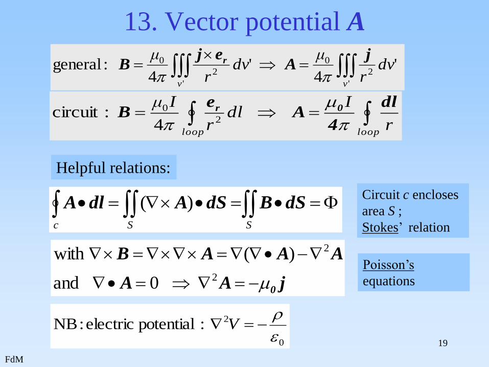
13. Vector potential A
Helpful relations:
SSc
dSBdSAdlA )(Circuit c encloses
area S ;
Stokes’ relation
jAA
AAAB
0
2
2
0and
)(with Poisson’s
equations
0
2 :potential electric :NB
V
looploop
r
Idl
r
Iμ dl
4A
eB 0r
2
0
4 :circuit
'
2
0
'
2
0 '4
'4
:generalvv
dvr
μdv
r
μ jA
ejB r
FdM 20
13. Vector potential A : examples (1)
looploop
v v
r
Idl
r
Iμ
dvr
dvr
μ
dl
4A
eB
j
4A
ejB
0r
0r
2
0
' '
2
0
4 :circuit
''4
:general
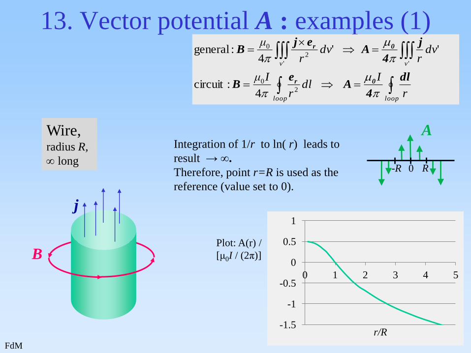
Wire, radius R,
long
B Plot: A(r) /
[μ0I / (2π)]
j
-1.5
-1
-0.5
0
0.5
1
0 1 2 3 4 5
r/R
Integration of 1/r to ln( r) leads to
result → ∞.
Therefore, point r=R is used as the
reference (value set to 0).
A
-R 0 R

FdM 21
13. Vector potential A : examples (2)
looploop
v v
r
Idl
r
Iμ
dvr
dvr
μ
dl
4A
eB
j
4A
ejB
0r
0r
2
0
' '
2
0
4 :circuit
''4
:general
x y
z
j
Babove
Bbelow
Aabove
Abelow
Sheet long and wide
Result: (c = const. [A/m])
j = c ex
B = ± ½ μ0 c ey
A = ½ μ0 c |z| ex
SSc
dSBdSAdlA )(
:Stokes :used
in a rectangle with sides // X- and
Z-axes
A-values with respect to
reference at z=0.

FdM
22
13. Vector potential A : examples (3)
looploop
v v
r
Idl
r
Iμ
dvr
dvr
μ
dl
4A
eB
j
4A
ejB
0r
0r
2
0
' '
2
0
4 :circuit
''4
:general
Solenoid, radius R,
long
B
j
A
A
~μ0 jR2/2r
r R
Toroid
B
j
A

FdM
23
13. Vector potential A : examples (4)
I B A
Circle circuit
looploop
v v
r
Idl
r
Iμ
dvr
dvr
μ
dl
4A
eB
j
4A
ejB
0r
0r
2
0
' '
2
0
4 :circuit
''4
:general
Example:
Single coil, R = 20 cm, I = 1 A
NB. Since A is a vector,
A does not form
equipotential planes, as
with electric V , with
planes ┴ E
Equi-”modulus” planes of
A have a donut-shape
with the coil as central
line.
A is directed tangentially
along the donut-surface.
)( VE

FdM
24
13. Vector potential A : examples (4) Example: Single coil, R = 20 cm, I = 1 A
10
20
50
100
Symmetry axis
Cross section in
XY-plane of
|A|-“donut”

FdM
25
13. Vector potential A
Applications of the vector potential: examples:
• time-dependent fields:
• electromagnetic waves
• dipolar radiation
• antenna design
• light (and other EM-waves) scattering and transport
• (e.g. refraction / reflection)
t
AVE

FdM
26
14. Magnetic Dipole (1): Far Field
rP
r
r’
O
erP
dl
P
I
Circuit with current I
AB Savart &Biot :'4
'
2
0
v
dvr
μ rejB
loop
v
r
I
dvr
circuit afor 1
and
general,in ''
dl4
A
j
4A
0
0
Goal: expression for A in P : A = f(rP)
in stead of A = f(r’)
for all r’-values in the circuit
Point P outside the circuit

FdM
27
14. Magnetic Dipole (1): Far Field
r
I dlA 0
4 :potentialVector
cos'.2'
11
22rrrrr
PP
rP
r
r’
O
erP
dl
P
I
Far field approx.: r’ << rP
PPP
PP
P
r
r
r
r
r
r
r
r
rr
r
' of powershigher .....cos
'1
1
cos'
2'
1
11
2
dldlAP .cos'.44
:Thus2
00
r
r
I
r
I
PP
Monopole-term
=0
Dipole-term
Goal: expression A = f (rP) in stead of
A = f (r’) for all r’-values in the circuit
(will be neglected)
cosine
rule

FdM
28
14. Magnetic Dipole (2): Dipole Moment
dlAP .cos'.4
2
0
r
r
I
PCalculate: A in P in YZ-plane
0
cos
sin
cos
sin
0
'cos'.
R
R
r rer
cossinR
0
.sin4
.cossin4
)cos)(.)(cossin(4
2
2
022
2
0
2
0
zy
PP
P
x
AA
Rr
IdR
r
I
dRRr
IA
Assume: circular circuit,
with radius R << rP
P
P’ y
x
z
r’
erP
rP
O
)cos.(. dRdlx
A
Symmetry: A will have an X-component only,
and thus dl as well.
x
y α
dl

FdM
29
14. Magnetic Dipole (3): Dipole Moment
dlAP .cos'.4
2
0
r
r
I
PCalculate: A in P in YZ-plane
0
.sin4
.cossin4
)cos)(.)(cossin(4
:screen previous
2
2
022
2
0
2
0
zy
PP
P
x
AA
Rr
IdR
r
I
dRRr
IA
r0 emA
24 Pr
Assume: circular circuit,
with radius R << rP
P
P’ y
x
z
r’
erP
rP
O
Define: dipole moment:
m = I. Area. en = IR2.en
en
A
A ┴ en and er ; A // ex

FdM
30
15. Magnetization and Polarization
L S en
Magnet = set of “elementary
circuits” ; n per m3
Total surface current = Itot
Total magnetic moment = Itot S en
Polarization Magnetization
Dipole moment: p [Cm] Dipole moment: m [Am2]
Polarization P = np [Cm-2]
= surface charge / m2
Magnetization M = nm [Am-1]
= surface current / m
Def.: Magnetization M = magnetic moment / volume =
surface current / length
V=SL
FdM
31
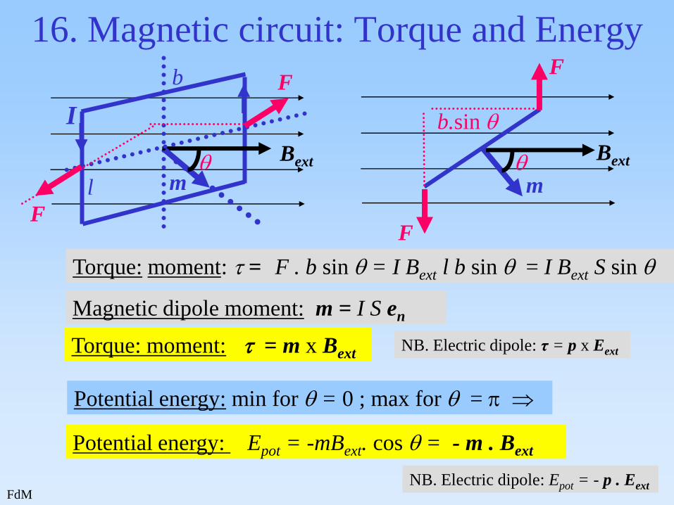
16. Magnetic circuit: Torque and Energy
Torque: moment: = F . b sin = I Bext l b sin = I Bext S sin
Magnetic dipole moment: m = I S en
Torque: moment: = m x Bext
Potential energy: min for = 0 ; max for =
Potential energy: Epot = -mBext. cos = - m . Bext
Bext
m
F
F F
F
m
Bext
b
l
b.sin
I
NB. Electric dipole: τ = p x Eext
NB. Electric dipole: Epot = - p . Eext
FdM
32
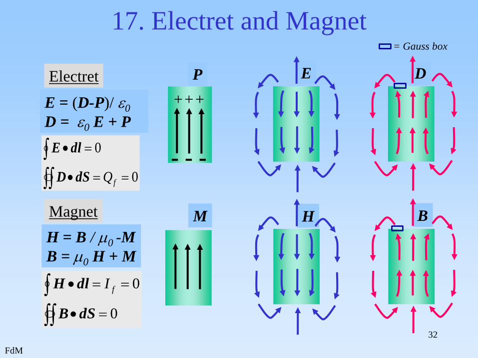
17. Electret and Magnet
E D
H B
Electret P
- - -
+++ E = (D-P)/0
D = 0 E + P
0
0
fQdSD
dlE
Magnet M
H = B / 0 -M
B = 0 H + M
0
0
dSB
dlH fI
= Gauss box

FdM
33
18. B- and H-fields at interface
L
A
H
B
L
A
H
B
22
2
11
1
tan
1
tan
1
2
1
2
1
tan
tan
r
r
Given: B1 ; 1 ; 2
Question: Calculate B2 B1
B2
1
2
1
2
Gauss box : B1.Acos 1 - B2.Acos 2 =0 B1 = B2
Circuit: : no I : H1.Lsin 1 - H2.Lsin 2 =0 H1// = H2//
Needed: “Interface-crossing relations”:
Relation H and B: B = 0 r H
0 and dABdlH freeI
2
1
2
1
tan
tan
r
rNB. For dielectric materials:

FdM
34
Suppose:
- toroid solenoid: R, L, N, r ;
- air gap, r =1 , width d <<R;
g = gap ; m = metal
I Core
line;
radius R
length L
19. Toroid with air gap
Question: Determine Hg in gap
Relations:
0
0
dAB
HBdlH rfI
Hg d + Hm (L-d) = N I
Bg =Bm
Bg=oHg ; Bm =0r Hm
Result:
r
g
m
r
rg
HH
dL
NIH
and
)1(
d
NB. In gap: Hg ~ µr N.
This is the technical magnetic
analogon of the homogeneous
electric field in an ideal capacitor
FdM
35
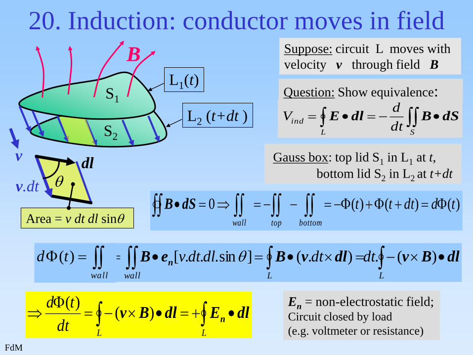
20. Induction: conductor moves in field
B
v
L1(t)
L2 (t+dt )
Suppose: circuit L moves with
velocity v through field B
Question: Show equivalence:
SL
inddt
dV dSBdlE
)()()(0 tddtttbottomtopwall
dSB
LLwall
dtdtdldtv dlBvdlvBeB n )(.).(]sin...[
LL
dt
tddlEdlBv n)(
)( En = non-electrostatic field; Circuit closed by load
(e.g. voltmeter or resistance)
Gauss box: top lid S1 in L1 at t,
bottom lid S2 in L2 at t+dt
S1
S2
wall
td )(
v.dt
dl
Area = v dt dl sin

FdM
36
21. Induction: Faraday’s Law
V0
B
c S I0
Static: 0 c
dlE
Vind
Dynamic:
B
c S Iind
Suppose changes
Vind 0
Non-electrostatic field EN
Sc
inddt
d
dt
dV dSBdlEN
Consequence: Let circuit c shrink, while keeping S constant.
S c c
S 00
Sc
dSBdlEN
For closed surface :

FdM
37
22. Induction in rotating circuit frame
Induction potential difference :
(II) Using flux change:
tlvBtlbB
lbdt
dB
dt
d
dt
dV
extext
extind
sin2sin
]cos[
dSBext
Bext
en
Bext
b
l
v
v
v
en
= t ; v= ½b
(I) Using Lorentz force:
tlvBlvB
V
extext
extind
sin2sin2
)(
dlBvdlEN
=EN

FdM
38
23. Electromagnetic brakes Why is a conducting wire decelerated by a magnetic field?
Case I: switch open
P
Q
v B Electrons feel FL FL
P
Q
v B Case II: switch closed
Potential difference VPQ : P - ,
Q + (= Hall effect)
FL
vL
FL moves electrons: vL ,
which will act on positive
metal ions: Fions.
Fions
FE
FL counteracted by FE
I FL2
which causes I and FL2 ,
which causes electric field,
brake on deceleration
until FL = FE

FdM
39
24. Coupled circuits (1): M and L
1
2 I1
Suppose: circuit 1 with current I1
Part of flux from 1 will pass
through 2 : 21
21 ~ I1
Definition: 21 = M21.I1
M : coefficient of mutual induction : “Mutual Inductance” :
[ H ] = [ NA-1m-1.m2.A-1] = [ NmA-2 ]
Suppose: Circuit 2 has current as well: I2
I2
Flux through 2: 2= 21 + 22 = M21 I1 + M22 I2
L : coefficient of self-induction “ (Self) Inductance”: M22 = L2
M and L are geometrical functions (shape, orientation, distance etc.)

FdM
40
24. Coupled circuits (2): toroid
Question: determine induction
coefficient of 1 in 2:
mutual induction M21
Flux from 1 through S : S = BS = 0 r N1 I1 S / L
Cross
section S
N1 , I1 N2
Core line: L
r
Linked flux from 1 through 2: 21 = N2 S = 0 r N1 N2 I1 S / L
Coefficient of mutual induction: M21 = 0 r N1 N2 S / L
This expression is symmetrical in 1 and 2: M21 = M12
This result is generally valid: Mij = Mji
FdM
41
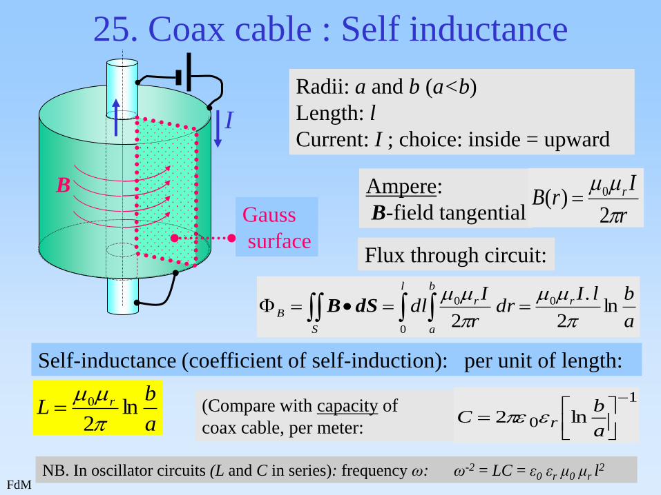
Radii: a and b (a<b)
Length: l
Current: I ; choice: inside = upward I
25. Coax cable : Self inductance
Ampere:
B-field tangential r
IrB r
2)( 0
Flux through circuit:
a
blIdr
r
Idl r
l b
a
r
S
B ln2
.
2
0
0
0
dSB
Self-inductance (coefficient of self-induction): per unit of length:
a
bL r ln
2
0
(Compare with capacity of
coax cable, per meter:
1
0 ln2
a
bC r
Gauss
surface
B
NB. In oscillator circuits (L and C in series): frequency ω: ω-2 = LC = ε0 εr μ0 μr l2

FdM
42
26. Magnetic Field Energy
x
z
y
Assume: currents may be everywhere in space.
I
H
H (B)-field: closed curves ┴ circuit.
Space = volume of “tiny” Gauss
boxes, with normal // H (or B).
dlHdSB IS
;
Magnetic power: dEm /dt = = Vind I = (dΦ/dt). I = L (dI/dt). I
dldSHBdlHdSB . 21
21
m
VcS
E
Compare: electric energy: dvv
ED21
EE
dvV
HB21
Example: 1 circuit c in XY-plane
dS dl
Magn. Energy: Em = ½ L.I2 = ½ Φ I

FdM
43
27. Maxwell’s Fix of Ampere’s Law
:Induction Sc
dt
ddSBdlEn Changing B-field causes an E-field
Question: Does a changing E-field cause a B-field ?
j
Suppose: chargeing a capacitor using j L
S1
L S1
0 dSjdlB L encloses S1 :
S2
L S2
0 dSjdlB L encloses S2 :
SSL
dt
ddSDdSjdlB :generalIn
L encloses S3 :
3
0
SLdt
ddSDdlB
S3
Volume enclosed
by S2 and S3:
32 S
f
Sdt
d
dt
dQdSDdSj
D

FdM
44
27. Maxwell’s Fix of Ampere’s Law
:Induction Sc
dt
ddSBdlEn
A changing B-field causes
an E-field around itself
SSL
dt
ddSDdSjdlB :Maxwell
A changing E-field causes
a B-field around itself
This is the starting point for self-propagating
ELECTROMAGNETIC WAVES
(see presentation about Waves)