dynax-maxxum 7 en
DESCRIPTION
Minolta Maxxum Dynax AlphaTRANSCRIPT
Minolta Co., Ltd. 3-13, 2-Chome, Azuchi-Machi, Chuo-Ku, Osaka 541-8556, Japan
Minolta Europe GmbH Minoltaring 11, D-30855 Langenhagen, GermanyReparatur/Repair Senator-Helmken-Strasse 1, D-28197 Bremen, Germany
Minolta France S.A. 365 Route de Saint-Germain, F-78420 Carrieres-Sur-Seine, FranceMinolta (UK) Limited 7 Tanners Drive, Blakelands, Milton Keynes, MK14 5BU, EnglandMinolta Austria Ges. m.b.H. Amalienstrasse 59-61, A-1131 Wien, AustriaMinolta Camera Benelux B.V. Zonnebaan 39, P.O. Box 6000, NL-3600 HA Maarssen, The Netherlands
Belgium Branch Prins Boudewijnlaan 1, B-2550 Kontich, BelgiumMinolta (Schweiz) AG Riedstrasse 6, CH-8953 Dietikon, SwitzerlandMinolta Svenska AB Albygatan 114, S-171 54 Solna, Sweden
Finland Branch Niittykatu 6 PL 37, SF-02201 Espoo, FinlandMinolta Portugal Limitada Av. do Brasil 33-A, P-1700 Lisboa, PortugalMinolta Corporation
Head Office 101 Williams Drive, Ramsey, New Jersey 07446, U.S.A.Los Angeles Branch 11150 Hope Street Cypress, CA 90630, U.S.A.
Minolta Canada Inc.Head Office 369 Britannia Road East, Mississauga, Ontario L4Z 2H5, CanadaVancouver Branch 230-3771 Jacombs Road, Richmond, B.C. V6V 2L9, Canada
Minolta Hong Kong Limited Room 208, 2/F, Eastern Center, 1065 King’s Road, Quarry Bay, Hong KongMinolta Singapore (Pte) Ltd. 10, Teban Gardens Crescent, Singapore 608923Shanghai Minolta Optical Products Co., Ltd. 368 Minolta Road, Songjiang, Shanghai, China
© 2000 Minolta Co., Ltd. under the BerneConvention and universal Copyright Convention
Printed in Malaysia 9222-2162-21 MM-C009E INSTRUCTION MANUAL
BA
SIC
OP
ER
ATIO
ND
ETA
ILE
D O
PE
RAT
ION
AP
PE
ND
IX

1
32
Thank you for purchasing a Minolta camera.A valuable tool for photographers, the Maxxum/Dynax 7 has beendesigned with precision in mind to help you capture your photo-graphic vision. As you use the Maxxum/Dynax 7, you will find thatits performance and reliability compliment your own photographicexpertise and raise your skills to a higher level.
The Maxxum/Dynax 7 features a newly developed 9-point AF sys-tem with center dual cross-hair sensors to give great flexibility whencomposing photographs, and the ability to switch between AF andMF, using the AF/MF control button, without changing holding posi-tions.
This is the first camera ever to incorporate a Navigation displaywhich gives easy to understand information on camera operationand Custom functions, available in 5 languages. Combined with theconventional lever and dial controls, the Navigation display providesflexible and clear operation.
This manual has been designed to help you understand the opera-tion of your camera and its functions. Please familiarize yourselfwith the names of the controls and their locations on the camera,then read the Basic Operation section. Once you’ve mastered basicoperation, move on to the Detailed Operation section to expandyour expertise.
This camera is designed to work specifically with lenses and acces-sories manufactured and distributed by Minolta. Using incompatibleaccessories with this camera may result in unsatisfactory perfor-mance or damage the camera and accessories.
FOR PROPER AND SAFE USE
Read and understand all warnings and cautions before using this product.
WARNINGBatteries may become hot or explode due to improper use.• Use only the batteries specified in this instruction manual.• Do not install the batteries with the polarity (+/–) reversed.• Do not subject batteries to fire or high temperatures.• Do not attempt to recharge, short, or disassemble.• Do not mix batteries of different types, brands, or ages.• Tape over lithium battery contacts to avoid short-circuit when dispos-
ing of batteries, and follow local regulations for battery disposal.
Keep batteries and other things that could be swallowed away fromyoung children. Contact a doctor immediately if an object is swallowed.
Immediately remove the batteries and discontinue use if…• the camera is dropped or subjected to an impact in which the interior
is exposed.• the camera emits a strange smell, heat, or smoke.
Do not disassemble. Electric shock may occur if a high voltage circuitinside the camera is touched. Take your camera to a Minolta ServiceFacility when repairs are required.
Do not look directly at the sun through the viewfinder.
CAUTION
Do not allow a camera lens to point directly at the sun. Fire may occur ifsunlight comes to focus on a flammable surface. Replace the lens capwhen the product is not being used.
54
TABLE OF CONTENTS
Table of Contents ..............................................................................4Name of Parts ...................................................................................8Quick Operation ..............................................................................14
BASIC OPERATIONBatteries ..........................................................................................17Loading Film....................................................................................20Handling the Camera ......................................................................23Taking Pictures in Full-Auto ............................................................24Focusing..........................................................................................28Using the Built-in Flash ...................................................................31Rewinding the Film..........................................................................33
DETAILED OPERATIONNavigation Display ..........................................................................36
Display Selection .................................................................37When Upper Part Turns Black .............................................43Display Brightness/Contrast ................................................44
FocusingFocus Mode .........................................................................46AF/MF Control Button ..........................................................50Focus Area...........................................................................53AF Illuminator.......................................................................59
ExposureP Mode.................................................................................61A Mode.................................................................................63S Mode ................................................................................66M Mode................................................................................69
MeteringSelectable Metering .............................................................74Exposure Compensation .....................................................77Automatic Exposure Lock (AEL)..........................................81Setting the ISO Manually .....................................................86
DriveContinuous ..........................................................................88Self-Timer.............................................................................90Exposure Bracketing............................................................92Multiple Exposure ...............................................................96
FlashFlash Mode Switch ..............................................................99Red-eye Reduction ............................................................100Rear flash Sync .................................................................101Slow-shutter Sync..............................................................102Flash Compensation..........................................................103Flash Bracketing ................................................................104Accessory Flash ................................................................107Flash Metering ...................................................................108High Speed Sync ...............................................................110Wireless/Remote Off-camera Flash ...................................112PC Terminal........................................................................118
Additional FeaturesDate/Time Imprinting..........................................................120Eye-Start ............................................................................125Time Exposures (Bulb) ......................................................126Depth-of Field Preview ......................................................128Diopter Adjustment ............................................................130Setting/Cancelling the Audio..............................................131
76
TABLE OF CONTENTS
Memory Storing memory .................................................................135Recalling settings in memory.............................................137
Data memoryStoring the data .................................................................141Film area and data number ...............................................143Data recall..........................................................................146Deleting stored data...........................................................151
Custom Functions1 AF priority/Shutter-release priority2 Film rewind start3 Film tip4 DX memory5 Release lock (film)6 Lens focus-hold button7 Eyepiece sensor activation8 Frame counter9 AF/MF control button10 AE-lock button11 Exposure bracketing/Flash bracketing sequence 12 Film rewind speed13 Meter display duration14 AF area display15 Front and rear control dial Lock16 Release lock (lens)17 AF drive speed
18 Exposure compensation control with rear control dialin P, A, and S mode
19 Control dial - exchanged control20 Flash-metering21 AF illuminator22 Tasking on the focus-mode switch - AF-A position23 AF using shutter-release button24 Full-auto mode of the exposure-mode dial25 Tasking on exposure mode dial - position “3”26 Flash burst with exposure compensation27 Detailed display 28 Operation display29 Large icon display30 Meter index display31 Exposure-history display32 Vertical display33 Imprint intensity34 Camera’s ID number 35 Language on navigation display
APPENDIXAccessory information .......................................................189Trouble shooting ................................................................192Care and Storage ..............................................................196Specifications.....................................................................198Index ..................................................................................202
98
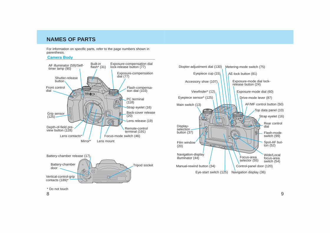
Camera Body
AF illuminator (59)/Self-timer lamp (90)
Battery-chamber release (17)
Vertical-control-gripcontacts (189)*
Battery-chamberdoor
Tripod socket
* Do not touch
NAMES OF PARTS
Accessory shoe (107)
Eyepiece cup (15)
Drive-mode lever (87)
Exposure-mode dial lock-release button (24)
Viewfinder* (12)
Eyepiece sensor* (125)
AE-lock button (81)
Top data panel (10)
Navigation display (36)
Metering-mode switch (75)
Display-selection button (37)
Navigation-displayilluminator (44)
Diopter-adjustment dial (130)
Control-panel door (120)Manual-rewind button (34)
Eye-start switch (125)
AF/MF control button (50)Main switch (13)
Strap eyelet (16)
Film window(20)
Focus-areaselector (55)
Flash-modeswitch (99)
Exposure-mode dial (60)
Rear controldial
Spot-AF but-ton (52)
Wide/Localfocus-areaswitch (54)
Focus-mode switch (46)
Lens release (19)
Strap eyelet (16)
Built-inflash* (31)
PC terminal(118)
Lens mount
Back-cover release(20)
Shutter-releasebutton
Exposure-compensation diallock-release button (77)
Grip sensor(125)
Exposure-compensationdial (77)
Flash-compensa-tion dial (103)
Front controldial
Lens contacts*
Mirror*
Remote-controlterminal (191)
Depth-of-field pre-view button (128)
For information on specific parts, refer to the page numbers shown inparenthesis.
1110
NAMES OF PARTS
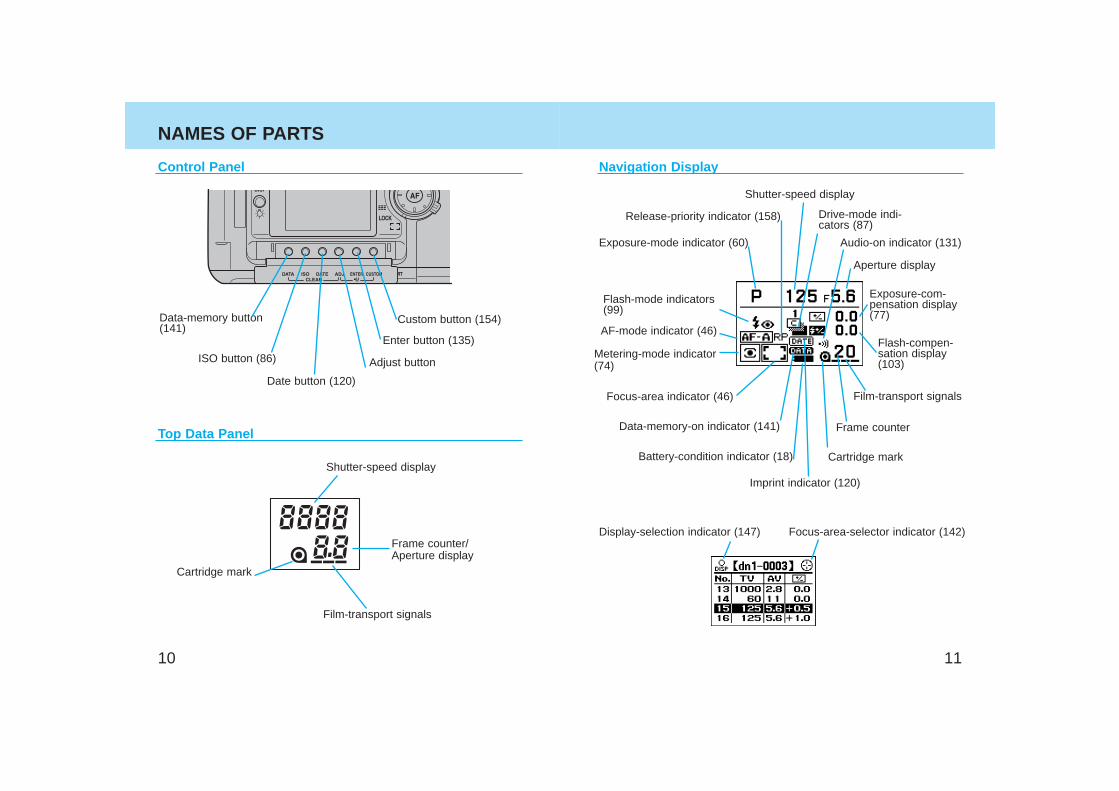
Control Panel
Top Data Panel
Cartridge mark
Film-transport signals
Frame counter/Aperture display
Adjust button
Enter button (135)
Custom button (154)
Date button (120)
ISO button (86)
Data-memory button(141)
Shutter-speed display
Navigation Display
Release-priority indicator (158)
Exposure-mode indicator (60)
Flash-mode indicators(99)
AF-mode indicator (46)
Metering-mode indicator(74)
Focus-area indicator (46)
Data-memory-on indicator (141)
Battery-condition indicator (18)
Imprint indicator (120)
Display-selection indicator (147) Focus-area-selector indicator (142)
Shutter-speed display
Aperture display
Exposure-com-pensation display(77)
Drive-mode indi-cators (87)
Flash-compen-sation display(103)
Frame counter
Film-transport signals
Cartridge mark
Audio-on indicator (131)
1312
NAMES OF PARTS
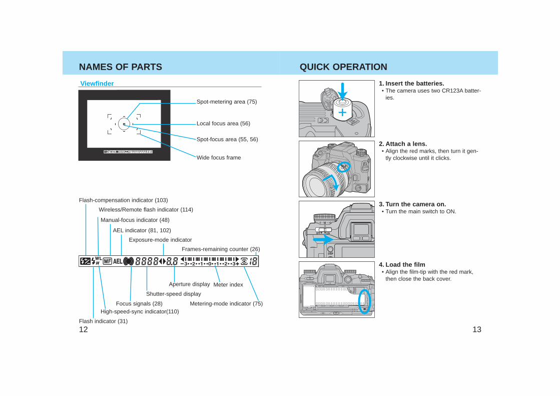
Viewfinder
AEL indicator (81, 102)
Focus signals (28)
Flash-compensation indicator (103)
Spot-metering area (75)
Spot-focus area (55, 56)
Flash indicator (31)
High-speed-sync indicator(110)
Wireless/Remote flash indicator (114)
Shutter-speed display
Exposure-mode indicator
Aperture display Meter index
Metering-mode indicator (75)
Frames-remaining counter (26)
Manual-focus indicator (48)
Wide focus frame
Local focus area (56)
QUICK OPERATION
1. Insert the batteries.• The camera uses two CR123A batter-
ies.
2. Attach a lens.• Align the red marks, then turn it gen-
tly clockwise until it clicks.
3. Turn the camera on.• Turn the main switch to ON.
4. Load the film• Align the film-tip with the red mark,
then close the back cover.
1514
QUICK OPERATION
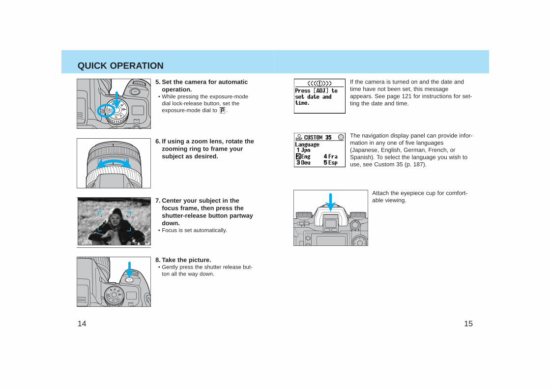
5. Set the camera for automaticoperation.
• While pressing the exposure-modedial lock-release button, set the exposure-mode dial to .
6. If using a zoom lens, rotate thezooming ring to frame yoursubject as desired.
7. Center your subject in thefocus frame, then press theshutter-release button partwaydown.
• Focus is set automatically.
8. Take the picture.• Gently press the shutter release but-
ton all the way down.
If the camera is turned on and the date andtime have not been set, this messageappears. See page 121 for instructions for set-ting the date and time.
The navigation display panel can provide infor-mation in any one of five languages(Japanese, English, German, French, orSpanish). To select the language you wish touse, see Custom 35 (p. 187).
Attach the eyepiece cup for comfort-able viewing.
1716
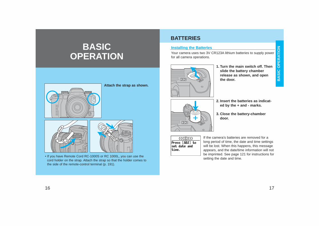
Attach the strap as shown.
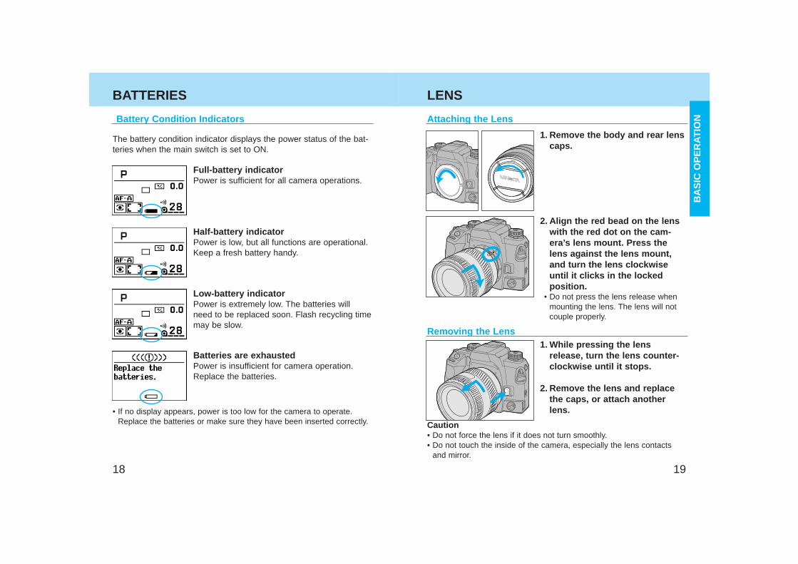
Your camera uses two 3V CR123A lithium batteries to supply powerfor all camera operations.
1. Turn the main switch off. Thenslide the battery chamberrelease as shown, and openthe door.
2. Insert the batteries as indicat-ed by the + and - marks.
3. Close the battery-chamberdoor.
Installing the Batteries
If the camera’s batteries are removed for along period of time, the date and time settingswill be lost. When this happens, this messageappears, and the date/time information will notbe imprinted. See page 121 for instructions forsetting the date and time.
BATTERIES
BA
SIC
OP
ER
ATIO
NBASIC OPERATION
• If you have Remote Cord RC-1000S or RC 1000L, you can use thecord holder on the strap. Attach the strap so that the holder comes tothe side of the remote-control terminal (p. 191).
1918
BATTERIES
Battery Condition Indicators
The battery condition indicator displays the power status of the bat-teries when the main switch is set to ON.
Full-battery indicatorPower is sufficient for all camera operations.
Half-battery indicatorPower is low, but all functions are operational.Keep a fresh battery handy.
Low-battery indicatorPower is extremely low. The batteries willneed to be replaced soon. Flash recycling timemay be slow.
Batteries are exhaustedPower is insufficient for camera operation.Replace the batteries.
• If no display appears, power is too low for the camera to operate.Replace the batteries or make sure they have been inserted correctly.
LENS
Attaching the Lens
1. Remove the body and rear lenscaps.
2. Align the red bead on the lenswith the red dot on the cam-era’s lens mount. Press thelens against the lens mount,and turn the lens clockwiseuntil it clicks in the lockedposition.
• Do not press the lens release whenmounting the lens. The lens will notcouple properly.
1. While pressing the lensrelease, turn the lens counter-clockwise until it stops.
2. Remove the lens and replacethe caps, or attach anotherlens.
Removing the Lens
Caution• Do not force the lens if it does not turn smoothly.• Do not touch the inside of the camera, especially the lens contacts
and mirror.
BA
SIC
OP
ER
ATIO
N
2120
LOADING FILM
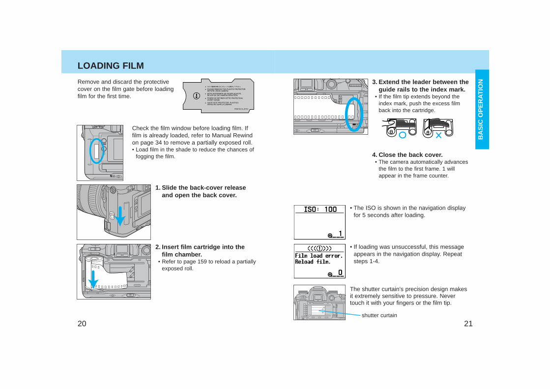
Check the film window before loading film. Iffilm is already loaded, refer to Manual Rewindon page 34 to remove a partially exposed roll.• Load film in the shade to reduce the chances of
fogging the film.
Remove and discard the protectivecover on the film gate before loadingfilm for the first time.
1. Slide the back-cover releaseand open the back cover.
2. Insert film cartridge into thefilm chamber.
• Refer to page 159 to reload a partiallyexposed roll.
3. Extend the leader between theguide rails to the index mark.
• If the film tip extends beyond theindex mark, push the excess filmback into the cartridge.
4. Close the back cover.• The camera automatically advances
the film to the first frame. 1 willappear in the frame counter.
• The ISO is shown in the navigation displayfor 5 seconds after loading.
• If loading was unsuccessful, this messageappears in the navigation display. Repeatsteps 1-4.
shutter curtain
The shutter curtain’s precision design makesit extremely sensitive to pressure. Nevertouch it with your fingers or the film tip.
BA
SIC
OP
ER
ATIO
N
2322
LOADING FILM
• Once the film is loaded, the back cover will lock until film rewind-ing is complete, preventing accidental opening.
• ISO is set automatically if DX-coded film is loaded. See page 86for changing ISO manually.
• Non-DX-coded film is automatically rewound at the end of the rollor after 36 exposures.
• Non-DX-coded film is set to the ISO from the previous roll. Referto page 86 to set the film speed manually.
• Do not use Polaroid Instant 35mm film. Winding problems mayoccur.
• Do not use infrared film in this camera. The camera’s framecounter sensor will fog infrared film.
HANDLING THE CAMERA
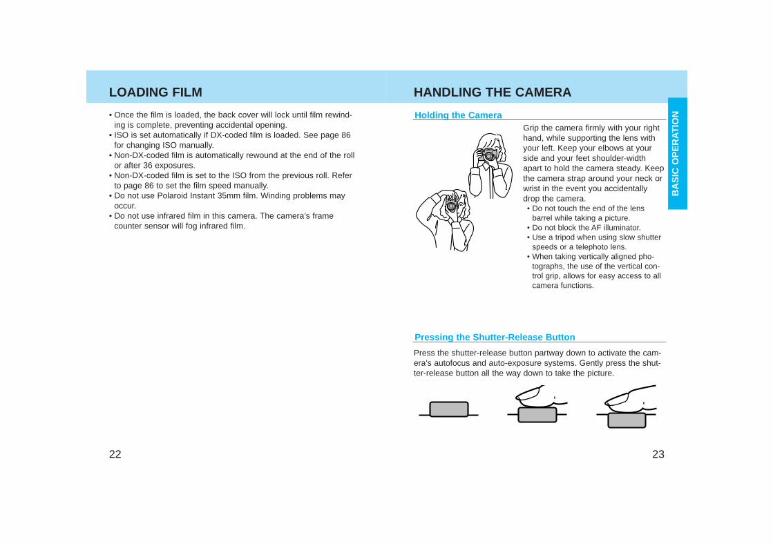
Holding the CameraGrip the camera firmly with your righthand, while supporting the lens withyour left. Keep your elbows at yourside and your feet shoulder-widthapart to hold the camera steady. Keepthe camera strap around your neck orwrist in the event you accidentallydrop the camera.• Do not touch the end of the lens
barrel while taking a picture.• Do not block the AF illuminator.• Use a tripod when using slow shutter
speeds or a telephoto lens.• When taking vertically aligned pho-
tographs, the use of the vertical con-trol grip, allows for easy access to allcamera functions.
Pressing the Shutter-Release Button
Press the shutter-release button partway down to activate the cam-era’s autofocus and auto-exposure systems. Gently press the shut-ter-release button all the way down to take the picture.
BA
SIC
OP
ER
ATIO
N
2524
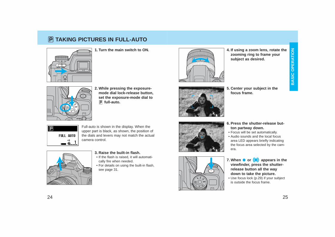
TAKING PICTURES IN FULL-AUTO
1. Turn the main switch to ON.
3. Raise the built-in flash.• If the flash is raised, it will automati-
cally fire when needed.• For details on using the built-in flash,
see page 31.
2. While pressing the exposure-mode dial lock-release button,set the exposure-mode dial to
full-auto.
Full-auto is shown in the display. When theupper part is black, as shown, the position ofthe dials and levers may not match the actualcamera control.
4. If using a zoom lens, rotate thezooming ring to frame yoursubject as desired.
6. Press the shutter-release but-ton partway down.
• Focus will be set automatically.• Audio sounds and the local focus
area LED appears briefly indicatingthe focus area selected by the cam-era.
7. When or appears in theviewfinder, press the shutter-release button all the waydown to take the picture.
• Use focus lock (p.29) if your subjectis outside the focus frame.
5. Center your subject in thefocus frame.
BA
SIC
OP
ER
ATIO
N
2726
TAKING PICTURES IN FULL-AUTO
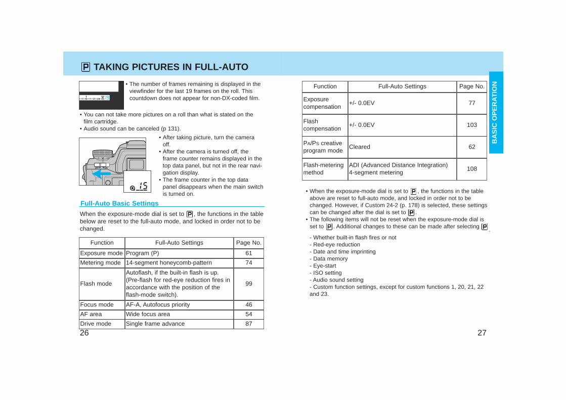
Full-Auto Basic Settings
When the exposure-mode dial is set to , the functions in the tablebelow are reset to the full-auto mode, and locked in order not to bechanged.
Function
Exposure mode
Metering mode
Flash mode
Focus mode
AF area
Full-Auto Settings
Program (P)
14-segment honeycomb-pattern
Autoflash, if the built-in flash is up.(Pre-flash for red-eye reduction fires inaccordance with the position of theflash-mode switch).
AF-A, Autofocus priority
Wide focus area
Page No.
61
74
99
46
54
Function
Exposure compensation
Flash-meteringmethod
Full-Auto Settings
+/- 0.0EV
ADI (Advanced Distance Integration) 4-segment metering
Page No.
77
Flash compensation
+/- 0.0EV 103
PA/PS creativeprogram mode
Cleared 62
108
• When the exposure-mode dial is set to , the functions in the tableabove are reset to full-auto mode, and locked in order not to bechanged. However, if Custom 24-2 (p. 178) is selected, these settingscan be changed after the dial is set to .
• The following items will not be reset when the exposure-mode dial isset to . Additional changes to these can be made after selecting
.- Whether built-in flash fires or not- Red-eye reduction- Date and time imprinting- Data memory- Eye-start- ISO setting- Audio sound setting- Custom function settings, except for custom functions 1, 20, 21, 22and 23.
• The number of frames remaining is displayed in theviewfinder for the last 19 frames on the roll. Thiscountdown does not appear for non-DX-coded film.
• After taking picture, turn the cameraoff.
• After the camera is turned off, theframe counter remains displayed in thetop data panel, but not in the rear navi-gation display.
• The frame counter in the top datapanel disappears when the main switchis turned on.
• You can not take more pictures on a roll than what is stated on thefilm cartridge.
• Audio sound can be canceled (p 131).
Drive mode Single frame advance 87
BA
SIC
OP
ER
ATIO
N
2928
FOCUSING
Focus SignalsThe following signals appear in theviewfinder to indicate the focus statuswhen the shutter-release button ispressed partway down.
Focus is confirmed.
Continuous autofocus – Focus is confirmed.
Continuous autofocus – Lens focusing. Shutter islocked.
(Blinks) Focus cannot be confirmed – Shutter islocked.Subject is too close or is one of the special focus situa-tions described on page 30.
• In the above chart, the shutter is locked when the lens is focusing orwhen focus cannot be confirmed. To change so that the shutter canbe released, even if focus has not been confirmed, select Custom1-2.
• If eye-start is on, it is possible to activate focus by bringing the cam-era to your eye. See eye-start for more information (p. 125).
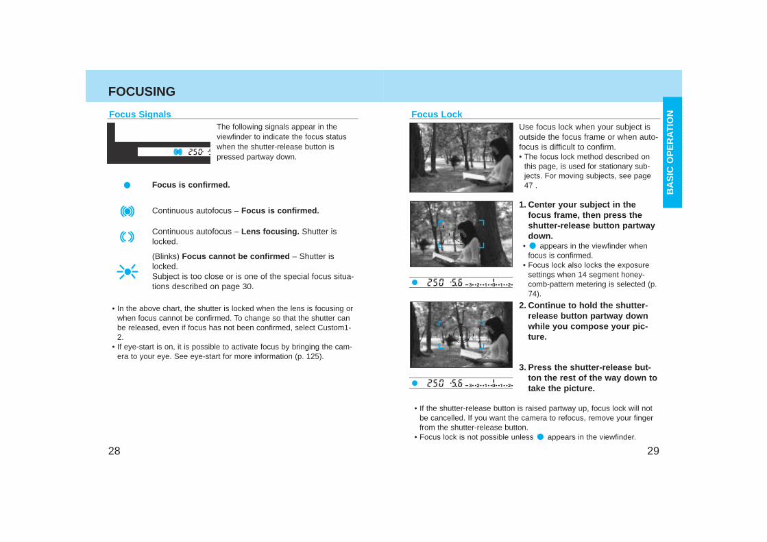
Focus LockUse focus lock when your subject isoutside the focus frame or when auto-focus is difficult to confirm.• The focus lock method described on
this page, is used for stationary sub-jects. For moving subjects, see page47 .
1. Center your subject in thefocus frame, then press theshutter-release button partwaydown.
• appears in the viewfinder whenfocus is confirmed.
• Focus lock also locks the exposuresettings when 14 segment honey-comb-pattern metering is selected (p.74).
2. Continue to hold the shutter-release button partway downwhile you compose your pic-ture.
3. Press the shutter-release but-ton the rest of the way down totake the picture.
• If the shutter-release button is raised partway up, focus lock will notbe cancelled. If you want the camera to refocus, remove your fingerfrom the shutter-release button.
• Focus lock is not possible unless appears in the viewfinder.
BA
SIC
OP
ER
ATIO
N
3130
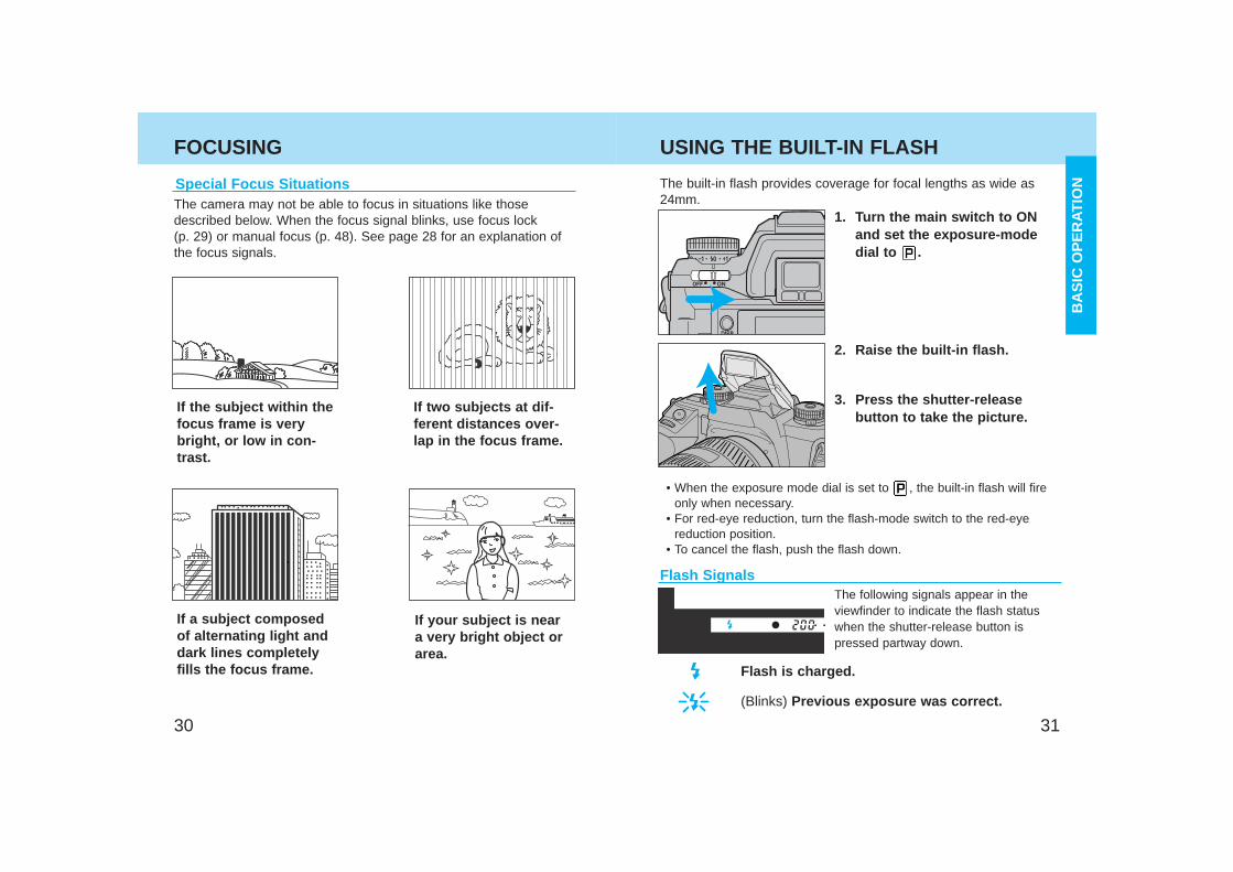
FOCUSING USING THE BUILT-IN FLASH
The built-in flash provides coverage for focal lengths as wide as24mm.
1. Turn the main switch to ONand set the exposure-modedial to .
2. Raise the built-in flash.
3. Press the shutter-releasebutton to take the picture.
• When the exposure mode dial is set to , the built-in flash will fireonly when necessary.
• For red-eye reduction, turn the flash-mode switch to the red-eyereduction position.
• To cancel the flash, push the flash down.
The following signals appear in theviewfinder to indicate the flash statuswhen the shutter-release button ispressed partway down.
Flash is charged.
(Blinks) Previous exposure was correct.
Special Focus SituationsThe camera may not be able to focus in situations like thosedescribed below. When the focus signal blinks, use focus lock (p. 29) or manual focus (p. 48). See page 28 for an explanation ofthe focus signals.
If the subject within thefocus frame is verybright, or low in con-trast.
If two subjects at dif-ferent distances over-lap in the focus frame.
If a subject composedof alternating light anddark lines completelyfills the focus frame.
If your subject is neara very bright object orarea.
Flash Signals
BA
SIC
OP
ER
ATIO
N
3332
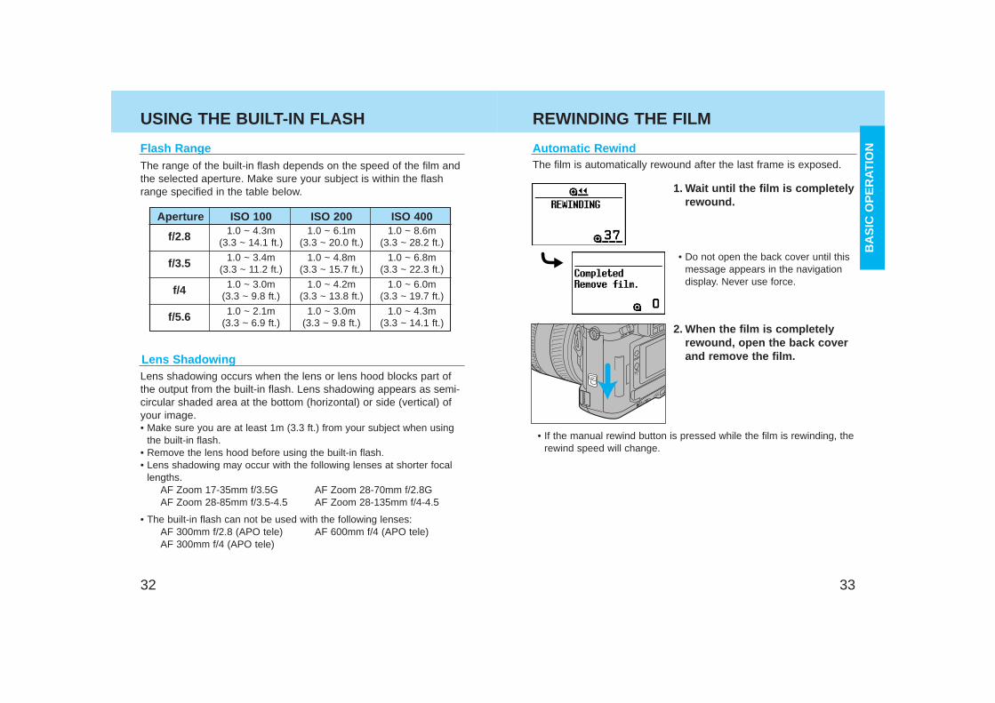
Automatic RewindThe film is automatically rewound after the last frame is exposed.
1. Wait until the film is completelyrewound.
2. When the film is completelyrewound, open the back coverand remove the film.
Flash RangeThe range of the built-in flash depends on the speed of the film andthe selected aperture. Make sure your subject is within the flashrange specified in the table below.
Aperture ISO 100 ISO 200 ISO 400
f/2.8
f/3.5
f/4
f/5.6
1.0 ~ 4.3m 1.0 ~ 6.1m 1.0 ~ 8.6m(3.3 ~ 14.1 ft.) (3.3 ~ 20.0 ft.) (3.3 ~ 28.2 ft.)
1.0 ~ 3.4m 1.0 ~ 4.8m 1.0 ~ 6.8m(3.3 ~ 11.2 ft.) (3.3 ~ 15.7 ft.) (3.3 ~ 22.3 ft.)
1.0 ~ 3.0m 1.0 ~ 4.2m 1.0 ~ 6.0m(3.3 ~ 9.8 ft.) (3.3 ~ 13.8 ft.) (3.3 ~ 19.7 ft.)
1.0 ~ 2.1m 1.0 ~ 3.0m 1.0 ~ 4.3m(3.3 ~ 6.9 ft.) (3.3 ~ 9.8 ft.) (3.3 ~ 14.1 ft.)
Lens ShadowingLens shadowing occurs when the lens or lens hood blocks part ofthe output from the built-in flash. Lens shadowing appears as semi-circular shaded area at the bottom (horizontal) or side (vertical) ofyour image.• Make sure you are at least 1m (3.3 ft.) from your subject when using
the built-in flash.• Remove the lens hood before using the built-in flash.• Lens shadowing may occur with the following lenses at shorter focal
lengths.AF Zoom 17-35mm f/3.5G AF Zoom 28-70mm f/2.8GAF Zoom 28-85mm f/3.5-4.5 AF Zoom 28-135mm f/4-4.5
• The built-in flash can not be used with the following lenses:AF 300mm f/2.8 (APO tele) AF 600mm f/4 (APO tele)AF 300mm f/4 (APO tele)
• Do not open the back cover until thismessage appears in the navigationdisplay. Never use force.
USING THE BUILT-IN FLASH REWINDING THE FILM
• If the manual rewind button is pressed while the film is rewinding, therewind speed will change.
BA
SIC
OP
ER
ATIO
N
3534
REWINDING THE FILM
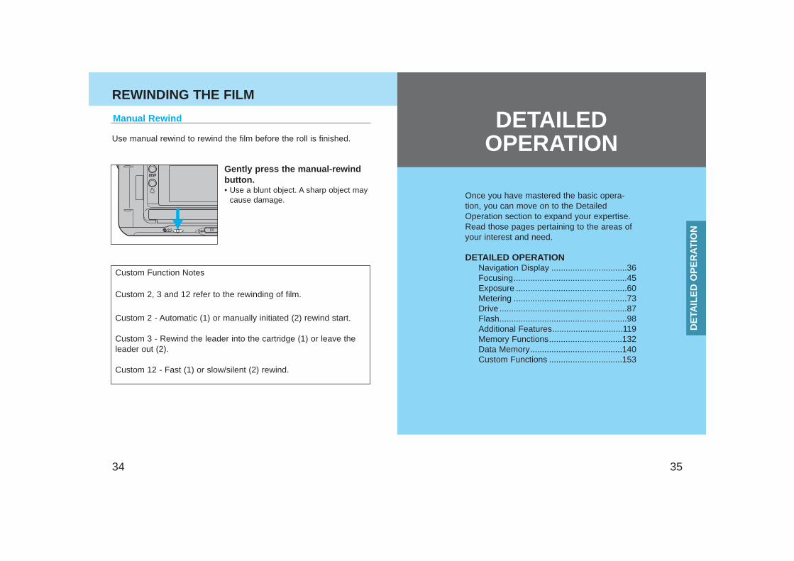
Manual Rewind
Use manual rewind to rewind the film before the roll is finished.
Gently press the manual-rewindbutton.• Use a blunt object. A sharp object may
cause damage.
Custom Function Notes
Custom 2, 3 and 12 refer to the rewinding of film.
Custom 2 - Automatic (1) or manually initiated (2) rewind start.
Custom 3 - Rewind the leader into the cartridge (1) or leave theleader out (2).
Custom 12 - Fast (1) or slow/silent (2) rewind.
Once you have mastered the basic opera-tion, you can move on to the DetailedOperation section to expand your expertise.Read those pages pertaining to the areas ofyour interest and need.
DETAILED OPERATIONNavigation Display ................................36Focusing................................................45Exposure ...............................................60Metering ................................................73Drive ......................................................87Flash......................................................98Additional Features..............................119Memory Functions...............................132Data Memory.......................................140Custom Functions ...............................153
DE
TAIL
ED
OP
ER
ATIO
N
DETAILEDOPERATION
3736
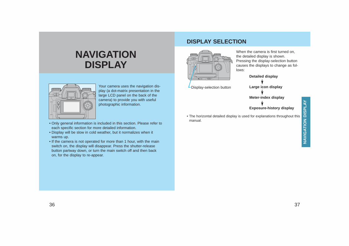
Your camera uses the navigation dis-play (a dot-matrix presentation in thelarge LCD panel on the back of thecamera) to provide you with usefulphotographic information.
• Only general information is included in this section. Please refer toeach specific section for more detailed information.
• Display will be slow in cold weather, but it normalizes when itwarms up.
• If the camera is not operated for more than 1 hour, with the mainswitch on, the display will disappear. Press the shutter-releasebutton partway down, or turn the main switch off and then backon, for the display to re-appear.
Exposure-history display
Display-selection button
When the camera is first turned on,the detailed display is shown.Pressing the display-selection buttoncauses the displays to change as fol-lows:
• The horizontal detailed display is used for explanations throughout thismanual.
Detailed display
Large icon display
Meter-index display
DISPLAY SELECTION
NAV
IGAT
ION
DIS
PLA
Y
NAVIGATIONDISPLAY
3938
DISPLAY SELECTION
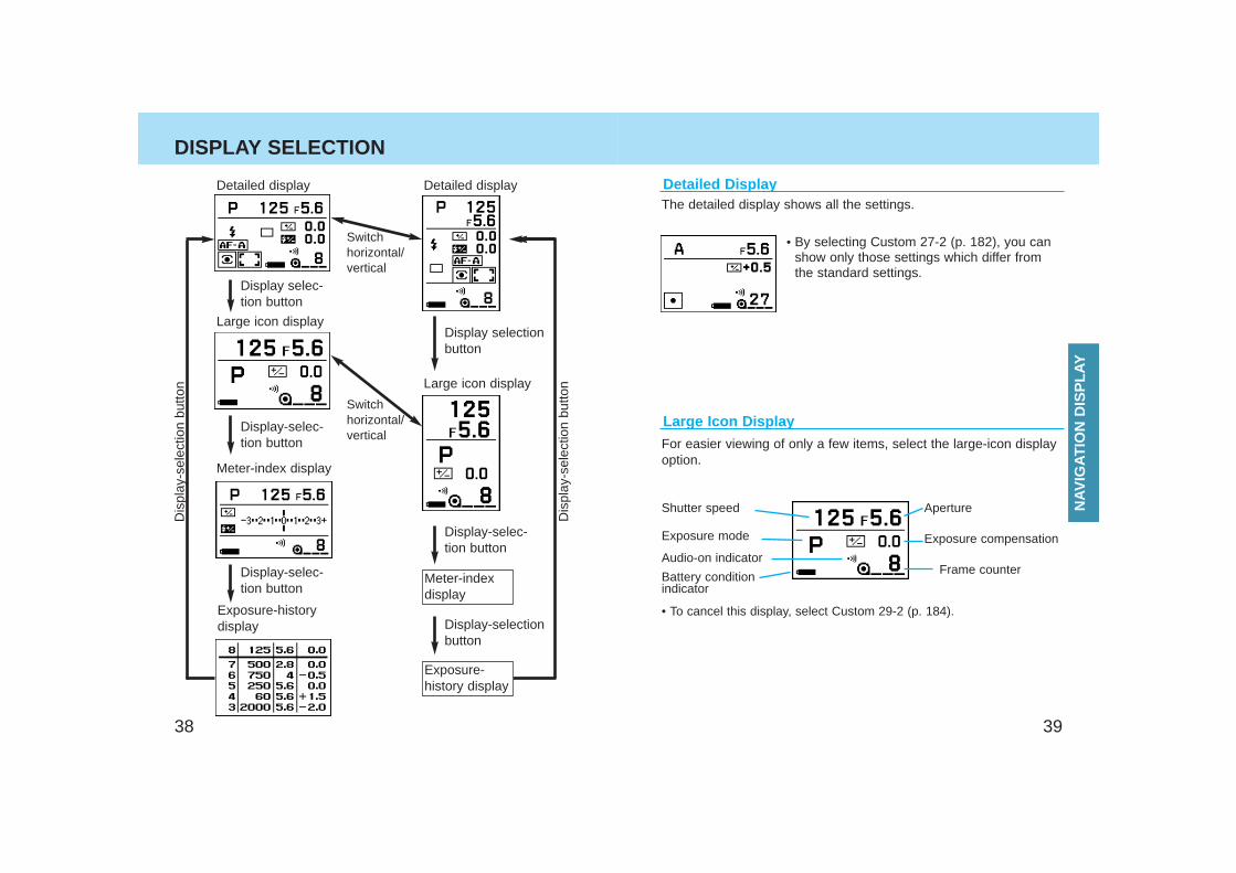
Detailed display Detailed display
Exposure-historydisplay
Meter-index display
Large icon display
Large icon display
Meter-indexdisplay
Exposure-history display
Display-selec-tion button
Display-selectionbutton
Switch horizontal/vertical
Switch horizontal/vertical
Display selec-tion button
Display-selec-tion button
Display-selec-tion button
Display selectionbutton
The detailed display shows all the settings.
• By selecting Custom 27-2 (p. 182), you canshow only those settings which differ fromthe standard settings.
Detailed Display
For easier viewing of only a few items, select the large-icon displayoption.
• To cancel this display, select Custom 29-2 (p. 184).
Aperture
Exposure compensation
Frame counter
Large Icon Display
Shutter speed
Exposure mode
Audio-on indicator
Battery conditionindicator
NAV
IGAT
ION
DIS
PLA
Y
Dis
play
-sel
ectio
n bu
tton
Dis
play
-sel
ectio
n bu
tton
4140
DISPLAY SELECTION
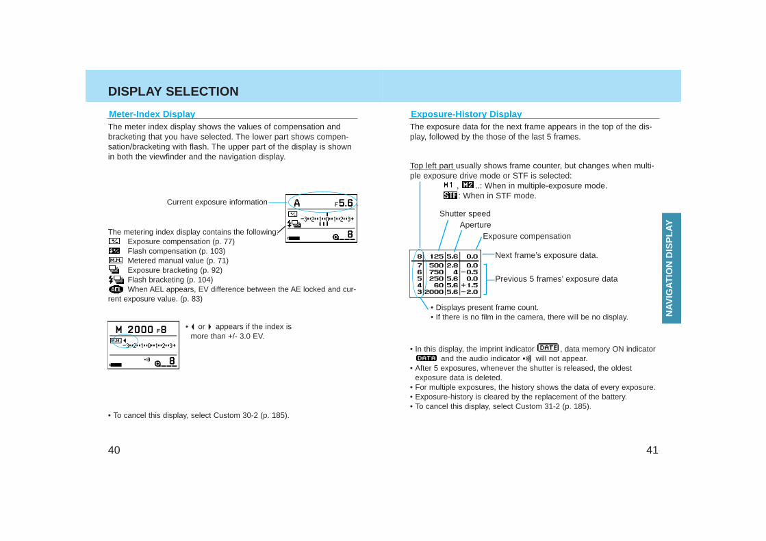
The meter index display shows the values of compensation andbracketing that you have selected. The lower part shows compen-sation/bracketing with flash. The upper part of the display is shownin both the viewfinder and the navigation display.
Meter-Index Display
Current exposure information
The metering index display contains the following:Exposure compensation (p. 77)Flash compensation (p. 103)Metered manual value (p. 71)Exposure bracketing (p. 92)Flash bracketing (p. 104)When AEL appears, EV difference between the AE locked and cur-
rent exposure value. (p. 83)
• To cancel this display, select Custom 30-2 (p. 185).
• or appears if the index ismore than +/- 3.0 EV.
Exposure-History DisplayThe exposure data for the next frame appears in the top of the dis-play, followed by the those of the last 5 frames.
Exposure compensation
Next frame’s exposure data.
Previous 5 frames’ exposure data
ApertureShutter speed
• Displays present frame count.• If there is no film in the camera, there will be no display.
• In this display, the imprint indicator , data memory ON indicatorand the audio indicator will not appear.
• After 5 exposures, whenever the shutter is released, the oldestexposure data is deleted.
• For multiple exposures, the history shows the data of every exposure.• Exposure-history is cleared by the replacement of the battery.• To cancel this display, select Custom 31-2 (p. 185).
Top left part usually shows frame counter, but changes when multi-ple exposure drive mode or STF is selected:
, ..: When in multiple-exposure mode.: When in STF mode.
NAV
IGAT
ION
DIS
PLA
Y
4342
DISPLAY SELECTION
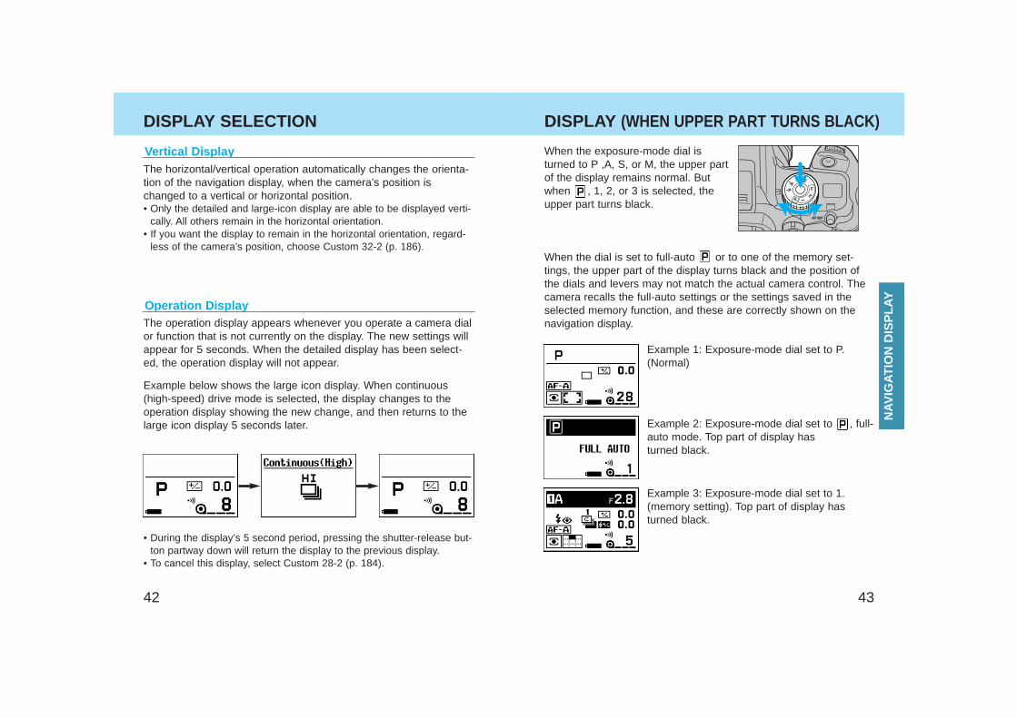
When the exposure-mode dial isturned to P ,A, S, or M, the upper partof the display remains normal. Butwhen , 1, 2, or 3 is selected, theupper part turns black.
Example 1: Exposure-mode dial set to P.(Normal)
Example 2: Exposure-mode dial set to , full-auto mode. Top part of display hasturned black.
Example 3: Exposure-mode dial set to 1.(memory setting). Top part of display hasturned black.
When the dial is set to full-auto or to one of the memory set-tings, the upper part of the display turns black and the position ofthe dials and levers may not match the actual camera control. Thecamera recalls the full-auto settings or the settings saved in theselected memory function, and these are correctly shown on thenavigation display.
Vertical Display
Operation Display
• During the display’s 5 second period, pressing the shutter-release but-ton partway down will return the display to the previous display.
• To cancel this display, select Custom 28-2 (p. 184).
The horizontal/vertical operation automatically changes the orienta-tion of the navigation display, when the camera’s position ischanged to a vertical or horizontal position.• Only the detailed and large-icon display are able to be displayed verti-
cally. All others remain in the horizontal orientation.• If you want the display to remain in the horizontal orientation, regard-
less of the camera’s position, choose Custom 32-2 (p. 186).
The operation display appears whenever you operate a camera dialor function that is not currently on the display. The new settings willappear for 5 seconds. When the detailed display has been select-ed, the operation display will not appear.
Example below shows the large icon display. When continuous(high-speed) drive mode is selected, the display changes to theoperation display showing the new change, and then returns to thelarge icon display 5 seconds later.
DISPLAY (WHEN UPPER PART TURNS BLACK)
NAV
IGAT
ION
DIS
PLA
Y
4544
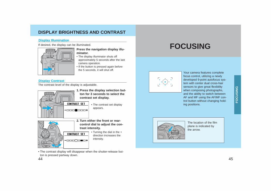
Your camera features completefocus control, utilizing a newlydeveloped 9-point autofocus sys-tem with center dual cross-hairsensors to give great flexibilitywhen composing photographs,and the ability to switch betweenAF and MF using the AF/MF con-trol button without changing hold-ing positions.
Display Illumination
Display Contrast
If desired, the display can be illuminated.
Press the navigation display illu-minator.• The display illuminator shuts off
approximately 5 seconds after the lastcamera operation.
• If the button is pressed again beforethe 5 seconds, it will shut off.
The contrast level of the display is adjustable.
• The contrast set displayappears.
• Turning the dial in the +direction increases theintensity.
• The contrast display will disappear when the shutter-release but-ton is pressed partway down.
1. Press the display selection but-ton for 3 seconds to select thecontrast set display.
2. Turn either the front or rear-control dial to adjust the con-trast intensity.
The location of the filmplane is indicated bythe arrow.
DISPLAY BRIGHTNESS AND CONTRAST
FO
CU
SIN
G
FOCUSING
4746
FOCUS MODE
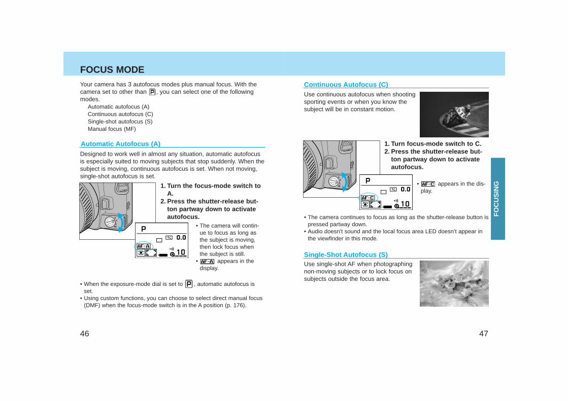
Continuous Autofocus (C)Use continuous autofocus when shootingsporting events or when you know thesubject will be in constant motion.
• The camera continues to focus as long as the shutter-release button ispressed partway down.
• Audio doesn’t sound and the local focus area LED doesn’t appear inthe viewfinder in this mode.
Use single-shot AF when photographingnon-moving subjects or to lock focus onsubjects outside the focus area.
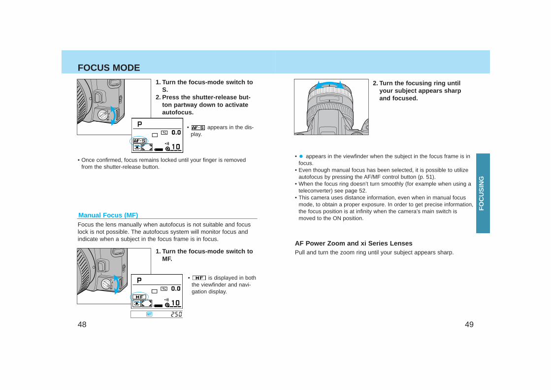
1. Turn focus-mode switch to C.2. Press the shutter-release but-
ton partway down to activateautofocus.
• appears in the dis-play.
Single-Shot Autofocus (S)
Your camera has 3 autofocus modes plus manual focus. With thecamera set to other than , you can select one of the followingmodes.
Automatic autofocus (A)Continuous autofocus (C)Single-shot autofocus (S)Manual focus (MF)
Automatic Autofocus (A)Designed to work well in almost any situation, automatic autofocusis especially suited to moving subjects that stop suddenly. When thesubject is moving, continuous autofocus is set. When not moving,single-shot autofocus is set.
1. Turn the focus-mode switch toA.
2. Press the shutter-release but-ton partway down to activateautofocus.
• When the exposure-mode dial is set to , automatic autofocus isset.
• Using custom functions, you can choose to select direct manual focus(DMF) when the focus-mode switch is in the A position (p. 176).
• The camera will contin-ue to focus as long asthe subject is moving,then lock focus whenthe subject is still.
• appears in thedisplay.
FO
CU
SIN
G
4948
FOCUS MODE
• appears in the viewfinder when the subject in the focus frame is infocus.
• Even though manual focus has been selected, it is possible to utilizeautofocus by pressing the AF/MF control button (p. 51).
• When the focus ring doesn’t turn smoothly (for example when using ateleconverter) see page 52.
• This camera uses distance information, even when in manual focusmode, to obtain a proper exposure. In order to get precise information,the focus position is at infinity when the camera’s main switch ismoved to the ON position.
2. Turn the focusing ring untilyour subject appears sharpand focused.
Pull and turn the zoom ring until your subject appears sharp.
AF Power Zoom and xi Series Lenses
1. Turn the focus-mode switch toS.
2. Press the shutter-release but-ton partway down to activateautofocus.
Manual Focus (MF)Focus the lens manually when autofocus is not suitable and focuslock is not possible. The autofocus system will monitor focus andindicate when a subject in the focus frame is in focus.
1. Turn the focus-mode switch toMF.
• is displayed in boththe viewfinder and navi-gation display.
• appears in the dis-play.
• Once confirmed, focus remains locked until your finger is removedfrom the shutter-release button.
FO
CU
SIN
G
5150
AF/MF CONTROL BUTTON
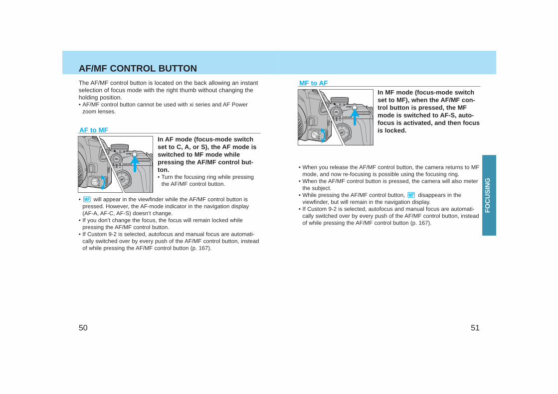
In MF mode (focus-mode switchset to MF), when the AF/MF con-trol button is pressed, the MFmode is switched to AF-S, auto-focus is activated, and then focusis locked.
• When you release the AF/MF control button, the camera returns to MFmode, and now re-focusing is possible using the focusing ring.
• When the AF/MF control button is pressed, the camera will also meterthe subject.
• While pressing the AF/MF control button, disappears in theviewfinder, but will remain in the navigation display.
• If Custom 9-2 is selected, autofocus and manual focus are automati-cally switched over by every push of the AF/MF control button, insteadof while pressing the AF/MF control button (p. 167).
AF to MF In AF mode (focus-mode switchset to C, A, or S), the AF mode isswitched to MF mode whilepressing the AF/MF control but-ton.• Turn the focusing ring while pressing
the AF/MF control button.
• will appear in the viewfinder while the AF/MF control button ispressed. However, the AF-mode indicator in the navigation display(AF-A, AF-C, AF-S) doesn’t change.
• If you don’t change the focus, the focus will remain locked whilepressing the AF/MF control button.
• If Custom 9-2 is selected, autofocus and manual focus are automati-cally switched over by every push of the AF/MF control button, insteadof while pressing the AF/MF control button (p. 167).
The AF/MF control button is located on the back allowing an instantselection of focus mode with the right thumb without changing theholding position.• AF/MF control button cannot be used with xi series and AF Power
zoom lenses.
MF to AF
FO
CU
SIN
G
5352
FOCUS AREA
Wide focus area
Local focus area
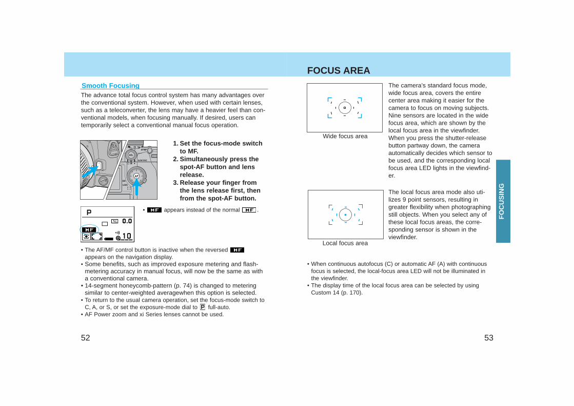
The camera’s standard focus mode,wide focus area, covers the entirecenter area making it easier for thecamera to focus on moving subjects.Nine sensors are located in the widefocus area, which are shown by thelocal focus area in the viewfinder.When you press the shutter-releasebutton partway down, the cameraautomatically decides which sensor tobe used, and the corresponding localfocus area LED lights in the viewfind-er.
The local focus area mode also uti-lizes 9 point sensors, resulting ingreater flexibility when photographingstill objects. When you select any ofthese local focus areas, the corre-sponding sensor is shown in theviewfinder.
• When continuous autofocus (C) or automatic AF (A) with continuousfocus is selected, the local-focus area LED will not be illuminated inthe viewfinder.
• The display time of the local focus area can be selected by usingCustom 14 (p. 170).
The advance total focus control system has many advantages overthe conventional system. However, when used with certain lenses,such as a teleconverter, the lens may have a heavier feel than con-ventional models, when focusing manually. If desired, users cantemporarily select a conventional manual focus operation.
1. Set the focus-mode switchto MF.
2. Simultaneously press thespot-AF button and lensrelease.
3. Release your finger fromthe lens release first, thenfrom the spot-AF button.
• appears instead of the normal .
• The AF/MF control button is inactive when the reversed appears on the navigation display.
• Some benefits, such as improved exposure metering and flash-metering accuracy in manual focus, will now be the same as witha conventional camera.
• 14-segment honeycomb-pattern (p. 74) is changed to meteringsimilar to center-weighted averagewhen this option is selected.
• To return to the usual camera operation, set the focus-mode switch toC, A, or S, or set the exposure-mode dial to full-auto.
• AF Power zoom and xi Series lenses cannot be used.
Smooth Focusing
FO
CU
SIN
G
5554
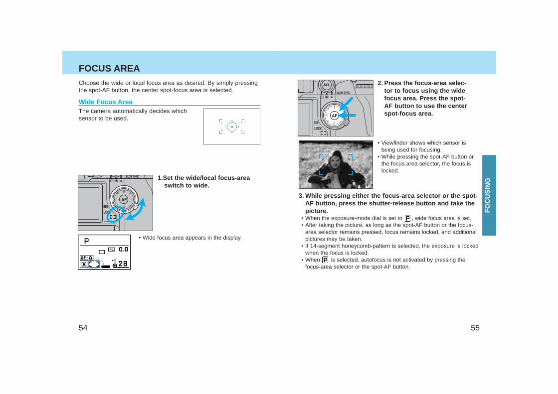
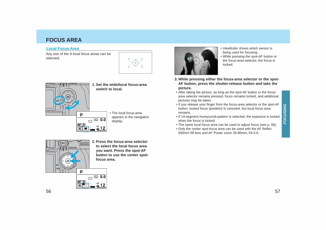
FOCUS AREA2. Press the focus-area selec-
tor to focus using the widefocus area. Press the spot-AF button to use the centerspot-focus area.
• Viewfinder shows which sensor isbeing used for focusing.
• While pressing the spot-AF button orthe focus-area selector, the focus islocked.
3. While pressing either the focus-area selector or the spot-AF button, press the shutter-release button and take thepicture.
• When the exposure-mode dial is set to , wide focus area is set.• After taking the picture, as long as the spot-AF button or the focus-
area selector remains pressed, focus remains locked, and additionalpictures may be taken.
• If 14-segment honeycomb-pattern is selected, the exposure is lockedwhen the focus is locked.
• When is selected, autofocus is not activated by pressing thefocus-area selector or the spot-AF button.
Choose the wide or local focus area as desired. By simply pressingthe spot-AF button, the center spot-focus area is selected.
Wide Focus AreaThe camera automatically decides whichsensor to be used.
1.Set the wide/local focus-areaswitch to wide.
• Wide focus area appears in the display.
FO
CU
SIN
G
5756
FOCUS AREA• Viewfinder shows which sensor is
being used for focusing.• While pressing the spot-AF button or
the focus-area selector, the focus islocked.
3. While pressing either the focus-area selector or the spot-AF button, press the shutter-release button and take thepicture.
• After taking the picture, as long as the spot-AF button or the focus-area selector remains pressed, focus remains locked, and additionalpictures may be taken.
• If you release your finger from the focus-area selector or the spot-AFbutton, locked focus (position) is canceled, but local focus arearemains.
• If 14-segment honeycomb-pattern is selected, the exposure is lockedwhen the focus is locked.
• The same local focus area can be used to adjust focus (see p. 58).• Only the center spot-focus area can be used with the AF Reflex
500mm f/8 lens and AF Power zoom 35-80mm, f/4-5.6.
Local Focus AreaAny one of the 9 local focus areas can beselected.
1. Set the wide/local focus-areaswitch to local.
• The local focus-areaappears in the navigationdisplay.
2. Press the focus-area selectorto select the local focus areayou want. Press the spot-AFbutton to use the center spot-focus area.
FO
CU
SIN
G
5958
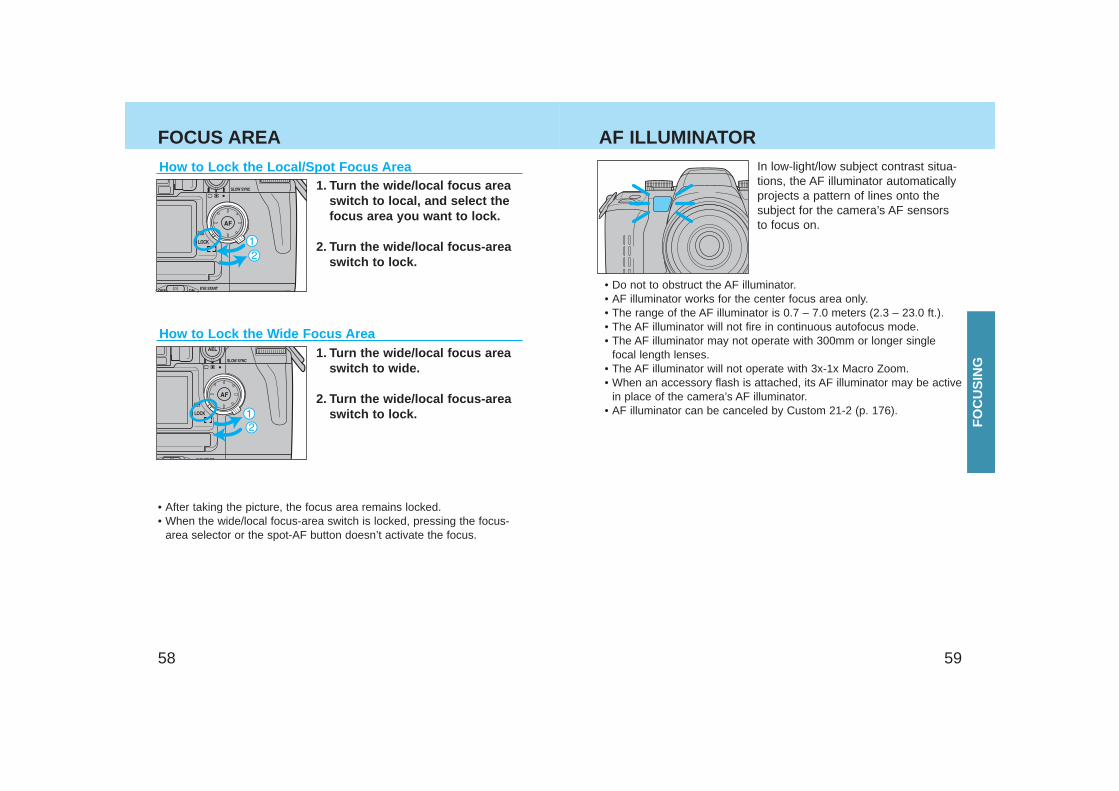
FOCUS AREAIn low-light/low subject contrast situa-tions, the AF illuminator automaticallyprojects a pattern of lines onto thesubject for the camera’s AF sensorsto focus on.
• Do not to obstruct the AF illuminator.• AF illuminator works for the center focus area only.• The range of the AF illuminator is 0.7 – 7.0 meters (2.3 – 23.0 ft.).• The AF illuminator will not fire in continuous autofocus mode.• The AF illuminator may not operate with 300mm or longer single
focal length lenses.• The AF illuminator will not operate with 3x-1x Macro Zoom.• When an accessory flash is attached, its AF illuminator may be active
in place of the camera’s AF illuminator.• AF illuminator can be canceled by Custom 21-2 (p. 176).
How to Lock the Local/Spot Focus Area1. Turn the wide/local focus area
switch to local, and select thefocus area you want to lock.
2. Turn the wide/local focus-areaswitch to lock.
• After taking the picture, the focus area remains locked.• When the wide/local focus-area switch is locked, pressing the focus-
area selector or the spot-AF button doesn’t activate the focus.
AF ILLUMINATOR
How to Lock the Wide Focus Area1. Turn the wide/local focus area
switch to wide.
2. Turn the wide/local focus-areaswitch to lock.
FO
CU
SIN
G
6160
EXPOSURE
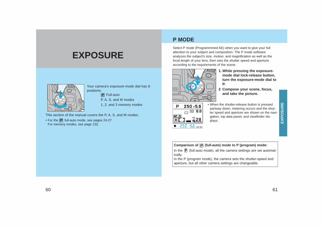
Your camera’s exposure-mode dial has 8positions;
Full-auto P, A, S, and M modes1, 2, and 3 memory modes
This section of the manual covers the P, A, S, and M modes.
• For the full-auto mode, see pages 24-27.For memory modes, see page 132.
Select P mode (Programmmed AE) when you want to give your fullattention to your subject and composition. The P mode softwareanalyzes the subject’s size, motion, and magnification as well as thefocal length of your lens, then sets the shutter speed and apertureaccording to the requirements of the scene.
1. While pressing the exposure-mode dial lock-release button,turn the exposure-mode dial toP.
2 Compose your scene, focus,and take the picture.
• When the shutter-release button is pressedpartway down, metering occurs and the shut-ter speed and aperture are shown on the navi-gation, top data panel, and viewfinder dis-plays.
P MODE
Comparison of (full-auto) mode to P (program) mode:
In the (full-auto mode), all the camera settings are set automat-ically. In the P (program mode), the camera sets the shutter-speed andaperture, but all other camera settings are changeable.
EX
PO
SU
RE
6362
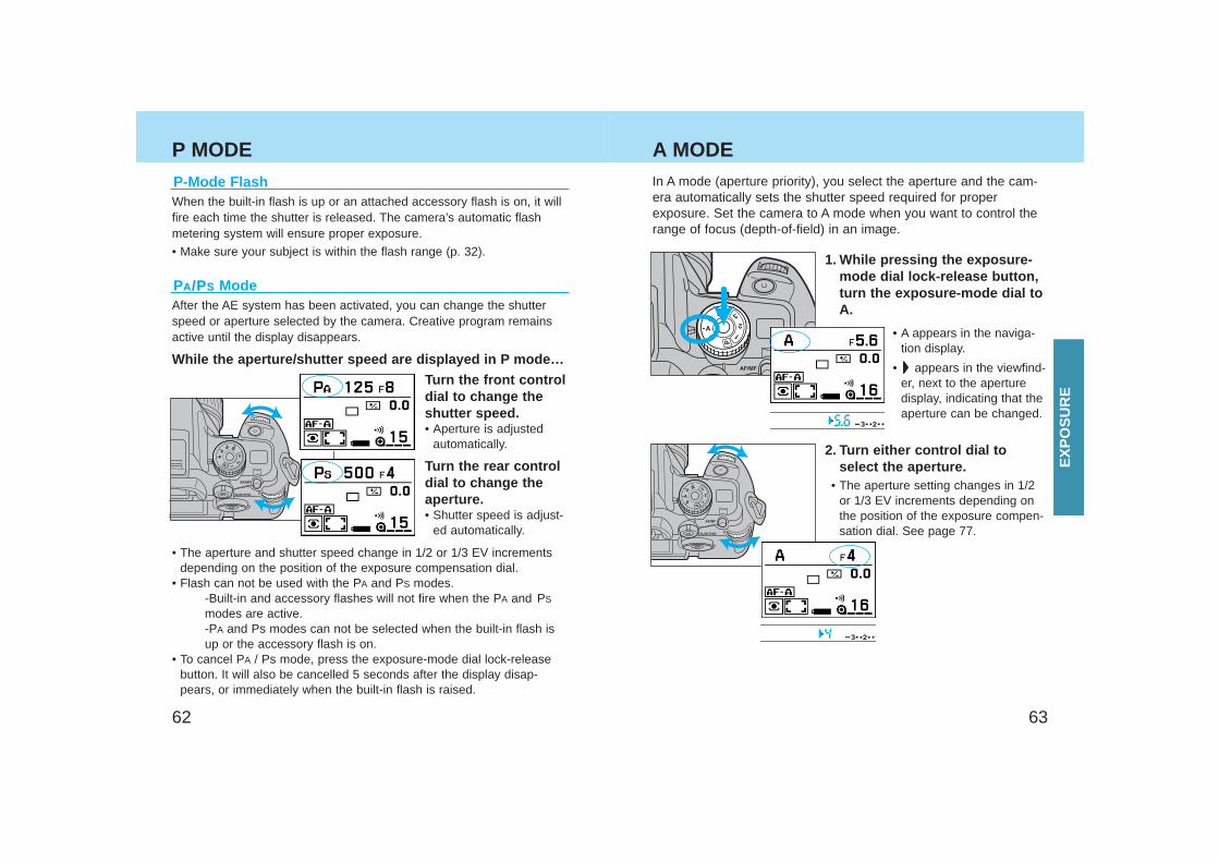
P MODE A MODEIn A mode (aperture priority), you select the aperture and the cam-era automatically sets the shutter speed required for properexposure. Set the camera to A mode when you want to control therange of focus (depth-of-field) in an image.
1. While pressing the exposure-mode dial lock-release button,turn the exposure-mode dial toA.
• A appears in the naviga-tion display.
• appears in the viewfind-er, next to the aperturedisplay, indicating that theaperture can be changed.
2. Turn either control dial toselect the aperture.
• The aperture setting changes in 1/2or 1/3 EV increments depending onthe position of the exposure compen-sation dial. See page 77.
PAA /P/PSS ModeAfter the AE system has been activated, you can change the shutterspeed or aperture selected by the camera. Creative program remainsactive until the display disappears.
Turn the front controldial to change theshutter speed.• Aperture is adjusted
automatically.
Turn the rear controldial to change theaperture.• Shutter speed is adjust-
ed automatically.
While the aperture/shutter speed are displayed in P mode…
• The aperture and shutter speed change in 1/2 or 1/3 EV incrementsdepending on the position of the exposure compensation dial.
• Flash can not be used with the PA and PS modes.-Built-in and accessory flashes will not fire when the PA and PS
modes are active.-PA and Ps modes can not be selected when the built-in flash is up or the accessory flash is on.
• To cancel PA / Ps mode, press the exposure-mode dial lock-releasebutton. It will also be cancelled 5 seconds after the display disap-pears, or immediately when the built-in flash is raised.
When the built-in flash is up or an attached accessory flash is on, it willfire each time the shutter is released. The camera’s automatic flashmetering system will ensure proper exposure.
• Make sure your subject is within the flash range (p. 32).
P-Mode Flash
EX
PO
SU
RE
6564
A MODE
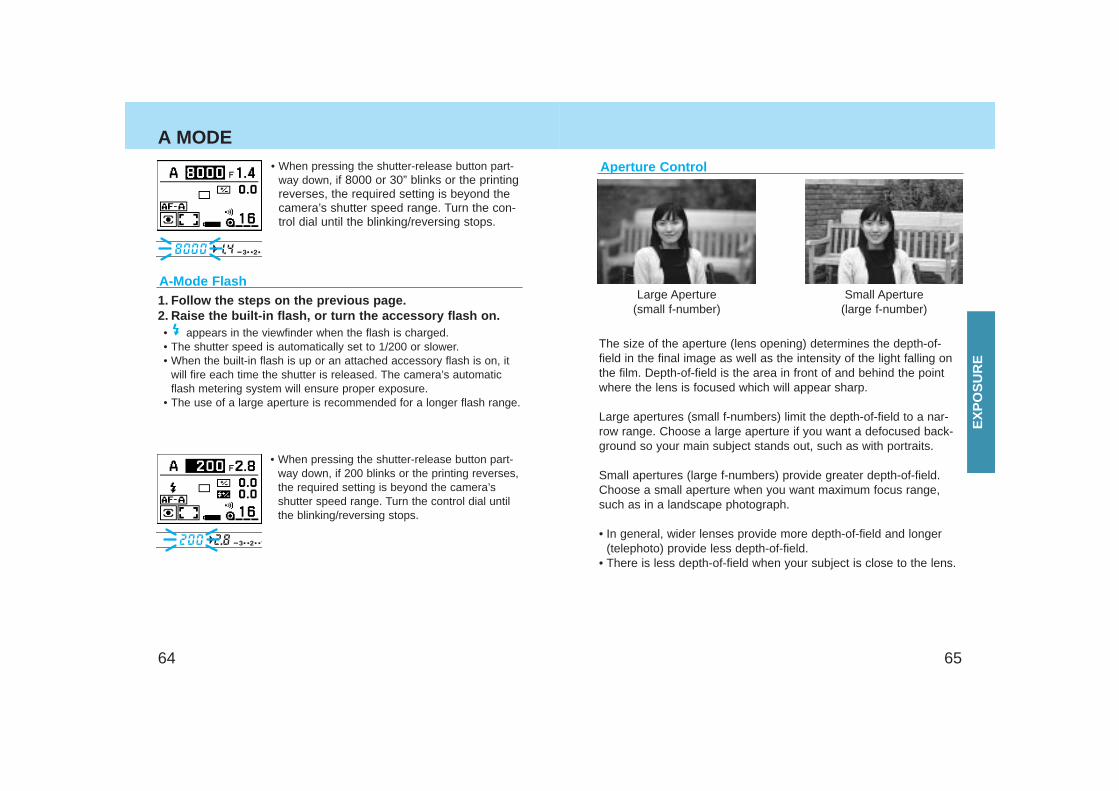
The size of the aperture (lens opening) determines the depth-of-field in the final image as well as the intensity of the light falling onthe film. Depth-of-field is the area in front of and behind the pointwhere the lens is focused which will appear sharp.
Large apertures (small f-numbers) limit the depth-of-field to a nar-row range. Choose a large aperture if you want a defocused back-ground so your main subject stands out, such as with portraits.
Small apertures (large f-numbers) provide greater depth-of-field.Choose a small aperture when you want maximum focus range,such as in a landscape photograph.
• In general, wider lenses provide more depth-of-field and longer(telephoto) provide less depth-of-field.
• There is less depth-of-field when your subject is close to the lens.
Large Aperture(small f-number)
Small Aperture(large f-number)
Aperture Control
A-Mode Flash1. Follow the steps on the previous page.2. Raise the built-in flash, or turn the accessory flash on.• appears in the viewfinder when the flash is charged.• The shutter speed is automatically set to 1/200 or slower.• When the built-in flash is up or an attached accessory flash is on, it
will fire each time the shutter is released. The camera’s automaticflash metering system will ensure proper exposure.
• The use of a large aperture is recommended for a longer flash range.
• When pressing the shutter-release button part-way down, if 200 blinks or the printing reverses,the required setting is beyond the camera’sshutter speed range. Turn the control dial untilthe blinking/reversing stops.
• When pressing the shutter-release button part-way down, if 8000 or 30” blinks or the printingreverses, the required setting is beyond thecamera’s shutter speed range. Turn the con-trol dial until the blinking/reversing stops.
EX
PO
SU
RE
6766
S MODEIn S mode (shutter priority), you select the shutter speed and thecamera automatically sets the aperture for the proper exposure.Use S mode when you want to control the blur caused by subjectmovement.
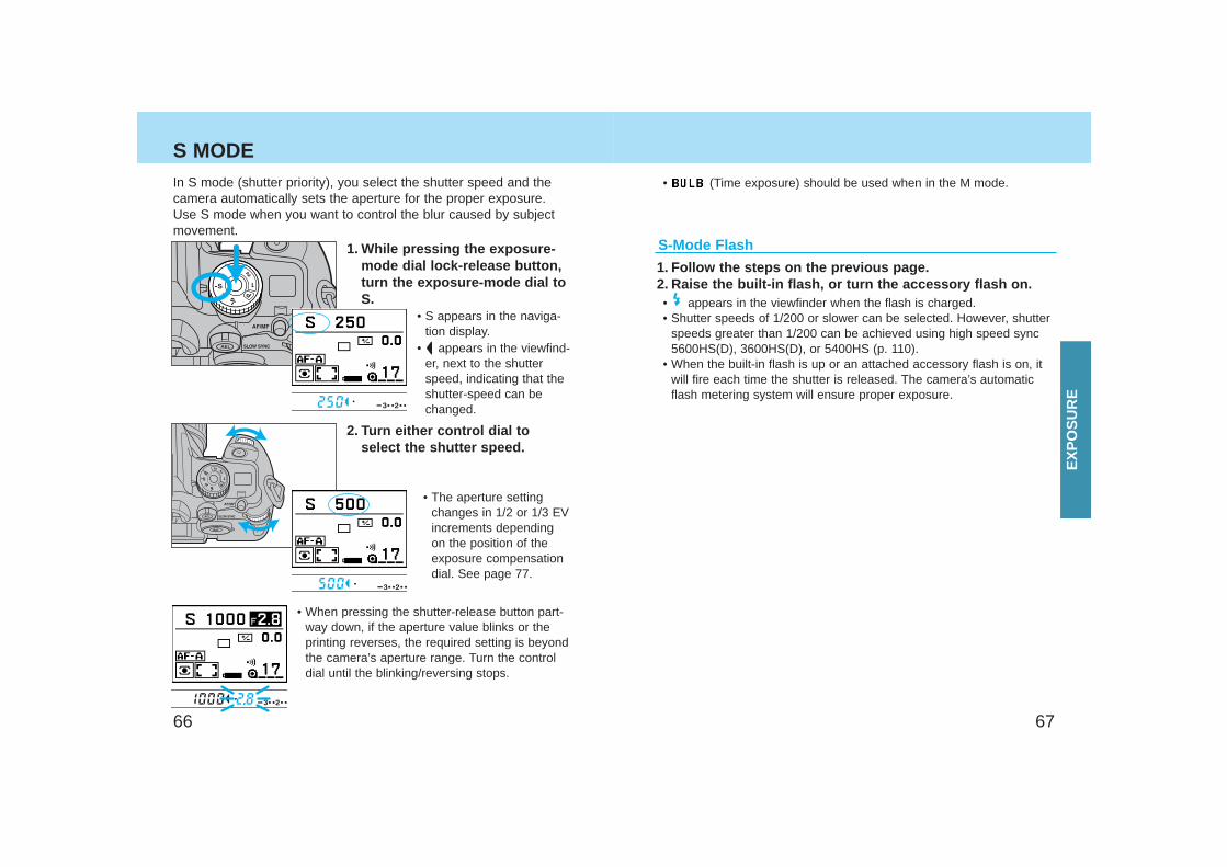
1. While pressing the exposure-mode dial lock-release button,turn the exposure-mode dial toS.
• S appears in the naviga-tion display.
• appears in the viewfind-er, next to the shutterspeed, indicating that theshutter-speed can bechanged.
2. Turn either control dial toselect the shutter speed.
• The aperture settingchanges in 1/2 or 1/3 EVincrements dependingon the position of theexposure compensationdial. See page 77.
• When pressing the shutter-release button part-way down, if the aperture value blinks or theprinting reverses, the required setting is beyondthe camera’s aperture range. Turn the controldial until the blinking/reversing stops.
1. Follow the steps on the previous page.2. Raise the built-in flash, or turn the accessory flash on.• appears in the viewfinder when the flash is charged.• Shutter speeds of 1/200 or slower can be selected. However, shutter
speeds greater than 1/200 can be achieved using high speed sync5600HS(D), 3600HS(D), or 5400HS (p. 110).
• When the built-in flash is up or an attached accessory flash is on, itwill fire each time the shutter is released. The camera’s automaticflash metering system will ensure proper exposure.
S-Mode Flash
• (Time exposure) should be used when in the M mode.
EX
PO
SU
RE
6968
S MODE M MODE
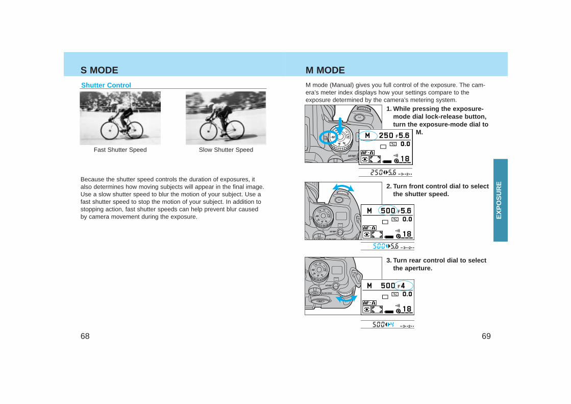
Fast Shutter Speed Slow Shutter Speed
Because the shutter speed controls the duration of exposures, italso determines how moving subjects will appear in the final image.Use a slow shutter speed to blur the motion of your subject. Use afast shutter speed to stop the motion of your subject. In addition tostopping action, fast shutter speeds can help prevent blur causedby camera movement during the exposure.
Shutter Control M mode (Manual) gives you full control of the exposure. The cam-era’s meter index displays how your settings compare to theexposure determined by the camera’s metering system.
1. While pressing the exposure-mode dial lock-release button,turn the exposure-mode dial to
M.
2. Turn front control dial to selectthe shutter speed.
3. Turn rear control dial to selectthe aperture.
EX
PO
SU
RE
7170
M-Mode Flash1. Follow the steps on the previous page.2. Raise the built-in flash, or turn the accessory flash on.• appears in the viewfinder when the flash is charged.• The shutter speeds of 1/200 or slower are selectable. However, shut-
ter speeds greater than 1/200 can be achieved using high speedsync flash 5600HS(D), 3600HS(D), or 5400HS (p. 110).
• When the built-in flash is up or an attached accessory flash is on, itwill fire each time the shutter is released. The camera’s automaticflash metering system will ensure proper exposure.
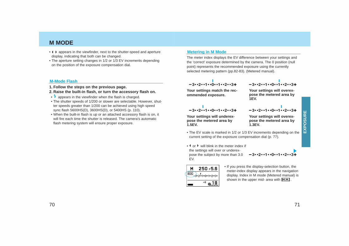
Metering in M ModeThe meter index displays the EV difference between your settings andthe ‘correct’ exposure determined by the camera. The 0 position (nullpoint) represents the recommended exposure using the currentlyselected metering pattern (pp.82-83). (Metered manual).
Your settings match the rec-ommended exposure.
Your settings will overex-pose the metered area by1EV.
Your settings will overex-pose the metered area by1.3EV.
Your settings will underex-pose the metered area by1.5EV.
• The EV scale is marked in 1/2 or 1/3 EV increments depending on thecurrent setting of the exposure compensation dial (p. 77).
• or will blink in the meter index ifthe settings will over or underex-pose the subject by more than 3.0EV.
• If you press the display-selection button, themeter-index display appears in the navigationdisplay. Index in M mode (Metered manual) isshown in the upper mid- area with .
M MODE• appears in the viewfinder, next to the shutter-speed and aperture
display, indicating that both can be changed.• The aperture setting changes in 1/2 or 1/3 EV increments depending
on the position of the exposure compensation dial.
EX
PO
SU
RE
7372
M MODE
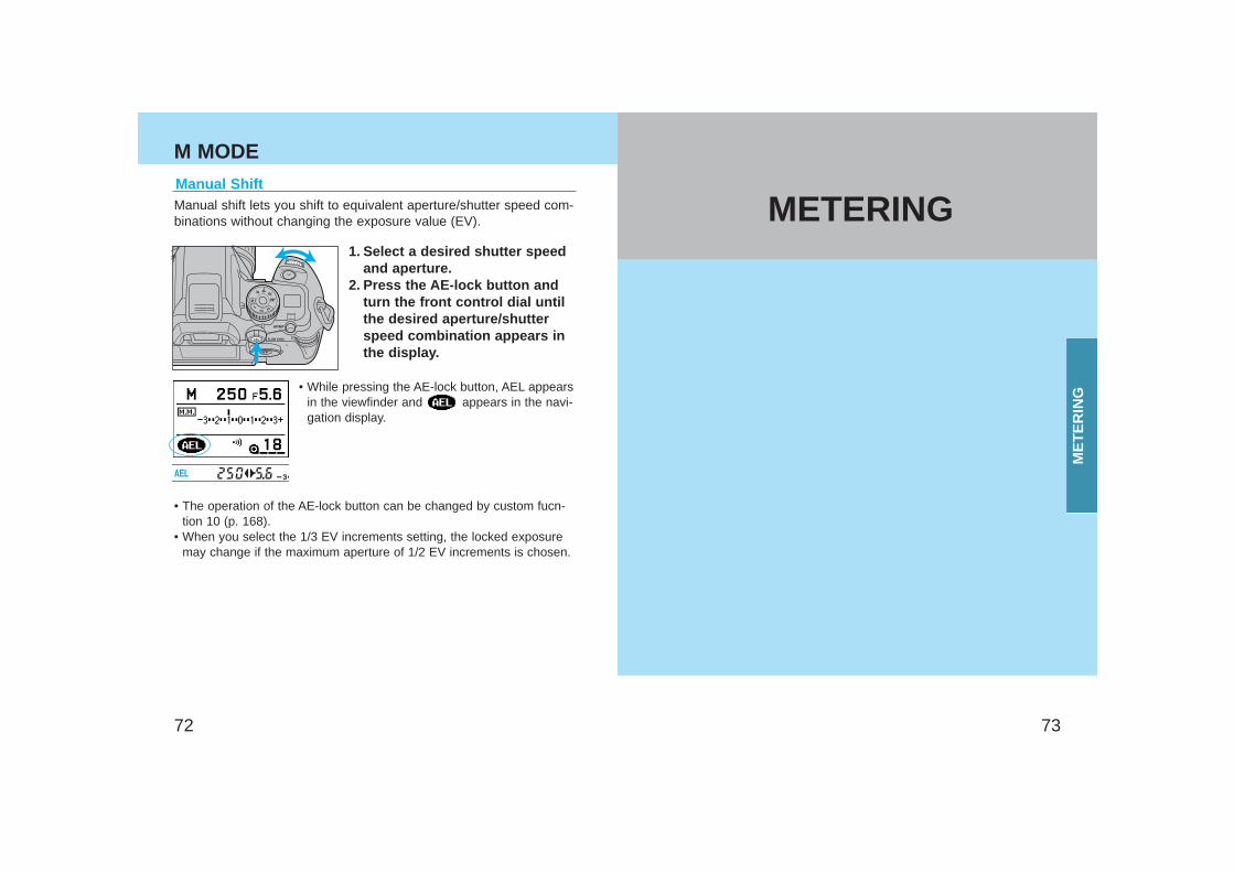
Manual ShiftManual shift lets you shift to equivalent aperture/shutter speed com-binations without changing the exposure value (EV).
1. Select a desired shutter speedand aperture.
2. Press the AE-lock button andturn the front control dial untilthe desired aperture/shutterspeed combination appears inthe display.
• While pressing the AE-lock button, AEL appearsin the viewfinder and appears in the navi-gation display.
• The operation of the AE-lock button can be changed by custom fucn-tion 10 (p. 168).
• When you select the 1/3 EV increments setting, the locked exposuremay change if the maximum aperture of 1/2 EV increments is chosen.
METERING
ME
TE
RIN
G
7574
SELECTABLE METERING
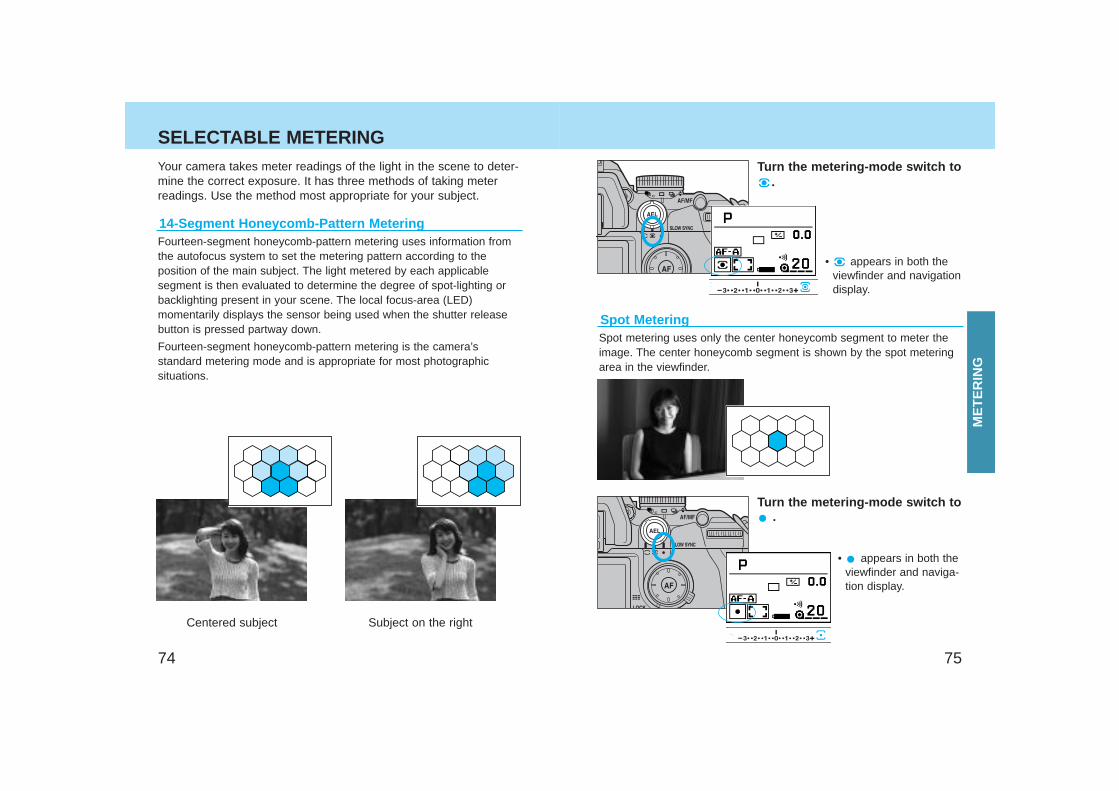
Fourteen-segment honeycomb-pattern metering uses information fromthe autofocus system to set the metering pattern according to theposition of the main subject. The light metered by each applicablesegment is then evaluated to determine the degree of spot-lighting orbacklighting present in your scene. The local focus-area (LED)momentarily displays the sensor being used when the shutter releasebutton is pressed partway down.
Fourteen-segment honeycomb-pattern metering is the camera’sstandard metering mode and is appropriate for most photographicsituations.
14-Segment Honeycomb-Pattern Metering
Centered subject Subject on the right
Your camera takes meter readings of the light in the scene to deter-mine the correct exposure. It has three methods of taking meterreadings. Use the method most appropriate for your subject.
Turn the metering-mode switch to.
• appears in both theviewfinder and navigationdisplay.
Spot MeteringSpot metering uses only the center honeycomb segment to meter theimage. The center honeycomb segment is shown by the spot meteringarea in the viewfinder.
Turn the metering-mode switch to.
• appears in both theviewfinder and naviga-tion display.
ME
TE
RIN
G
7776
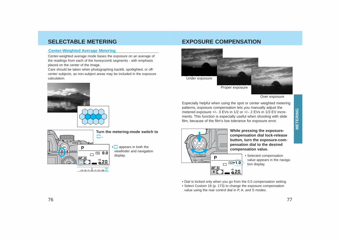
Center-Weighted Average MeteringCenter-weighted average mode bases the exposure on an average ofthe readings from each of the honeycomb segments - with emphasisplaced on the center of the image.Care should be taken when photographing backlit, spotlighted, or off-center subjects, as non-subject areas may be included in the exposurecalculation.
• appears in both theviewfinder and navigationdisplay.
Turn the metering-mode switch to.
Especially helpful when using the spot or center weighted meteringpatterns, exposure compensation lets you manually adjust themetered exposure +/– 3 EVs in 1/2 or +/– 2 EVs in 1/3 EV incre-ments. This function is especially useful when shooting with slidefilm, because of the film’s low tolerance for exposure error.
Under exposure
Proper exposure
Over exposure
• Dial is locked only when you go from the 0.0 compensation setting.• Select Custom 18 (p. 173) to change the exposure compensation
value using the rear control dial in P, A, and S modes.
• Selected compensationvalue appears in the naviga-tion display.
While pressing the exposure-compensation dial lock-releasebutton, turn the exposure-com-pensation dial to the desiredcompensation value.
SELECTABLE METERING EXPOSURE COMPENSATION
ME
TE
RIN
G
7978
EXPOSURE COMPENSATION
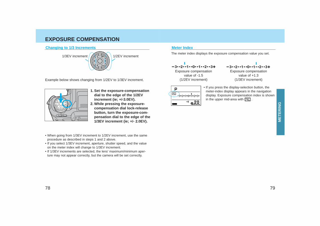
Changing to 1/3 Increments
1. Set the exposure-compensationdial to the edge of the 1/2EVincrement (ie; +/-3.0EV).
2. While pressing the exposure-compensation dial lock-releasebutton, turn the exposure-com-pensation dial to the edge of the1/3EV increment (ie; +/- 2.0EV).
1/3EV increment 1/2EV increment
Example below shows changing from 1/2EV to 1/3EV increment.
• When going from 1/3EV increment to 1/2EV increment, use the sameprocedure as described in steps 1 and 2 above.
• If you select 1/3EV increment, aperture, shutter speed, and the valueon the meter index will change to 1/3EV increment.
• If 1/3EV increments are selected, the lens’ maximum/minimum aper-ture may not appear correctly, but the camera will be set correctly.
Exposure compensationvalue of -1.5
(1/2EV increment)
Exposure compensationvalue of +1.3
(1/3EV increment)
• If you press the display-selection button, themeter-index display appears in the navigationdisplay. Exposure compensation index is shownin the upper mid-area with .
Meter IndexThe meter index displays the exposure compensation value you set.
ME
TE
RIN
G
8180
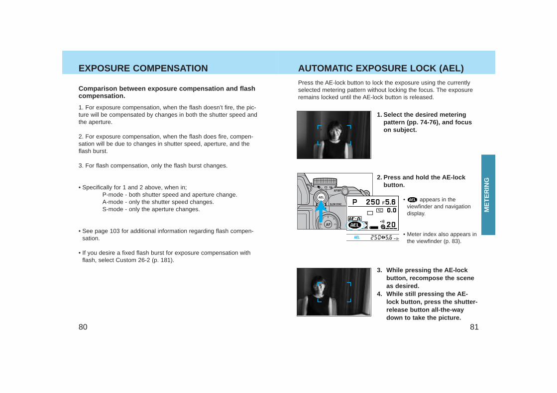
EXPOSURE COMPENSATION AUTOMATIC EXPOSURE LOCK (AEL) Press the AE-lock button to lock the exposure using the currentlyselected metering pattern without locking the focus. The exposureremains locked until the AE-lock button is released.
1. Select the desired meteringpattern (pp. 74-76), and focuson subject.
• appears in theviewfinder and navigationdisplay.
• Meter index also appears inthe viewfinder (p. 83).
2. Press and hold the AE-lockbutton.
1. For exposure compensation, when the flash doesn’t fire, the pic-ture will be compensated by changes in both the shutter speed andthe aperture.
2. For exposure compensation, when the flash does fire, compen-sation will be due to changes in shutter speed, aperture, and theflash burst.
3. For flash compensation, only the flash burst changes.
• Specifically for 1 and 2 above, when in;P-mode - both shutter speed and aperture change.A-mode - only the shutter speed changes.S-mode - only the aperture changes.
• See page 103 for additional information regarding flash compen-sation.
• If you desire a fixed flash burst for exposure compensation withflash, select Custom 26-2 (p. 181).
Comparison between exposure compensation and flashcompensation.
3. While pressing the AE-lockbutton, recompose the sceneas desired.
4. While still pressing the AE-lock button, press the shutter-release button all-the-waydown to take the picture.
ME
TE
RIN
G
8382
AUTOMATIC EXPOSURE LOCK (AEL) • If you keep pressing the AE-lock button after taking the picture, the
exposure remains locked.• Pressing the AE-lock button sets the flash to slow-shutter sync mode
(p. 102).• If Custom 10-2 is selected, pressing the AE-lock button once activates
automatic exposure lock. Pressing again cancels.
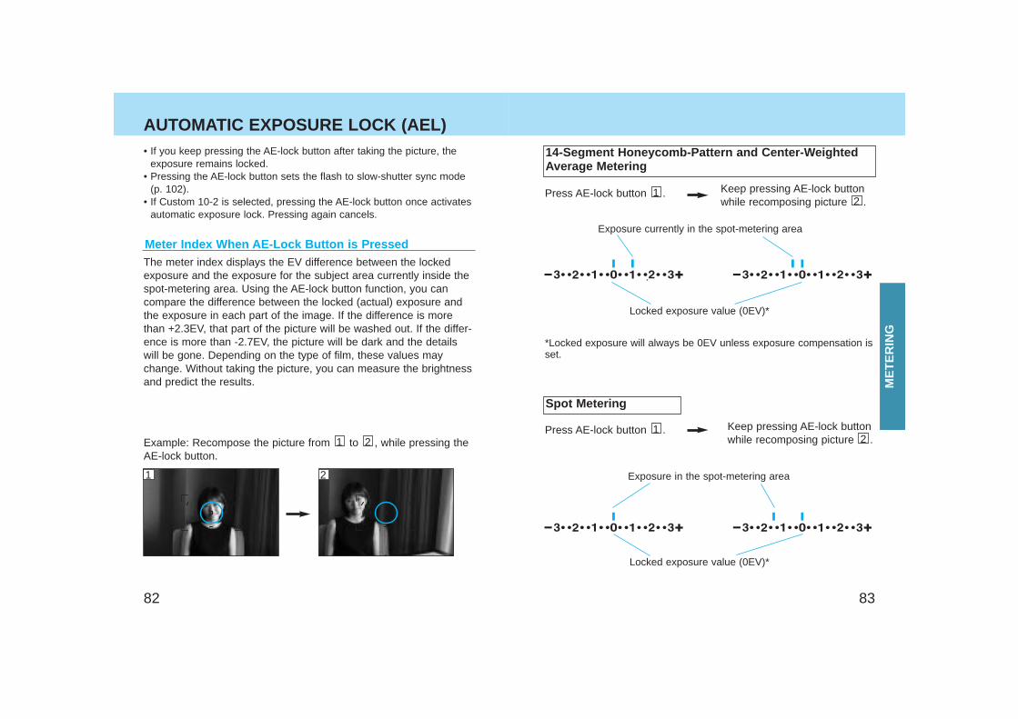
Meter Index When AE-Lock Button is PressedThe meter index displays the EV difference between the lockedexposure and the exposure for the subject area currently inside thespot-metering area. Using the AE-lock button function, you cancompare the difference between the locked (actual) exposure andthe exposure in each part of the image. If the difference is morethan +2.3EV, that part of the picture will be washed out. If the differ-ence is more than -2.7EV, the picture will be dark and the detailswill be gone. Depending on the type of film, these values maychange. Without taking the picture, you can measure the brightnessand predict the results.
Spot Metering
Example: Recompose the picture from to , while pressing theAE-lock button.
21Press AE-lock button .1 Keep pressing AE-lock button
while recomposing picture .2
14-Segment Honeycomb-Pattern and Center-WeightedAverage Metering
Press AE-lock button .1 Keep pressing AE-lock buttonwhile recomposing picture .2
*Locked exposure will always be 0EV unless exposure compensation isset.
Locked exposure value (0EV)*
Locked exposure value (0EV)*
Exposure currently in the spot-metering area
Exposure in the spot-metering area
ME
TE
RIN
G
21
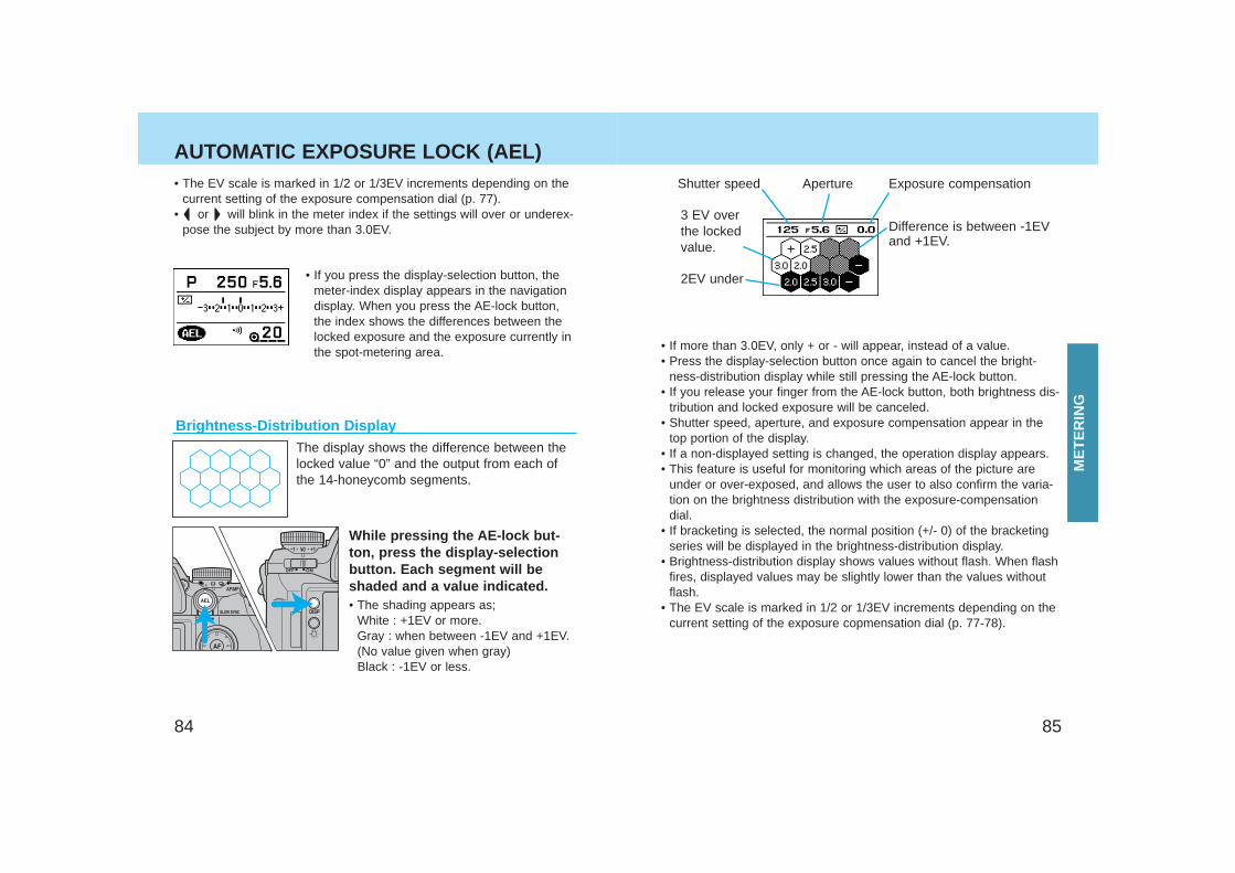
• If more than 3.0EV, only + or - will appear, instead of a value.• Press the display-selection button once again to cancel the bright-
ness-distribution display while still pressing the AE-lock button.• If you release your finger from the AE-lock button, both brightness dis-
tribution and locked exposure will be canceled.• Shutter speed, aperture, and exposure compensation appear in the
top portion of the display.• If a non-displayed setting is changed, the operation display appears.• This feature is useful for monitoring which areas of the picture are
under or over-exposed, and allows the user to also confirm the varia-tion on the brightness distribution with the exposure-compensationdial.
• If bracketing is selected, the normal position (+/- 0) of the bracketingseries will be displayed in the brightness-distribution display.
• Brightness-distribution display shows values without flash. When flashfires, displayed values may be slightly lower than the values withoutflash.
• The EV scale is marked in 1/2 or 1/3EV increments depending on thecurrent setting of the exposure copmensation dial (p. 77-78).
8584
AUTOMATIC EXPOSURE LOCK (AEL)
Brightness-Distribution Display
While pressing the AE-lock but-ton, press the display-selectionbutton. Each segment will beshaded and a value indicated. • The shading appears as;
White : +1EV or more.Gray : when between -1EV and +1EV.(No value given when gray)Black : -1EV or less.
The display shows the difference between thelocked value “0” and the output from each ofthe 14-honeycomb segments.
• If you press the display-selection button, themeter-index display appears in the navigationdisplay. When you press the AE-lock button,the index shows the differences between thelocked exposure and the exposure currently inthe spot-metering area.
• The EV scale is marked in 1/2 or 1/3EV increments depending on thecurrent setting of the exposure compensation dial (p. 77).
• or will blink in the meter index if the settings will over or underex-pose the subject by more than 3.0EV.
Shutter speed Aperture
Difference is between -1EVand +1EV.
2EV under
Exposure compensation
3 EV overthe lockedvalue.
ME
TE
RIN
G
8786
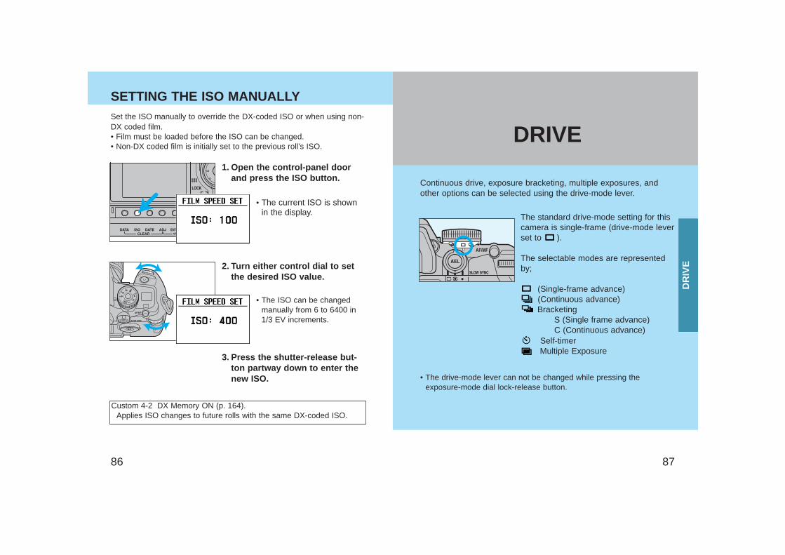
SETTING THE ISO MANUALLY
Continuous drive, exposure bracketing, multiple exposures, andother options can be selected using the drive-mode lever.
The standard drive-mode setting for thiscamera is single-frame (drive-mode leverset to ).
The selectable modes are representedby;
(Single-frame advance)(Continuous advance)Bracketing
S (Single frame advance)C (Continuous advance)
Self-timerMultiple Exposure
Set the ISO manually to override the DX-coded ISO or when using non-DX coded film.• Film must be loaded before the ISO can be changed.• Non-DX coded film is initially set to the previous roll’s ISO.
1. Open the control-panel doorand press the ISO button.
• The current ISO is shownin the display.
• The ISO can be changedmanually from 6 to 6400 in1/3 EV increments.
2. Turn either control dial to setthe desired ISO value.
3. Press the shutter-release but-ton partway down to enter thenew ISO.
Custom 4-2 DX Memory ON (p. 164).Applies ISO changes to future rolls with the same DX-coded ISO.
• The drive-mode lever can not be changed while pressing theexposure-mode dial lock-release button.
DRIVE
DR
IVE
8988
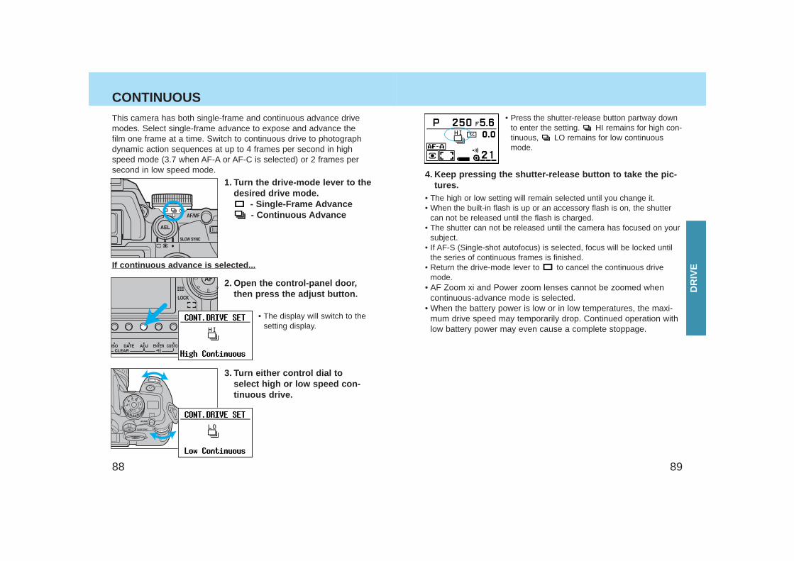
CONTINUOUSThis camera has both single-frame and continuous advance drivemodes. Select single-frame advance to expose and advance thefilm one frame at a time. Switch to continuous drive to photographdynamic action sequences at up to 4 frames per second in highspeed mode (3.7 when AF-A or AF-C is selected) or 2 frames persecond in low speed mode.
1. Turn the drive-mode lever to thedesired drive mode.
- Single-Frame Advance- Continuous Advance
2. Open the control-panel door,then press the adjust button.
• The display will switch to thesetting display.
3. Turn either control dial toselect high or low speed con-tinuous drive.
4. Keep pressing the shutter-release button to take the pic-tures.
• The high or low setting will remain selected until you change it.• When the built-in flash is up or an accessory flash is on, the shutter
can not be released until the flash is charged.• The shutter can not be released until the camera has focused on your
subject.• If AF-S (Single-shot autofocus) is selected, focus will be locked until
the series of continuous frames is finished.• Return the drive-mode lever to to cancel the continuous drive
mode.• AF Zoom xi and Power zoom lenses cannot be zoomed when
continuous-advance mode is selected.• When the battery power is low or in low temperatures, the maxi-
mum drive speed may temporarily drop. Continued operation withlow battery power may even cause a complete stoppage.
• Press the shutter-release button partway downto enter the setting. HI remains for high con-tinuous, LO remains for low continuousmode.
If continuous advance is selected...
DR
IVE
9190
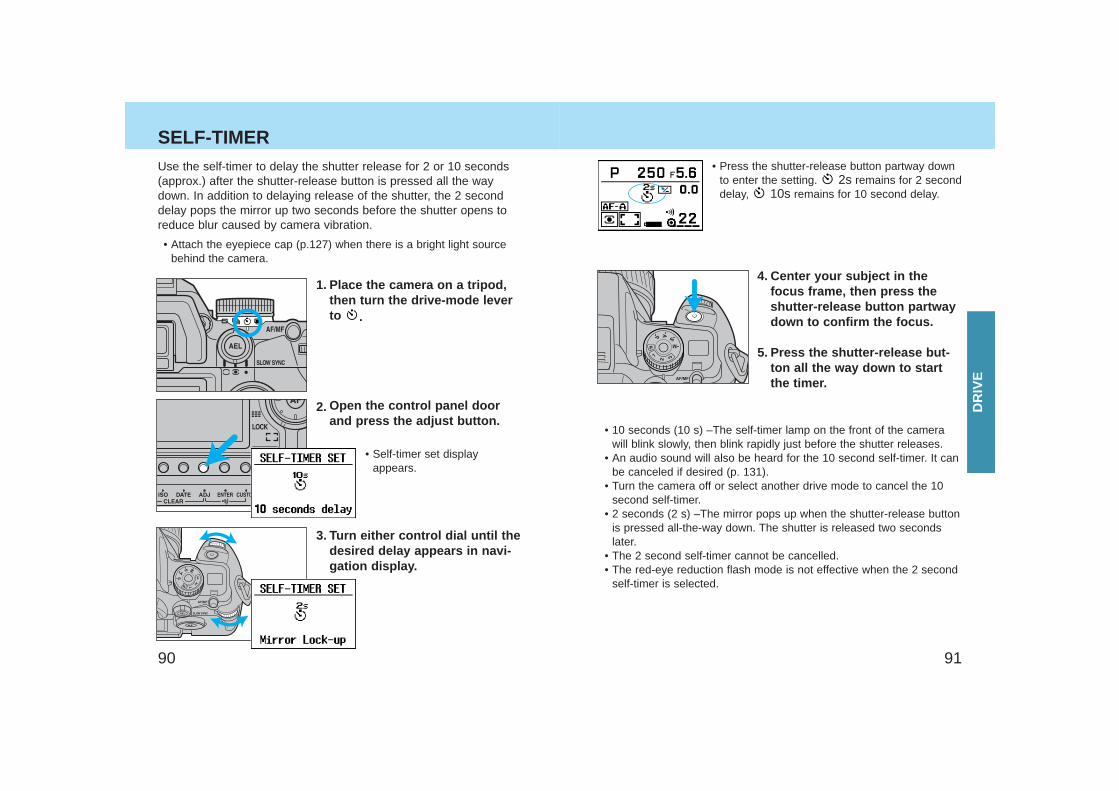
SELF-TIMER Use the self-timer to delay the shutter release for 2 or 10 seconds(approx.) after the shutter-release button is pressed all the waydown. In addition to delaying release of the shutter, the 2 seconddelay pops the mirror up two seconds before the shutter opens toreduce blur caused by camera vibration.
• Attach the eyepiece cap (p.127) when there is a bright light sourcebehind the camera.
1. Place the camera on a tripod,then turn the drive-mode leverto .
• Self-timer set displayappears.
4. Center your subject in thefocus frame, then press theshutter-release button partwaydown to confirm the focus.
5. Press the shutter-release but-ton all the way down to startthe timer.
• 10 seconds (10 s) –The self-timer lamp on the front of the camerawill blink slowly, then blink rapidly just before the shutter releases.
• An audio sound will also be heard for the 10 second self-timer. It canbe canceled if desired (p. 131).
• Turn the camera off or select another drive mode to cancel the 10second self-timer.
• 2 seconds (2 s) –The mirror pops up when the shutter-release buttonis pressed all-the-way down. The shutter is released two secondslater.
• The 2 second self-timer cannot be cancelled.• The red-eye reduction flash mode is not effective when the 2 second
self-timer is selected.
2. Open the control panel doorand press the adjust button.
3. Turn either control dial until thedesired delay appears in navi-gation display.
• Press the shutter-release button partway downto enter the setting. 2s remains for 2 seconddelay, 10s remains for 10 second delay.
DR
IVE
9392
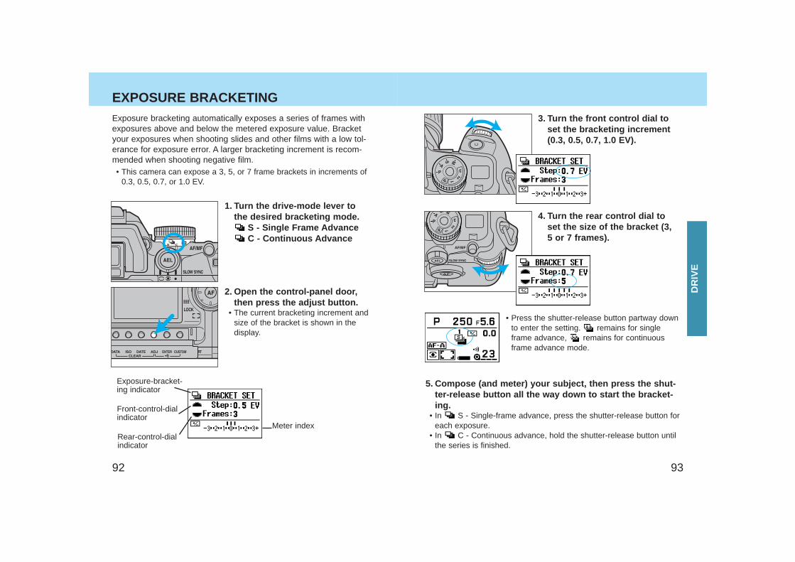
EXPOSURE BRACKETING Exposure bracketing automatically exposes a series of frames withexposures above and below the metered exposure value. Bracketyour exposures when shooting slides and other films with a low tol-erance for exposure error. A larger bracketing increment is recom-mended when shooting negative film.• This camera can expose a 3, 5, or 7 frame brackets in increments of
0.3, 0.5, 0.7, or 1.0 EV.
1. Turn the drive-mode lever tothe desired bracketing mode.
S - Single Frame AdvanceC - Continuous Advance
2. Open the control-panel door,then press the adjust button.
• The current bracketing increment andsize of the bracket is shown in thedisplay.
3. Turn the front control dial toset the bracketing increment(0.3, 0.5, 0.7, 1.0 EV).
4. Turn the rear control dial toset the size of the bracket (3,5 or 7 frames).
• Press the shutter-release button partway downto enter the setting. remains for singleframe advance, remains for continuousframe advance mode.
5. Compose (and meter) your subject, then press the shut-ter-release button all the way down to start the bracket-ing.
• In S - Single-frame advance, press the shutter-release button foreach exposure.
• In C - Continuous advance, hold the shutter-release button untilthe series is finished.
Exposure-bracket-ing indicator
Front-control-dialindicator
Meter indexRear-control-dialindicator
DR
IVE
9594
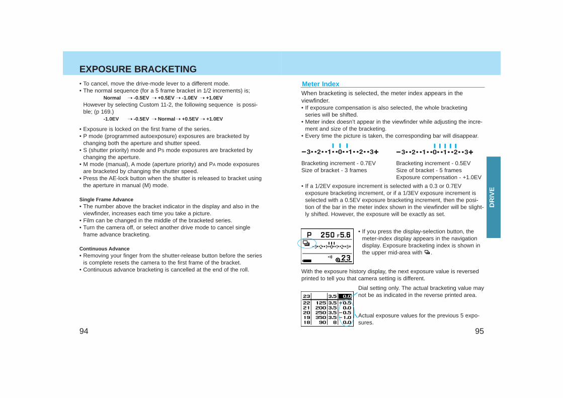
EXPOSURE BRACKETING
When bracketing is selected, the meter index appears in theviewfinder.• If exposure compensation is also selected, the whole bracketing
series will be shifted.• Meter index doesn’t appear in the viewfinder while adjusting the incre-
ment and size of the bracketing.• Every time the picture is taken, the corresponding bar will disappear.
• To cancel, move the drive-mode lever to a different mode.• The normal sequence (for a 5 frame bracket in 1/2 increments) is;
Normal ➝ -0.5EV ➝ +0.5EV ➝ -1.0EV ➝ +1.0EVHowever by selecting Custom 11-2, the following sequence is possi-ble; (p 169.)
-1.0EV ➝ -0.5EV ➝ Normal ➝ +0.5EV ➝ +1.0EV
• Exposure is locked on the first frame of the series.• P mode (programmed autoexposure) exposures are bracketed by
changing both the aperture and shutter speed.• S (shutter priority) mode and PS mode exposures are bracketed by
changing the aperture.• M mode (manual), A mode (aperture priority) and PA mode exposures
are bracketed by changing the shutter speed.• Press the AE-lock button when the shutter is released to bracket using
the aperture in manual (M) mode.
Single Frame Advance• The number above the bracket indicator in the display and also in the
viewfinder, increases each time you take a picture.• Film can be changed in the middle of the bracketed series.• Turn the camera off, or select another drive mode to cancel single
frame advance bracketing.
Continuous Advance• Removing your finger from the shutter-release button before the series
is complete resets the camera to the first frame of the bracket.• Continuous advance bracketing is cancelled at the end of the roll.
Meter Index
Bracketing increment - 0.7EVSize of bracket - 3 frames
Bracketing increment - 0.5EVSize of bracket - 5 framesExposure compensation - +1.0EV
• If a 1/2EV exposure increment is selected with a 0.3 or 0.7EVexposure bracketing increment, or if a 1/3EV exposure increment isselected with a 0.5EV exposure bracketing increment, then the posi-tion of the bar in the meter index shown in the viewfinder will be slight-ly shifted. However, the exposure will be exactly as set.
• If you press the display-selection button, themeter-index display appears in the navigationdisplay. Exposure bracketing index is shown inthe upper mid-area with .
Dial setting only. The actual bracketing value maynot be as indicated in the reverse printed area.
Actual exposure values for the previous 5 expo-sures.
With the exposure history display, the next exposure value is reversedprinted to tell you that camera setting is different.
DR
IVE
9796
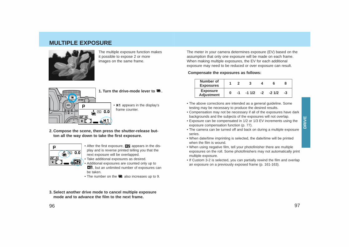
MULTIPLE EXPOSURE The meter in your camera determines exposure (EV) based on theassumption that only one exposure will be made on each frame.When making multiple exposures, the EV for each additionalexposure may need to be reduced or over exposure can result.
Compensate the exposures as follows:
Number ofExposuresExposure
Adjustment
1 2 3 4 6 8
0 -1 -1 1/2 -2 -2 1/2 -3
• The above corrections are intended as a general guideline. Sometesting may be necessary to produce the desired results.
• Compensation may not be necessary if all of the exposures have darkbackgrounds and the subjects of the exposures will not overlap.
• Exposure can be compensated in 1/2 or 1/3 EV increments using theexposure compensation function (p. 77).
• The camera can be turned off and back on during a multiple exposureseries.
• When date/time imprinting is selected, the date/time will be printedwhen the film is wound.
• When using negative film, tell your photofinisher there are multipleexposures on the roll. Some photofinishers may not automatically printmultiple exposure.
• If Custom 3-2 is selected, you can partially rewind the film and overlapan exposure on a previously exposed frame (p. 161-163).
1. Turn the drive-mode lever to .
The multiple exposure function makesit possible to expose 2 or moreimages on the same frame.
• appears in the display’sframe counter.
2. Compose the scene, then press the shutter-release but-ton all the way down to take the first exposure.
• After the first exposure, appears in the dis-play and is reverse printed telling you that thenext exposure will be overlapped.
• Take additional exposures as desired.• Additional exposures are counted only up to
, but an unlimited number of exposures canbe taken.
• The number on the also increases up to 9.
3. Select another drive mode to cancel multiple exposuremode and to advance the film to the next frame.
DR
IVE
9998
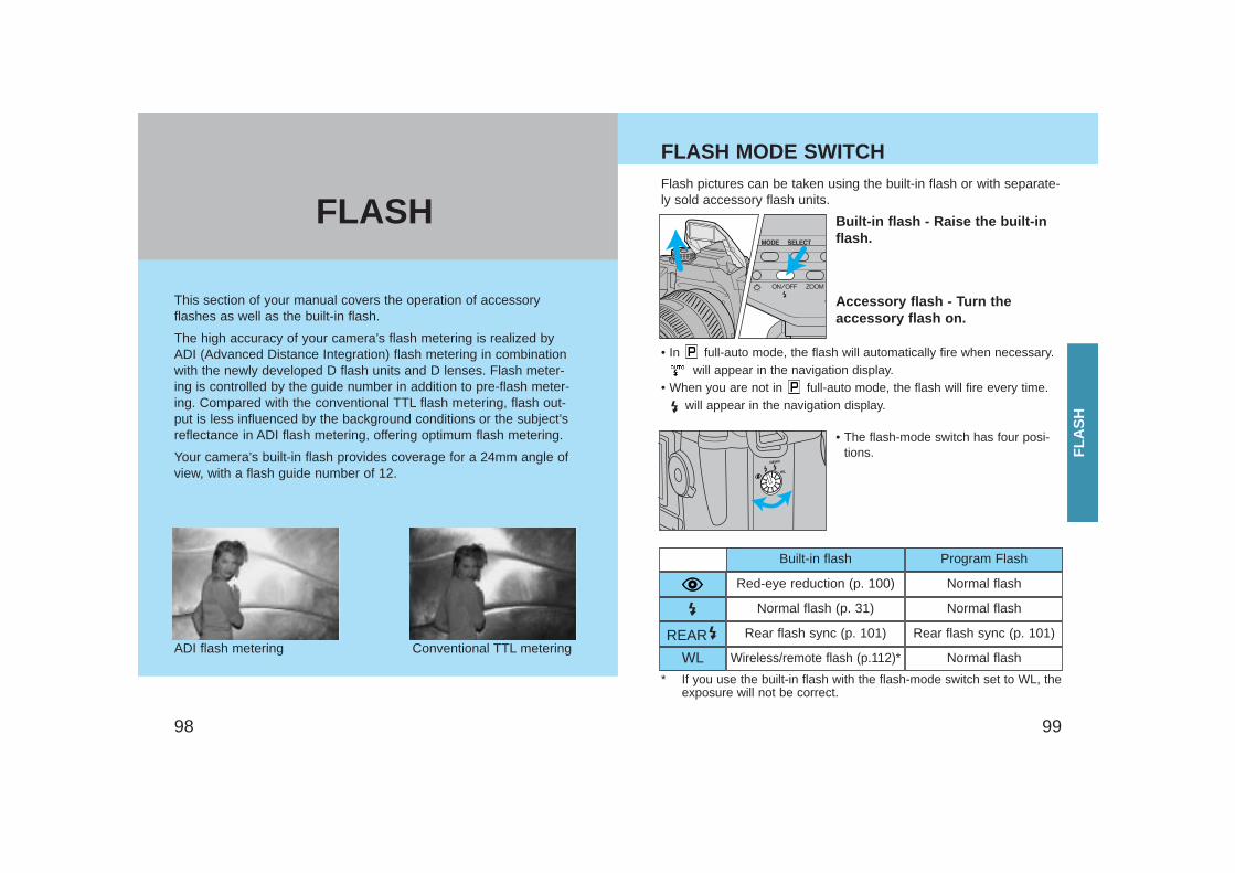
Red-eye reduction (p. 100) Normal flash
Normal flash (p. 31) Normal flash
REAR Rear flash sync (p. 101) Rear flash sync (p. 101)
WL Wireless/remote flash (p.112)* Normal flash
Built-in flash Program Flash
This section of your manual covers the operation of accessoryflashes as well as the built-in flash.
The high accuracy of your camera’s flash metering is realized byADI (Advanced Distance Integration) flash metering in combinationwith the newly developed D flash units and D lenses. Flash meter-ing is controlled by the guide number in addition to pre-flash meter-ing. Compared with the conventional TTL flash metering, flash out-put is less influenced by the background conditions or the subject’sreflectance in ADI flash metering, offering optimum flash metering.
Your camera’s built-in flash provides coverage for a 24mm angle ofview, with a flash guide number of 12.
ADI flash metering Conventional TTL metering
Built-in flash - Raise the built-inflash.
Accessory flash - Turn theaccessory flash on.
Flash pictures can be taken using the built-in flash or with separate-ly sold accessory flash units.
• The flash-mode switch has four posi-tions.
• In full-auto mode, the flash will automatically fire when necessary.will appear in the navigation display.
• When you are not in full-auto mode, the flash will fire every time.will appear in the navigation display.
* If you use the built-in flash with the flash-mode switch set to WL, theexposure will not be correct.
FLASH MODE SWITCH
FLA
SH
FLASH
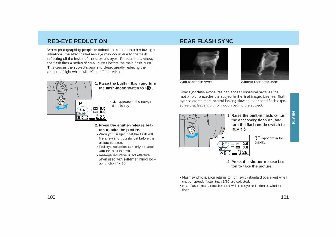
101100
RED-EYE REDUCTION REAR FLASH SYNC
With rear flash sync Without rear flash sync
Slow sync flash exposures can appear unnatural because themotion blur precedes the subject in the final image. Use rear flashsync to create more natural looking slow shutter speed flash expo-sures that leave a blur of motion behind the subject.
1. Raise the built-in flash, or turnthe accessory flash on, andturn the flash-mode switch toREAR .
• Flash synchronization returns to front sync (standard operation) whenshutter speeds faster than 1/60 are selected.
• Rear flash sync cannot be used with red-eye reduction or wirelessflash.
1. Raise the built-in flash and turnthe flash-mode switch to .
• appears in the naviga-tion display.
2. Press the shutter-release but-ton to take the picture.
• Warn your subject that the flash willfire a few short bursts just before thepicture is taken.
• Red-eye reduction can only be usedwith the built-in flash.
• Red-eye reduction is not effectivewhen used with self-timer, mirror lock-up function (p. 90).
When photographing people or animals at night or in other low-lightsituations, the effect called red-eye may occur due to the flashreflecting off the inside of the subject’s eyes. To reduce this effect,the flash fires a series of small bursts before the main flash burst.This causes the subject’s pupils to close, greatly reducing theamount of light which will reflect off the retina.
2. Press the shutter-release but-ton to take the picture.
• appears in thedisplay.
FLA
SH
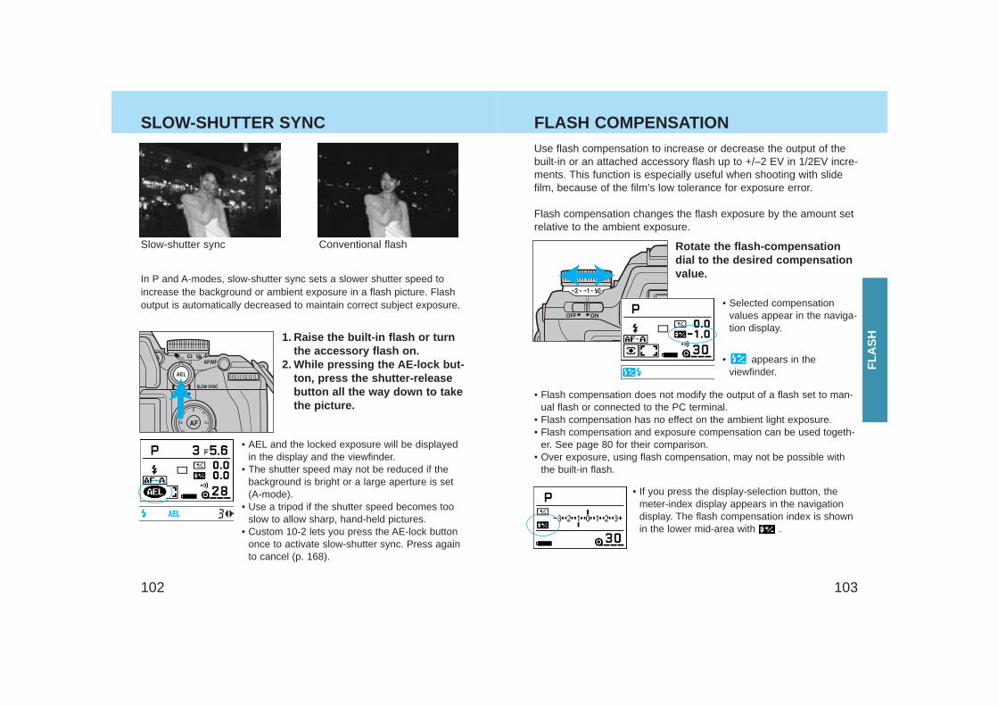
103102
Slow-shutter sync Conventional flash
In P and A-modes, slow-shutter sync sets a slower shutter speed toincrease the background or ambient exposure in a flash picture. Flashoutput is automatically decreased to maintain correct subject exposure.
1. Raise the built-in flash or turnthe accessory flash on.
2. While pressing the AE-lock but-ton, press the shutter-releasebutton all the way down to takethe picture.
• AEL and the locked exposure will be displayedin the display and the viewfinder.
• The shutter speed may not be reduced if thebackground is bright or a large aperture is set(A-mode).
• Use a tripod if the shutter speed becomes tooslow to allow sharp, hand-held pictures.
• Custom 10-2 lets you press the AE-lock buttononce to activate slow-shutter sync. Press againto cancel (p. 168).
Use flash compensation to increase or decrease the output of thebuilt-in or an attached accessory flash up to +/–2 EV in 1/2EV incre-ments. This function is especially useful when shooting with slidefilm, because of the film’s low tolerance for exposure error.
Flash compensation changes the flash exposure by the amount setrelative to the ambient exposure.
Rotate the flash-compensationdial to the desired compensationvalue.
• Selected compensation values appear in the naviga-tion display.
• appears in theviewfinder.
• Flash compensation does not modify the output of a flash set to man-ual flash or connected to the PC terminal.
• Flash compensation has no effect on the ambient light exposure.• Flash compensation and exposure compensation can be used togeth-
er. See page 80 for their comparison.• Over exposure, using flash compensation, may not be possible with
the built-in flash.
• If you press the display-selection button, themeter-index display appears in the navigationdisplay. The flash compensation index is shownin the lower mid-area with .
SLOW-SHUTTER SYNC FLASH COMPENSATION
FLA
SH
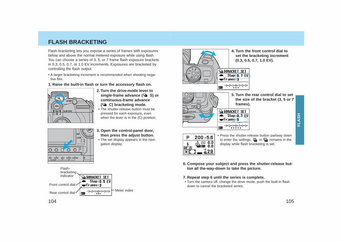
105104
FLASH BRACKETINGFlash bracketing lets you expose a series of frames with exposuresbelow and above the normal metered exposure while using flash.You can choose a series of 3, 5, or 7 frame flash exposure bracketsin 0.3, 0.5, 0.7, or 1.0 EV increments. Exposures are bracketed bycontrolling the flash output.
• A larger bracketing increment is recommended when shooting nega-tive film.
1. Raise the built-in flash or turn the accessory flash on.
2. Turn the drive-mode lever tosingle-frame advance ( S) orcontinuous-frame advance ( C) bracketing mode.
• The shutter-release button must bepressed for each exposure, evenwhen the lever is in the (C) position.
3. Open the control-panel door,then press the adjust button.
• The set display appears in the navi-gation display.
Flash-bracketingindicator
Front control dial
Meter indexRear control dial
4. Turn the front control dial toset the bracketing increment(0.3, 0.5, 0.7, 1.0 EV).
5. Turn the rear control dial to setthe size of the bracket (3, 5 or 7frames).
6. Compose your subject and press the shutter-release but-ton all the-way-down to take the picture.
7. Repeat step 6 until the series is complete.• Turn the camera off, change the drive mode, push the built-in flash
down to cancel the bracketed series.
• Press the shutter-release button partway downto enter the settings. or remains in thedisplay while flash bracketing is set.
FLA
SH
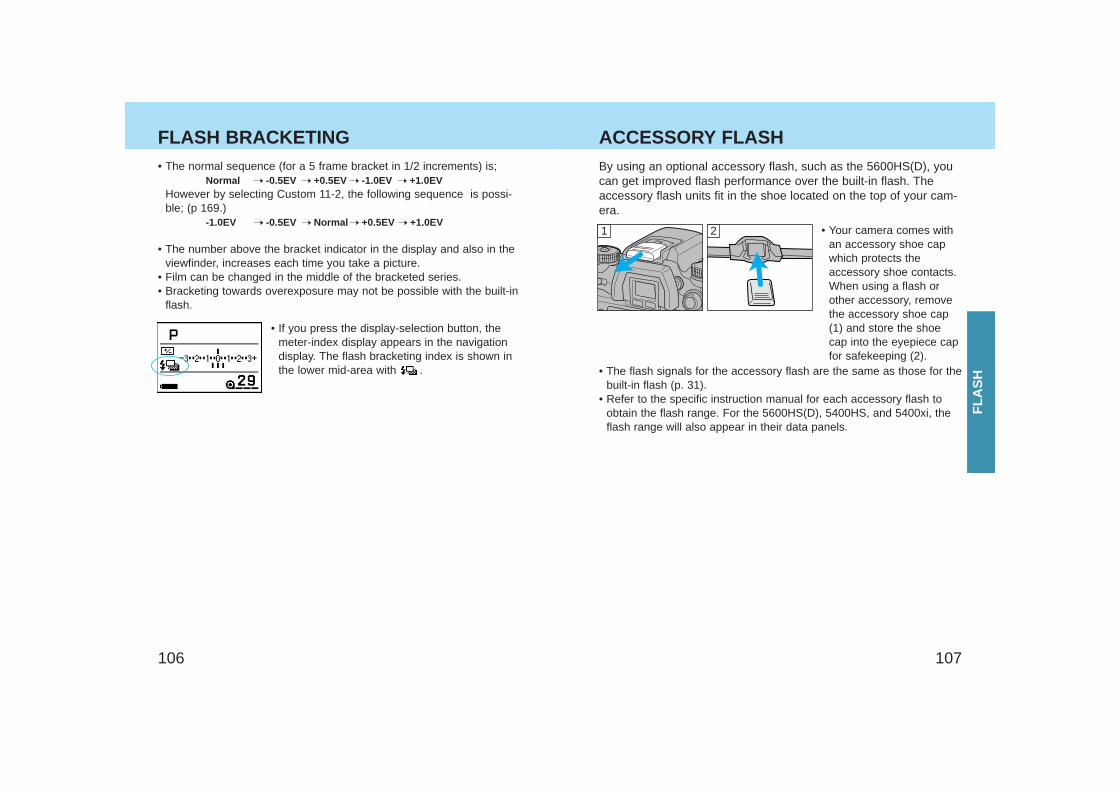
107106
• The normal sequence (for a 5 frame bracket in 1/2 increments) is;Normal ➝ -0.5EV ➝ +0.5EV ➝ -1.0EV ➝ +1.0EV
However by selecting Custom 11-2, the following sequence is possi-ble; (p 169.)
-1.0EV ➝ -0.5EV ➝ Normal ➝ +0.5EV ➝ +1.0EV
• The number above the bracket indicator in the display and also in theviewfinder, increases each time you take a picture.
• Film can be changed in the middle of the bracketed series.• Bracketing towards overexposure may not be possible with the built-in
flash.
• If you press the display-selection button, themeter-index display appears in the navigationdisplay. The flash bracketing index is shown inthe lower mid-area with .
• Your camera comes withan accessory shoe capwhich protects theaccessory shoe contacts.When using a flash orother accessory, removethe accessory shoe cap(1) and store the shoecap into the eyepiece capfor safekeeping (2).
21
By using an optional accessory flash, such as the 5600HS(D), youcan get improved flash performance over the built-in flash. Theaccessory flash units fit in the shoe located on the top of your cam-era.
• The flash signals for the accessory flash are the same as those for thebuilt-in flash (p. 31).
• Refer to the specific instruction manual for each accessory flash toobtain the flash range. For the 5600HS(D), 5400HS, and 5400xi, theflash range will also appear in their data panels.
FLASH BRACKETING ACCESSORY FLASH
FLA
SH
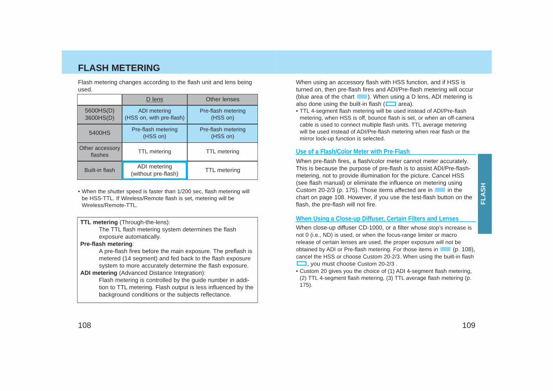
109108
Flash metering changes according to the flash unit and lens beingused.
5600HS(D)3600HS(D)
ADI metering(HSS on, with pre-flash)
Pre-flash metering(HSS on)
Built-in flashADI metering
(without pre-flash)TTL metering
5400HSPre-flash metering
(HSS on)Pre-flash metering
(HSS on)
Other accessoryflashes
TTL metering TTL metering
D lens Other lenses
• When the shutter speed is faster than 1/200 sec, flash metering willbe HSS-TTL. If Wireless/Remote flash is set, metering will beWireless/Remote-TTL.
When using an accessory flash with HSS function, and if HSS isturned on, then pre-flash fires and ADI/Pre-flash metering will occur(blue area of the chart ). When using a D lens, ADI metering isalso done using the built-in flash ( area).• TTL 4-segment flash metering will be used instead of ADI/Pre-flash
metering, when HSS is off, bounce flash is set, or when an off-cameracable is used to connect multiple flash units. TTL average meteringwill be used instead of ADI/Pre-flash metering when rear flash or themirror lock-up function is selected.
TTL metering (Through-the-lens):The TTL flash metering system determines the flashexposure automatically.
Pre-flash metering :A pre-flash fires before the main exposure. The preflash ismetered (14 segment) and fed back to the flash exposuresystem to more accurately determine the flash exposure.
ADI metering (Advanced Distance Integration):Flash metering is controlled by the guide number in addi-tion to TTL metering. Flash output is less influenced by thebackground conditions or the subjects reflectance.
When pre-flash fires, a flash/color meter cannot meter accurately.This is because the purpose of pre-flash is to assist ADI/Pre-flash-metering, not to provide illumination for the picture. Cancel HSS(see flash manual) or eliminate the influence on metering usingCustom 20-2/3 (p. 175). Those items affected are in in thechart on page 108. However, if you use the test-flash button on theflash, the pre-flash will not fire.
Use of a Flash/Color Meter with Pre-Flash
When Using a Close-up Diffuser, Certain Filters and Lenses When close-up diffuser CD-1000, or a filter whose stop’s increase isnot 0 (i.e., ND) is used, or when the focus-range limiter or macrorelease of certain lenses are used, the proper exposure will not beobtained by ADI or Pre-flash metering. For those items in (p. 108),cancel the HSS or choose Custom 20-2/3. When using the built-in flash
, you must choose Custom 20-2/3 .• Custom 20 gives you the choice of (1) ADI 4-segment flash metering,
(2) TTL 4-segment flash metering, (3) TTL average flash metering (p.175).
FLASH METERING
FLA
SH
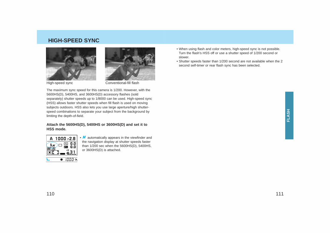
111110
HIGH-SPEED SYNC
The maximum sync speed for this camera is 1/200. However, with the5600HS(D), 5400HS, and 3600HS(D) accessory flashes (soldseparately) shutter speeds up to 1/8000 can be used. High-speed sync(HSS) allows faster shutter speeds when fill flash is used on movingsubjects outdoors. HSS also lets you use large aperture/high shutter-speed combinations to separate your subject from the background bylimiting the depth-of-field.
Attach the 5600HS(D), 5400HS or 3600HS(D) and set it toHSS mode.
High-speed sync Conventional-fill flash
• When using flash and color meters, high-speed sync is not possible.Turn the flash’s HSS off or use a shutter speed of 1/200 second orslower.
• Shutter speeds faster than 1/200 second are not available when the 2second self-timer or rear flash sync has been selected.
• automatically appears in the viewfinder andthe navigation display at shutter speeds fasterthan 1/200 sec when the 5600HS(D), 5400HS,or 3600HS(D) is attached.
FLA
SH
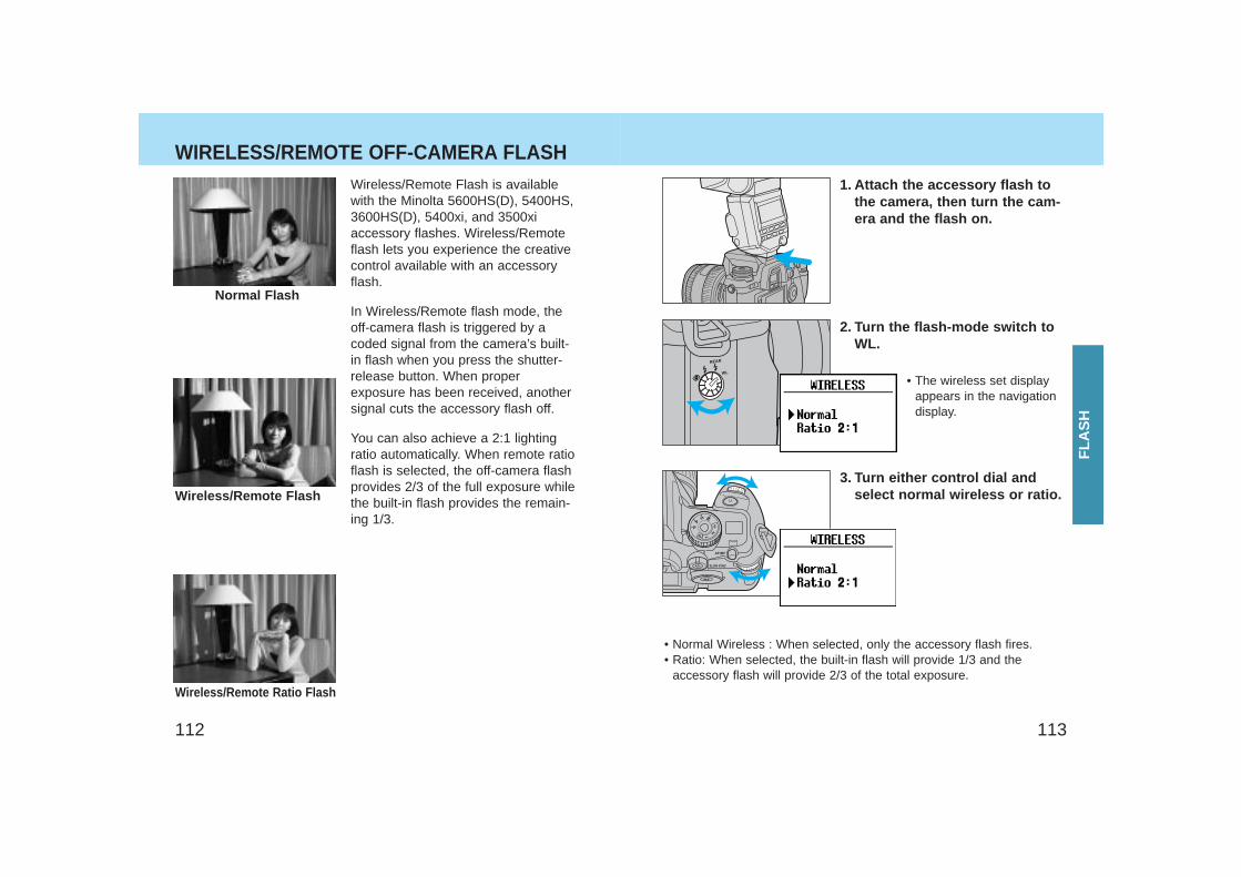
113112
Wireless/Remote Flash is availablewith the Minolta 5600HS(D), 5400HS,3600HS(D), 5400xi, and 3500xiaccessory flashes. Wireless/Remoteflash lets you experience the creativecontrol available with an accessoryflash.
In Wireless/Remote flash mode, theoff-camera flash is triggered by acoded signal from the camera’s built-in flash when you press the shutter-release button. When properexposure has been received, anothersignal cuts the accessory flash off.
You can also achieve a 2:1 lightingratio automatically. When remote ratioflash is selected, the off-camera flashprovides 2/3 of the full exposure whilethe built-in flash provides the remain-ing 1/3.
Normal Flash
Wireless/Remote Ratio Flash
Wireless/Remote Flash
1. Attach the accessory flash tothe camera, then turn the cam-era and the flash on.
2. Turn the flash-mode switch toWL.
• The wireless set displayappears in the navigationdisplay.
3. Turn either control dial andselect normal wireless or ratio.
• Normal Wireless : When selected, only the accessory flash fires.• Ratio: When selected, the built-in flash will provide 1/3 and the
accessory flash will provide 2/3 of the total exposure.
WIRELESS/REMOTE OFF-CAMERA FLASH
FLA
SH
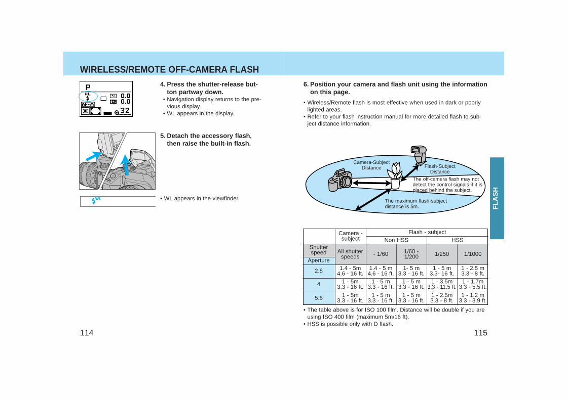
115114
WIRELESS/REMOTE OFF-CAMERA FLASH4. Press the shutter-release but-
ton partway down.• Navigation display returns to the pre-
vious display.• WL appears in the display.
5. Detach the accessory flash,then raise the built-in flash.
Flash-SubjectDistance
Camera-SubjectDistance
The off-camera flash may notdetect the control signals if it isplaced behind the subject.
The maximum flash-subjectdistance is 5m.
6. Position your camera and flash unit using the informationon this page.
• Wireless/Remote flash is most effective when used in dark or poorlylighted areas.
• Refer to your flash instruction manual for more detailed flash to sub-ject distance information.
Shutterspeed
Aperture
2.8
4
5.6
All shutterspeeds
1.4 - 5m4.6 - 16 ft.
1 - 5m3.3 - 16 ft.
1 - 5m3.3 - 16 ft.
- 1/60
1.4 - 5 m4.6 - 16 ft.
1 - 5 m3.3 - 16 ft.
1 - 5 m3.3 - 16 ft.
1/60 -1/200
1- 5 m3.3 - 16 ft.
1 - 5 m3.3 - 16 ft.
1 - 5 m3.3 - 16 ft.
1/250
1 - 5 m3.3- 16 ft.1 - 3.5m
3.3 - 11.5 ft.
1 - 2.5m3.3 - 8 ft.
1/1000
1 - 2.5 m3.3 - 8 ft.1 - 1.7m
3.3 - 5.5 ft.
1 - 1.2 m3.3 - 3.9 ft.
Non HSS HSS
• The table above is for ISO 100 film. Distance will be double if you areusing ISO 400 film (maximum 5m/16 ft).
• HSS is possible only with D flash.
Flash - subjectCamera -subject
• WL appears in the viewfinder.
FLA
SH
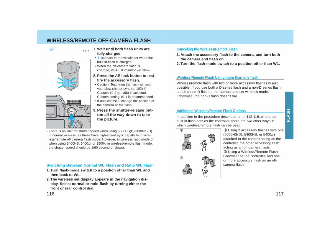
117116
WIRELESS/REMOTE OFF-CAMERA FLASH7. Wait until both flash units are
fully charged.• appears in the viewfinder when the
built-in flash is charged.• When the off-camera flash is
charged, its AF illuminator will blink.
8. Press the AE-lock button to testfire the accessory flash.
• Caution; Test firing the flash will acti-vate slow-shutter sync (p. 102) ifCustom 10-2 (p. 168) is selected.Custom setting 10-1 is recommended.
• If unsuccessful, change the position ofthe camera or the flash.
9. Press the shutter-release but-ton all the way down to takethe picture.
• There is no limit for shutter speed when using 5600HS(D)/3600HS(D)in normal wireless, as these have high-speed sync capability in wire-less/remote off camera flash mode. However, in wireless ratio mode orwhen using 5400HS, 5400xi, or 3500xi in wireless/remote flash mode,the shutter speed should be 1/60 second or slower.
Using 2 accessory flashes with one(5600HS(D), 5400HS, or 5400xi)attached to the camera acting as thecontroller, the other accessory flashacting as an off-camera flash.
Using a Wireless/Remote FlashController as the controller, and oneor more accessory flash as an off-camera flash.
1. Attach the accessory flash to the camera, and turn boththe camera and flash on.
2. Turn the flash-mode switch to a position other than WL.
Canceling the Wireless/Remote Flash
Additional Wireless/Remote Flash Options
Wireless/Remote Flash Using more than one flashWireless/remote flash with two or more accessory flashes is alsopossible. If you use both a D series flash and a non-D series flash,attach a non-D flash to the camera and set wireless mode.Otherwise, the non-D flash doesn’t fire.
In addition to the procedure described on p. 112-116, where thebuilt-in flash acts as the controller, there are two other ways inwhich wireless/remote flash can be used;
Switching Between Normal WL Flash and Ratio WL Flash1. Turn flash-mode switch to a position other than WL and
then back to WL.2. The wireless set display appears in the navigation dis-
play. Select normal or ratio-flash by turning either thefront or rear control dial.
FLA
SH
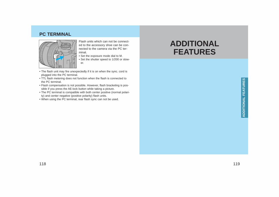
119118
PC TERMINALFlash units which can not be connect-ed to the accessory shoe can be con-nected to the camera via the PC ter-minal.• Set the exposure mode dial to M.• Set the shutter speed to 1/200 or slow-
er.
• The flash unit may fire unexpectedly if it is on when the sync. cord isplugged into the PC terminal.
• TTL flash metering does not function when the flash is connected tothe PC terminal.
• Flash compensation is not possible. However, flash bracketing is pos-sible if you press the AE-lock button while taking a picture.
• The PC terminal is compatible with both center positive (normal polari-ty) and center negative (positive polarity) flash units.
• When using the PC terminal, rear flash sync can not be used.
AD
DIT
ION
AL
FE
ATU
RE
S
ADDITIONALFEATURES
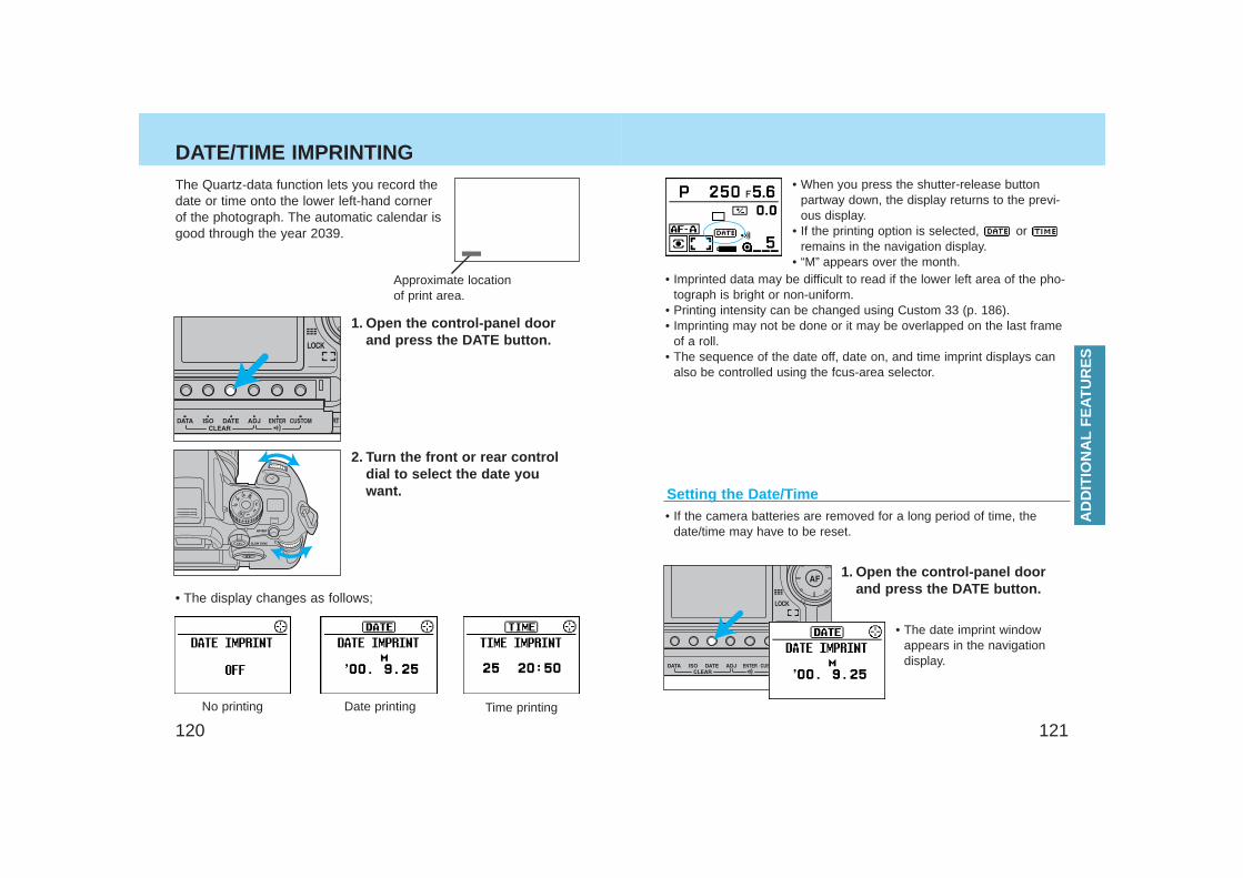
121120
DATE/TIME IMPRINTING
No printing Date printing Time printing
Setting the Date/Time
The Quartz-data function lets you record thedate or time onto the lower left-hand cornerof the photograph. The automatic calendar isgood through the year 2039.
Approximate locationof print area.
1. Open the control-panel doorand press the DATE button.
• The display changes as follows;
• When you press the shutter-release buttonpartway down, the display returns to the previ-ous display.
• If the printing option is selected, or remains in the navigation display.
• “M” appears over the month.
1. Open the control-panel doorand press the DATE button.
• The date imprint windowappears in the navigationdisplay.
• If the camera batteries are removed for a long period of time, thedate/time may have to be reset.
• Imprinted data may be difficult to read if the lower left area of the pho-tograph is bright or non-uniform.
• Printing intensity can be changed using Custom 33 (p. 186).• Imprinting may not be done or it may be overlapped on the last frame
of a roll.• The sequence of the date off, date on, and time imprint displays can
also be controlled using the fcus-area selector.
2. Turn the front or rear controldial to select the date youwant.
AD
DIT
ION
AL
FE
ATU
RE
S
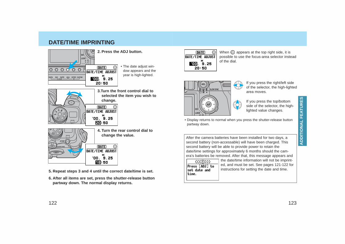
123122
DATE/TIME IMPRINTING
6. After all items are set, press the shutter-release buttonpartway down. The normal display returns.
4. Turn the rear control dial tochange the value.
3.Turn the front control dial toselected the item you wish tochange.
When appears at the top right side, it ispossible to use the focus-area selector insteadof the dial.
If you press the right/left sideof the selector, the high-lightedarea moves.
If you press the top/bottomside of the selector, the high-lighted value changes.
• Display returns to normal when you press the shutter-release buttonpartway down.
After the camera batteries have been installed for two days, asecond battery (non-accessable) will have been charged. Thissecond battery will be able to provide power to retain thedate/time settings for approximately 6 months should the cam-era’s batteries be removed. After that, this message appears and
the date/time information will not be imprint-ed, and must be set. See pages 121-122 forinstructions for setting the date and time.
2. Press the ADJ button.
• The date adjust win-dow appears and theyear is high-lighted.
5. Repeat steps 3 and 4 until the correct date/time is set.
AD
DIT
ION
AL
FE
ATU
RE
S
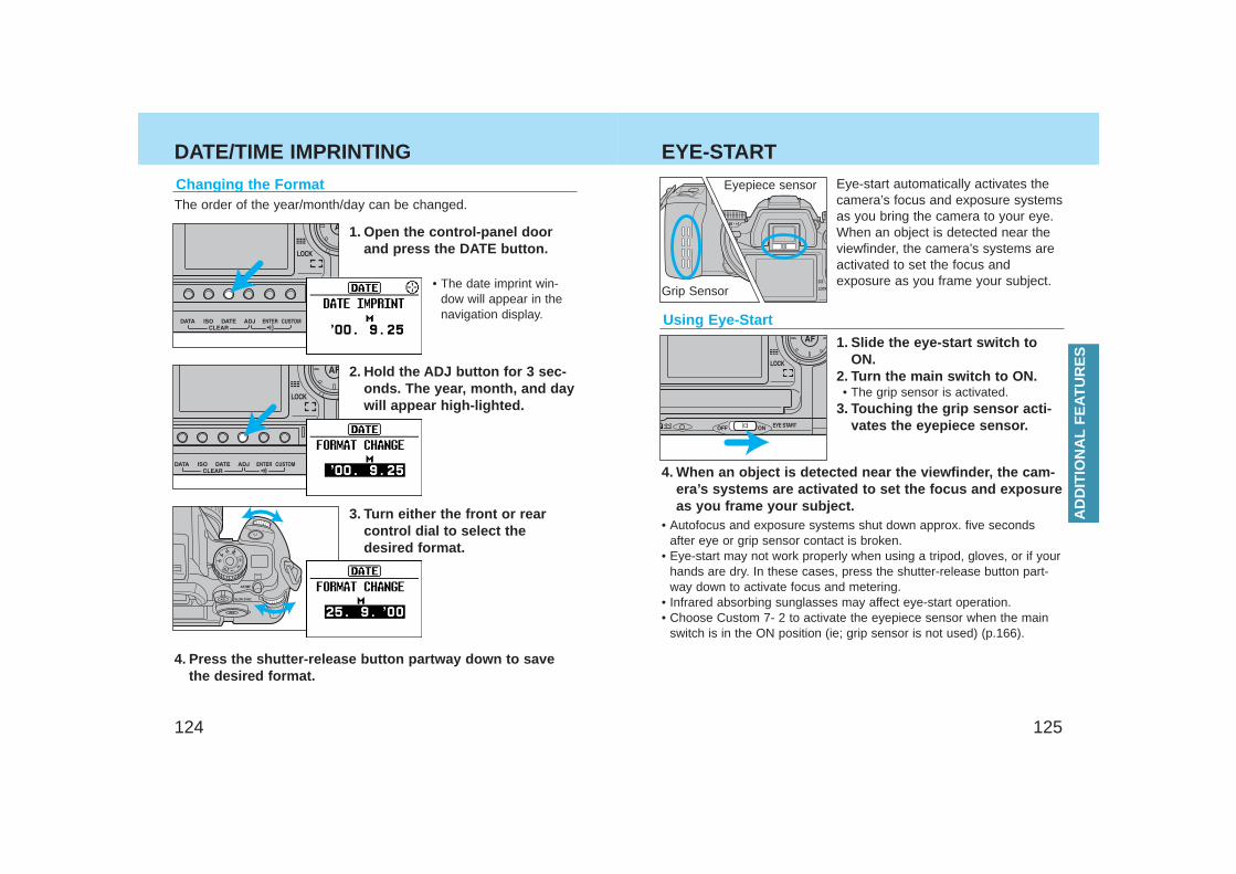
125124
DATE/TIME IMPRINTING
Using Eye-Start
1. Slide the eye-start switch toON.
2. Turn the main switch to ON.• The grip sensor is activated.
3. Touching the grip sensor acti-vates the eyepiece sensor.
• Autofocus and exposure systems shut down approx. five secondsafter eye or grip sensor contact is broken.
• Eye-start may not work properly when using a tripod, gloves, or if yourhands are dry. In these cases, press the shutter-release button part-way down to activate focus and metering.
• Infrared absorbing sunglasses may affect eye-start operation.• Choose Custom 7- 2 to activate the eyepiece sensor when the main
switch is in the ON position (ie; grip sensor is not used) (p.166).
Eye-start automatically activates thecamera’s focus and exposure systemsas you bring the camera to your eye.When an object is detected near theviewfinder, the camera’s systems areactivated to set the focus andexposure as you frame your subject.
4. When an object is detected near the viewfinder, the cam-era’s systems are activated to set the focus and exposureas you frame your subject.
Changing the Format The order of the year/month/day can be changed.
1. Open the control-panel doorand press the DATE button.
3. Turn either the front or rearcontrol dial to select thedesired format.
2. Hold the ADJ button for 3 sec-onds. The year, month, and daywill appear high-lighted.
4. Press the shutter-release button partway down to savethe desired format.
• The date imprint win-dow will appear in thenavigation display.
EYE-START
Grip Sensor
Eyepiece sensor
AD
DIT
ION
AL
FE
ATU
RE
S
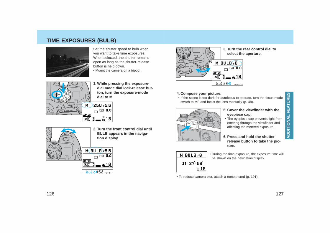
127126
TIME EXPOSURES (BULB)
AD
DIT
ION
AL
FE
ATU
RE
S
• To reduce camera blur, attach a remote cord (p. 191).
5. Cover the viewfinder with theeyepiece cap.
• The eyepiece cap prevents light fromentering through the viewfinder andaffecting the metered exposure.
6. Press and hold the shutter-release button to take the pic-ture.
• During the time exposure, the exposure time willbe shown on the navigation display.
4. Compose your picture.• If the scene is too dark for autofocus to operate, turn the focus-mode
switch to MF and focus the lens manually (p. 48).
3. Turn the rear control dial toselect the aperture.
Set the shutter speed to bulb whenyou want to take time exposures.When selected, the shutter remainsopen as long as the shutter-releasebutton is held down.• Mount the camera on a tripod.
1. While pressing the exposure-dial mode dial lock-release but-ton, turn the exposure-modedial to M.
2. Turn the front control dial untilBULB appears in the naviga-tion display.
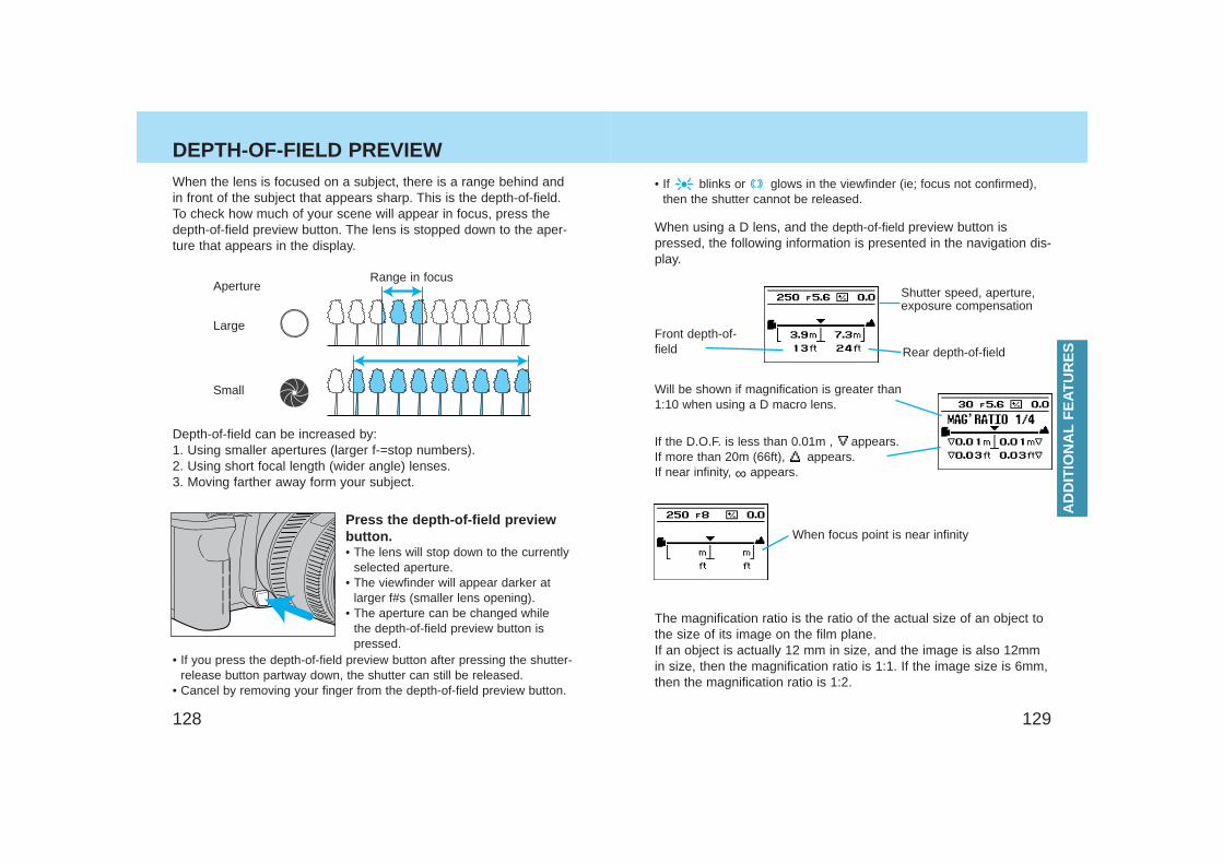
129128
When focus point is near infinity
When using a D lens, and the depth-of-field preview button ispressed, the following information is presented in the navigation dis-play.
Shutter speed, aperture,exposure compensation
Will be shown if magnification is greater than1:10 when using a D macro lens.
If the D.O.F. is less than 0.01m , appears. If more than 20m (66ft), appears.If near infinity, ∞ appears.
Front depth-of-field Rear depth-of-field
• If blinks or glows in the viewfinder (ie; focus not confirmed),then the shutter cannot be released.
The magnification ratio is the ratio of the actual size of an object tothe size of its image on the film plane. If an object is actually 12 mm in size, and the image is also 12mmin size, then the magnification ratio is 1:1. If the image size is 6mm,then the magnification ratio is 1:2.
When the lens is focused on a subject, there is a range behind andin front of the subject that appears sharp. This is the depth-of-field.To check how much of your scene will appear in focus, press thedepth-of-field preview button. The lens is stopped down to the aper-ture that appears in the display.
Depth-of-field can be increased by:1. Using smaller apertures (larger f-=stop numbers).2. Using short focal length (wider angle) lenses.3. Moving farther away form your subject.
Range in focusAperture
Press the depth-of-field previewbutton.• The lens will stop down to the currently
selected aperture. • The viewfinder will appear darker at
larger f#s (smaller lens opening).• The aperture can be changed while
the depth-of-field preview button ispressed.
• If you press the depth-of-field preview button after pressing the shutter-release button partway down, the shutter can still be released.
• Cancel by removing your finger from the depth-of-field preview button.
Large
Small
DEPTH-OF-FIELD PREVIEW
AD
DIT
ION
AL
FE
ATU
RE
S
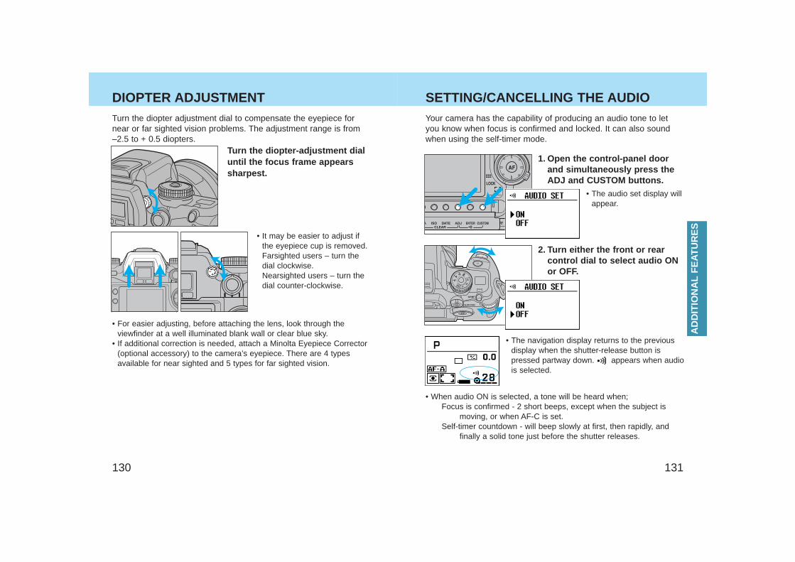
131130
DIOPTER ADJUSTMENT
• When audio ON is selected, a tone will be heard when;Focus is confirmed - 2 short beeps, except when the subject is
moving, or when AF-C is set.Self-timer countdown - will beep slowly at first, then rapidly, and
finally a solid tone just before the shutter releases.
1. Open the control-panel doorand simultaneously press theADJ and CUSTOM buttons.
2. Turn either the front or rearcontrol dial to select audio ONor OFF.
• The audio set display willappear.
• The navigation display returns to the previousdisplay when the shutter-release button ispressed partway down. appears when audiois selected.
Your camera has the capability of producing an audio tone to letyou know when focus is confirmed and locked. It can also soundwhen using the self-timer mode.
SETTING/CANCELLING THE AUDIO
AD
DIT
ION
AL
FE
ATU
RE
S
• It may be easier to adjust ifthe eyepiece cup is removed.Farsighted users – turn thedial clockwise.Nearsighted users – turn thedial counter-clockwise.
Turn the diopter-adjustment dialuntil the focus frame appearssharpest.
• For easier adjusting, before attaching the lens, look through theviewfinder at a well illuminated blank wall or clear blue sky.
• If additional correction is needed, attach a Minolta Eyepiece Corrector(optional accessory) to the camera’s eyepiece. There are 4 typesavailable for near sighted and 5 types for far sighted vision.
Turn the diopter adjustment dial to compensate the eyepiece fornear or far sighted vision problems. The adjustment range is from–2.5 to + 0.5 diopters.
133132
The following settings will be stored in your camera by using thememory function.• Exposure mode (P, A, S, M)• Shutter speed in S mode, aperture in A mode, shutter speed and
aperture in M mode.• Focus mode (AF-A, AF-C, AF-S, Manual focus)• Focus area (wide focus area, local focus area)• Metering mode (14-segment honeycomb-pattern, spot, center-weight-
ed average)• Exposure compensation value• Flash compensation value• Film drive mode (single-frame, continuous, bracketing, self-timer, mul-
tiple exposures) • The adjust button settings for the drive mode (continuous and bracket-
ing). Increment and size will be stored independently for the exposurebracketing and flash bracketing.
• Flash mode with the built-in flash (normal, red-eye reduction, rearflash sync, wireless/remote flash). However, whether the built-in flashwas on or off will not be stored.
• AF/Release priority (Custom 1 setting)• Tasking on focus mode dial, AF-A position (Custom 22 setting)
When using the memory function, you cannot choose to have onlypart of the above settings stored. All of them will be stored automat-ically. No other settings will be stored in memory. eg: date imprint-ing, display contrast, custom function settings (other that #1 or#22), etc.
The memory function allows you to store a variety of camera set-tings as a group and recall them at any time. Three diferent set ofcamera function settings can be stored.
• Each of the following can be stored in memory. See the appropri-ate section for details.- Exposure mode- Focus mode/Focus area- Metering mode- Exposure compensation/Flash compensation- Drive mode- Flash mode- AF priority/Release priotity
MEMORY
ME
MO
RY
MEMORY
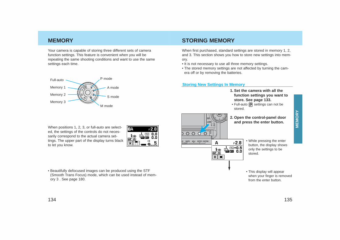
135134
MEMORY
Storing New Settings In Memory
When first purchased, standard settings are stored in memory 1, 2,and 3. This section shows you how to store new settings into mem-ory.• It is not necessary to use all three memory settings.• The stored memory settings are not affected by turning the cam-
era off or by removing the batteries.
1. Set the camera with all thefunction settings you want tostore. See page 133.
• Full-auto settings can not bestored.
2. Open the control-panel doorand press the enter button.
• While pressing the enterbutton, the display showsonly the settings to bestored.
• This display will appearwhen your finger is removedfrom the enter button.
Full-auto
Your camera is capable of storing three different sets of camerafunction settings. This feature is convenient when you will berepeating the same shooting conditions and want to use the samesettings each time.
Memory 1
Memory 2
Memory 3
• Beautifully defocused images can be produced using the STF(Smooth Trans Focus) mode, which can be used instead of mem-ory 3 . See page 180.
When positions 1, 2, 3, or full-auto are select-ed, the settings of the controls do not neces-sarily correspond to the actual camera set-tings. The upper part of the display turns blackto let you know.
P mode
A mode
S mode
M mode
STORING MEMORY
ME
MO
RY
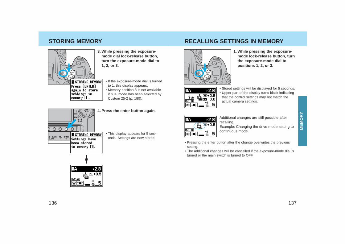
137136
1. While pressing the exposure-mode lock-release button, turnthe exposure-mode dial topositions 1, 2, or 3.
• Stored settings will be displayed for 5 seconds.• Upper part of the display turns black indicating
that the control settings may not match theactual camera settings.
Additional changes are still possible afterrecalling.Example: Changing the drive mode setting tocontinuous mode.
• Pressing the enter button after the change overwrites the previoussetting.
• The additional changes will be cancelled if the exposure-mode dial isturned or the main switch is turned to OFF.
3. While pressing the exposure-mode dial lock-release button,turn the exposure-mode dial to1, 2, or 3.
• If the exposure-mode dial is turnedto 1, this display appears.
• Memory position 3 is not availableif STF mode has been selected byCustom 25-2 (p. 180).
4. Press the enter button again.
• This display appears for 5 sec-onds. Settings are now stored.
STORING MEMORY RECALLING SETTINGS IN MEMORY
ME
MO
RY
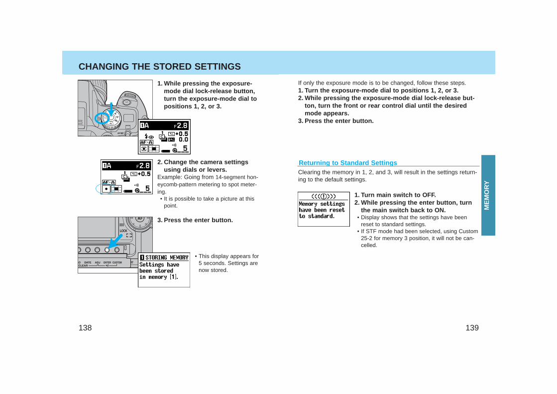
139138
Returning to Standard Settings
If only the exposure mode is to be changed, follow these steps.1. Turn the exposure-mode dial to positions 1, 2, or 3.2. While pressing the exposure-mode dial lock-release but-
ton, turn the front or rear control dial until the desiredmode appears.
3. Press the enter button.
Clearing the memory in 1, 2, and 3, will result in the settings return-ing to the default settings.
1. Turn main switch to OFF.2. While pressing the enter button, turn
the main switch back to ON.• Display shows that the settings have been
reset to standard settings.• If STF mode had been selected, using Custom
25-2 for memory 3 position, it will not be can-celled.
1. While pressing the exposure-mode dial lock-release button,turn the exposure-mode dial topositions 1, 2, or 3.
2. Change the camera settingsusing dials or levers.
Example: Going from 14-segment hon-eycomb-pattern metering to spot meter-ing.• It is possible to take a picture at this
point.
• This display appears for5 seconds. Settings arenow stored.
3. Press the enter button.
CHANGING THE STORED SETTINGS
ME
MO
RY
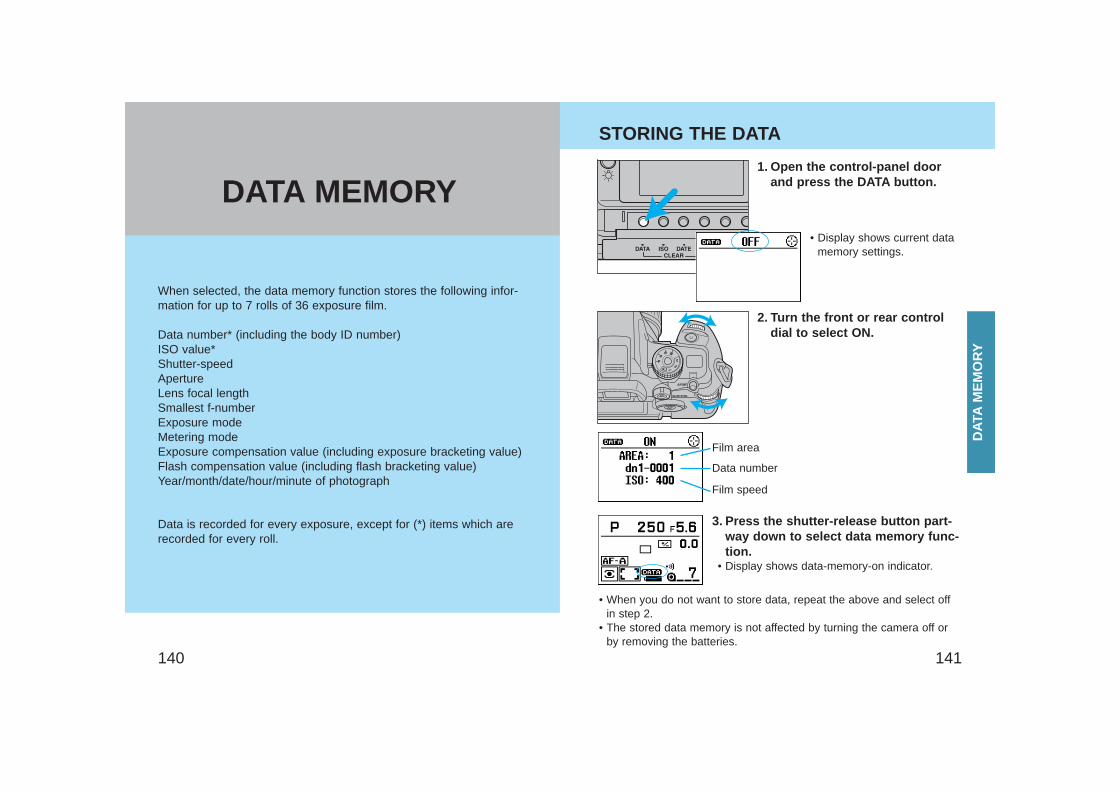
141140
When selected, the data memory function stores the following infor-mation for up to 7 rolls of 36 exposure film.
Data number* (including the body ID number) ISO value*Shutter-speedApertureLens focal lengthSmallest f-numberExposure modeMetering modeExposure compensation value (including exposure bracketing value)Flash compensation value (including flash bracketing value)Year/month/date/hour/minute of photograph
Data is recorded for every exposure, except for (*) items which arerecorded for every roll.
1. Open the control-panel doorand press the DATA button.
• Display shows current datamemory settings.
STORING THE DATA
2. Turn the front or rear controldial to select ON.
Film area
Data number
Film speed
3. Press the shutter-release button part-way down to select data memory func-tion.
• Display shows data-memory-on indicator.
• When you do not want to store data, repeat the above and select offin step 2.
• The stored data memory is not affected by turning the camera off orby removing the batteries.
DAT
AM
EM
OR
Y
DATA MEMORY
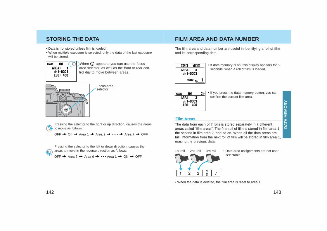
143142
STORING THE DATA
Film Areas
• Data is not stored unless film is loaded.• When multiple exposure is selected, only the data of the last exposure
will be stored.
When appears, you can use the focus-area selector, as well as the front or rear con-trol dial to move between areas.
FILM AREA AND DATA NUMBER
The film area and data number are useful in identifying a roll of filmand its corresponding data.
• If you press the data-memory button, you canconfirm the current film area.
The data from each of 7 rolls is stored separately in 7 differentareas called “film areas”. The first roll of film is stored in film area 1,the second in film area 2, and so on. When all the data areas arefull, information from the next roll of film will be stored in film area 1,erasing the previous data.
• When the data is deleted, the film area is reset to area 1.
1st roll 2nd roll 3rd roll
• If data memory is on, this display appears for 5seconds, when a roll of film is loaded.
• Data area assignments are not userselectable.
Pressing the selector to the left or down direction, causes theareas to move in the reverse direction as follows:
OFF Area 7 Area 6 • • • Area 1 ON OFF
Pressing the selector to the right or up direction, causes the areasto move as follows:
OFF On Area 1 Area 2 • • • Area 7 OFF
Focus-areaselector
DAT
AM
EM
OR
Y
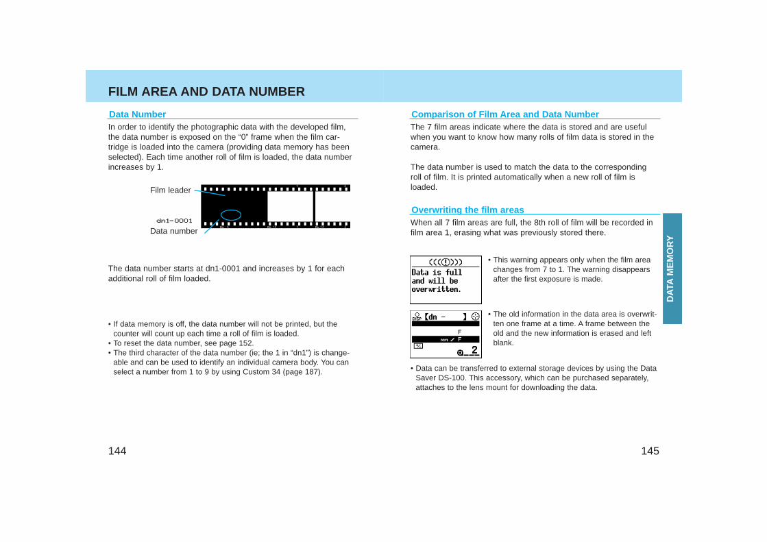
145144
FILM AREA AND DATA NUMBER
Data NumberIn order to identify the photographic data with the developed film,the data number is exposed on the “0” frame when the film car-tridge is loaded into the camera (providing data memory has beenselected). Each time another roll of film is loaded, the data numberincreases by 1.
The data number starts at dn1-0001 and increases by 1 for eachadditional roll of film loaded.
• If data memory is off, the data number will not be printed, but thecounter will count up each time a roll of film is loaded.
• To reset the data number, see page 152.• The third character of the data number (ie; the 1 in “dn1”) is change-
able and can be used to identify an individual camera body. You canselect a number from 1 to 9 by using Custom 34 (page 187).
The 7 film areas indicate where the data is stored and are usefulwhen you want to know how many rolls of film data is stored in thecamera.
The data number is used to match the data to the correspondingroll of film. It is printed automatically when a new roll of film isloaded.
Comparison of Film Area and Data Number
When all 7 film areas are full, the 8th roll of film will be recorded infilm area 1, erasing what was previously stored there.
Overwriting the film areas
• This warning appears only when the film areachanges from 7 to 1. The warning disappearsafter the first exposure is made.
• The old information in the data area is overwrit-ten one frame at a time. A frame between theold and the new information is erased and leftblank.
• Data can be transferred to external storage devices by using the DataSaver DS-100. This accessory, which can be purchased separately,attaches to the lens mount for downloading the data.
Film leader
Data number
DAT
AM
EM
OR
Y
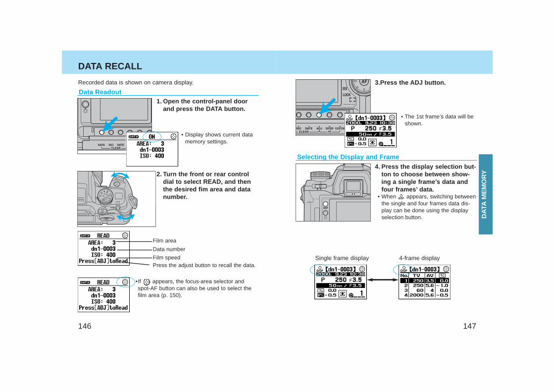
147146
DATA RECALL
1. Open the control-panel doorand press the DATA button.
• Display shows current datamemory settings.
2. Turn the front or rear controldial to select READ, and thenthe desired fim area and datanumber.
Film area
Data number
Film speedPress the adjust button to recall the data.
•If appears, the focus-area selector andspot-AF button can also be used to select thefilm area (p. 150).
3.Press the ADJ button.
• The 1st frame’s data will beshown.
Selecting the Display and Frame4. Press the display selection but-
ton to choose between show-ing a single frame’s data andfour frames’ data.
• When appears, switching betweenthe single and four frames data dis-play can be done using the displayselection button.
Single frame display 4-frame display
Recorded data is shown on camera display.
Data Readout
DAT
AM
EM
OR
Y
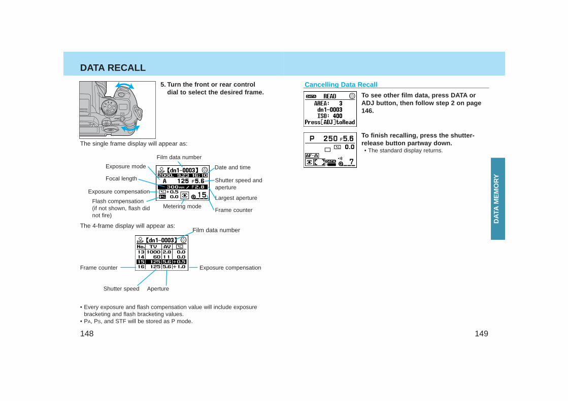
148 149
DATA RECALL
5. Turn the front or rear controldial to select the desired frame.
Exposure mode
Focal length
Exposure compensation
Flash compensation(if not shown, flash didnot fire)
Frame counter
Shutter speed Aperture
Exposure compensation
Metering mode
Largest aperture
Frame counter
Date and time
Shutter speed andaperture
Film data number
To see other film data, press DATA orADJ button, then follow step 2 on page146.
To finish recalling, press the shutter-release button partway down.• The standard display returns.
Cancelling Data Recall
The 4-frame display will appear as:
The single frame display will appear as:
Film data number
• Every exposure and flash compensation value will include exposurebracketing and flash bracketing values.
• PA, PS, and STF will be stored as P mode.
DAT
AM
EM
OR
Y
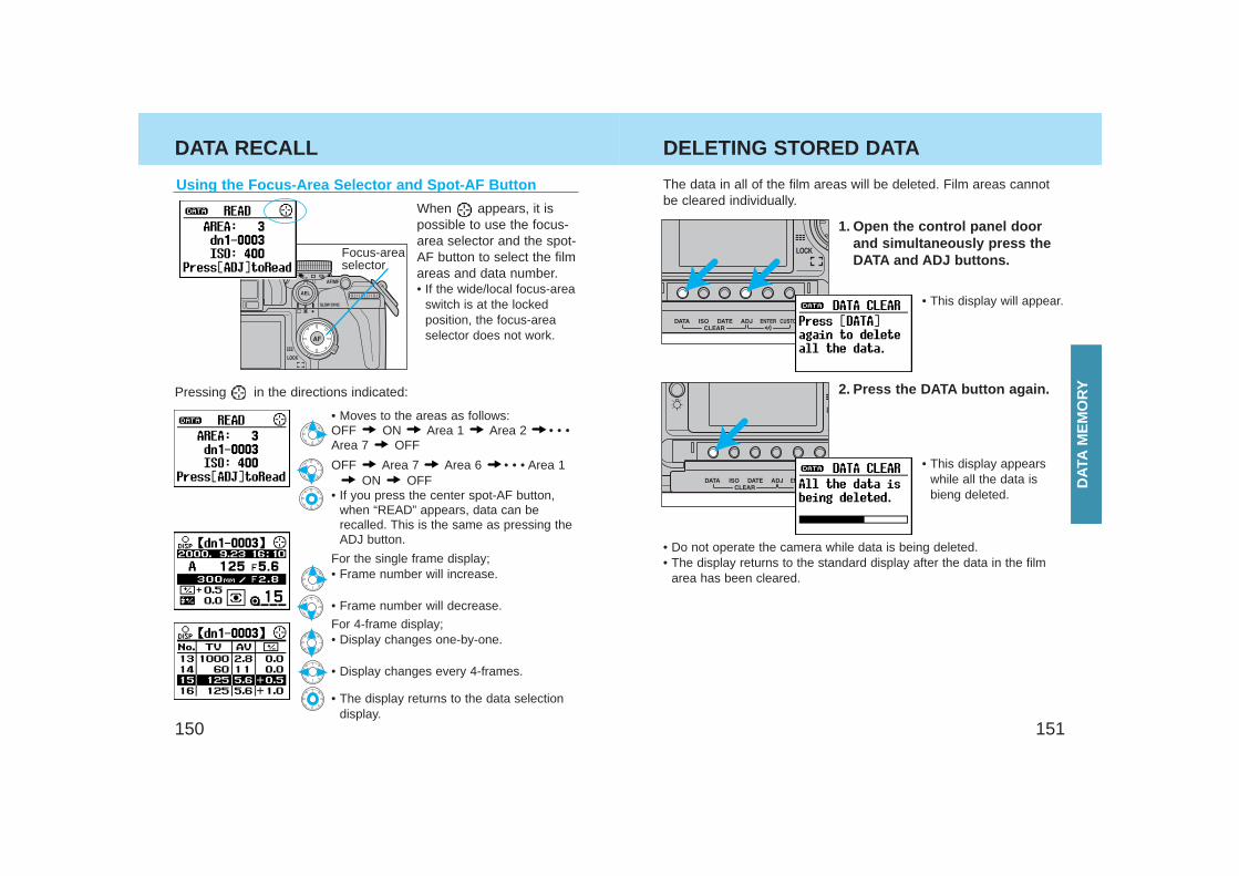
151150
DATA RECALL
Using the Focus-Area Selector and Spot-AF Button
When appears, it ispossible to use the focus-area selector and the spot-AF button to select the filmareas and data number.• If the wide/local focus-area
switch is at the lockedposition, the focus-areaselector does not work.
Pressing in the directions indicated:
• Moves to the areas as follows:OFF ON Area 1 Area 2 • • •Area 7 OFF
OFF Area 7 Area 6 • • • Area 1ON OFF
• If you press the center spot-AF button,when “READ” appears, data can berecalled. This is the same as pressing theADJ button.
For the single frame display;• Frame number will increase.
• Frame number will decrease.
For 4-frame display;• Display changes one-by-one.
• Display changes every 4-frames.
• The display returns to the data selectiondisplay.
DELETING STORED DATA
1. Open the control panel doorand simultaneously press theDATA and ADJ buttons.
The data in all of the film areas will be deleted. Film areas cannotbe cleared individually.
• This display will appear.
2. Press the DATA button again.
• This display appearswhile all the data isbieng deleted.
• Do not operate the camera while data is being deleted.• The display returns to the standard display after the data in the film
area has been cleared.
Focus-areaselector
DAT
AM
EM
OR
Y
153152
DELETING STORED DATA
Film Area and Data Number ResetEverytime film is loaded, both the film area and data numberincreases by 1. When you first buy your camera, both are set to 1.Film area reset:When the data is deleted (p. 151), the film area returns to 1.• The data number is not reset when the film area is reset.
Custom functions let you tailor the camera to your shooting style orpreferences. There are 35 custom functions. These are explainedon pages 158-187.
Data number reset:1. Turn the main switch to OFF.2. While pressing the DATA button, turn
the main switch from OFF to ON.• The last four digits are reset to 0001. • Data number cannot be reset is the film is in
the camera.• Resetting the data number does not delete the
data or reset the film area.
CU
STO
M F
UN
CT
ION
S
CUSTOM FUNCTIONS
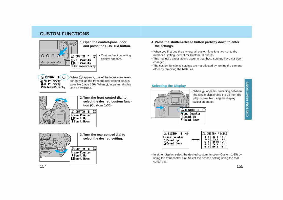
155154
CUSTOM FUNCTIONS
1. Open the control-panel doorand press the CUSTOM button.
• Custom function settingdisplay appears.
•When appears, use of the focus area selec-tor as well as the front and rear control dials ispossible (page 156). When appears, displaycan be switched.
2. Turn the front control dial toselect the desired custom func-tion (Custom 1-35).
3. Turn the rear control dial toselect the desired setting.
4. Press the shutter-release button partway down to enterthe settings.
• When you first buy the camera, all custom functions are set to thenumber 1 setting, except for Custom 33 and 35.
• This manual’s explanations assume that these settings have not beenchanged.
• The custom functions’ settings are not affected by turning the cameraoff or by removing the batteries.
Selecting the Display
• In either display, select the desired custom function (Custom 1-35) byusing the front control dial. Select the desired setting using the rearcontol dial.
• When appears, switching betweenthe single display and the 15 item dis-play is possible using the displayselection button.
CU
STO
M F
UN
CT
ION
S
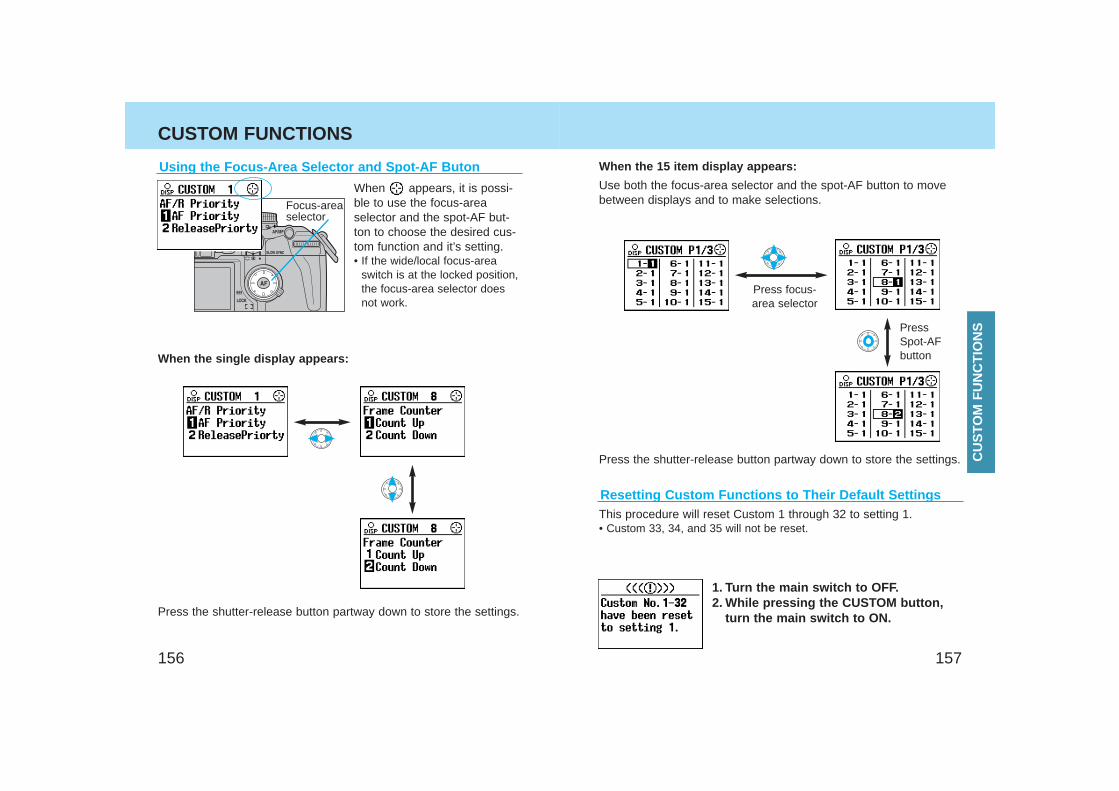
157156
Using the Focus-Area Selector and Spot-AF Buton
CUSTOM FUNCTIONS
When appears, it is possi-ble to use the focus-areaselector and the spot-AF but-ton to choose the desired cus-tom function and it’s setting.• If the wide/local focus-area
switch is at the locked position,the focus-area selector doesnot work.
When the single display appears:
Press the shutter-release button partway down to store the settings.
When the 15 item display appears:
Press focus-area selector
PressSpot-AFbutton
Press the shutter-release button partway down to store the settings.
Resetting Custom Functions to Their Default Settings
Use both the focus-area selector and the spot-AF button to movebetween displays and to make selections.
This procedure will reset Custom 1 through 32 to setting 1.• Custom 33, 34, and 35 will not be reset.
1. Turn the main switch to OFF.2. While pressing the CUSTOM button,
turn the main switch to ON.
Focus-areaselector
CU
STO
M F
UN
CT
ION
S
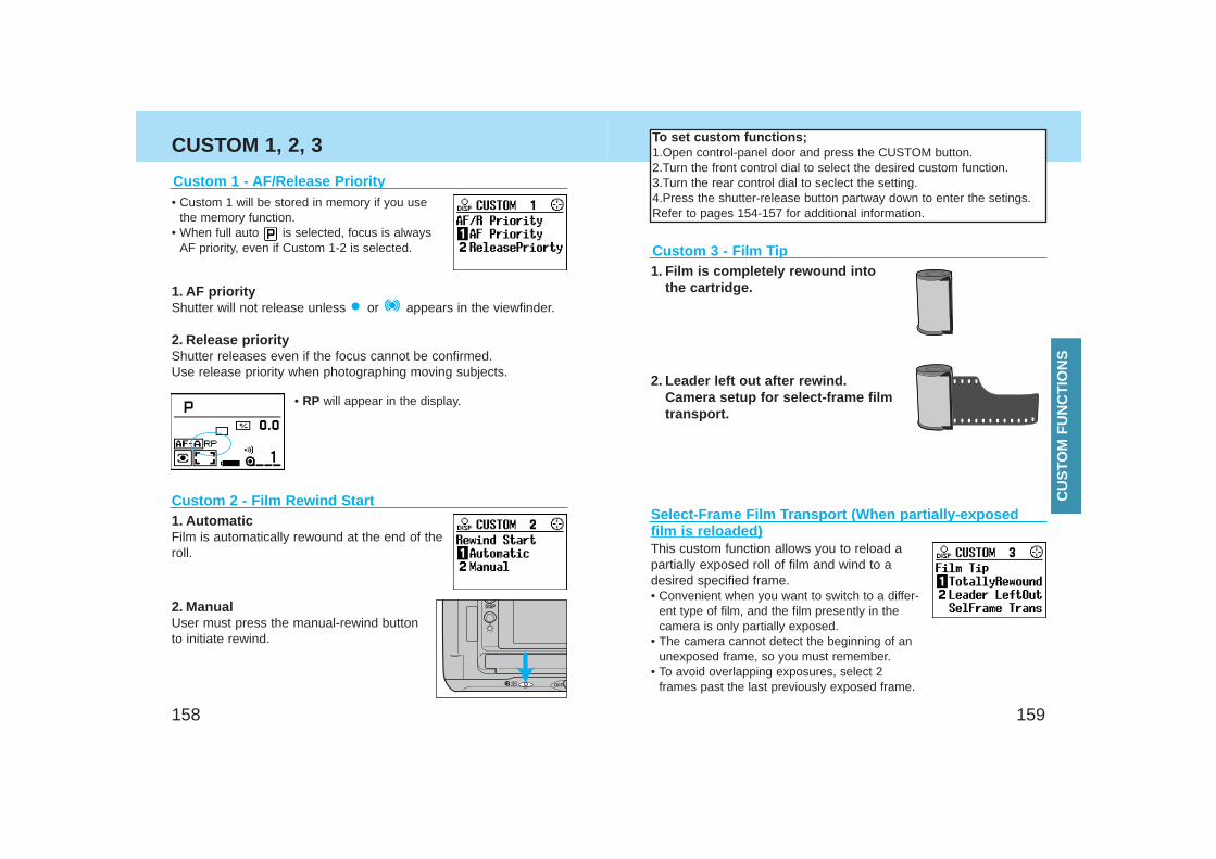
159158
CUSTOM 1, 2, 3
Custom 1 - AF/Release Priority• Custom 1 will be stored in memory if you use
the memory function.• When full auto is selected, focus is always
AF priority, even if Custom 1-2 is selected.
1. AF priorityShutter will not release unless or appears in the viewfinder.
2. Release priorityShutter releases even if the focus cannot be confirmed.Use release priority when photographing moving subjects.
• RP will appear in the display.
Custom 2 - Film Rewind Start1. AutomaticFilm is automatically rewound at the end of theroll.
2. ManualUser must press the manual-rewind buttonto initiate rewind.
1. Film is completely rewound intothe cartridge.
2. Leader left out after rewind.Camera setup for select-frame filmtransport.
Custom 3 - Film Tip
Select-Frame Film Transport (When partially-exposedfilm is reloaded)This custom function allows you to reload apartially exposed roll of film and wind to adesired specified frame.• Convenient when you want to switch to a differ-
ent type of film, and the film presently in thecamera is only partially exposed.
• The camera cannot detect the beginning of anunexposed frame, so you must remember.
• To avoid overlapping exposures, select 2frames past the last previously exposed frame.
To set custom functions;1.Open control-panel door and press the CUSTOM button.2.Turn the front control dial to select the desired custom function.3.Turn the rear control dial to seclect the setting.4.Press the shutter-release button partway down to enter the setings. Refer to pages 154-157 for additional information.
CU
STO
M F
UN
CT
ION
S
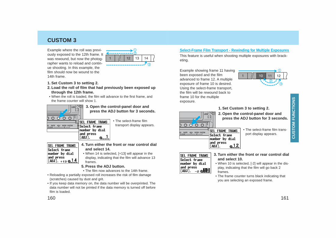
161160
CUSTOM 3
Example where the roll was previ-ously exposed to the 12th frame. Itwas rewound, but now the photog-rapher wants to reload and contin-ue shooting. In this example, thefilm should now be wound to the14th frame.
1. Set Custom 3 to setting 2.2. Load the roll of film that had previously been exposed up
through the 12th frame.• When the roll is loaded, the film will advance to the first frame, and
the frame counter will show 1.
3. Open the control-panel door andpress the ADJ button for 3 seconds.
• The select-frame filmtransport display appears.
4. Turn either the front or rear control dialand select 14.
• When 14 is selected, [+13] will appear in thedisplay, indicating that the film will advance 13frames.
5. Press the ADJ button.• The film now advances to the 14th frame.
• Reloading a partially exposed roll increases the risk of film damage(scratches) caused by dust and grit.
• If you keep data memory on, the data number will be overprinted. Thedata number will not be printed if the data memory is turned off beforefilm is loaded.
Select-Frame Film Transport - Rewinding for Multiple ExposuresThis feature is useful when shooting multiple exposures with brack-eting.
Example showing frame 11 havingbeen exposed and the filmadvanced to frame 12. A multipleexposure of frame 10 is desired.Using the select-frame transport,the film will be rewound back toframe 10 for the multipleexposure.
1. Set Custom 3 to setting 2.2. Open the control-panel door and
press the ADJ button for 3 seconds.
• The select-frame film trans-port display appears.
3. Turn either the front or rear control dialand select 10.
• When 10 is selected, [-2] will appear in the dis-play, indicating that the film will go back 2frames.
• The frame counter turns black indicating thatyou are selecting an exposed frame.
CU
STO
M F
UN
CT
ION
S
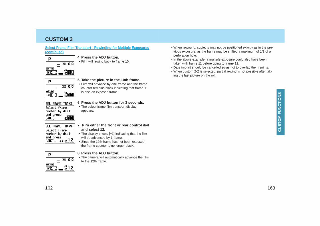
163162
CUSTOM 3
Select-Frame Film Transport - Rewinding for Multiple Exposures(continued)
4. Press the ADJ button.• Film will rewind back to frame 10.
5. Take the picture in the 10th frame.• Film will advance by one frame and the frame
counter remains black indicating that frame 11is also an exposed frame.
6. Press the ADJ button for 3 seconds.• The select-frame film transport display
appears.
7. Turn either the front or rear control dialand select 12.
• The display shows [+1] indicating that the filmwill be advanced by 1 frame.
• Since the 12th frame has not been exposed,the frame counter is no longer black.
8. Press the ADJ button.• The camera will automatically advance the film
to the 12th frame.
• When rewound, subjects may not be positioned exactly as in the pre-vious exposure, as the frame may be shifted a maximum of 1/2 of aperforation hole.
• In the above example, a multiple exposure could also have beentaken with frame 11 before going to frame 12.
• Date imprint should be cancelled so as not to overlap the imprints.• When custom 2-2 is selected, partial rewind is not possible after tak-
ing the last picture on the roll.
CU
STO
M F
UN
CT
ION
S
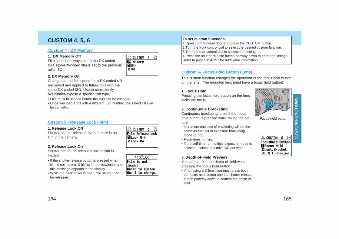
165164
CUSTOM 4, 5, 6
Custom 4 - DX Memory1. DX Memory OffFilm speed is always set to the DX-codedISO. Non-DX-coded film is set to the previousroll’s ISO.
2. DX Memory OnChanges to the film speed for a DX-coded rollare saved and applied to future rolls with thesame DX coded ISO. Use to consistentlyover/under-expose a specific film type.
Custom 5 - Release Lock (Film)
1. Release Lock OffShutter can be released even if there is nofilm in the camera.
2. Release Lock OnShutter cannot be released unless film isloaded.• If the shutter-release button is pressed when
film is not loaded, 0 blinks in the viewfinder andthis message appears in the display.
• While the back cover is open, the shutter canbe released.
Custom 6- Focus-Hold Button (Lens)
1. Focus HoldPressing the focus-hold button on the lenslocks the focus.
2. Continuous BracketingContinuous bracketing is set if the focushold button is pressed while taking the pic-ture. • Increment and size of bracketing will be the
same as that set in exposure bracketingmode (p. 92).
• Flash does not fire.• If the self-timer or multiple exposure mode is
selected, continuous drive will not work.
3. Depth-of-Field PreviewYou can confirm the depth-of-field whilepressing the focus hold button.• If not using a D lens, you must press both
the focus-hold button and the shutter-releasebutton partway down to confirm the depth-of-field.
Focus-hold button
To set custom functions;1.Open control-panel door and press the CUSTOM button.2.Turn the front control dial to select the desired custom function.3.Turn the rear control dial to seclect the setting.4.Press the shutter-release button partway down to enter the setings. Refer to pages 154-157 for additional information.
This custom function changes the operation of the focus hold buttonon the lens. (The mounted lens must have a focus hold button).
• Film must be loaded before the ISO can be changed.• Once you load a roll with a different ISO number, the saved ISO will
be cancelled.
CU
STO
M F
UN
CT
ION
S
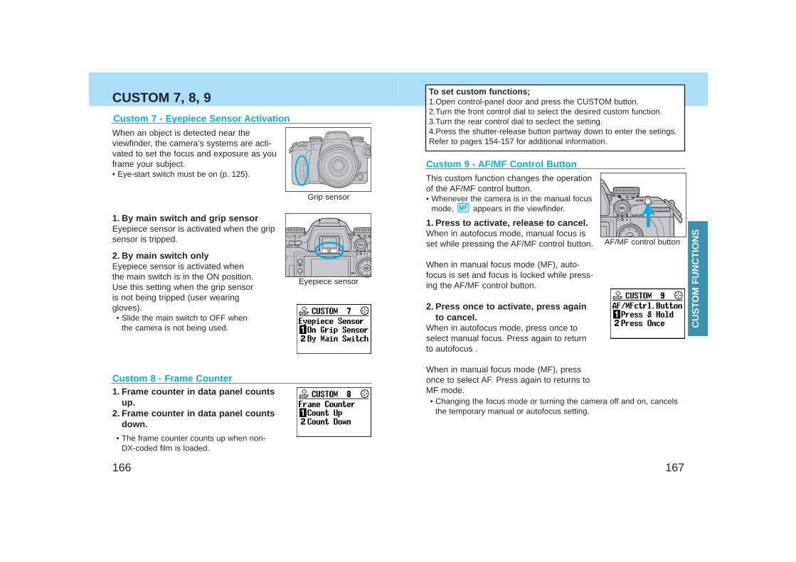
167166
CUSTOM 7, 8, 9
Custom 8 - Frame Counter1. Frame counter in data panel counts
up.2. Frame counter in data panel counts
down.
• The frame counter counts up when non-DX-coded film is loaded.
Custom 7 - Eyepiece Sensor Activation
1. By main switch and grip sensorEyepiece sensor is activated when the gripsensor is tripped.
2. By main switch onlyEyepiece sensor is activated whenthe main switch is in the ON position.Use this setting when the grip sensoris not being tripped (user wearinggloves).• Slide the main switch to OFF when
the camera is not being used.
When an object is detected near theviewfinder, the camera’s systems are acti-vated to set the focus and exposure as youframe your subject.• Eye-start switch must be on (p. 125).
Grip sensor
Eyepiece sensor
To set custom functions;1.Open control-panel door and press the CUSTOM button.2.Turn the front control dial to select the desired custom function.3.Turn the rear control dial to seclect the setting.4.Press the shutter-release button partway down to enter the setings. Refer to pages 154-157 for additional information.
Custom 9 - AF/MF Control Button
AF/MF control button
This custom function changes the operationof the AF/MF control button.• Whenever the camera is in the manual focus
mode, appears in the viewfinder.
1. Press to activate, release to cancel.When in autofocus mode, manual focus isset while pressing the AF/MF control button.
When in manual focus mode (MF), auto-focus is set and focus is locked while press-ing the AF/MF control button.
2. Press once to activate, press againto cancel.
When in autofocus mode, press once toselect manual focus. Press again to returnto autofocus .
When in manual focus mode (MF), pressonce to select AF. Press again to returns toMF mode.
CU
STO
M F
UN
CT
ION
S
• Changing the focus mode or turning the camera off and on, cancelsthe temporary manual or autofocus setting.
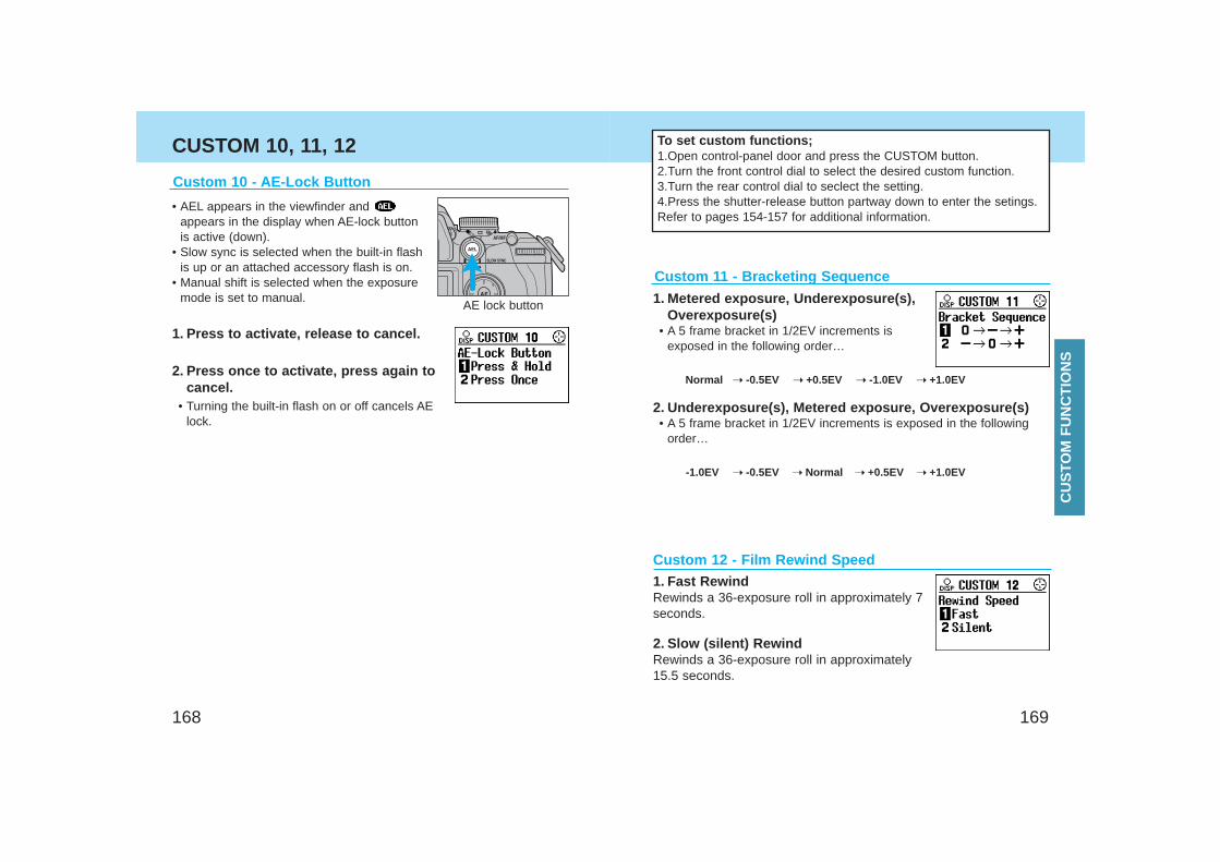
169168
CUSTOM 10, 11, 12 To set custom functions;1.Open control-panel door and press the CUSTOM button.2.Turn the front control dial to select the desired custom function.3.Turn the rear control dial to seclect the setting.4.Press the shutter-release button partway down to enter the setings. Refer to pages 154-157 for additional information.
AE lock button
Custom 10 - AE-Lock Button
• AEL appears in the viewfinder and appears in the display when AE-lock buttonis active (down).
• Slow sync is selected when the built-in flashis up or an attached accessory flash is on.
• Manual shift is selected when the exposuremode is set to manual.
1. Press to activate, release to cancel.
2. Press once to activate, press again tocancel.
• Turning the built-in flash on or off cancels AElock.
Custom 11 - Bracketing Sequence
1. Metered exposure, Underexposure(s),Overexposure(s)
• A 5 frame bracket in 1/2EV increments isexposed in the following order…
Normal ➝ -0.5EV ➝ +0.5EV ➝ -1.0EV ➝ +1.0EV
2. Underexposure(s), Metered exposure, Overexposure(s)• A 5 frame bracket in 1/2EV increments is exposed in the following
order…
-1.0EV ➝ -0.5EV ➝ Normal ➝ +0.5EV ➝ +1.0EV
Custom 12 - Film Rewind Speed1. Fast RewindRewinds a 36-exposure roll in approximately 7seconds.
2. Slow (silent) RewindRewinds a 36-exposure roll in approximately15.5 seconds.
CU
STO
M F
UN
CT
ION
S
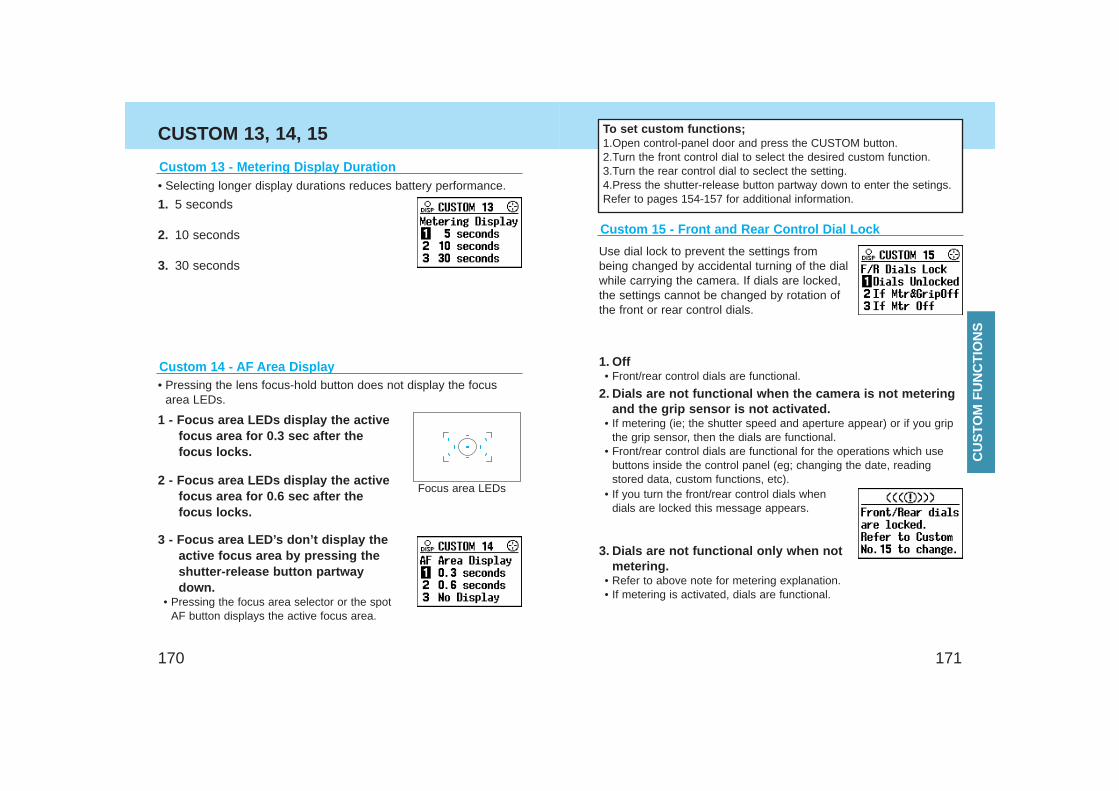
171
CUSTOM 13, 14, 15 To set custom functions;1.Open control-panel door and press the CUSTOM button.2.Turn the front control dial to select the desired custom function.3.Turn the rear control dial to seclect the setting.4.Press the shutter-release button partway down to enter the setings. Refer to pages 154-157 for additional information.
Custom 14 - AF Area Display• Pressing the lens focus-hold button does not display the focus
area LEDs.
2 - Focus area LEDs display the activefocus area for 0.6 sec after thefocus locks.
3 - Focus area LED’s don’t display theactive focus area by pressing theshutter-release button partwaydown.
• Pressing the focus area selector or the spotAF button displays the active focus area.
1 - Focus area LEDs display the activefocus area for 0.3 sec after thefocus locks.
Focus area LEDs
Custom 15 - Front and Rear Control Dial Lock
Use dial lock to prevent the settings frombeing changed by accidental turning of the dialwhile carrying the camera. If dials are locked,the settings cannot be changed by rotation ofthe front or rear control dials.
1. Off• Front/rear control dials are functional.
2. Dials are not functional when the camera is not meteringand the grip sensor is not activated.
• If metering (ie; the shutter speed and aperture appear) or if you gripthe grip sensor, then the dials are functional.
• Front/rear control dials are functional for the operations which usebuttons inside the control panel (eg; changing the date, readingstored data, custom functions, etc).
170
• Selecting longer display durations reduces battery performance.
Custom 13 - Metering Display Duration
1. 5 seconds
2. 10 seconds
3. 30 seconds
• If you turn the front/rear control dials whendials are locked this message appears.
3. Dials are not functional only when notmetering.
• Refer to above note for metering explanation.• If metering is activated, dials are functional.
CU
STO
M F
UN
CT
ION
S

1. Shutter cannot be released if a lens isnot attached.
• [- -] appears when the shutter button ispressed partway down, and then this messageappears when all the way down.
2. Shutter can be released if a lens is notattached.
• Use when mounting the lens to a non-couplinglens mount (telescope, microscope etc).
173172
CUSTOM 16, 17, 18
Custom 17 - AF Drive Speed1 - Fast • AF will operate at the maximum speed.
2 - Slow • For use in close-up or low light conditions.
1. Default operation
2. Exposure compensation using rear control dial (P A - aper-ture in P mode)
Control Dial Tasking
PS - shutter speed
Aperture
Shutter speed
Front Control Dial Rear Control DialExposure
Mode
P - Mode
A - Mode
S - Mode
PA - aperture
Aperture
Shutter speed
Control Dial Tasking
PA - aperture
Aperture
Shutter speed
Front Control Dial Rear Control DialExposure
Mode
P - Mode
A - Mode
S - Mode
Exposure
compensation
Exposure compensation is not possible using the rear control dial.
Custom 18 - Exposure Compensation Using the RearControl Dial in P, A, and S Mode
You can compensate the exposure using therear control dial. This is convenient when youare using a heavy lens and want to use yourleft hand to support it.
In P/A/S mode, exposure compensation is possible using the rearcontrol dial.
• The exposure compensation value is displayed in the meter indexand the display.
• Exposure-compensation dial must be set to +/– 0.• Compensation range is +/– 3 EV for both 1/2 and 1/3 EV increments.
Custom 16 - Release Lock (Lens)
Continued on next page
• If you turn the front control dial in P mode, you can select aperture. CU
STO
M F
UN
CT
ION
S
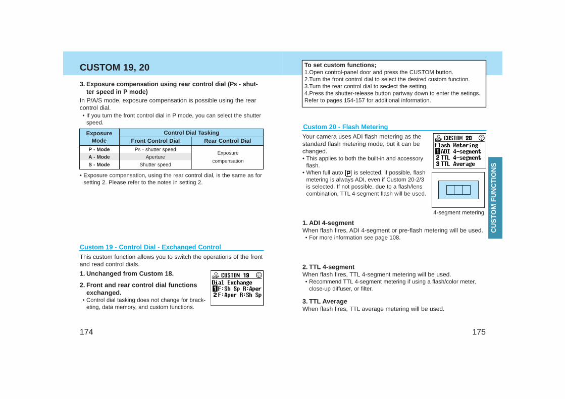
175174
CUSTOM 19, 20 To set custom functions;1.Open control-panel door and press the CUSTOM button.2.Turn the front control dial to select the desired custom function.3.Turn the rear control dial to seclect the setting.4.Press the shutter-release button partway down to enter the setings. Refer to pages 154-157 for additional information.
Custom 19 - Control Dial - Exchanged Control
1. Unchanged from Custom 18.
This custom function allows you to switch the operations of the frontand read control dials.
2. Front and rear control dial functionsexchanged.
• Control dial tasking does not change for brack-eting, data memory, and custom functions.
Custom 20 - Flash Metering
2. TTL 4-segmentWhen flash fires, TTL 4-segment metering will be used.• Recommend TTL 4-segment metering if using a flash/color meter,
close-up diffuser, or filter.
3. TTL AverageWhen flash fires, TTL average metering will be used.
Your camera uses ADI flash metering as thestandard flash metering mode, but it can bechanged.• This applies to both the built-in and accessory
flash.• When full auto is selected, if possible, flash
metering is always ADI, even if Custom 20-2/3is selected. If not possible, due to a flash/lenscombination, TTL 4-segment flash will be used.
1. ADI 4-segmentWhen flash fires, ADI 4-segment or pre-flash metering will be used.• For more information see page 108.
Control Dial Tasking
PS - shutter speed
Aperture
Shutter speed
Front Control Dial Rear Control DialExposure
Mode
P - Mode
A - Mode
S - Mode
Exposure
compensation
3. Exposure compensation using rear control dial (P S - shut-ter speed in P mode)
In P/A/S mode, exposure compensation is possible using the rearcontrol dial.
• Exposure compensation, using the rear control dial, is the same as forsetting 2. Please refer to the notes in setting 2.
• If you turn the front control dial in P mode, you can select the shutterspeed.
CU
STO
M F
UN
CT
ION
S
4-segment metering
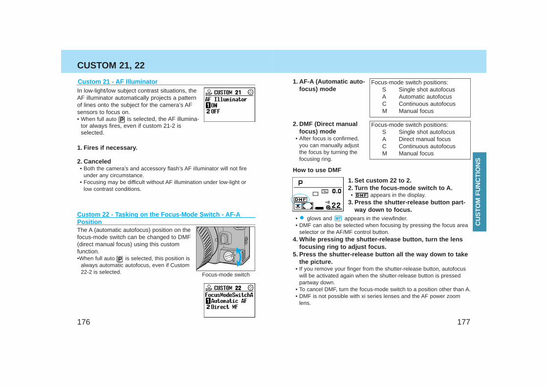
177176
CUSTOM 21, 22
Custom 22 - Tasking on the Focus-Mode Switch - AF-APositionThe A (automatic autofocus) position on thefocus-mode switch can be changed to DMF(direct manual focus) using this customfunction.•When full auto is selected, this position is
always automatic autofocus, even if Custom22-2 is selected.
1. AF-A (Automatic auto-focus) mode
2. DMF (Direct manualfocus) mode
• After focus is confirmed,you can manually adjustthe focus by turning thefocusing ring.
Focus-mode switch positions:S Single shot autofocusA Automatic autofocusC Continuous autofocusM Manual focus
Focus-mode switch positions:S Single shot autofocusA Direct manual focusC Continuous autofocusM Manual focus
1. Set custom 22 to 2.2. Turn the focus-mode switch to A.• appears in the display.
3. Press the shutter-release button part-way down to focus.
• glows and appears in the viewfinder.• DMF can also be selected when focusing by pressing the focus area
selector or the AF/MF control button. 4. While pressing the shutter-release button, turn the lens
focusing ring to adjust focus.5. Press the shutter-release button all the way down to take
the picture.• If you remove your finger from the shutter-release button, autofocus
will be activated again when the shutter-release button is pressedpartway down.
• To cancel DMF, turn the focus-mode switch to a position other than A.• DMF is not possible with xi series lenses and the AF power zoom
lens.
Focus-mode switch
How to use DMF
Custom 21 - AF IlluminatorIn low-light/low subject contrast situations, theAF illuminator automatically projects a patternof lines onto the subject for the camera’s AFsensors to focus on.• When full auto is selected, the AF illumina-
tor always fires, even if custom 21-2 isselected.
1. Fires if necessary.
2. Canceled• Both the camera’s and accessory flash’s AF iIluminator will not fire
under any circumstance.• Focusing may be difficult without AF illumination under low-light or
low contrast conditions.
CU
STO
M F
UN
CT
ION
S
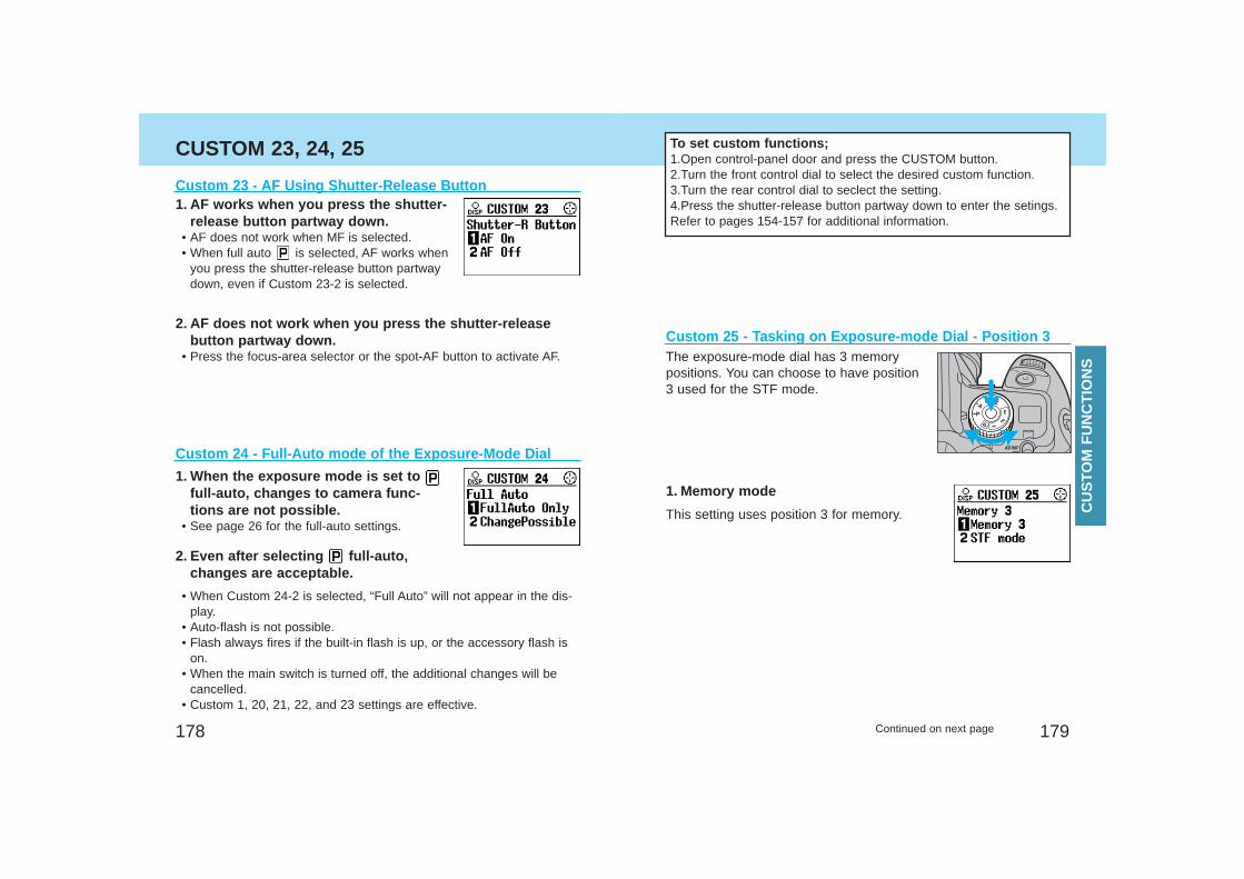
179
CUSTOM 23, 24, 25
Custom 24 - Full-Auto mode of the Exposure-Mode Dial
1. When the exposure mode is set to full-auto, changes to camera func-tions are not possible.
• See page 26 for the full-auto settings.
2. Even after selecting full-auto,changes are acceptable.
Custom 25 - Tasking on Exposure-mode Dial - Position 3The exposure-mode dial has 3 memorypositions. You can choose to have position3 used for the STF mode.
This setting uses position 3 for memory.
1. Memory mode
178
Custom 23 - AF Using Shutter-Release Button
2. AF does not work when you press the shutter-releasebutton partway down.
• Press the focus-area selector or the spot-AF button to activate AF.
1. AF works when you press the shutter-release button partway down.
• AF does not work when MF is selected.• When full auto is selected, AF works when
you press the shutter-release button partwaydown, even if Custom 23-2 is selected.
To set custom functions;1.Open control-panel door and press the CUSTOM button.2.Turn the front control dial to select the desired custom function.3.Turn the rear control dial to seclect the setting.4.Press the shutter-release button partway down to enter the setings. Refer to pages 154-157 for additional information.
Continued on next page
• When Custom 24-2 is selected, “Full Auto” will not appear in the dis-play.
• Auto-flash is not possible.• Flash always fires if the built-in flash is up, or the accessory flash is
on.• When the main switch is turned off, the additional changes will be
cancelled.• Custom 1, 20, 21, 22, and 23 settings are effective.
CU
STO
M F
UN
CT
ION
S
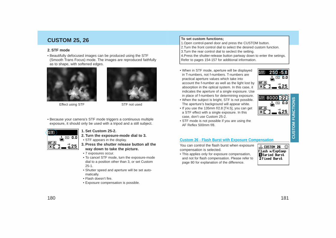
181180
CUSTOM 25, 26
Custom 26 - Flash Burst with Exposure CompensationYou can control the flash burst when exposurecompensation is selected. • This applies only for exposure compensation,
and not for flash compensation. Please refer topage 80 for explanation of the difference.
• When in STF mode, aperture will be displayedin T-numbers, not f-numbers. T-numbers arepractical aperture values which take intoaccount the f-number as well as the light lost byabsorption in the optical system. In this case, itindicates the aperture of a single exposure. Usein place of f-numbers for determining exposure.
• When the subject is bright, STF is not possible.The aperture’s background will appear white.
• If you use the 135mm f/2.8 [T4.5], you can geta STF effect with a single exposure. In thiscase, don’t use Custom 25-2.
• STF mode is not possible if you are using theAF Reflex 500mm f/8.
• Because your camera’s STF mode triggers a continuous multipleexposure, it should only be used with a tripod and a still subject.
1. Set Custom 25-2.2. Turn the exposure-mode dial to 3.• STF appears in the display.
3. Press the shutter release button all theway down to take the picture.
• 7 exposures occur.• To cancel STF mode, turn the exposure-mode
dial to a position other than 3, or set Custom25-1.
• Shutter speed and aperture will be set auto-matically.
• Flash doesn’t fire.• Exposure compensation is possible.
To set custom functions;1.Open control-panel door and press the CUSTOM button.2.Turn the front control dial to select the desired custom function.3.Turn the rear control dial to seclect the setting.4.Press the shutter-release button partway down to enter the setings. Refer to pages 154-157 for additional information.
Effect using STF STF not used
2. STF mode• Beautifully defocused images can be produced using the STF
(Smooth Trans Focus) mode. The images are reproduced faithfullyas to shape, with softened edges.
CU
STO
M F
UN
CT
ION
S
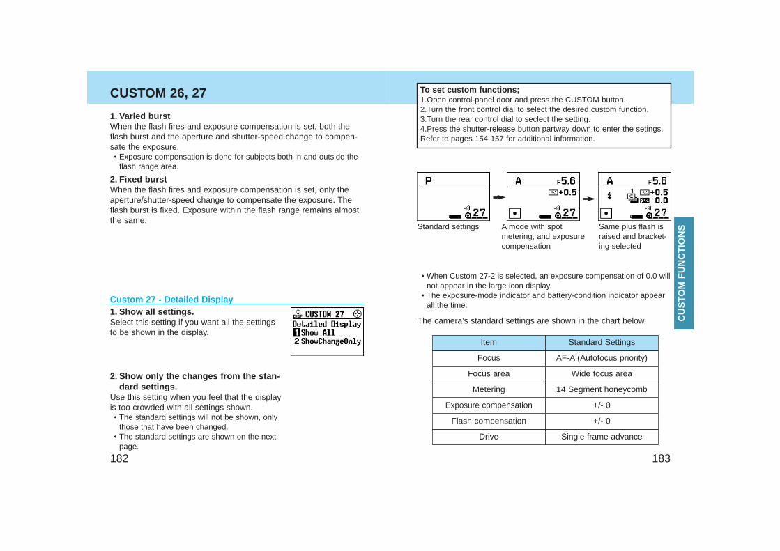
183182
Focus AF-A (Autofocus priority)
Focus area Wide focus area
Metering 14 Segment honeycomb
Exposure compensation +/- 0
Flash compensation +/- 0
Drive Single frame advance
Item Standard Settings
The camera’s standard settings are shown in the chart below.
To set custom functions;1.Open control-panel door and press the CUSTOM button.2.Turn the front control dial to select the desired custom function.3.Turn the rear control dial to seclect the setting.4.Press the shutter-release button partway down to enter the setings. Refer to pages 154-157 for additional information.
CUSTOM 26, 27
Custom 27 - Detailed Display1. Show all settings.Select this setting if you want all the settingsto be shown in the display.
2. Show only the changes from the stan-dard settings.
Use this setting when you feel that the displayis too crowded with all settings shown.• The standard settings will not be shown, only
those that have been changed.• The standard settings are shown on the next
page.
Standard settings A mode with spotmetering, and exposurecompensation
Same plus flash israised and bracket-ing selected
• When Custom 27-2 is selected, an exposure compensation of 0.0 willnot appear in the large icon display.
• The exposure-mode indicator and battery-condition indicator appearall the time.
2. Fixed burstWhen the flash fires and exposure compensation is set, only theaperture/shutter-speed change to compensate the exposure. Theflash burst is fixed. Exposure within the flash range remains almostthe same.
1. Varied burstWhen the flash fires and exposure compensation is set, both theflash burst and the aperture and shutter-speed change to compen-sate the exposure.• Exposure compensation is done for subjects both in and outside the
flash range area.
CU
STO
M F
UN
CT
ION
S
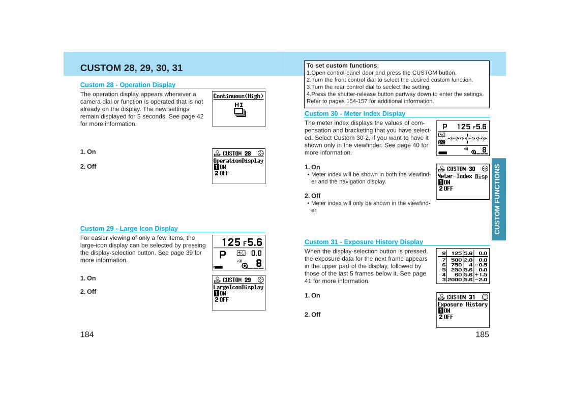
185184
CUSTOM 28, 29, 30, 31
Custom 31 - Exposure History Display
1. On
2. Off
When the display-selection button is pressed,the exposure data for the next frame appearsin the upper part of the display, followed bythose of the last 5 frames below it. See page41 for more information.
To set custom functions;1.Open control-panel door and press the CUSTOM button.2.Turn the front control dial to select the desired custom function.3.Turn the rear control dial to seclect the setting.4.Press the shutter-release button partway down to enter the setings. Refer to pages 154-157 for additional information.
Custom 30 - Meter Index DisplayThe meter index displays the values of com-pensation and bracketing that you have select-ed. Select Custom 30-2, if you want to have itshown only in the viewfinder. See page 40 formore information.
1. On• Meter index will be shown in both the viewfind-
er and the navigation display.
2. Off• Meter index will only be shown in the viewfind-
er.
Custom 29 - Large Icon DisplayFor easier viewing of only a few items, thelarge-icon display can be selected by pressingthe display-selection button. See page 39 formore information.
1. On
2. Off
Custom 28 - Operation DisplayThe operation display appears whenever acamera dial or function is operated that is notalready on the display. The new settingsremain displayed for 5 seconds. See page 42for more information.
1. On
2. Off
CU
STO
M F
UN
CT
ION
S
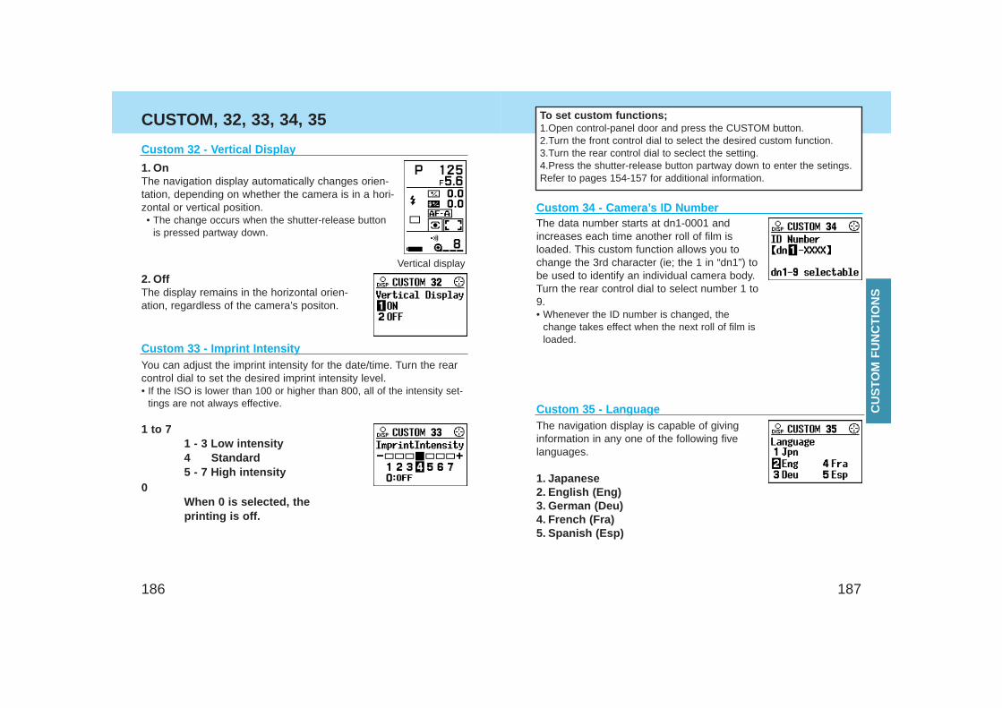
187186
CUSTOM, 32, 33, 34, 35
Custom 35 - Language The navigation display is capable of givinginformation in any one of the following five languages.
1. Japanese2. English (Eng)3. German (Deu)4. French (Fra) 5. Spanish (Esp)
Custom 34 - Camera’s ID Number The data number starts at dn1-0001 andincreases each time another roll of film isloaded. This custom function allows you tochange the 3rd character (ie; the 1 in “dn1”) tobe used to identify an individual camera body.Turn the rear control dial to select number 1 to9.• Whenever the ID number is changed, the
change takes effect when the next roll of film isloaded.
Custom 33 - Imprint Intensity
1 to 7 1 - 3 Low intensity4 Standard5 - 7 High intensity
0 When 0 is selected, the printing is off.
You can adjust the imprint intensity for the date/time. Turn the rearcontrol dial to set the desired imprint intensity level. • If the ISO is lower than 100 or higher than 800, all of the intensity set-
tings are not always effective.
Custom 32 - Vertical Display
2. OffThe display remains in the horizontal orien-ation, regardless of the camera’s positon.
1. On The navigation display automatically changes orien-tation, depending on whether the camera is in a hori-zontal or vertical position.• The change occurs when the shutter-release button
is pressed partway down.
Vertical display
To set custom functions;1.Open control-panel door and press the CUSTOM button.2.Turn the front control dial to select the desired custom function.3.Turn the rear control dial to seclect the setting.4.Press the shutter-release button partway down to enter the setings. Refer to pages 154-157 for additional information.
CU
STO
M F
UN
CT
ION
S
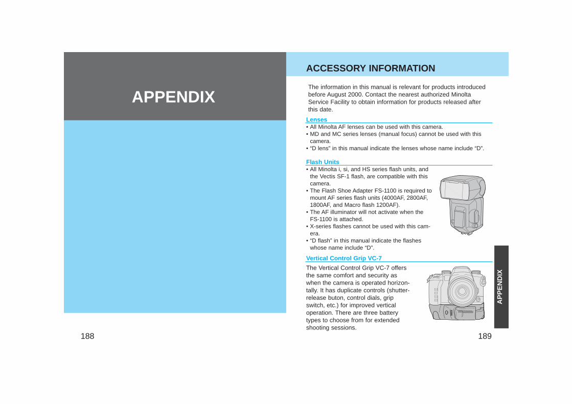
189188
ACCESSORY INFORMATION
Lenses• All Minolta AF lenses can be used with this camera.• MD and MC series lenses (manual focus) cannot be used with this
camera.• “D lens” in this manual indicate the lenses whose name include “D”.
Vertical Control Grip VC-7
The information in this manual is relevant for products introducedbefore August 2000. Contact the nearest authorized MinoltaService Facility to obtain information for products released afterthis date.
Flash Units• All Minolta i, si, and HS series flash units, and
the Vectis SF-1 flash, are compatible with thiscamera.
• The Flash Shoe Adapter FS-1100 is required tomount AF series flash units (4000AF, 2800AF,1800AF, and Macro flash 1200AF).
• The AF illuminator will not activate when theFS-1100 is attached.
• X-series flashes cannot be used with this cam-era.
• “D flash” in this manual indicate the flasheswhose name include “D”.
The Vertical Control Grip VC-7 offersthe same comfort and security aswhen the camera is operated horizon-tally. It has duplicate controls (shutter-release buton, control dials, gripswitch, etc.) for improved verticaloperation. There are three batterytypes to choose from for extendedshooting sessions.
AP
PE
ND
IX
APPENDIX
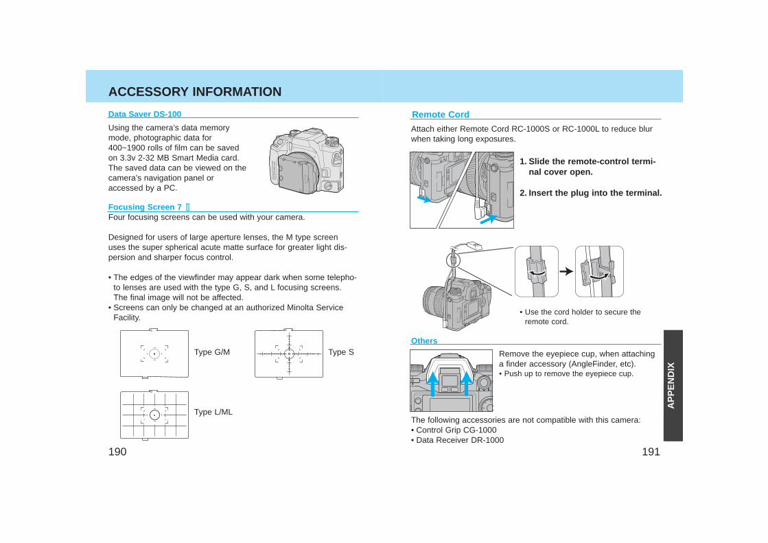
191190
ACCESSORY INFORMATION
Focusing Screen 7 Four focusing screens can be used with your camera.
Designed for users of large aperture lenses, the M type screenuses the super spherical acute matte surface for greater light dis-persion and sharper focus control.
• The edges of the viewfinder may appear dark when some telepho-to lenses are used with the type G, S, and L focusing screens.The final image will not be affected.
• Screens can only be changed at an authorized Minolta ServiceFacility.
Type G/M Type S
Type L/ML
Others
Remove the eyepiece cup, when attachinga finder accessory (AngleFinder, etc).• Push up to remove the eyepiece cup.
The following accessories are not compatible with this camera:• Control Grip CG-1000• Data Receiver DR-1000
Using the camera’s data memorymode, photographic data for400~1900 rolls of film can be savedon 3.3v 2-32 MB Smart Media card.The saved data can be viewed on thecamera’s navigation panel oraccessed by a PC.
Data Saver DS-100 Remote Cord
Attach either Remote Cord RC-1000S or RC-1000L to reduce blurwhen taking long exposures.
1. Slide the remote-control termi-nal cover open.
2. Insert the plug into the terminal.
• Use the cord holder to secure theremote cord.
AP
PE
ND
IX
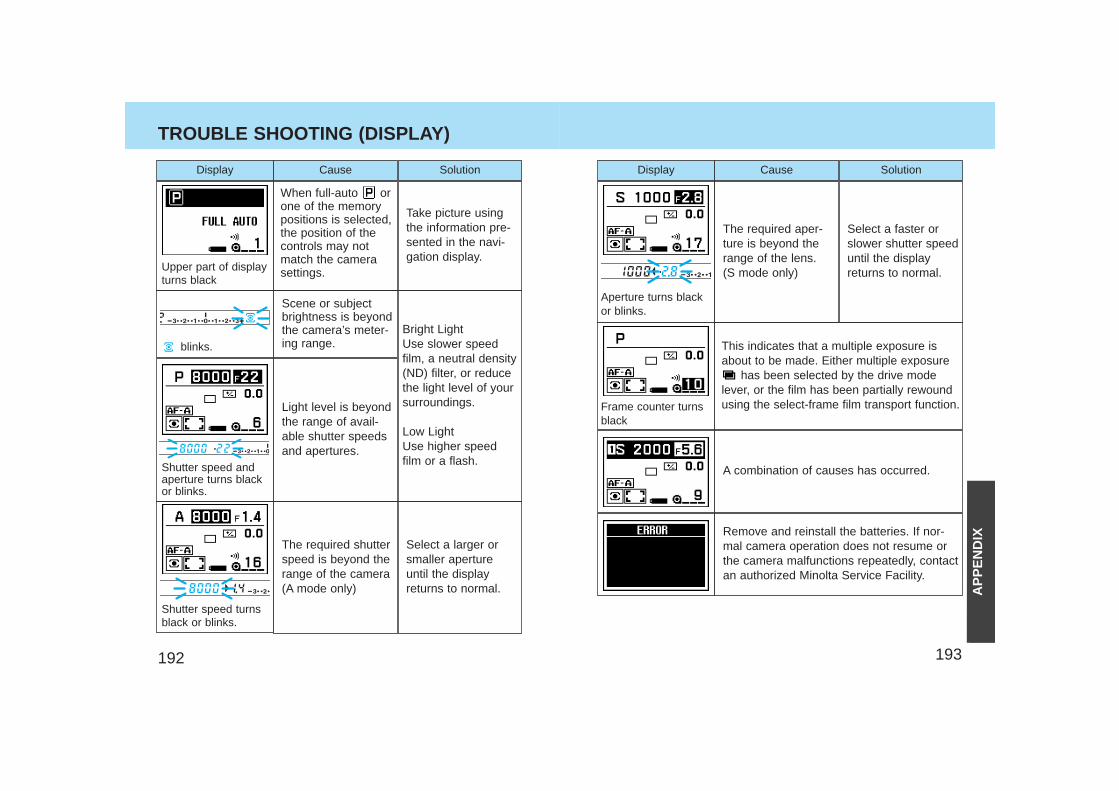
193192
TROUBLE SHOOTING (DISPLAY)
Display Solution
Scene or subjectbrightness is beyondthe camera’s meter-ing range.
Light level is beyondthe range of avail-able shutter speedsand apertures.
When full-auto orone of the memorypositions is selected,the position of thecontrols may notmatch the camerasettings.
The required shutterspeed is beyond therange of the camera(A mode only)
Bright Light Use slower speedfilm, a neutral density(ND) filter, or reducethe light level of yoursurroundings.
Low LightUse higher speedfilm or a flash.
Take picture usingthe information pre-sented in the navi-gation display.
Select a larger orsmaller apertureuntil the displayreturns to normal.
Display Cause Solution
This indicates that a multiple exposure isabout to be made. Either multiple exposure
has been selected by the drive modelever, or the film has been partially rewoundusing the select-frame film transport function.
A combination of causes has occurred.
The required aper-ture is beyond therange of the lens. (S mode only)
Remove and reinstall the batteries. If nor-mal camera operation does not resume orthe camera malfunctions repeatedly, contactan authorized Minolta Service Facility.
Select a faster orslower shutter speeduntil the displayreturns to normal.
Shutter speed andaperture turns blackor blinks.
Shutter speed turnsblack or blinks.
Upper part of displayturns black
blinks.
Frame counter turnsblack
Aperture turns blackor blinks.
Cause
AP
PE
ND
IX
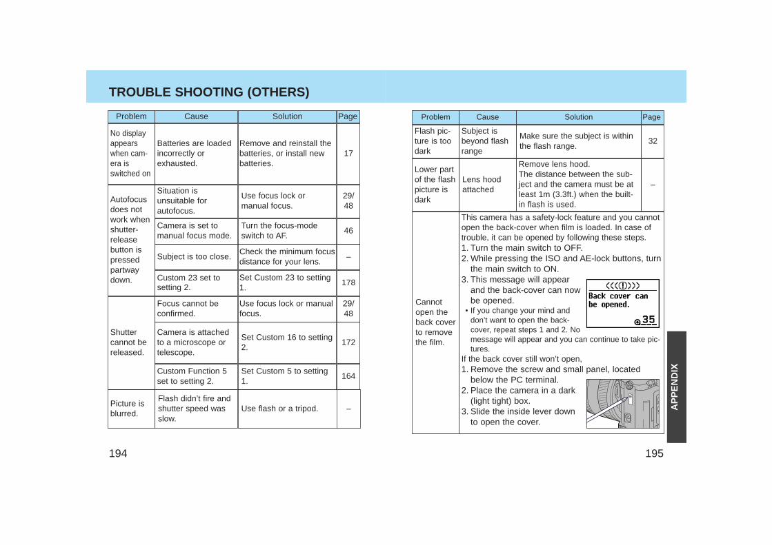
195194
Problem Cause Solution
Shuttercannot bereleased.
Autofocusdoes notwork whenshutter-releasebutton ispressedpartwaydown.
Focus cannot beconfirmed.
Camera is attachedto a microscope ortelescope.
Turn the focus-modeswitch to AF.
Use focus lock ormanual focus.
Set Custom 16 to setting2.
Page
–
178
29/48
172
Custom Function 5set to setting 2.
Set Custom 5 to setting1.
164
Check the minimum focusdistance for your lens.
Set Custom 23 to setting1.
Use focus lock or manualfocus.
29/48
Problem Cause Solution
Lens hoodattached
Cannotopen theback coverto removethe film.
Flash pic-ture is toodark
Lower partof the flashpicture isdark
This camera has a safety-lock feature and you cannotopen the back-cover when film is loaded. In case oftrouble, it can be opened by following these steps.1. Turn the main switch to OFF.2. While pressing the ISO and AE-lock buttons, turn
the main switch to ON.3. This message will appear
and the back-cover can nowbe opened.
• If you change your mind anddon’t want to open the back-cover, repeat steps 1 and 2. Nomessage will appear and you can continue to take pic-tures.
If the back cover still won’t open,1. Remove the screw and small panel, located
below the PC terminal.2. Place the camera in a dark
(light tight) box.3. Slide the inside lever down
to open the cover.
Subject isbeyond flashrange
Make sure the subject is withinthe flash range.
Page
–
32
Remove lens hood.The distance between the sub-ject and the camera must be atleast 1m (3.3ft.) when the built-in flash is used.
TROUBLE SHOOTING (OTHERS)
Subject is too close.
Custom 23 set tosetting 2.
17Remove and reinstall thebatteries, or install newbatteries.
Batteries are loadedincorrectly orexhausted.
No displayappearswhen cam-era isswitched on
Situation isunsuitable forautofocus.
Camera is set tomanual focus mode.
46
Picture isblurred.
Flash didn’t fire andshutter speed wasslow.
Use flash or a tripod. – AP
PE
ND
IX
197196
CARE AND STORAGE
• This camera is designed for use from –20 to 50 °C (4 to 122 °F).• Never leave your camera where it may be subjected to extreme
temperatures such as the glove compartment of a car.• Data panel response time will be slow at colder temperatures. The
display will temporarily darken at higher temperatures, but willrestore when the temperature normalizes.
• This camera is not waterproof or splashproof. When using thecamera in the rain, protect the camera and the lens.
• Never subject the camera to extreme humidity.• To prevent condensation from forming, place the camera in a
sealed plastic bag when bringing it from cold environment to awarm environment. Allow it to come to room temperature beforeremoving it from the bag.
• A low-battery indicator may appear even with fresh batteriesdepending on the storage conditions. To restore camera power,repeat turning the camera on and off.
• Battery capacity decreases at colder temperatures. A half or low-battery indicator may appear even with fresh batteries, so keepyour camera and spare batteries in a warm inside pocket whenshooting in cold weather. Batteries will regain some of their capac-ity when warmed to normal operating temperature.
Operating Temperature and Conditions
StorageWhen storing your camera for extended periods,• Always attach the protective caps.• Store in a cool, dry, and well-ventilated area away from dust and
chemicals such as moth balls. For long periods, place the camerain an airtight container with a silica gel drying agent.
• Periodically release the camera’s shutter to keep it operating prop-erly.
• Before using after prolonged storage, check the camera’s opera-tion to make sure it is functioning properly.
• Check the camera’s operation carefully, or take test photographs.• Minolta is not responsible for any loss that may occur due to an
equipment malfunction.
Before Important Events
Cleaning• If the camera or lens barrel is dirty, wipe it gently with a soft,
clean, dry cloth. If the camera or lens comes in contact with sand,gently blow away loose particles - wiping may scratch the surface.
• To clean the lens surface, first brush away any dust or sand then,if necessary, moisten a lens tissue with lens cleaning fluid andgently wipe the lens in a circular motion, starting from the center.
• Never place lens fluid directly on the lens.• Never touch the interior of the camera, especially the shutter and
mirror, doing so may impair their alignment and movement.• Dust on the mirror will not affect the exposure but may affect the
focus. Use a blower brush to remove dust from or around the mir-ror.
• Never use compressed air to clean the camera’s interior, it maycause damage to sensitive interior parts.
• Never use organic solvents to clean the camera.• Never touch the lens surface with your fingers.
Questions and Service• If you have questions about your camera, contact your local camera
dealer or write to the Minolta distributor in your area.• Before shipping your camera for repair, please contact an authorized
Minolta Service Facility for details.
AP
PE
ND
IX
199198
SPECIFICATIONS
Camera Type: 35mm SLR with built-in flash, autoexposure(AE)
FocusType: 9 point TTL phase-detection system, multi
metering with dual cross-hair type CCD linesensor metering cell.Multi-dimensional predictive focus control isavailable for moving subjects.
AF Sensitivity Range: EV -1 to 18 (ISO 100)AF Illuminator: Built-in LED. Automatically activated in low-
light/ low-contrast situations.Range: 0.7 - 7m (With a standard 50mm lens.)
AF Control: Single-shot, continuous, automatic AF-modeselection. DMF mode is possible.
ExposureModes: P, A, S, M (PA/Ps available)Type: TTL metering; direct TTL metering for flashMetering Cell: 14-segment honeycomb-pattern SPC, 4-
segment flash-metering SPC for flashMetering Range : 14-segment metering: EV 0 - 20, (ISO 100, f/1.4 lens) Center weighted average: EV 0 - 20,
Spot metering: EV 3 - 20 Film-speed Setting: Automatic: ISO 25 to 5000 for DX-coded film.
Manual: ISO 6 to 6400 in 1/3 EV increments.Flash: ISO 25 - 1000.
ShutterType: Electronically-controlled, vertical-traverse,
focal-plane typeSpeeds: 30 sec. - 1/8000 sec., bulb (approximately 7
hours with fresh batteries).Flash sync speed: 1/200 or slower (synchronizes with all speeds
in HSS mode).
Built-in FlashGN: 12 (ISO 100 in meters)Coverage: 24mm angle of viewRecycling Time: Approx. 2 sec. (3.5 sec when red-eye reduction
or wireless/remote flash is used) - (according toMinolta test methods)
Modes: Fill-flash, Fill-flash with red-eye reduction,Flash Cancel, Wireless flash, Slow-sync, andRear-flash sync., Autoflash when full-auto isset.
ViewfinderType: Eye level fixed pentaprismField of view: Approx. 92% x 94% (with 50mm f/1.4 at ∞)Magnification: 0.8X (with 50mm lens f/1.4 at ∞)Focusing Screen: Spherical acute matteEye-Relief: 22.5 mm from the eyepiece, 18.5 mm from the
eyepiece frame.Diopter: –1 diopter, Adjustment: –2.5 - +0.5Film TransportDrive Modes: Single frame advance, Continuous advance
(Low 2 frames/sec., High 4 frames/sec, 3.7 inAF mode) , Self-timer (10 or 2 second),Exposure bracketing (single-frame orcontinuous advance), Multiple exposure.
Loading: Auto loadRewind: Auto rewind, manual start
Rewind time (24 exposure film): High speed:5.5 sec., Silent: 12 sec.
AP
PE
ND
IX
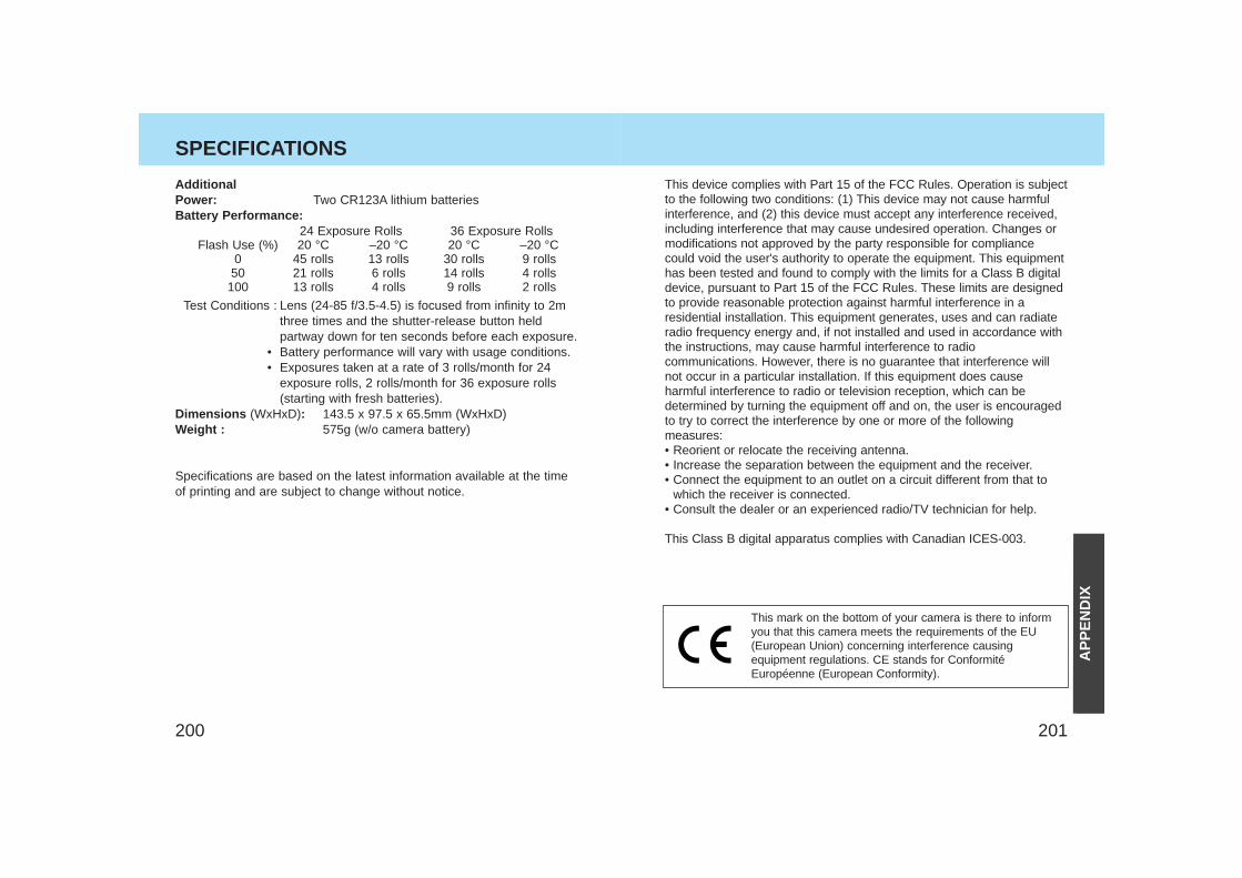
201200
AdditionalPower: Two CR123A lithium batteriesBattery Performance:
24 Exposure Rolls 36 Exposure RollsFlash Use (%) 20 °C –20 °C 20 °C –20 °C
0 45 rolls 13 rolls 30 rolls 9 rolls50 21 rolls 6 rolls 14 rolls 4 rolls
100 13 rolls 4 rolls 9 rolls 2 rolls
Test Conditions : Lens (24-85 f/3.5-4.5) is focused from infinity to 2mthree times and the shutter-release button heldpartway down for ten seconds before each exposure.
• Battery performance will vary with usage conditions.• Exposures taken at a rate of 3 rolls/month for 24
exposure rolls, 2 rolls/month for 36 exposure rolls(starting with fresh batteries).
Dimensions (WxHxD): 143.5 x 97.5 x 65.5mm (WxHxD)Weight : 575g (w/o camera battery)
Specifications are based on the latest information available at the timeof printing and are subject to change without notice.
SPECIFICATIONS
This device complies with Part 15 of the FCC Rules. Operation is subjectto the following two conditions: (1) This device may not cause harmfulinterference, and (2) this device must accept any interference received,including interference that may cause undesired operation. Changes ormodifications not approved by the party responsible for compliancecould void the user's authority to operate the equipment. This equipmenthas been tested and found to comply with the limits for a Class B digitaldevice, pursuant to Part 15 of the FCC Rules. These limits are designedto provide reasonable protection against harmful interference in aresidential installation. This equipment generates, uses and can radiateradio frequency energy and, if not installed and used in accordance withthe instructions, may cause harmful interference to radiocommunications. However, there is no guarantee that interference willnot occur in a particular installation. If this equipment does causeharmful interference to radio or television reception, which can bedetermined by turning the equipment off and on, the user is encouragedto try to correct the interference by one or more of the followingmeasures:• Reorient or relocate the receiving antenna.• Increase the separation between the equipment and the receiver.• Connect the equipment to an outlet on a circuit different from that to
which the receiver is connected.• Consult the dealer or an experienced radio/TV technician for help.
This Class B digital apparatus complies with Canadian ICES-003.
This mark on the bottom of your camera is there to informyou that this camera meets the requirements of the EU(European Union) concerning interference causingequipment regulations. CE stands for ConformitéEuropéenne (European Conformity).
AP
PE
ND
IX
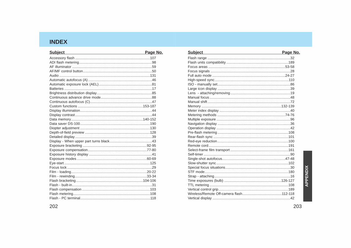
203202
INDEX
Accessory flash ............................................................................107ADI flash metering..........................................................................98AF illuminator .................................................................................59AF/MF control button......................................................................50Audio ............................................................................................131Automatic autofocus (A) .................................................................46 Automatic exposure lock (AEL)......................................................81Batteries .........................................................................................17Brightness distribution display........................................................85Continuous advance drive mode....................................................88Continuous autofocus (C)...............................................................47Custom functions ..................................................................153-187Display illumination.........................................................................44Display contrast..............................................................................44Data memory.........................................................................140-152Data saver DS-100.......................................................................190Diopter adjustment .......................................................................130Depth-of-field preview ..................................................................128Detailed display ..............................................................................39Display - When upper part turns black...........................................43Exposure bracketing .................................................................92-95Exposure compensation............................................................77-80Exposure history display ................................................................41Exposure modes .......................................................................60-69Eye-start .......................................................................................125Focus lock ......................................................................................29Film - loading.............................................................................20-22Film - rewinding.........................................................................33-34Flash bracketing....................................................................104-106Flash - built-in.................................................................................31Flash compensation .....................................................................103Flash metering..............................................................................108Flash - PC terminal.......................................................................118
Subject Page No.Flash range ....................................................................................32Flash units compatibility ...............................................................189Focus areas ..............................................................................53-58Focus signals .................................................................................28Full auto mode ..........................................................................24-27High-speed sync...........................................................................110ISO - manually set..........................................................................86Large icon display ..........................................................................39Lens - attaching/removing.............................................................19Manual focus ..................................................................................48Manual shift ....................................................................................72Memory .................................................................................132-139Meter index display ........................................................................40Metering methods .....................................................................74-76Multiple exposure ...........................................................................96Navigation display ..........................................................................36Operation display ...........................................................................42Pre-flash metering ........................................................................108Rear-flash sync ............................................................................101Red-eye reduction ........................................................................100Remote cord.................................................................................191Select-frame film transport ...........................................................161Self-timer ........................................................................................90Single-shot autofocus................................................................47-48Slow-shutter sync .........................................................................102Special focus situations..................................................................30STF mode.....................................................................................180Strap - attaching.............................................................................16Time exposures (bulb) ..........................................................126-127TTL metering ................................................................................108Vertical control grip.......................................................................189Wireless/Remote Off-camera flash........................................112-118Vertical display ...............................................................................42
Subject Page No.
AP
PE
ND
IX