dynamic analysis of spur gear transmissions (danst) · dynamic analysis of spur gear transmissions...
TRANSCRIPT
NASATechnical Memorandum 107291
Army Research Laboratory
Technical Report ARL-TR-1189
Dynamic Analysis of Spur GearTransmissions (DANST)PC Version 3.00 User Manual
Fred B. Oswald
Lewis Research Center
Cleveland, Ohio
Hsiang Hsi Lin
University of Memphis
Memphis, Tennessee
Irebert R. Delgado
Vehicle Propulsion Directorate
U.S. Army Research LaboratoryLewis Research Center
Cleveland, Ohio
August 1996
U,8. ARMY
Nat_o_tl M ronat_k_l and_¢e _lm I¢_tmtt_
https://ntrs.nasa.gov/search.jsp?R=19970003836 2018-06-04T09:40:55+00:00Z
DISCLAIMERNOTICE
THIS DOCUMENT I$ BEST
QUALITY AVAILABLE. THE
COPY FURNISHED TO DTIC
CONTAINED A SIGNIFICANT
NUMBER OF PAGES WHICH DO
NOT REPRODUCE LEGIBLY.

DYNAMIC ANALYSIS OF SPUR GEAR TRANSMISSIONS (DANST)PC Version 3.00 USER MANUAL
by
Fred B. Oswald
NASA Lewle Research Center
Cleveland, Ohl¢ 44135
I.Islang Hal LIn
University of Memphis
Memphis, Tenneesee 38152
and
In)belt R. Delgado
Vehicle Propulsion Oimctormte
US Army Research Laboratory
Cleveland, Ohio 44135
SUMMARY
DANST is a FORTRAN coa'rl_tcr program for static and dynamic analysis of spur gear systems. The program canbe used for para.ngu'ic studie_ to predict the static transmission error, dynamic load, tooth bending stress and otberproperties of spur gears as they age influenced by otmating speed, torque, stiffncss, damping, inertia, and toothprotSle.
DANST performs geometric modeling and dynamic analysis for }ow- of high-contact-ratio spur gears. DA,WSTcan simulate gear systems with contact ratios ranging from one to three. It was designed to be easy to use and it _sext=n_ively documented in several previous reports _nd by comments in the source code. This report de_ribesinstalling and using a .ew PC venion of DANST, covers input d_a requirements and pt'esonts examples.
PROGRAM CAPABILITIES
Dynamic Analysis of Spur Gear Transmissions (DANST) is a computer program for spur gear systen'n. Thepfosram calculates the propertiesof system components and substitutes them into the governing equations to solvefor dynarnh: tooth loads, tonth bending smesses and ocher engineering properties. DA,NST-PC runs on personaJcomputers with the following minimum requirengnts: 386 or later, 640 KU men_, co-prucessor, VGA graphics,
DOS operating system.
DANST is basedon a four-degree.of-freedom, lumped-mats model of t gear ttammission. The model includes
driving and driven gear_, connecting shafls, motor, and load. The equations of ruction were derived from basicgetr geometry and elementary vibration principles. "I_e dynamic mlution is found by integrating the equa*.i(lns ofmotion. References 1.]4 describe the model, method of solution and parsme_c smdie,s performed using DAI_ST.
DANST provides the user with n_my options including: (1) Materials, _ic Ig_Lrgeogx_t_, and operating
coalitions; (2) Varies ctwnbinations of tooth profiles (including three standard form_ of tip relief or user.digiti2ed_'oftle modificatiocu)_ (3) Stt_ti¢ and dynamic analysis; and (d) Various printed and plotted outputs.
DIFFERENCES FROM EARLIER VERSIONS
The previons vmions (through DANST 2.0x) were for mainly.me corn_ten_. DANST-PC runs on persoc_computers. DANST-PC improves modeling of tooth comact condif ons by c,onaidering that tooth de_ under
load extend._ the contact zone. (Contact extension can be _'es_l for compatibility with ptevions versions. Seethe notes below for the input variable boin.) DANST-PC adds the ability to model nou-standard tooth proportionsand non-standard c_*t di_mce. For optional uk-r-difitized tooth profiles, an external preprocessor program isno longer needed. The input data f¢,_'-m_has changed c_sider_ly for DANST-PC.
[N_t_! "DATA
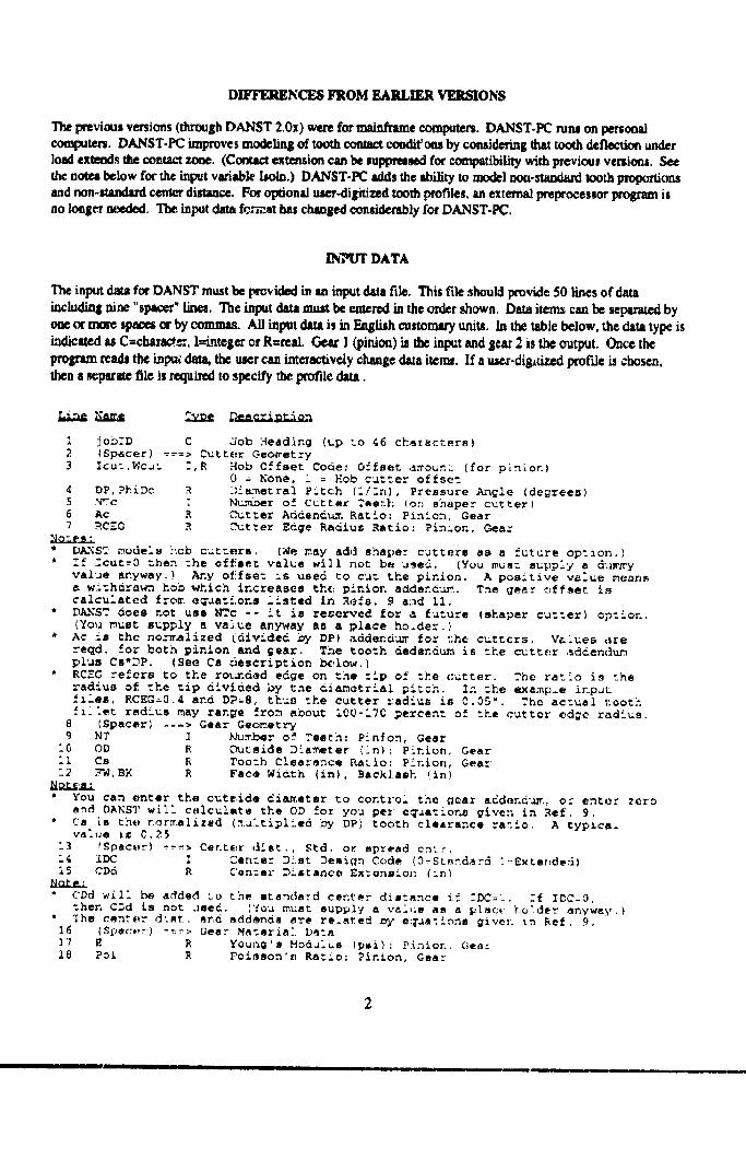
"I',e inpt_ data for DANST must be provided in an input aua file. This file should provide 50 lines of data
including nine "spacer '°lin_. The inlet data must be emered i, the order shown. Data iten_ can be sepurated by
one or mote spaces or by commas. All input dam is in Eaglith cestonmry units. In the table below, the data type isindictted u C=cluua_e:. I=integer or R=retl. Gear I (pinion) i_ the input end Sear 2 is the output. Once the
program reads the inpu_ dam, the surerca, interacdvely change data item,. H a user-digitized profde _ chosen,then a _'parate file is required to specify the [xofile data.
I job.-D C Job Headin9 (up _o 46 characters)
2. {Spacer) =--=> Cutt_:r Geometry
3 Icu=,WcJ= -',R Hob Offset Code; Offset amoun_ (for pinion)0 = None, i = Hob cutter offse-_
4 DP,?hiDc R D:_me--ral Pitch (i/ln], Pressure AnGle (de_rees)
5 N'Tc : Ntummer of Cutter ,"ee=h (on shaper cu_ter)
6 Ac R ,.Cut_er Addendu.T. Ratio: Pinion, Gear
7 RCE_ .R Cutter Edge Radius Ratio: ?isles, Gear
* DA.NST models hob cutters. [We may add shaper cutters as a future option.)
* :f =cut--0 then :he offset value will not be used. [You mus_ supply • dJ_ry
val-ue anyway.) Ar.y offset is used to cut the pinion. A positive value means
w.i=hdrawn hod which increases the pinion addend-.u_.. The gear offset iscalculated from. eqaatl.ons listed in Refs. 9 a:3d ii.
* DANST does not use NTc -- it is reserved for a fu--ure (shaper cu---er) option.
(You must supply a value anyway as a place he_def. )
* Ac is the no.-_alized (divided by DP) addend-,ur, for :.he cutters, Values dre
reqd. for beta pinion and gear. The tooth dedendum is --he cutter ,_ddendum
plus Ca"PP. (See Cs descriptxon b(,low.)
* RC-C re_ers to the rounded edge on the --ip of ".he (:utter. The ratio is the
radius of. the --ip dlvida4 by the ciam_trlal pi_ch. Z.% _he example in puu
files, RCEG=S.4 and DP=8, thus ".he cutter radius is C.05". The ac-ual tooth
fit:st radius may range from about 10O-17C _ercent of ".he cutter edge radius.
8 ISpacer) -==> Gear Geometry
9 NT ] Nu._/_ar o_ ?seth: P!nlon, Gear
i0 OD R Outside Dlame_er (_n}: Plnion, Gear
ii Cs R Tooth Clearance [_atio: Pinion, Gear
12 :-'W,BK R Face Width (An), Backlash !in)
* You can enter the cure, ida dla_.eter to control the _ear addendum., or enter zero
end DANST will calculate the OD for you per eqaations given in Ref. 9.
" Ca [s thi_ normalized (._:a[ltipl/.ed Dy DP) tooth clearance ratio. A typica.value iz C.25
"-3 _Epac_r) ---_> Center ,_ist., Std. or spread on'r.
14 IDC I Can-or Diet Design Code (_-Standar4 :-Exter,ded)
15 CDd R C'_n=sr Distance Ex:onslon (in)
* CDd will be added _.o the ata_da:d center d_atance if -PC= t. -'f ZDC-O,
-her. C_d is not Jsed. {You must supply a val,_s am a _Isc,, holder anyway.)
" _he csn'.'_r diet. m_,d addenda are re_ated Dy eq_anions givel. _n Re_. 9.16 (Spac:_r) -----;.Gear Materla:. Data
17 E R YOung'S Modulus (p_i) : Pinion, Gee:
18 Poi R Poisaon's Ra--io: Pinion, Gear
2
• I III I ill, -
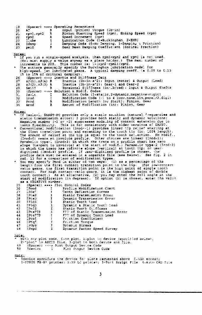
19 (Spacer) ===) O_eratlng Parameters
2C AT R Input (pinion) _orque (ib-in)
21 rpml,rpm2 _ Pinion Starting Speed (rpm), Ending Speed (rpm)
22 rpml R S_eed Increment (rp_)
23 Ziube I L_bricat_on Code (1-Bucklngham, 2=_HD)
24 Id_p i Damping Code (0=No Damping, l=Dampinw '_ Friction)
25 ps!G R Gear .Mesh D_ing Coefficient [decimal fraction)
_es:
* If you run a single-speed ana]ysis, =hen rpml_rpx2 and rpml is nor used.
(You must supply a value anyway as a place holder.) The max. n'_ber of
increments is 200. This n%unber is: i-_rpm2-rpml)/rpmI.
* The authors generally specify the Buckingham iv2mricatien model for
hlgh-speed, _et lubricated gears. A typical dam_ing coeff, is _.05 to C.15
(5 to 15% of critical damping).
26 (Spacer) ===> inertia and Stiffness Data
27 zJ(1),z3(4) R Inertia (Ib-in-a^2): Xnput (motor) & _=put (Load)
28 zJ(2),z2(3) R Inertia (Ib-in-s^2): Gear-i and Gear-2
29 Ss_if R Torsional Sllffness (in-lb/rad): Znput & Output Shafts
30 (Spacer) .... > Solution & Modlf. Codes
31 Isc_in Z Solution Code (l=static,2_dyr_mic,negative=rigidl
32 Zmod Z Modification Code (-i to 4 conv,none,lin,paral/2,di_i)
33 P_.od R Modlfication Length (or S:&rt): Pinion, Gear
34 A_od R Amount of Modification (in): Pinion, Gear
_UnL_n_
* If Isoln--i, DANST-PC provides oDly a s=atic solution (natural
35
36 :_od I
37 :2def I
38 :Pies I
39 IPteD I
40 IPldS I
41 _Pld.D X42 :_sfS I
43 :_te?TS I
44 :PteFTD I
4_ :Pco_ T
46 :P_q_ T
47 iPdyS I
48 !PSpd I
_¢equencies and
static transmission error); 2 provides both static and dynamic solut]ong:
Negat_ve nt_.r (-I or -,2) suppresses mode._ing of contact extenslon due =o
:seth flexlbi_i:y. This it_ for consis=ency with older versions of DANST.
Con.ven:ional xodif_catio_ (Imod_-i) provides linear tip relief starling at
:he first :ransltion pozn: and ex:ending _o the too=h tip (is: 100% lengzh).
_he ar[ount of relief at =he _ip is e_ual :o the too=h ae[.ection. No modif.,
(:mod=0) means an involu:e profile. Other choices are Linear (imod=i);
Pars_)iic type-i (I;_od=2) in which the trace on a profile chart has zero
slope (tangent :o involu:e) a: the start of m0dlf.; _aramollc type-2 (I_od=3)
in which the trace has infinite slope [vertical) at tooth tip; or user
digitized (:mod=_) profile. =f _ser-digitLzed profile is chosen, _he
profile da:a _as: be enter.d in a _)epar&te file (see below). See Fig. 2 in
rsf. 13 for a comparison of modification types.
You may specify Pmod in either of _wo ways: (i) ss • percentage of =he
length from the firs= contac= transition point t:o the tip. (For iow-co:_:act
ratio gears, _ne fire: transition point is the high _olnt of single tooth
contact. For _igh contac:--ratio gears, it is the nighest point of double
tooth contact.) As an alternative, (2) you may enter the roll _ngle at uhe
start of rm:,dificetion (in de_rees). _£ option (2) is chosen, enter the value
as a h_GATIVE number.
(Spacer) ===> Plo= Con=tel CodesPrc._iie Modification Chart
_oot_ Deflection Curves
S_atic T_an_mlsslon Error
Dynamic Trar.s_ission Error
Szatic Tooth Load
Dy=.a_.ic & Static Tooth LoadS:atic Tooth S=iffness
FFT of Static Transmission Error
FTT of Dynamic ?oot:n Load
Frlctlon Coe_ficlen:
FrlctLon Torque
Ds, r,a_,_c S:re_$
Dyn&Tic Factor Speed Survey
:i_le :
* Wit.[-,,_ny plot code, C-no plo:, i-plot Lc} device (spool±Led _:low),
2-'pier" to ASC'I file, 3-_>lot :o beth device ar.o flio.
49 (Spacer) ---> Plot {>._tput Dev.ce Code
50 Tdevic¢ : P-o: O,_tput Device Code
* _d*_vlcc Sp_.cifi_ _he device for plots requested above C-VGA screen;
J-_'?._ON ?X-8" printer; _!-,'[? bJ printer; 3-?o-t ._cr_pt File 4-A.,to CAD F±_e
USER-DIGITIZED PROFILE
DANST-PC requires data representing any deviations from a perfect involute profile for e_h of 121 tooth contactpo,itionsdefiningtheToneoftoothcontact.Actually,theprogrmnrequirestwo _etsofsuchdata:(I)for
undeformed teeth and (2) a,qer the teeth deflect trader the static loud _arrie, d by the gears. (Deflection changes thecontact points between the teeth.) Put'lunate]y, you do not need to lxovide all of d_tsdate. DANST will calculale
much of it for you.
If yon spe_ one of the pre-d.-,fined profiles (conventional, involute, linear, parabolic-l, or parabolic-H), all thedata required is in abe sumdard input f_ described shove. If your gears do noc fit any of the standard profilesincluded in the program, you must enter profile data as "digitized" values from a _.parate ilk. You need not
pwvide the actual 121 va/ues needed by the program. You ctn provide a fdc giving only as many points neededtoidentify the profile. DANST will calculate the points it needs, using Linear interpolation end exu'apolefion fromthe data you provide.
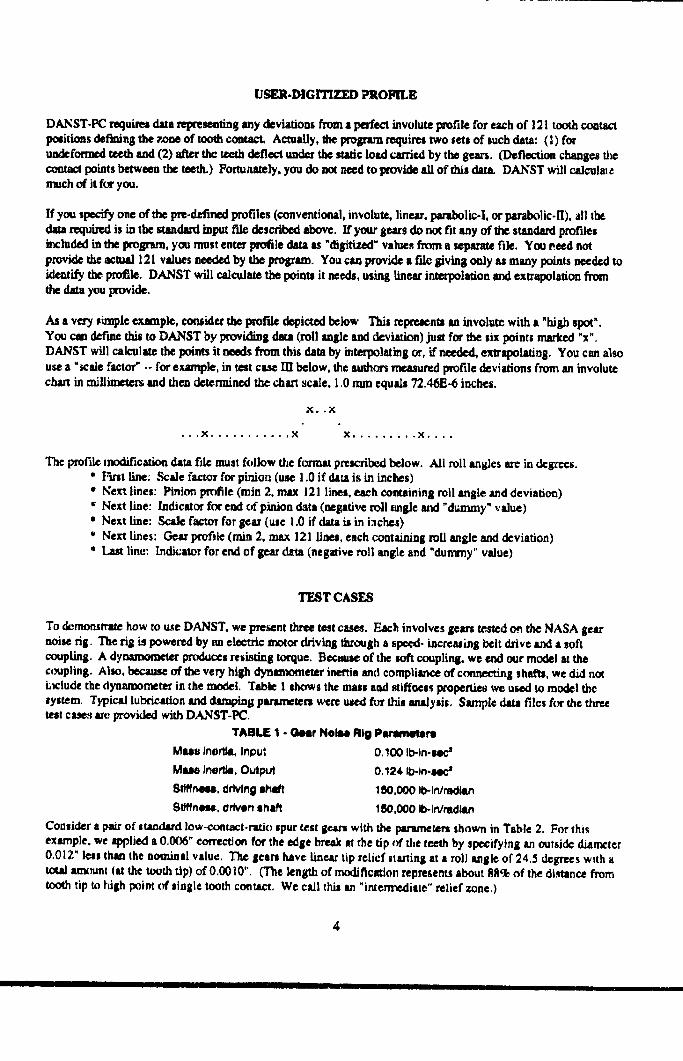
As a very _imple example, ¢omider the pmf'de depicted below This represents an involute with a "high spot".You can def'me th_ to DANST by providing data (roll angle and deviation) just for the six points marked "x".DANST will calculate the poim it needs from this data by interpolating or, if needed, exlrapolating. You ca1 also
use a "scale factor" -- for example, in test case IIl below, the authors measured profile deviations from an involutechartinm/llimetersand thendeterminedthe_trt scale,I0 nun eqmd_ 72.46E-6inches.
• , .X .......... .X X...oo,..,X.o,.
The profile modification data fdc must follow the format prescribed below. All roll anBles are in degrees.* F'tnt Line: Scale factor for pinion (use 1.0 if dJtutis in inches)
* Next lines: Pinion profile (rain 2, max 121 lines, each containing all angle and deviation)* Next lme: Indicator for end of pinion data (negative roll _ngie and "dummy" value)* Next line: Scak factor for gear (sac 1.0 if data is in inches)* Next lines: C,-earpt_efle (min 2, max 121 fine,, each containing all angle and deviation)
* Last line: Indicator for end of gear d_ta (negative roll angle and "dummy" value)
TEST CASES
To demonstrate how to use DANST, we present three t_t cases. Each involves gem teated o_ the NASA gearnoise rig. The rig is powered by nn electric motor driving through a speed- increuing belt drive and a softconpIing. A dynamometer produces resisting torque. B_ause of the soft _pling. we end our model u thec,mpling. Alto, because of the very high dynamometer inertia end compliance of connec_ng shaft=, we did noth_clude the dynamometer in the model. Table 1 shows the mass and stiffness properties we used to model thesystem. Typical lubrication and dttmping parsmetere were treed for this mudysis. Sample data files for the threetest cases tre provided with DANST-PC.
TABLE 1 - Geer Nolee Rig Parametem
Mass Inertia. Inl_ut 0.100 Ib-in-zmc*
Malw Jm_rlhl,Output 0.124 Ib-Jn-a_
Stiffness,ddvlng shaft 150,000 fO-lfl/ril_l/1
8tMn_ut, Ortvenahaft 150,000 Ib-in/radl_
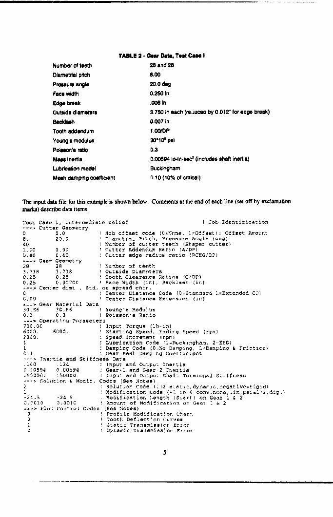
Consider a _ of standard low-contact-rati(_ spur eest gem's with the parsmetaet shown in Table 2. For thisexample, we applied a 0.006" cofre_on for the edge break at the tip of the teeth by specifying an outside d_an_tcr0.012" less than the nominal value. The gears lutve linear tip relief starting at a roll angle of 24.5 degrees with atotal ax_unt (at the toothtip) of 0.0010". (']3te kngth of modification representsabout 88% of the di._tancefromtooth tip to high point of single tooth coetact. We call this an "intermediate" relief zone.)
4
Number of teeth
DIcm_etdsJpitch
Preuum angle
Face width
Edge brtU
Outside diameters
8acldalh
Tooth addendum
Young's modulus
Poillon's ratio
Mau Iflerlla
Lubdcat_ model
Muh damping ooefflc_nt
TABLE :! - Gear Data, Test Cue I
28 and 2S
8.00
2o.o,_,_0.250 in
.006 In
3.750 in each (re,Juced by 0.012" for edge break)
0.007 in
1.00/DP
30"10' I_1
0.3
0.00594 1e-In-too' (includes ,,haft inertia)
Buckingham
n.lO (40% of c_¢ai)
The input dam fii¢ for this example i_ shown below. Comments at the end of each [ine (set off by exclamation
l]larkJ) dclc_bc da_ILitems.
Tesl; Case 1, -_ntermediate relie_-_=:- Cutter Geometry0 0.08. 20.040I.C0 1.00'0.40 C ,40=-=_> Gear Geometry28 283. 738 3, '7380.25 0,250.25 (_,0_700_=-> Cen'er diet , S_d.0
! Cob Identification
! Hob offset code (0_Nene, 1_Offset): Offset Am.ount! Di_metral Pitch, Pressure Angle (&eg)I ,_bc, r of cutter teeth (Shapez cuttez)! Cutter Addend_ Ratio {A/DP)! Cutter edge radius ratio (RCEG/Di]
! Nu:.nber of teeth! Ou:side Diameters! Teeth Clearance Ratioe (C/DP)! Face Width (in), 3acklash (in)or spread cnsr.Cen_er Distance Code (0=Standard i=Extended CD)
C.00 ! Center Distmr}ce Exter:s_en (in)_--;> Gear Material Data
30.i_6 _C.[6 _ Yeung's Medu:us0.3 _.3 ! Pois_on's _atio
-.=_> Operating Para_e:ers7OO.OC Input Torque (ib-in]6000. 6000. Starting Speed, Ending Speed (rp_.)2000. Speed Increment (rpm)1 Lubrication Code !iaBucki:,gham, 2--ZHD)1 Da_.p!ng Cede (0=No Dtlmp_ng, i-Da_.ping & _Miction}¢.i Gear Mesh Damping Coe££iclont-=-> rne:_tia and Stiffnes_ Da:a.I00 .124 _ Inpu: and Output Inertia0.30594 0.00_9_ ! Gear-i sn_ Gear-2 :norrisi_0030. 150000. ! Inp'a: and Oatpu: Shaft Torsional 5ti_nesu_=_ _oh_tlon & Moclf. Codes (See Notes)2i-24.5 -24.5O.CCI0 0.O01C==-> Plo: ConTro_ Cod(:n3
10
Solu:_on Code (i12 s:;atic,dynaric,negative:rig_d)Modificatio_ Code (-i to ¢ conv,nc)no,.in,pa;¢i/2,dlg.)Modification Length {S_ert) on Gea: i & 2_otur.t of Modlf_cation on Gear i & 2
(See Notes)! Profile Medlfica:_on Char::! Tooth Defiect_on curves! S=atic Transmission Error! Dynamic T_ane_ss!o_ Error
oI0000000
_:=>?:inter-Plot Outpu: Device Code0 ! O--VGA, I_EPSON FX-8*0 2=HP LJ,
Static Tooth LoadDynamic & S=a:ic _ooth LoadStatic Tooth S_iffneeaFFT of Static Drana_iseion ErrorFFT of Dyr.a_ic Too:h LoadFriction Coefficienu
Frictiol; TorqueDyna:r.ic SZressDynamic Fac:or Speed Survey
3=Poet Sc:zip_ _ile, 4=Auto CAD File
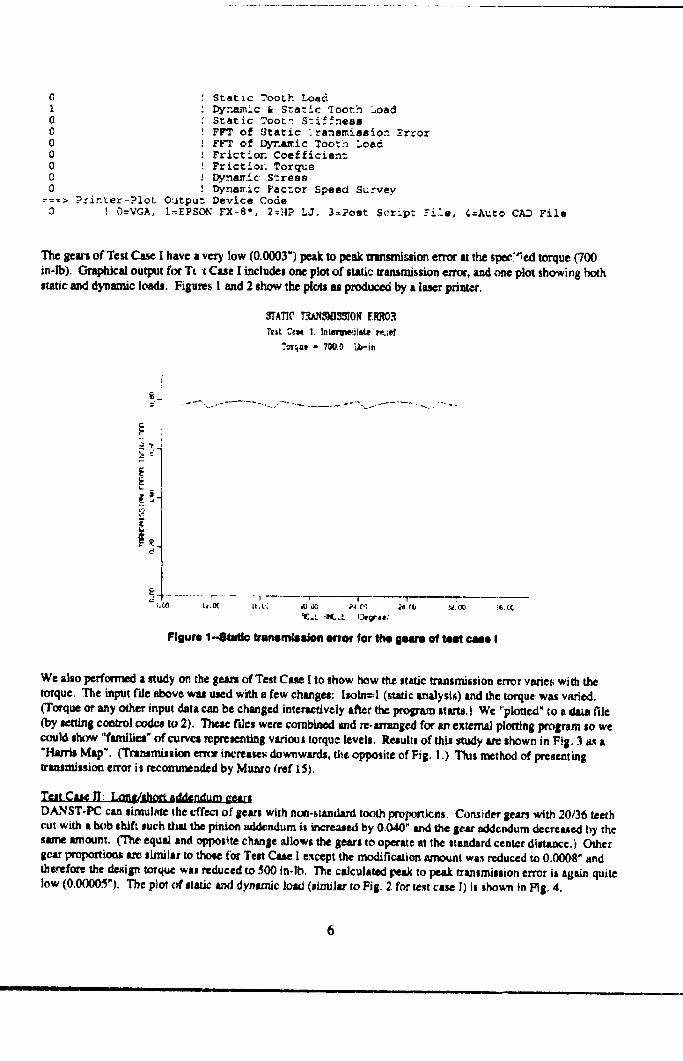
The gears of Test Case I have a very low (0.0003") peak to peak minsmission error at the apec_'_ed torque (700
in-lb). Graphical output for T_ -t Cue I includes one plot of static transmission enor, a,d one plot showirlg both
static and dynamic loads. Figures I and 2 show the plots as prodtx:ed by a laser printer.
_ATIC T'._AN3)/]_510NENR¢._
Test C_N I. Int,m'l.e]imLe r_.:ef
.'oT_ue- 7_,0 i2}-in
I
[:.... f ....... 1 F 1 r'i._ tc,OC it,t'; 10, _iO ti,_ _I. Cl,_ _iClO _i.tC
Figure 1-81 Vinimlnln error for t_ IHrl of IK ¢ll I
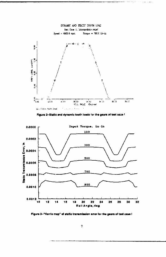
We also performed I study on the gears of Test Case [ to show how the italic transmiisio, error varie_ with the
torque. The input f'de above was used with a few changes: l,oln=! (sic analysis) tnd the torque was varied.
(Torque or any other input data can be changed interm:tively after the program starts.) Wc "plotted" IO a / file
(by le.ttini controlc'od_ to 2). TI_ ides were combined and re.arrangedforan externalploaing program so we
could|slum,"families"of curves rcpn:_ent_nllvarioustorquelevels.Resultsof thlsstudy areshown in F.tg.3 a.,ta
"l-hu'risMap". (Transmission enx_ increasesdownwards, t_e opposi:e of Fig.I.) This method of presenting
transmissionerroritreeonunended by Munro ¢ref15).
rs,at_C,ttt_ul,m_/Jthm_dd__
DANST-PC can simulnte the effect of getri with non-tumdard tooth propo_icns. Consider ilears with 20/36 teeth
cut with a h_)b shift such Oust the pinion mldendum it incremeed by 0.040" and the gem" addendum clecre_ed by the
same itmoun(. ('The equal and opposite ehanle allows the gem's to operate at the standard center distance.) Othergear propoftionl are limill; to thoee for Test Case I except the modification amens wis reduced to 0.0008" and
therefore the deaiiln t_rquc was reduced to 500 in-lb. The calculated peak to peak transmission error it again quite
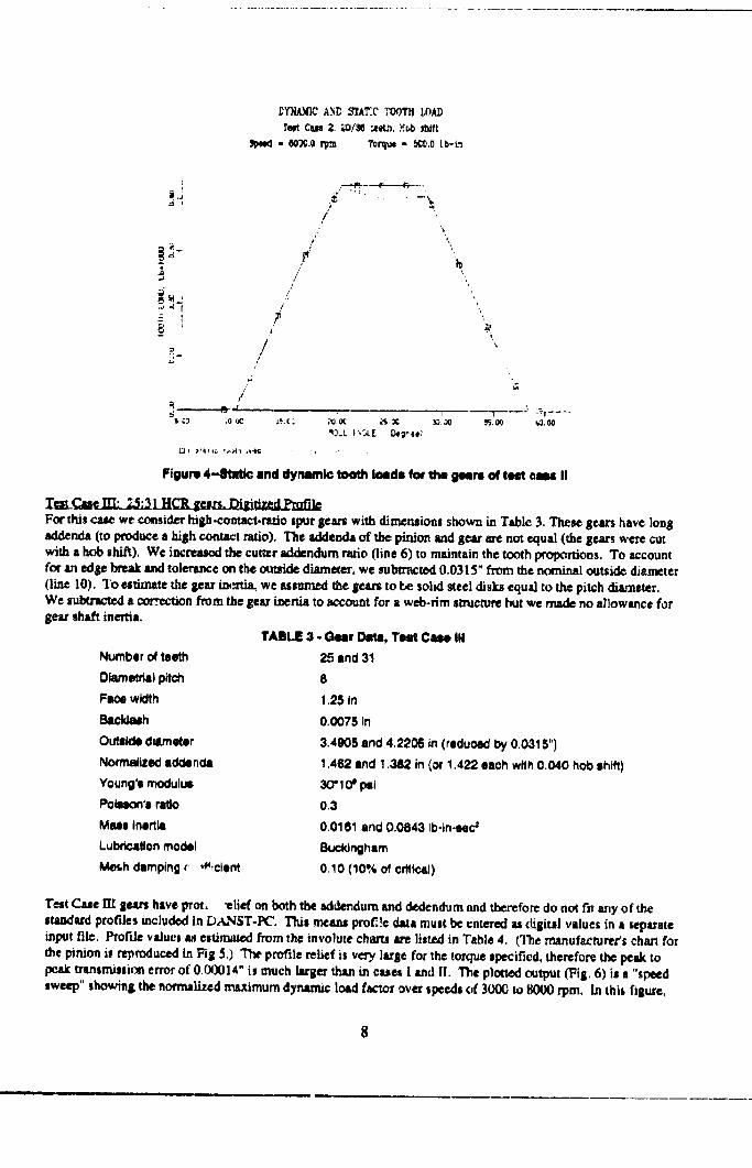
low (0.00005"). The plm of staticand dynamic load(similarto Fig.2 for te_tcase l)Isshown inFig.4.
II I I l l ., ,,. ,
_¥'nIA_il(_ ,_.N_ _A,_C' TOOTH LOA_
T.- cmN 1, ",Lermc_a_e re_
_peed = _000+0rl_. Tc_ue - "_:.C Lb-L_
D
7
2
, °- _'-T
...... _-. _;, -_ ,
S "• _'"X
,\/
/ t
/ \
u 1" v
%_.L _CL[ (DeCrial
Rgure 2-Static _d dynamic tooth loads for the geam of rut cs3e !
0.0000
0.0002
_" 0.0004ua
0.0006
u 0_006
jlfJ
0.0010
0,0012
Znpttt e_O_Cl_e, :_n-lb
IO0
500
?00 _
_____ , £ . • . £ + L . a . I,, - J * _ • £. - I
0 12 14 18 18 20 22 24 20 28 30 32
Roll Angle, dill
figure 3--"Hlrrls rasp" of ete_o trsnemleelon error for the gears o4 test _ I
- IOX.Oriyal Toi'gl_x- _0.0 Lb-k-_
-: I T
o /
/
/
/'
/
//
/'
/
'%
b
,'-.o._ _.x _oI_ _--":" _ ....P;.O0 _,00
Figure 4-81M_ and dymimi© tooth loads/or the gears of test 0m II
Zes_ _:31 HCR_es_ill_d..ymfj_
For this case we c.omider high-contacl.rabo spur i_u's with dimensions shown in T•ble 3, These gears have long
sddende (to producea high _1 ratio). The addenctl of the pinion _ gear_ not _ual (the sears wen: cutwith a hob shift). We increased the cunrr sdd_ndurnr_tio (line 6) to maintainthe tooth proportions. To accountfor an ,_l_e br¢_ _undtolerate cc the outside diarn_er, we sulm-acted0.0315" from the nominal outside diameter
(line 10). To estimate the gear i_ia, we assumed the gem to be sold steel disks equal to the pitch cliartm_r.We su_ a cor.n-.ctionfrom lee gear inerti_to account for a web-rim smacturebut we made no al]owance forgear sha.ft inertia.
Number o_ teeth
Diammrial pitch
Fa_ewidth
Band_h
Ou_lido dillmotor
Normalized 8tldond_
Young's modulus
Patroon'- ratio
Muo inortl_
Lubrtcdon model
IVl_,h damping _" ,_iclont
TABLE 3 • Out DI_, Test Cue III
25 end 31
8
125 In
0.0075 _n
3,4005 and 4.2206 in (roduoed _ 0,0315")
! .462 end 1.382 in (_w 1.422 nob with 0.040 hob sh_)
30"_ Cf _i
0.3
0.0161 end 0.0843 Ib-tn-_ec _
Buckingham
0.10 (10% O_orl_cltl)
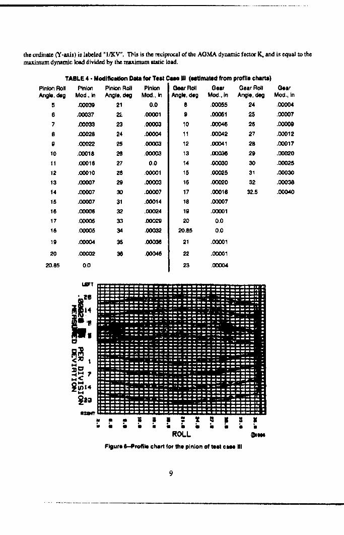
Test Case I_ gears have pro/, "elief on bo_h the addendum and dexiendum ,rod therefore do not fear, y of the
standard profiles included in DA_$T-PC. This rneitms pro£!c diua must be entered as digiul values in • separateinput flit. Profile v_dues as estimaw0 from the involute charts are listed in Table 4. (']'he manufacturer's chart for
the pinion i_ reproduced in _ig 5.) The profile relief is very larle for the w_./ue specified, therefor_ the peak to
l_sk u'snsnussion error of 0.00014" is much larger slum in cues 1 and I1. The plotled output (Fig. 6) is s "speed
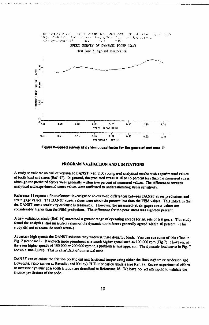
sweep" sho,,vin$ the normalized maximum dyrutmic load f_cu_r ove_ speeds of 3000 to 8000 rpm. In this figure,
the ordinal¢ Cl'-axis) is labeled "I/KV", This is the reciprocal of th©AG,_L_ dynamic factor K_ and is equal to the
maximum dynamic load divided by the maximum static load.
TABLE 4 - Modlfic04Jon Data for Test Case Ul (Ntimatod from profile chwts)
Plnior_Roll Pinion Pinion Roll Pinion
Angle, cleg Mod, in Angle, deg Mod., in
5 .00039 21 0,0
6 .00037 2_ ,00001
7 .0O0'33 23 .0OOO3
8 .00028 24 ,00004
0 ,00022 25 ,00003
10 .00018 26 .O(X)03
11 .00016 27 0.0
12 .00010 28 ,0o001
13 .(X)OO7 29 .00003
14 .00007 30 .00007
15 .00007 31 .00014
16 .(X)O06 32 .00024
17 .00005 33 .00029
18 .00005 34 .00032
10 .00004 35 ,000_
20 .00C02 36 ,00046
20.85 O0
Gear Roll Gear
Angle, deg Mod., in
8 ,00055
9 .00051
10 .00046
11 .00042
12 .00041
13 .00036
14 ,00030
15 .00025
16 .00020
17 .00016
18 .00007
19 .00001
20 0.0
20,85 0.0
21 ,00001
22 .00001
23 .00004
Gear Roll Gear
Angle, deg Mod., In
24 .00004
25 .00007
26 .00000
27 .00012
28 .00017
29 .00020
30 .00025
31 .00030
32 .00038
32.5 .00040
I.UI
< t
," " = F s .'J 2 _= II = I• b b ., :- ;, b " • _= b
ROLL _m
Figure 6--Prc411echart for the pinion of test ¢m Iil
9
_f".. _'q-i-:: : :_,_ _ :' _._," 't" .""._Ygr.' _U: ,; ._Jt,_, .,"._:'C _. r.,'l- • '.1 : " _"
_FEED 3_JEV_:YOF DYNAMIC TOOTI_LOAD
TestC_e 3,ci_,i_izedmodd:c_t_.cn
I,
o
i"
1 _ T T - T
I I J _ T T ! -
_.41 r..5l 0.[sl _. 72 O.e2 0._ I.
_EFf_M_NC_ _P[_.D
Figure 6--$pe_d survW of dynmmlc load f_tor for the 9Nrm oftm_tmmm$ III
PROGRAM VALIDATION AND LIMITATIONS
A study Io validate an earlier version of DANST (ver. 2.00) compm-ed analytical resul_ with experimental valuesof tooth load and stress CRef. I?). In gereral, the predicu_d _ress is 10to 15 percent less than the measurc, d stressalthough the predicted fo_c=s were geaendly within five i_e_nt of measured value. The differences betweenanalylical and e:tperin_-ntal stress values were atu'/_ to underestimatingstress sensitivity.
Reference 13 repom a l'mite element investigation ;o examine differences between DANST stress predic_ons andswain gage values. The DANST s'_ess values were about six percent leas than the FEM values, This indicates thatthe DA_ST stm, sensitivity estimate is _ablc. However. the measured (stntm gage)so'=ssvalues arc
considerably higher than the FEM predictions. The diff..nee for The peak sn'e_ was eighteen percent.
A new validatiot_s_udy(Ref.14)examineda greaterrangeofoperatingspeedsforsixsetsoftestgears.Thisstudy
found the ,mal_cal and measured values of the dynamic tooth forces generally agreed within lO percent. Clhismudy did not evtluatc the tt_thstress.)
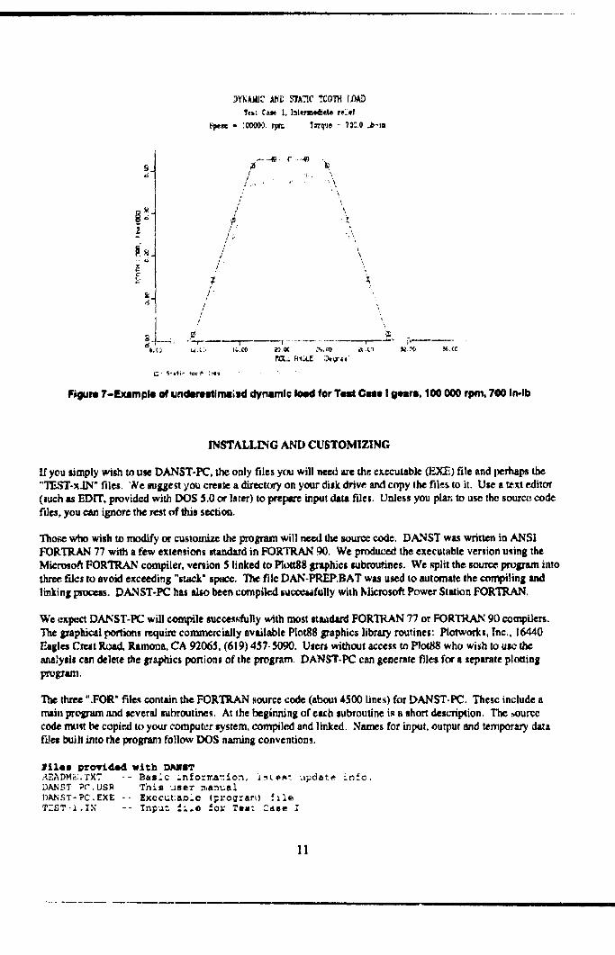
AtcerutinhighspeetLt'.heDANST solutionmay undercstitrmtedynamic loads. You canse_son_ ofthiseffectin
Fig.2 (testcaseI).Itismuch more prominentata much higherspeedsuchas I00000 rpm (Fig7), However.at
the even higherspeeds of I_0 000 or 200 000 rpm this problem is less apparent. The dynamic load curve in Fig. 7shows a small jump. This is an m'tifact of numerical error.
DANST can calculate the friction coefficient and frictional torque using either the Buckingham or Anderson andLowcnth_ {alsoknown asBenedictand Kelley)EI-rDlubricationmodels(seeRef,3),Recentexperimentalefforts
tomeasuredynamicgeartoothfrictioneu_edescribedinRcfcrcncc16. We havenotyetattemptedtovalidatethefrictionpro_ictionaofthecode.
10
Teb: C_ !. I_t_m_et* .Llf
Fp.c - 10000.)._ 'fm'q'_e_: 7_.0 _-tn
2
2
e;"
/
¢'
/
/.; °-
/
1
3¸/"1
/i
/
t,_._. :, IG.O0
i
• r
"r't
\
_ r,..--_ _,--_d
6.() L_.X ..%.O0 _._ _.,'_ N..(C
Figure 7-_(lmple of uncleretdlnm_sd dynamic Ioed for Teat Cue I gq.trs, 100 000 rpm. 700 In-lb
INSTALLLNG AND CUSTOMIZING
If you simply wish to use DANST-PC. the only files y(sJ will need are the executable (ESZ) file and perhaps the
"TEST-x.I_" files. 'Ne smggest you create a direcur:y on your disk drive and copy the fil.es [o it. Use s _xt editor
(such as EDIT, provided with DOS 5.0 or later) to prepare input data files. Unless you plan to use the source, code
fdes, you can ignore the rest of this section.
Those who wish to modify or customize the program will need the urar_e cod_. DANST was writ'ten in ANSI
FORTRAN 77 with a few extensions standard in FORTRAN 90. We produced the executable version using the
Micrmo_ FORTRAN compiler. ,_e, ion 5 linked to Plott88 graphics _broutines. We split the source, prt_ram into
three fdcs to avoid exceeding "sta_k" spe_e. The file DAN-PREP.BAT was u_e.,d to automate the compiling and
linking pmca_s. DANST-P_ has also been compiled su_c4_fully with _Iicro_ Power Station FORTRAN.
We expect DANST-PC will cempile succe_dully with most studard FORTRAN 77 or FORTRAN 90 mmpiders.The graphical portions require commercially available PlotS8 _'aphics library routines: Plotwotks, Inc., 16440F.agles Ct_Jt Road. Ramona. CA 92065, (619) 457-5090. Users without a_cess to Plot88 who wish to u_ the
analysi_ can delete the graphics portions of the program. DANST.P_ can generate files for s separate ploUingprolp'sm.
The threa ".FOR" files contain the FORTRAN source code (about 4500 lines) for DANST-PC. Thcsc include a
mai, prc_am and _everal _ubroutine._. At the beginning of cub subroutine i_ a short desc_ption. The _urce
code must be copir, d to your computer _ystem, compiled and linked. Names for input, ou_ut and temporary data
files built into the program follow DOS naming conventions,
_£1es _rov£_wXCh DANII_
DAN_T Pc_.USE This use_ manualDANST-PC.EXE -- Executaoie (_ro_:a_,) _leT_ST-2.1X -- Tn_u: _i*O fO_ Te8: Case I
II
TES?-2. "_N --T_S?-3. -N --TEST- 3.MOD --DAN- ?R_. BA_.--DANST- PC.FOR --DA/_ST-2 .FOR -oDANST- 3 .FOR --
Input file for Tee: case iiInput file for Tes: Case =IIDigitized profile cla:a for Tes:Used to compile and linkSource code No. 1Source code No. 2Source code No. 3
Ca_e III
REFERENCES
t Lee, C, Lie, H.H., Oswald" t'.B., and Townsend, D.P., 1991, "Influence of Linear Profile Modification and
Loadini; Conditions on the Dymunic Tooth Load and StrcsJ of High Contact Ratio Gears." J. of Mech. Design. Vol113, No. 4, (NASA-TM- 103136).
2 Lin, H.H., and Huston, R.L., 1986, "Dynamic Loading ¢qnParallel Shaf_ C_.ar,," _ASA CR-179473
3 Lin, H.H., Huston, R.L., and Coy. JJ., 1988. "On Dynamic Loads in Parallel Shaft Transmissions: Part I -
Modeling and Analysis," AS.ME Trans., I. of Mechaaisms, Transm. and Automation in Design, Vol. 110, No. 2,
pp. 221-225 (NASA-TM-100IS0).
4 Lin, H.H., Huston, RL., and Coy, JJ., 1988, "On Dynamic Loads in Parallel Shaft Tntr_rniuio_: Part II -
Parameter Study," AS,ME Trans., J. of Mechanisms, T'tan_n. and Automation ia Design, Vol. 110, No. 2, pp.226-229, (NASA-TM- 100181).
5 Lm, H.H., Townsend, D P., andOswald, F.B., 1989, "Dynamic Loading of Spur Gears with Lineer or ParabolicTooth Prorde Modifications," Proc. of ASME 5th Int. Power Trans. and Gearing Conf., Chicago, IL, Vo]. l, pp.409-419 ('NASA TM. 101444).
6 Lin, H.H., Oswald, F.B., and Towmend" D.P., 1988, "Profile Modification to Minimize Spur Gear Dynamic
Loading," NAS A-'T'M-8990 !
7 IAn, H.H., lee, C., Oswald, F.B., Townsend, D.P., 1993, "Computer-Aided Design of High-Contact-Ratio Gearsfor Minimum Dynamic Load and Stress," J. of Mech. Design, _o1 _|5. No. 1, (NASA-TM- 103275).
8 Lin, H.H., Wang, J., Oswtld, F.B., Coy, .r.j., 1993, "Effect of Extended Tooth Contact on the Modeling of Spur
Gear Transnrussiost_", AIA.A PAPER 93-2148, (NASA-TM- 106174)
9 Lin, H.H., Oswald, F.B., Townsend, D.P., 1996, "Balancing Dynamic Strength of Spur C,eart Operated atExtended Center Distance", to be presented at ASME 7th Int. Power Trans. and Gearing Conf., San Diego, CA,(NASA.TM. 10"7222)
10 IAou, C-H., Lin, H.IL, Oswald, F.B., Townsend, D.P., 1992. "Effect of Con_cr Ratio on Spur Gear DynamicLoad," Proc. of AS.ME 6th Inl. Pr_wer Trans. and Gearing Conf., Phoenix, AZ, VoI. 1, pp. 29-33 (NASATM- 105606).
I 1 Liou, C-H, Lin, H.H., Oswald, F.B., Townsend, D.P., 1993, "Using Hob Offset to Balance Dynamic Serength inSpur Gears," AIAA PAPER 95-3046, (NASA-TM- 106934)
12 Oswald, F.B., Rebbecht, B.. Ztkrljsek, JJ., Townsend, D.P., and Lin, H.H., 1991. "Comparilon of Analysl_and Experiment for Dyna,nrfict of Low-Contnct-Ratio Spur Gears," ASME 13th Bienni_d Conf. on MechanicalVibration and Noise, Miami, FL, (NASA TM- 103232).
13 Oswald,F.B.,l.ln,H.II.,Liou,C-H.,and Valco,M.J.,1993,"Dynamic AnalysisofSpurO_rs Using
Computer Program DANST," AIAA 93-2295,(NASA TM-I0621 l).
12
14 Oswald, F.B., Townsend, D.P.. Rcbhcchi, B.. and Lin. H.H.. ]996. "Dynamic Forces in SpurOears..Me&_rement, Prediction, and Code Validation," to be presented at ASME 7th Int. Power Trans. and
Gearing Conf., San Diego, CA, (NASA TM-107223).
15 Munro, R.G., 1989, "The D.C. Component of Gear Transmission Error", Proc. of ASME 5th Int. Power Trans.
and Gearing Conf., Chicago, IL, Vol. 1, pp. 467-470
16 Rebbechi, B., Oswald, F.B., and Townsend, D.P., 1996, "Mea_rernent of Gear To_xh Dynamic Friction," to be
presented at AS.ME 7th Int. Power Trans. and Gearing Conf., Saa Diego, CA, (NASA TM. 107279).
13
1. _ u_lsONLY(Lm.,_
4. 1111.EANDIKJ_TITL!
2. REPoRIr DAI"!
August 1996i
Dynamic Analyms of Spur Gear Tnu_m/mions (DANST)PC Vcnda_ 3.00 U_r Mm_ua]
i, ma_4om_
Fred B. Oswtkl, Hsiang Hsi lJn, and Ireben R. Delgado
NASA Lcwb Rematch Ccnte_
C_llml, Ohio 44135--3t91
mid
vd_cle PropulsioeU.S Armyaesem_hLat_me_C_eveilm_. Ohio 44135-3191
o, m_mOmN_Og4rrom0_ Aan_ NAkW._)_ _eml(_)
N_a_i Aeme_ic_ andSpac_Azln_Wmd6agml,D.C 2_ulK-J.4_1lad
U.S, Army _h _-,¢_y
s. n_wr-rt_ mm OAV_ COV_._
Technical Memorandum
_I.ImUNDING NU_IIER8
WU-505-62-361L162211A47A
m,e_kom_.o _w_um.m.'
lO. BImON(_INQ_ O_ITO_IN_II*ORT NUMIIER
NASA TM-107291ARI_TR-II89
11. IUPIq._M_NT_Id_f
Fred B. Cmvald, NASA Lewis Re._eatch Center: Hsiang HsJ l.in, Umversity of Memphis, Memphis, Tennessee 38152; andIreben R. Delgado, Vehicle Propulsion Directorate, U.S. Army Re_asch I.a_boratory,Lewis Research Center. Responsibleperson, Fred B. Oswald, organization code 2730, (216) 433-3957,
lla. DImlIUTK_AVAIAIIIJT'V IrrATll_l_
Unclassified - Unlimited
Sub)cot Calzgory 37
"['hit pablJcttion is avtiltbk: from _c NASA C_t= for Aero,¢;p_c Information, (301) 621-03f_.
12b. DW'fl_N COGE
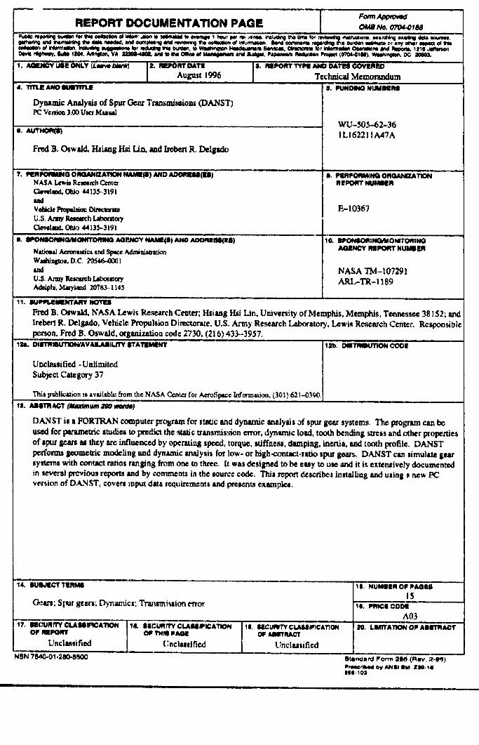
DANST is a FORTRAN computer pro&ramfor ttaUc t_d dynamic enaJysi$ of mpur gear systems, The prolFItm can beused for ptrametric studies to predict the ,_tatic_'tnsmission error, dynamic load, tooth bending stress and other propertiesof spur gean u they arc influenced by operating speed, torquc, _ffnesg, damping, inertia, and tooth profile. DANST
perfonm geomelri¢ modeling and dynamic malysis for low- or high-contact.r_o spur gears. DANST can nimulate gearsystems with co.tact r_os ranging from oae m three. It w_ designed to be easy to use and it i._extensively documentedinseveralprevioasreports_md by comments inthesourcecode,Th/sreportdescribesinstallingand usingmnew PC
version of DANST, coven input data requirements and pretent_ exampl_.
14. IlOIIkn_T 'l'lLa_,qg
Gown; Spur 8_art, Dynamics.Trtrunni_ion t,_vor
Unclassified _;nclasmlfied
_s_ 7uo.o_.=_
le, II_CURr_r C tJUMllrlCATION
Unclaszificd
_s..u.sm. o, _,3u15
k'o.mcmcornA03
StanOa_l Po_ ;le8 (R_n,, _-_9)
ItlO.l_
im ,,