dvf 5000 - justrising.com
TRANSCRIPT

DVF 5000Compact, Simultaneous5-Axis Machine forHigh-Speed Multitasking

DVF 5000The new Doosan DVF 5000 5 axis machining center provides world class productivity and reliability for simultaneous 5 axis machining operations. It’s stable structure and compact footprint is ideal for production of small to medium size workpieces with complex shapes. The DVF5000 also includes an eco-friendly all-grease lubrication system.
Product Preview
Basic information
Basic Structure
Cutting
Performance
Detailed
Information
Options
Applications
Diagrams
Specifications
Customer Support
Service
DVF 5000

02 / 03
Contents
02 Product Overview
Basic Information
04 Basic Structure
07 Cutting Performance
Detailed Information
08 Standard / Optional Specifications
10 Applications
12 Diagrams
15 Machine / CNC Specifications
18 Customer Support Service
High productivity & speed Simultaneous
5-Axis Machine
12000 / 18000 r/min high speed spindle
Ø500 mm (19.7 inch) 2-axis tilting table (option : Ø630mm (Ø24.8 inch))
- Max. workpiece weight 400kg (881.8 lb)
User friendly machine
Compact footprint Grease lubrication system Easy operator access to machine Compact automation system (AWC)
High precision function
Spindle & Structure Thermal Compensation Spindle Cooling Standard (Option : ballscrew shaft cooling system)

Provides high rigidity and easy operator access.
We provide stablemachining performancewith high speed directand built-in spindle.
Machine configuration
Spindle
Travel distance
X axis 625 mm
Y axis 450 mm
Z axis 400 mm
Rapid traverse
X axis 40 m/min
Y axis 40 m/min
Z axis 40 m/min
Product Preview
Basic information
Basic Structure
Cutting
Performance
Detailed
Information
Options
Applications
Diagrams
Specifications
Customer Support
Service
X-axis
(24.6 inch)
(17.7 inch)
(1574.8 ipm)
(1574.8 ipm)
(1574.8 ipm)
(15.7 inch)
Z -a
xis
B -axis
C -axis : ±360
-30 ~ + 110
Y -axis
Fanuc
12000 r/min
18.5 kW /118 N·m
18000 r/min
22 kW /118 N·m
HEIDENHAIN
12000 r/min
17 kW /109 N·m
18000 r/min
30 kW/155 N·m
(24.8 Hp / 87.1 ft-lbs)
(22.8 Hp / 80.4 ft-lbs)
(29.5 Hp / 87.1 ft-lbs)
(40.2 Hp / 114.4 ft-lbs)
DVF 5000

04 / 05
Provides stable machining performance with a wide machining area and trunnion support option.
Table
Servo tool magazine as standard for high productivity and reliability.
Tool MagazineServo Magazine
30 ea (40/60/90/120 ea)
Tool to Tool
1.3 sec
Trunnion support
H 4
50 m
m (H
17 .
7 in
ch)
ø 550 mm (ø 21.7 inch)
Table size
ø 500 x 450 mm
ø 630 x 450 mm
Max. workpiece size
ø 550 x h 450 mm
Max. Work load
400 kg
(with trunnion support)
(881.8 lb)
(ø 19.7 x 17.7 inch)
(ø 24.8 x 17.7 inch)
(ø 21.7 x 17.7 inch)
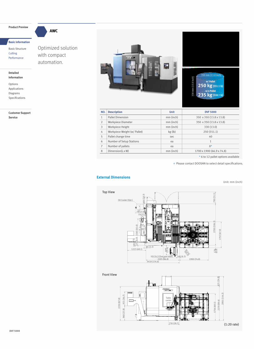
AWC
External Dimensions
Optimized solution with compact automation.
NO. Description Unit DVF 5000
1 Pallet Dimension mm (inch) 350 x 350 (13.8 x 13.8)
2 Workpiece Diameter mm (inch) 350 x 350 (13.8 x 13.8)
3 Workpiece Height mm (inch) 330 (13.0)
4 Workpiece Weight (w/ Pallet) kg (lb) 250 (551.1)
5 Pallet change time sec 40
6 Number of Setup Stations ea 1
7 Number of pallets ea 8*
8 Dimension(L x W) mm (inch) 1700 x 1900 (66.9 x 74.8)
Top View
(1:20 rate)
Front View
330
mm
(13 .
0 in
ch) 350 mm (13.8 inch)
250 kg (551.1 lb)
(518.1 lb)235 kg
Unit: mm (inch)
Oil Cooler (Opt.)
464
(18.
3)
1565
(61.
6)18
5 (7
.3)
1223 (48.1)
920 (36.2) (Door open width) 160 (6.3)
3418 (134.6)2205 (86.8) 1900 (74.8)
1702
(67.
0)
176
(6.9
)63
1 (2
4.8)
2270
(89.
4)
1756
(69.
1)
2230
(87.
8)
960
(37.
8)93
1 (3
6.7)
Table center
730 (28.7)
2901
(114
.2)
2700
(106
.3)
790
(31.
1)
R1147
(45.2)
85 (3.3)
175
(6.9
)
646
(25.
4)
708 (27.9)334 (13.1)
455 (17.9)
Product Preview
Basic information
Basic Structure
Cutting
Performance
Detailed
Information
Options
Applications
Diagrams
Specifications
Customer Support
Service
w/ Pallet
w/o Pallet
* 6 to 12 pallet options available
* Please contact DOOSAN to select detail specifications.
DVF 5000

06 / 07
Machining Examples
Ball Bar Measurement Test
Higher roundness accuracy is realized by the advanced design of machine structure and Doosan control system.
X-Y Plane
Roundness
3.8 ㎛Feedrate
4000mm/min
+Y
+X
Machining Performance
Max. chip throughput
Item Material (SM45C) Condition
Machining removal rate 599 cm3/min (36.6 inch3/min)
Ø80mm (3.15 in.)Face Mill (6Z)
feedrate 4680 mm/min (184.3 ipm)
depth of cut 2 mm (0.1 inch)
Item Material (AL6061) Condition
Machining removal rate 1814 cm3/min (110.7 inch3/min)
Ø80mm (3.15 in.)Face Mill (6Z)
feedrate 9450 mm/min (372.0 ipm)
depth of cut 3 mm (0.1 inch)
Item Door Handle (Aerospace)
Material Aluminum
Cycle time 3 hour 30 min
Tool Ø12 (0.5) x R2 Endmill
Spindle speed 8000 r/min
Feed rate 1800 mm/min (70.9 ipm)
* The results, indicated in this catalogue are provides as example. They may not be obtained due to differences in cutting conditions and environmental conditions during measurement.
From high speed machining to heavy duty cutting, diverse machining operations are possible for a wide variety of complex workpiece shapes.
Cutting Performance
(157.5 ipm)

08 /
Standard / OptionalSpecifications
Various optional featuresare available to satisfycustomers’ specificmachining applications.
NO. Description Features DVF 5000
1Spindle
12000 r/min ●
2 18000 r/min ◦
3Magazin Tool storage capacity
30ea ●
4 40 / 60 / 90 / 120ea ◦
5Tool shank type
BIG PLUS BT40 ●
6 CAT40 / DIN / HSK A63 ◦
7
Coolant
FLOOD 1.1 KW_0.7 MPA_30 L/MIN ●
8
TSC
None ●
9 1.5 KW_2.0 MPA_BUILT-IN FILTER ◦
10 2.2 KW_3.0 MPA_BUILT-IN FILTER ◦
11 3.7 KW_7.0 MPA_BUILT-IN FILTER ◦
12OIL SKIMMER
None ●
13 BELT TYPE ◦
14
Chip disposal
Chip conveyorCHIP PAN ●
15 HINGED BELT_LEFT SIDE ◦
16Chip bucket
Folklift type ◦
17 Rotation type ◦
18 Air gun ◦
19 Coolant gun ◦
20Precision
machining
options
Linear scale X / Y / Z axis ◦
21
Measurement &
Automation
IKC Receiver
NONE ●
22 RENISHAW (RMI-Q) ◦
23 HEIDENHAIN (SE660) ◦
24 BLUM (RC66) ◦
25DATUM BALL FOR IKC
NONE ●
26 DATUM BALL_D25 ◦
27
TOUCH PROBE FOR IKC
NONE ●
28 RMP60_RENISHAW ◦
29 TS460_HEIDENHAIN ◦
30 TC60_BLUM ◦
31
Automatic tool
measurement
NONE ●
32 TS27R_RENISHAW ◦
33 RTS_RENISHAW ◦
34 NC4_RENISHAW ◦
35 TT160_HEIDENHAIN ◦
36 ZX SPEED_BLUM ◦
37
Others
LED Work light ●
38 3 Color signal tower ●
39 Tool load monitoring ●
40 EZ Guide i ◦
41 Automatic power off ●
● Standard ◦ Optional X Not applicable
* Please contact DOOSAN to select detail specifications.
Product Preview
Basic information
Basic Structure
Cutting
Performance
Detailed
Information
Options
Applications
Diagrams
Specifications
Customer Support
Service
DVF 5000

0908 /
* When using Tool Length Measurement, contact Doosan for detailed capacity diagram
Peripheral Equipment
Intelligent Kinematic Compensation for 5-axis Recommended Option
For high accuracy 5 axis machining, Intelligent Kinematic Compensation function is recommended. This function minimizes error in complex 5 axis machining applications by
maintaining the tool point in the correct position relative to the workpiece. In order to use this function, the following optional items are required.
Tool length measuring
Maximum workpiece limit
Limited use of Max workpiece
Non Limited use of Max workpiece
Recommended optional items
1. Software
2. Receiver 3. Touch Probe 4. Datum ball
FANUC NC: DCP-i (Developed by DOOSAN) Heidenhain NC: Kinematic opt
Renishaw(TS27R)
Renishaw(NC4S)
Heidenhain (TT160) Blum (ZX Speed)
Automatic tool breakage detection (Touch type)
Ø550 x 240 mm
Automatic tool breakage detection (Laser type / Rotating touch type)
Ø550 x 450 mm
(21.7 x 9.4 inch)
(21.7 x 17.7inch)

1110 /
Convenient Operation FANUC
15 inch
10.4 inch
Convenient and intuitive User interface.
Description HEIDENHAIN Remarks
Screen size 15” STD -
Storage memory 21GB STD -
Interference prevention system
Optional -
Kinematic OPT. OptionalMeasuring
device not included
Look-ahead block 1024 blocks -
3D line graphics Std. -
15" LCD
15 inch
HEIDENHAIN
Superior Hardware Specifications
15” LCD and large capacity 21GB memory
Product Preview
Basic information
Basic Structure
Cutting
Performance
Detailed
Information
Options
Applications
Diagrams
Specifications
Customer Support
Service Designed for user convenience
Convenient and intuitive UI
Optimized button size
High-visibility lamps
Long lifecycle buttons
Partitioned to prevent operator error
Convenient option buttons
Detachable buttons
Spare I/O signal ports for optional devices
Customized functionality
Customer-specific function switches
Available for auxiliary panel design
Design optimized for customers' needs based on extensive know-how
Large 15inch screen display
User-Friendly Operation Panel
Large 15inch screen and user-friendly operating function ensure convenient and efficient operation.
DVF 5000

1110 /
Easy Operation Package (EOP)Setting up of tools, work pieces and programs, as well as troubleshooting for abnormal condition of main machine elements is designed to minimize waiting time, maximize operational efficiency, and enhance operator convenience.
Adaptive Feed Control (AFC)Function to control feedrate so that the cutting can be carried out at a constant load(To adapt to the spindle load set up with constant load feedrate control function)
Tool ManagementFunction to manage tool information[Tool information] - Tool No. - Tool condition : normal, large diameter, worn/damaged,
used for the first time, manual - Tool name
Tool Load MonitorFunction to automatically monitor tool load(Different loads can be set for one tool according to M700 ~ M704)
Pattern Cycle (Engraving funtion : )Function to create frequently-used cutting programs automatically - Pattern Cycle: creates a program for a pre-defined shape - Engraving: creates a program for cutting a shape described
with characters (option)
Work Offset SettingFunction to configure various work offset settings
Alarm GuidanceFunction to show detailed info on frequently triggered alarms and recommended actions
Sensor Status MonitorFunction to view sensor conditions of the machine
ATC RecoveryFunction to view detailed info with recommended actions and to perform step-by-step operation manually(when an alarm is triggered during an ATC operation)
The software developed byDoosan's own technologyprovides numerousfunctions designed forconvenient operation.
Easy Operation Package

1312 /
Power-Torque Diagram
FANUC
HEIDENHAIN
12000r/min Direct 18000r/min Built-in
12000r/min Direct 18000r/min Built-in
Speed Speed
Speed Speed
Power
Torque
Power
Torque
Power
Torque
Power
Torque
12000 r/min 18000 r/min
12000 r/min 18000 r/min
18.5/11 kW
118 N·m
22/18.5 kW
118 N·m
17/10 kW
109 N·m
30/24 kW
155 N·m
Spindle speed : r/min Spindle speed : r/min
Spindle speed : r/min Spindle speed : r/min
Pow
er :
kW (H
p)
Pow
er :
kW (H
p)
Pow
er :
kW (H
p)
Pow
er :
kW (H
p)
Torq
ue :
N·m
(ft-
lbs)
Torq
ue :
N·m
(ft-
lbs)
Torq
ue :
N·m
(ft-
lbs)
Torq
ue :
N·m
(ft-
lbs)
Product Preview
Basic information
Basic Structure
Cutting
Performance
Detailed
Information
Options
Applications
Diagrams
Specifications
Customer Support
Service
155 (114.4)
94.7 (69.9)
118 (87.1)
118 (87.1)89.1 (65.8)63.7 (47.0)
30 (40.2)24 (32.2)
22 (29.5)18.5 (24.8)
17 (22.8)
18.5 (24.8)15 (20.1)
11 (14.8)
14 (18.8)
10 (13.4)
S1 (Cont.) S1 (Cont.)
S6 (40%-ED 2min)S3 25%
S6 25%
118 (87.1)95.5 (70.5)
52.5 (38.7)
S3 15%S3 25%
Cont.
S3 15% S3 15%S3 15%S2 15min
S1 Cont.S1 Cont.S3 25%
Cont.
S6 40%
Cont.
S6 40%
Cont.
S6 (40%-ED 2min)
98.17 (72.4)79.55 (58.7)
1
1500 7500 10000
9000 12000
1500 3000 8000
2000 4000 12000
1500 4000 6000
1800 5000 18000
2420 10300
13200 18000
(24.8/14.8 Hp)
(22.8/13.4 Hp) (40.2/32.2 Hp)
(87.1 ft-lbs)
(80.4 ft-lbs) (114.4 ft-lbs)
(87.1 ft-lbs)
(29.5/24.8 Hp)
DVF 5000

1312 /
External Dimensions
DVF 5000Unit : mm (inch)
Front View
Top View
* Some peripheral equipment can be placed in other places
2700
(106
.3)
646
(25.
4)
160 (6.3)920 (36.2) (Door open width)
1223 (48.1)
185
(7.3
)
1565
(61.
6)
2230
(87.
8)
960
(37.
8)
53 (2
.1)
1257
(49.
5)
2270
(89.
4)63
1 (2
4.8)
2901
(114
.2)
730 (28.7)
TableCenter93
1 (3
6.7)
464
(18.
3)
455 (17.9)
708 (27.9)
Oil cooler (opt.)
334(13.1)
175
(6.9
)
85 (3.3)
2205 (86.8)
3418 (134.6)
4284 (168.7)79
0 (3
1.1)
R 1147
(45.2)
(1:20 rate)

1514 /
Interference diagram
625 (24.6) (X axis stroke)
625 (24.6) (X axis stroke)
450 (17.7) (Y axis stroke)
400
(15.
7) (Z
axi
s st
roke
)40
0 (1
5.7)
(Z
axi
s st
roke
)
300
(11.
8) 110˚
400
(15.
7) (Z
axi
s st
roke
)
400
(15.
7)
(Z a
xis
stro
ke)
Ø550
(21.
7)
Ø130(5.1) 450 (17.7) (Table width)
450
(17.
7) (M
ax. W
orkp
iece
Hei
ght)
450 (17.7)
(Max. Workpiece Height)
450
(17.
7) (M
ax. W
orkp
iece
Hei
ght)
450 (17.7) (Max. Workpiece Height)
300
(11.
8)
Ø500 (19.7) (테이블 직경)
Ø550 (21.7) (Max. Workpiece diameter)
Ø550 (21.7)
(Max. Workpiece diameter)
Ø550
(21.
7) (M
ax. W
orkp
iece
dia
met
er)
Ø660 (26.0) (Rotatable Maximum workpiece diameter)
Ø550 (21.7) (Max. Workpiece diameter)
Ø660 (26.0) (Rotatable Maximum workpiece diameter)
Ø130 (5.1)
150
(5.9
)
150
(5.9
)
50 (2
.0)
50 (2
.0)
350 (13.8) 275 (10.8)
350 (13.8)
100
(3.9
)
275 (10.8)
625 (24.6) (X axis stroke)
350 (13.8) 275 (10.8)
Front view (1:10) Right view (1:10)
Front view (1:10) Front view (1:10)
225 (8.9) 225 (8.9)
Product Preview
Basic information
Basic Structure
Cutting
Performance
Detailed
Information
Options
Applications
Diagrams
Specifications
Customer Support
Service
Unit : mm (inch)DVF 5000
DVF 5000

1514 /
Machine Specifications
Description Unit DVF 5000
Travels
Travel distance
X axis mm (inch) 625 (24.6)
Y axis mm (inch) 450 (17.7)
Z axis mm (inch) 400 (15.7)
B axis deg -30 ~ +110
C axis deg 360
TableTable size mm (inch)
ø 500 x 450 {ø 630 x 450}* (ø 19.7 x 17.7 {ø 24.8 x 17.7})
Max. workpiece size mm (inch) ø 550 x h 450 (ø 21.7 x h 17.7)
Table loading capacity kg (lb) 400 (881.8)
Spindle Max. spindle speed r/min 12000 {18000}*
Max. spindle power (S3/Cont.) kW (Hp)Fanuc : 18.5 {22}* (24.8 {29.5})
H/H : 17 {30}* (22.8 {40.2})
Max. spindle torque N·m (ft-lbs)Fanuc : 118 {118}* (87.1 {87.1})H/H : 109 {155}* (80.4 {114.4})
Feedrate
Rapid traverse rate
X axis m/min (ipm) 40 (1574.8)
Y axis m/min (ipm) 40 (1574.8)
Z axis m/min (ipm) 40 (1574.8)
B axis r/min 20
C axis r/min 20
Automatic
Tool
Changer
Type of tool shank Tool shank - ISO #40
Tool storage capa. ea 30 {40, 60, 90, 120}*
Max. tool diameter
Continous mm (inch) 80 (40T : 76) (3.1 (40T : 3.0))
Without adjacent tools
mm (inch) 125 (4.9)
Max. tool length mm (inch) 300 (11.8)
Max. tool weight kg (lb) 8 (17.6)
Tool change (Tool-to-Tool) sec 1.3
Tank capacity Coolant tank capacity L (gal) 350 (92.5)
Machine
Dimensions
Height mm (inch) 2890 (113.8)
Length mm (inch) 2205 (86.8)
Width mm (inch) 2700 (106.3)
Weight kg (lb) 7500 (16534.4)
ControlNC system -
DOOSAN FANUC 31iHEIDENHAIN TNC640
*{ } : Option
DVF 5000

1716 /
NC Unit Specifications
DOOSAN FANUC i
● Standard ◦ Optional X N/A
No. Item Spec.Doosan Fanuc i (F0i-F)
FANUC 31iB5
1
Controlled axis
Controlled axes 3 ( X,Y, Z )X, Y, Z,
C,BX, Y, Z, C,
B2 Additional controlled axes 5 axes in total STD. STD.
3
Simultaneously controlled axes
Positioning(G00)/Linear interpolation(G01) : 3 axesCircular interpolation(G02, G03) : 2 axes
X X
4Positioning(G00)/Linear interpolation(G01) : 4 axesCircular interpolation(G02, G03) : 2 axes
● X
5Positioning(G00)/Linear interpolation(G01) : 5 axesCircular interpolation(G02, G03) : 2 axes
X ●
6 Control axis detach ● ●7 Backlash compensation ● ●8 Emergency stop / overtravel ● ●9 HRV control HRV 3+ ● ●10 Least command increment 0.001 mm / 0.0001" ● ●11 Least input increment 0.001 mm / 0.0001" ● ●12 Increment system C IS-C ● ○13 Machine lock all axes / Z axis ● ●
14 Mirror imageReverse axis movement (setting screen and M - function)
● ●
15 Stored pitch error compensation Pitch error offset compensation for each axis
● ●
16 Interpolation type pitch error compensation ○ ○17 Inclined Rotary Axis Control X ○18 Stored stroke check1 Overtraval controlled by software ● ●19 Position switch ● ●20 Incremental pulse coder X X21 Absolute pulse coder ● ●22
Interpolation & Feed function
2nd reference point return G30 ● ●23 3rd / 4th reference return ● ●24 Circular interpolation G02, G03 ● ●25 Nano interpolation ● ●26 Inverse time feed ● ○27 Cylinderical interpolation G07.1 ● ○28 Linear interpolation G01 ● ●29 Helical interpolation ● ●30
Interpolation & Feed function (CONTINUED)
Helical interpolation B Only Fanuc 30i X ○31 Smooth interpolation X ○32 NURBS interpolation X ○33 Exponential interpolation X ○34 Involute interpolation X ○35 Helical involute interpolation X ○
36Bell-type acceleration/deceleration before look ahead interpolation
● ●
37 Smooth backlash compensation ● ●38 Dwell G04 ● ●39 Exact stop check G09, G61 (mode) ● ●40 Feed per minute mm / min ● ●41 Feedrate override 0 - 200 % (10% unit) ● ●42 Jog override 0 - 200 % (10% unit) ● ●43 Automatic corner override G62 ● ○44 Automatic corner deceleration ● ●45 Cutting feedrate clamp ● ●
46Rapid traverse bell-shaped acceleration/deceleration
● ●
47 Manual handle feed Max. 3unit 1 unit 1 unit48 Manual handle feed rate x1, x10, x100 (per pulse) ● ●49 Handle interruption ● ○50 Manual handle retrace ○ ○51 Manual handle feed 2/3 unit X ○52 Override cancel M48 / M49 ● ●53 Positioning G00 ● ●54 Rapid traverse override F0 (fine feed), 25 / 50 / 100 % ● ●55 Reference point return G27, G28, G29 ● ●56 Skip function G31 ● ●57 Nano smoothing AI contour control II is required. ○ ●
58 Nano smoothing 2AI contour control II is required. Only Fanuc 31i-B5 and 30i
X ○
59 AI APC 20 BLOCK X X60 AICC I 30 BLOCK X X61 AICC I 40 BLOCK X X62 AICC II 200 BLOCK ● ●63 AICC II 400 BLOCK X ○64 High-speed processing 600 BLOCK X ○65 Look-ahead blocks expansion 1000 BLOCK X ○
66 DSQ IAICC II (200block) + Machining condition selection function
X ●
Product Preview
Basic information
Basic Structure
Cutting
Performance
Detailed
Information
Options
Applications
Diagrams
Specifications
Customer Support
Service
DVF 5000

1716 /
HEIDENHAINTNC 640
● Standard ◦ Optional X N/A
No. Item Spec. TNC 640
1
Controlled axis
Controlled axes 3 axes X
2 4 axes X3 5 axes X, Y, Z, C, B4 Additional controlled axes 6 axes X5 Simultaneously controlled axes Controlled axes ●
6 Controlled axes Max. 18 axes in totalOPT(Max. 18 axes)
7 Least command increment 0.0001 mm (0.0001 inch), 0.0001° ●
8 Least input increment 0.0001 mm (0.0001 inch), 0.0001° ●
9 Maximum commandable value ±99999.999mm (±3937 inch) ●
10 Axis feedback controlDouble-speed control loops for high-frequency spindles and torque/linear motors
○
11MDI / DISPLAY unit
15.1 inch TFT color flat panel ●
12 19 inch TFT color flat panel ○
13 Program memory for NC programs SSDR 21GB14 Block processing time 0.5 ms15 Cycle time for path interpolation CC 61xx 3 ms16 Encoders Absolute encoders EnDat 2.217
Interpolation
Straight line 5 AXES18 Circle 3 axes19 Helix, Combination of circular and linear motion ●
20 Spline interpolation ●
21Configuration Machine parameters
Numerical structure X
22 Tree structure with symbolic names of the parameters ●
23 Tabular representation X
24
Commissioning and diagnostics
Integrated oscilloscope ●
25 OnLine monitor (OLM) ●
26 BUS diagnostics ●
27 DriveDiag ●
28 ApiData function ●
29 Trace function ●
30 Table function ●
31 Logic diagram ●
32 I/O-Force List ●
33 Log ●
34Machine operating panel
TE 735 ●
35 TE 745 ○
36 Electronic handwheels HR 410 ●
37Data interfaces
Ethernet interface ●
38 USB interface (USB 2.0) ●
39
Machine functions
Feedrate override 0 - 150 % (10% unit) ●
40 Spindle orientation ●
41 Spindle speed command S5 digits ●
42 Spindle speed override 0 - 150 % ●
43
Monitoring functions
Position monitoring ●
44 Movement monitoring ●
45 Standstill monitoring ●
46 Positioning window ●
47 Temperature monitoring ●
48 Amplitude of encoder signals ●
49 Edge separation of encoder signals ●
50 Nominal speed value ●
51 Buffer battery ●
52 Run-time of PLC program ●
53 Emergency-stop monitoring ●
54 Internal power supply and housing fan ●
55 Gantry axes and master-slave torque control ●
56 Look-ahead (Intelligent path control by calculating the path speed ahead of time)
Max. 1024 blocks. X
57 Max. 5000 blocks. ●
58 ADP (Advanced Dynamic Prediction) ●
59 HSC filters ●
60 Switching the traverse ranges ●
61 C-axis operation Spindle motor drives the rotary axis ●
62
User functions
Program inputAccording to ISO ●
63 With smarT.NC X
64 With smartSelect ●
65Position entry
Nominal positions for lines and arcs in Cartesian coordinates
●
66 Incremental or absolute dimensions ●
67 Display and entry in mm or inches ●

1918 /
Product Preview
Basic information
Basic Structure
Cutting
Performance
Detailed
Information
Options
Applications
Diagrams
Specifications
Customer Support
Service
AMERICA EUROPE
Global Sales and Service Support Network
Technical Center: Sales Support, Service Support, Parts Support
4Corporations
198Service Post
51Technical Centers
164Dealer Networks
3Factories
DVF 5000

1918 /
Doosan Machine Tools’ Global Network, Responding to Customer’s Needs nearby, Anytime, AnywhereDoosan machine tools provides a system-based professional support service before and after the machine tool sale by responding quickly and efficiently to customers’ demands.By supplying spare parts, product training, field service and technical support, we can provide top class support to our customers around the world.
We help customers to achieve
success by providing a variety of
professional services from pre-
sales consultancy to post-sales
support.
Customer Support Service
- On site service- Machine installation and testing- Scheduled preventive maintenance- Machine repair
Field Services
- Supports machining methods and technology
- Responds to technical queries- Provides technical consultancy
Technical Support
- Programming / machine setup and operation
- Electrical and mechanical maintenance
- Applications engineering
Training
- Supplying a wide range of original Doosan spare parts
- Parts repair service
Supplying Parts
CHINA (Yantai)
CHINA (Shanghai)
INDIA
Changwon Factory
Head Office

www.doosanmachinetools.com
www.facebook.com/doosanmachinetools
www.youtube.com/c/DoosanMachineToolsCorporation
Head Office22F T Tower, 30, Sowol-ro 2-gil, Jung-gu,Seoul, Korea, 04637Tel +82-2-6972-0370 / 0350Fax +82-2-6972-0400
Doosan Machine Tools America19A Chapin Rd., Pine Brook, NJ 07058, U.S.A.Tel +1-973-618-2500 Fax +1-973-618-2501
Doosan Machine Tools EuropeEmdener Strasse 24, D-41540 Dormagen, GermanyTel +49-2133-5067-100 Fax +49-2133-5067-111
Doosan Machine Tools IndiaNo.82, Jakkuar Village, Yelahanka Hobil, Bangalore-560064
Doosan Machine Tools ChinaRoom 101,201,301, Building 39 Xinzhuan Highway No.258 Songjiang District,China Shanghai(201612)Tel +86 21-5445-1155Fax +86 21-6405-1472
ver. EN 181107 SU
*For more details, please contact Doosan Machine Tools.
*The specifications and information above-mentioned may be changed without prior notice.
* Doosan Machine Tools Co., Ltd. is a subsidiary of MBK Partners. The trademark is used under a licensing agreement with Doosan Corporation,
the registered trademark holder.
There is a high risk or fire when using non-water-soluble cutting fluids, processing flammable materials, neglecting use coolants and modifying the machine without the consent of the manufacturer. Please check the SAFETY GUIDANCE carefully before using the machine.
Fire Safety Precautions
Major Specifications
DVF 5000 Description Unit DVF 5000
Travel
Traveldistance
X-axis mm (inch) 625 (24.6)
Y-axis mm (inch) 450 (17.7)
Z-axis mm (inch) 400 (15.7)
B-axis deg -30 ~ +110
C-axis deg 360
Feedrate
Rapid traverse
X-axis m/min (ipm) 40 (1574.8)
Y-axis m/min (ipm) 40 (1574.8)
Z-axis m/min (ipm) 40 (1574.8)
B-axis r/min 20
C-axis r/min 20
SpindleMax. Spindle speed r/min
12000 {18000}*
Main spindle power kW (Hp)Fanuc : 18.5 {22}* (24.8 {29.5})
H/H : 17 {30}* (22.8 {40.2})
Max. Spindle Torque N·m (lbf-ft)Fanuc : 118 {118}* (87.1 {87.1})H/H : 109 {155}* (80.4 {114.4})
Tool shank - ISO #40
TableTable size mm (inch)
ø 500 x 450 {ø 630 x 450}* (ø 19.7 x 17.7 {ø 24.8 x 17.7})
Max. Work size mm (inch) ø 550 x h 450 (ø21.7 x h 17.7)
Max. Work load kg (lb) 400 (881.8)
ATC Tool capacity ea 30 {40, 60, 90, 120}*
Machine Dimensions
Length x Width mm (inch) 2205 x 2700 (86.8 x 106.3)
*{ } Option