durability performance of rc beams strengthened with...
TRANSCRIPT
Construction
www.elsevier.com/locate/conbuildmat
Construction and Building Materials 21 (2007) 1182–1190
and Building
MATERIALS
Durability performance of RC beams strengthened with epoxyinjection and CFRP fabrics
Mahmut Ekenel, John J. Myers *
Center for Infrastructure Engineering Studies, Department of Civil, Architectural, and Environmental Engineering, University of Missouri-Rolla,
Rolla, MO 65409, USA
Received 22 August 2005; received in revised form 12 June 2006; accepted 19 June 2006Available online 7 September 2006
Abstract
Cracks in reinforced concrete (RC) should be repaired if they present the potential for durability related problems such as corrosion ofreinforcing steel. One way to repair extensive cracks is the use of epoxy injection. Another repair technique to enhance shear or flexuralstrength in deficient RC members is the utilization of externally bonded carbon fiber reinforced polymer (CFRP) fabrics. The effect ofenvironmental conditioning on crack injection with or without CFRP strengthening is of interest in this investigation. Test resultsshowed that the crack injection provided an increase in initial stiffness for un-strengthened RC beams. An increase in initial stiffnessand ultimate strength was achieved in CFRP strengthened RC beams. Surface roughness combined with crack injection significantlyincreased the flexural capacity of the specimens. Environmental conditioning significantly affected the bond performance of the epoxyinjection. The presence of sustained load during environmental conditioning resulted in reduced section capacity and ductility.� 2006 Elsevier Ltd. All rights reserved.
Keywords: Composite strengthening; Crack repair; Epoxy injection; Environmental conditioning; Durability performance
1. Introduction
RC structures are designed to work under compressionas well as tension when subjected to bending stresses. Itis been proven that concrete can only resist tension between1/10 and 1/14 of its compressive strength; hence, the crack-ing of concrete is inevitable. Apart from tensile cracks, con-crete may crack because of drying shrinkage. Excessivecracking in concrete members due to either physical attack(e.g., corrosion, ASR, etc.), which can be caused by ingres-sion of detrimental chemical gases or liquids, or overloadcan result in serviceability problems.
Cracks can be categorized in three groups: cracks due toinadequate structural performance, cracks due to inade-quate material performance, and acceptable cracks [15].Structural cracks are caused primarily by overloading;material related cracks are due to shrinkage and chemical
0950-0618/$ - see front matter � 2006 Elsevier Ltd. All rights reserved.
doi:10.1016/j.conbuildmat.2006.06.020
* Corresponding author. Tel.: +1 573 341 6618; fax: +1573 341 4729.E-mail address: [email protected] (J.J. Myers).
reaction; and acceptable cracks are those that developdue to service level loading for tensile stresses to be distrib-uted properly along the length of the material ([15]). Cracksin structural elements can also be classified as dormant oractive. Active cracks, such as cracks caused by foundationsettlement, cannot be fully repaired, whereas dormantcracks can be successfully repaired.
Crack repair systems have been used for many years.The most common crack repair materials are cementitiousand polymer products. The most common methods includeepoxy injection and grouting. ACI Publication 546R-96‘‘Concrete Repair Guide’’ documents standard techniquesfor concrete repair with cementitious materials and poly-mer materials. Two other ACI publications which aredirectly related to crack repair include 224R-80 ‘‘Controlof Cracking in Concrete Structures’’ [1], and ACI224.1R-93 ‘‘Causes, Evaluation, and Repair of Cracks inConcrete Structures’’ [2]. According to ACI 224.1R-93[2], any crack repair material and method must not onlyaddress the cause of the cracking, but also repair the crack
M. Ekenel, J.J. Myers / Construction and Building Materials 21 (2007) 1182–1190 1183
itself. According to ACI 546R-96 [5], epoxy resins are com-monly used repair materials that generally have very goodbonding and durability characteristics. Calder and Thomp-son [9] reported that the overall structural performance ofRC slabs repaired using epoxy resin injection performedbest compared to other materials such as polyester andmethyl methacrylate resins. The stiffness of the crackedslabs in this study was about one quarter of that of theun-cracked slabs and the repairs reinstated only about halfof the stiffness loss. According to Minoru et al. [12], thebond between concrete and the injection material is verycritical; a good bond may restore the original stiffness ofthe repaired material and prevent further penetration ofchloride ions and water. The crack should also be cleanand dry prior to injection. Epoxy injection is not applicableif the cracks are actively leaking or cannot be dried out,unless moisture tolerant epoxies are used which can flushthe moisture from the inner crack surfaces.
A new development in the repair and rehabilitation ofRC systems is the use of carbon fiber reinforced polymers(CFRP). These materials have received great attentionand their applications to structural repair and retrofit havegrown significantly in recent years. CFRP fabrics offersuperior performance such as resistance to corrosion, anda high stiffness-to-weight ratio [ACI 440.2R-02] [4].Because CFRP strengthening provides additional flexuraland/or shear reinforcement by adhesively bonding to RCbeams, the reliability of this technique is highly dependanton its bond performance. This study was intended to inves-tigate the effectiveness of epoxy injection with and withoutbonded fabrics subjected to environmental conditioningunder stress. American Concrete Institute (ACI) document440.2R-02 [4] reports that the cracks wider than 0.25 mm(0.01 in.) can move and may affect the performance ofexternally bonded FRP system through delamination orfiber crushing. Small cracks exposed to aggressive environ-ments may also require resin injection to improve durabil-ity performance and delay corrosion of existing steelreinforcement before FRP strengthening.
A research study conducted at Kansas State Universityexamined the effectiveness of epoxy injection on severalreinforced concrete T-shaped beams which were strength-ened with carbon fiber reinforced polymer (CFRP) [13].The cracks were injected with epoxy prior to CFRPstrengthening to evaluate the ability to effectively seal exist-ing cracks. These specimens were not exposed to any envi-
Table 1Epoxy resins properties
Material Shear strength,MPa (psi)
Bond strength toconcrete, MPa (psi)
Compstreng
Low 24.10 3.40–4.10 72.40Viscosity resin (3500) (500–600) (10,50High >13.80 86.20Viscosity resin N/A (>2000) (12,50
N/A: Not available.
ronmental conditioning. It was reported that in all but onecase, the epoxy injection of the initial cracks restored thestiffness of the beams to their original stiffness. Harounet al. [10] repaired a RC column by injecting concrete groutprior to strengthening with carbon/epoxy composite jac-keting. They reported that there was a satisfactory increasein structural performance with the grout injection [10].
2. Research objectives
This research is undertaken to enhance the database ofinformation on the effects of aggressive environment onthe behavior of pre-cracked RC specimens after treatmentwith and without epoxy injection and strengthening withand without FRP fabrics to flexural loading. The findingsof this research will enhance the understanding of howepoxy injection affects the behavior of RC specimens withand without FRP fabrics subjected to aggressive environ-mental conditioning.
3. Experimental plan
3.1. Material properties
The compressive strength ðf 0cÞ of the concrete was29.30 MPa (4250 psi) at 28-days [ASTM C 39-01] [7]. Thecompressive strengths was 34.50 MPa (5000 psi) at the timeof testing. The modulus of elasticity of the concrete (Ec)was 25,855 MPa (3750 ksi) at 28 days [ASTM C 469-94][8]. The yield strength of the reinforcing steel (fy) was foundto be 414 MPa (60 ksi) [ASTM A 370-02] [6]. The ultimatestrength (ffu) and the elastic modulus (Ef) of the CFRP fab-ric were 3790 MPa (550 ksi) and 227,500 MPa (33,000 ksi),respectively. The ultimate tensile strain (efu) of the CFRPfabric was 0.0167. The epoxy resin properties, which werereported by manufacturer, are presented in Table 1.
3.2. Sample preparation
Twenty-three (23) RC specimens were fabricated tostudy the behavior of epoxy injected RC specimens withand without CFRP and environmental conditioning underflexural loading. The test matrix is presented in Table 2. Asillustrated in this table, no CFRP strengthening or crackinjection were applied to three specimens, which weremaintained under laboratory conditions at 21 ± 3 �C
ressiveth, MPa (psi)
Tensilestrength,MPa (psi)
Tensileelongationat failure (%)
Compressivemodulus,MPa (psi)
35.10 13960) (4500) 1.0 (202,430)
27.60 3,1030) (4000) 1.0 (450,000)
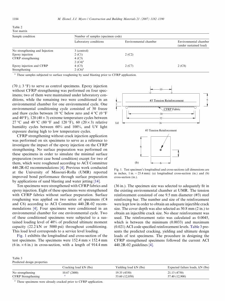
Table 2Test matrix
Sample condition Number of samples (specimen code)
Laboratory conditions Environmental chamber Environmental chamber(under sustained load)
No strengthening and Injection 3 (control)Epoxy injection 2 (C1) 2 (C2)CFRP strengthening 4 (C3)
2 (C4)a
Epoxy injection and CFRP 4 (C5) 2 (C7) 2 (C8)Strengthening 2 (C6)a
a These samples subjected to surface roughening by sand blasting prior to CFRP application.
30
32
36
2#3 Tension Reinforcement
10
CFRP Fabric
6
(a)
#3 Tension Reinforcement
6
2
6(b)
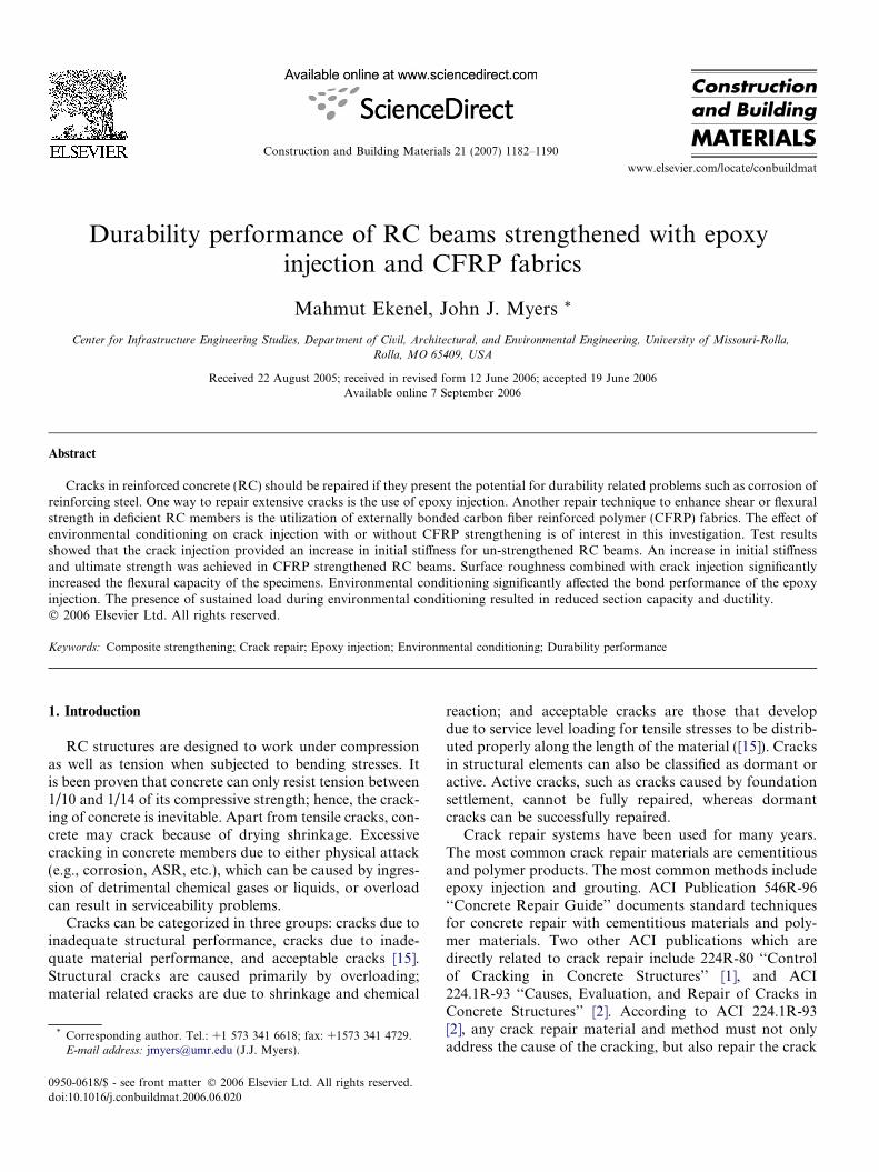
Fig. 1. Test specimen’s longitudinal and cross-sections (all dimensions arein inches, 1 in. = 25.4 mm): (a) longitudinal cross-section (in.) and (b)cross-section (in.).
1184 M. Ekenel, J.J. Myers / Construction and Building Materials 21 (2007) 1182–1190
(70 ± 3 �F) to serve as control specimens. Epoxy injectionwithout CFRP strengthening was performed on four spec-imens; two of them were maintained under laboratory con-ditions, while the remaining two were conditioned in anenvironmental chamber for one environmental cycle. Oneenvironmental conditioning cycle consisted of 50 freezeand thaw cycles between 18 �C below zero and 4 �C (0 �Fand 40�F), 120 (40 · 3) extreme temperature cycles between27 �C and 49 �C (80 �F and 120 �F), 60 (20 · 3) relativehumidity cycles between 60% and 100%, and UV lightexposure during high to low temperature cycles.
CFRP strengthening without crack injection applicationwas performed on six specimens to serve as a reference toinvestigate the impact of the epoxy injection on the CFRPstrengthening. No surface preparation was performed onthese specimens in order to simulate the minimal surfacepreparation (worst case bond condition) except for two ofthem, which were roughened according to ACI Committee440.2R-02 recommendations [4]. Previous work conductedat the University of Missouri-Rolla (UMR) reportedimproved bond performance through surface preparationby applications of sand blasting and water jetting [14].
Ten specimens were strengthened with CFRP fabrics andepoxy injection. Eight of these specimens were strengthenedwith CFRP fabrics without surface preparation. Surfaceroughening was applied on two series of specimens (C4and C6) according to ACI Committee 440.2R-02 recom-mendations [4]. Four specimens were conditioned in anenvironmental chamber for one environmental cycle. Twoof these conditioned specimens were subjected to a sus-tained loading level of 40% of predicted ultimate momentcapacity (22.2 kN or 5000 psi) throughout conditioning.This load level corresponds to a service level loading.
Fig. 1 exhibits the longitudinal and cross-section of thetest specimens. The specimens were 152.4 mm · 152.4 mm(6 in. · 6 in.) in cross-section, with a length of 914.4 mm
Table 3Predicted design properties
Cracking load kN (lbs)
No strengthening 10.67 (2400)CFRP Strengthening a
a These specimens were already cracked prior to CFRP application.
(36 in.). The specimen size was selected to adequately fit inthe existing environmental chamber at UMR. The tensionreinforcement consisted of one 9.5 mm diameter (#3) steelreinforcing bar. The number and size of the reinforcementwere kept low in order to obtain an adequate injectible cracksize. The cover depth was also selected as 50.8 mm (2 in.) toobtain an injectible crack size. No shear reinforcement wasused. The reinforcement ratio was calculated as 0.0045,which is between the minimum (0.0033) and maximum(0.021) ACI code specified reinforcement levels. Table 3 pre-sents the predicted cracking, yielding and ultimate designloads of test specimens. The procedure in designing theCFRP strengthened specimens followed the current ACI440.2R-02 guidelines [4].
Yielding load kN (lbs) Expected failure loads, kN (lbs)
19.35 (4350) 21.13 (4750)53.60 (12,050) 57.40 (12,900)
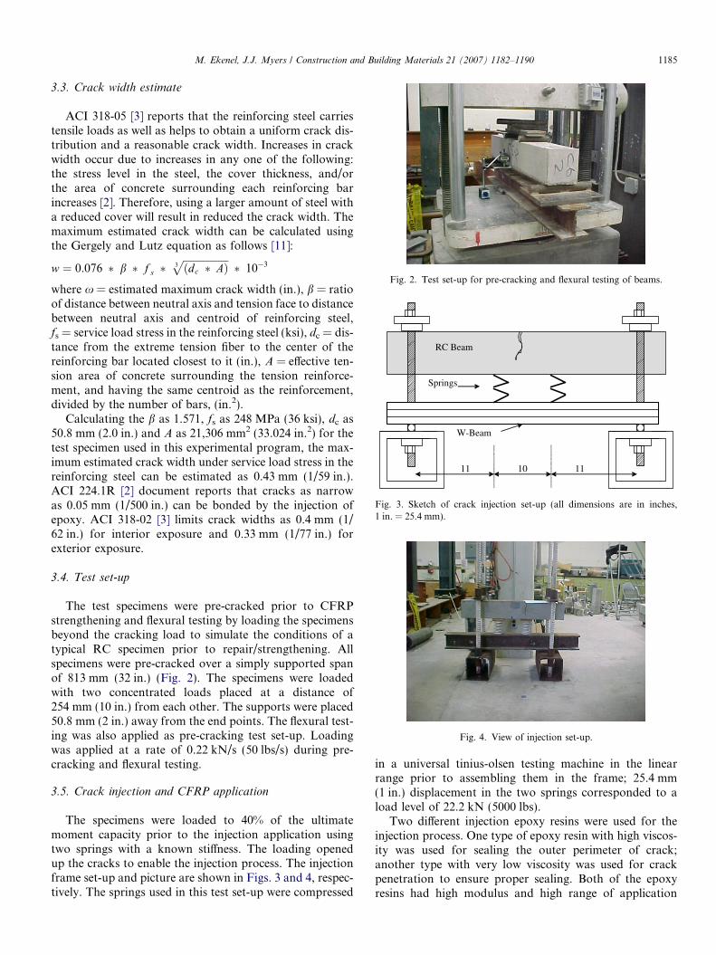
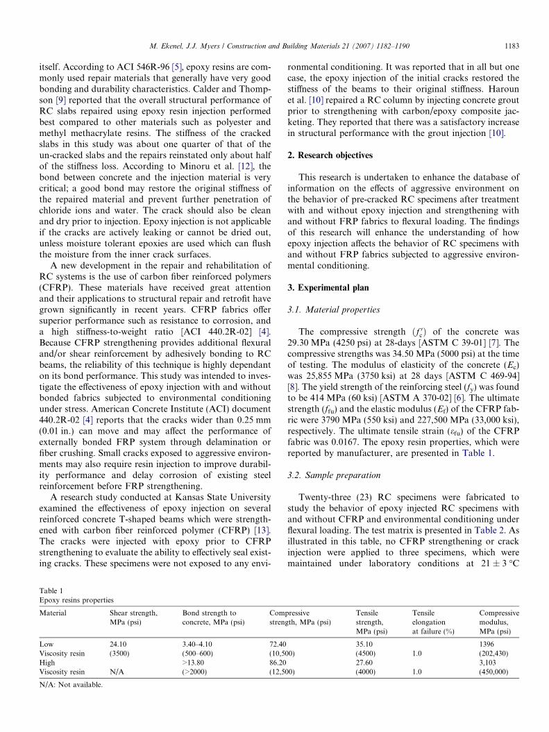
Fig. 2. Test set-up for pre-cracking and flexural testing of beams.
1011 11
W-Beam
Springs
RC Beam
Fig. 3. Sketch of crack injection set-up (all dimensions are in inches,1 in. = 25.4 mm).
Fig. 4. View of injection set-up.
M. Ekenel, J.J. Myers / Construction and Building Materials 21 (2007) 1182–1190 1185
3.3. Crack width estimate
ACI 318-05 [3] reports that the reinforcing steel carriestensile loads as well as helps to obtain a uniform crack dis-tribution and a reasonable crack width. Increases in crackwidth occur due to increases in any one of the following:the stress level in the steel, the cover thickness, and/orthe area of concrete surrounding each reinforcing barincreases [2]. Therefore, using a larger amount of steel witha reduced cover will result in reduced the crack width. Themaximum estimated crack width can be calculated usingthe Gergely and Lutz equation as follows [11]:
w ¼ 0:076 � b � f s �ffiffiffiffiffiffiffiffiffiffiffiffiffiffiffiffiffiffiðdc � AÞ3
p� 10�3
where x = estimated maximum crack width (in.), b = ratioof distance between neutral axis and tension face to distancebetween neutral axis and centroid of reinforcing steel,fs = service load stress in the reinforcing steel (ksi), dc = dis-tance from the extreme tension fiber to the center of thereinforcing bar located closest to it (in.), A = effective ten-sion area of concrete surrounding the tension reinforce-ment, and having the same centroid as the reinforcement,divided by the number of bars, (in.2).
Calculating the b as 1.571, fs as 248 MPa (36 ksi), dc as50.8 mm (2.0 in.) and A as 21,306 mm2 (33.024 in.2) for thetest specimen used in this experimental program, the max-imum estimated crack width under service load stress in thereinforcing steel can be estimated as 0.43 mm (1/59 in.).ACI 224.1R [2] document reports that cracks as narrowas 0.05 mm (1/500 in.) can be bonded by the injection ofepoxy. ACI 318-02 [3] limits crack widths as 0.4 mm (1/62 in.) for interior exposure and 0.33 mm (1/77 in.) forexterior exposure.
3.4. Test set-up
The test specimens were pre-cracked prior to CFRPstrengthening and flexural testing by loading the specimensbeyond the cracking load to simulate the conditions of atypical RC specimen prior to repair/strengthening. Allspecimens were pre-cracked over a simply supported spanof 813 mm (32 in.) (Fig. 2). The specimens were loadedwith two concentrated loads placed at a distance of254 mm (10 in.) from each other. The supports were placed50.8 mm (2 in.) away from the end points. The flexural test-ing was also applied as pre-cracking test set-up. Loadingwas applied at a rate of 0.22 kN/s (50 lbs/s) during pre-cracking and flexural testing.
3.5. Crack injection and CFRP application
The specimens were loaded to 40% of the ultimatemoment capacity prior to the injection application usingtwo springs with a known stiffness. The loading openedup the cracks to enable the injection process. The injectionframe set-up and picture are shown in Figs. 3 and 4, respec-tively. The springs used in this test set-up were compressed
in a universal tinius-olsen testing machine in the linearrange prior to assembling them in the frame; 25.4 mm(1 in.) displacement in the two springs corresponded to aload level of 22.2 kN (5000 lbs).
Two different injection epoxy resins were used for theinjection process. One type of epoxy resin with high viscos-ity was used for sealing the outer perimeter of crack;another type with very low viscosity was used for crackpenetration to ensure proper sealing. Both of the epoxyresins had high modulus and high range of application

1186 M. Ekenel, J.J. Myers / Construction and Building Materials 21 (2007) 1182–1190
temperatures of 1.7 �C and 43.3 �C (35–110 �F). They werealso moisture insensitive. The mechanical properties ofepoxy resins were previously presented in Table 1 asreported by the manufacturer.
Initially, crack widths were determined by using a non-destructive crack inspection device (crack comparator) asillustrated in Fig. 5. The crack comparator was a small,hand-held microscope with a scale in millimeters on thelens. The crack measurements of all specimens were in arange from 0.38 mm (1/66 in.) to 0.86 mm (1/30 in.). Thefollowing steps were taken for epoxy injection and CFRPapplication:
� The first step was placement of specimen on the test set-up as upside down position and load up to service loadlevels via springs so the cracks open up (Fig. 4);� Cracks were cleaned using a wire brush, pressurized air,
and vacuum in order to remove dirt which may preventepoxy penetration and adhesion;� The ports were mounted on the crack at a spacing
approximately the same as the thickness (depth) of thecracked member (Fig. 6). The method used for affixingthe ports was placing a small amount of epoxy pasteat the feet of the port and sticking it over the crack.Extra care was taken not to plug the port by epoxy pastewhich may prevent or limit injection material to passthrough;
Fig. 5. Crack comparator.
Fig. 6. Epoxy injection.
� The crack surfaces were sealed using a high viscosityepoxy to prevent the injection epoxy from leaking outprior to set. Twenty-four hours cure time was used(Fig. 6);� Cracks were injected via ports by using an air-actuated
pump. First, the top port was used for injecting low vis-cosity epoxy and this continued until the injection epoxystarted leaking out from side ports. Finally the portswere plugged. A cure time of 48 h was used as per man-ufacturers recommendation;� After the injected epoxy had cured, the load was
released and the specimen was removed from injectionset-up. Finally, the surface seal was removed by grinding(Fig. 7);� Following the grinding process, the CFRP strengthening
was applied on ten crack-injected samples according tothe test matrix (Table 2). Surface preparation was per-formed on two out of ten specimens according to ACI440.2R-02 [4]. The width of the CFRP sheets wasselected as 76.2 mm (3 in.) in order to yield a desiredductile failure by steel yielding followed by concretecrushing. The CFRP sheets were applied over 762 mm(30 in.) of the span length;� Four of the specimens were moved into an environmen-
tal chamber for one environmental cycle. Two of thesespecimens were maintained under sustained loading of40% of the predicted ultimate moment capacity of thespecimens. The specimens were stacked one above theother and two springs were placed between two speci-mens to maintain the load during environmental condi-tioning in chamber.
4. Experimental results
4.1. Specimens without CFRP strengthening
Three control and two crack-injected samples were testedunder flexural loading. These samples did not include CFRPstrengthening. The mid-span displacement and correspond-ing load reading were monitored via a data acquisition sys-tem (DAS). Load versus mid-span displacement readings
Fig. 7. Grinding the epoxy seal.
M. Ekenel, J.J. Myers / Construction and Building Materials 21 (2007) 1182–1190 1187
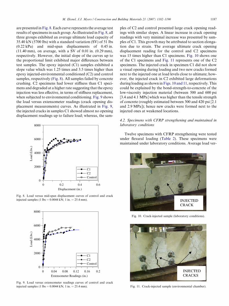
are presented in Fig. 8. Each curve represents the average testresults of specimens in each group. As illustrated in Fig. 8, allthree groups exhibited an average ultimate load capacity of35.40 kN (5700 lbs) with a standard variation (SV) of 51 lbs(0.22 kPa) and mid-span displacements of 0.45 in.(11.40 mm), on average, with a SV of 0.01 in. (0.29 mm),respectively. However, the initial slope of the curves up tothe proportional limit exhibited major differences betweentest samples. The epoxy injected (C1) samples exhibited aslope value which was 1.25 times and 3.5 times higher thanepoxy injected-environmental conditioned (C2) and controlsamples, respectively (Fig. 8). All samples failed by concretecrushing. C2 specimens had lower stiffness than C1 speci-mens and degraded at a higher rate suggesting that the epoxyinjection was less effective, in terms of stiffness replacement,when subjected to environmental conditioning. Fig. 9 showsthe load versus extensometer readings (crack opening dis-placement measurements) curves. As illustrated in Fig. 9,the injected cracks in samples C1 showed almost no openingdisplacement readings up to failure load; whereas, the sam-
0 0.2 0.4 0.6
Displacement (in.)
0
2000
4000
6000
8000
Loa
d (L
bs.)
C1C2Control
Fig. 8. Load versus mid-span displacement curves of control and crackinjected samples (1 lbs = 0.0044 kN; 1 in. = 25.4 mm).
0 0.04 0.08 0.12 0.16 0.2
Extensometer Readings (in.)
0
2000
4000
6000
8000
Loa
d (L
bs.)
C1C2Control
Fig. 9. Load versus extensometer readings curves of control and crackinjected samples (1 lbs = 0.0044 kN; 1 in. = 25.4 mm).
ples of C2 and control presented large crack opening read-ings with similar slopes. A linear increase in crack openingreadings with very minimal increase was presented by sam-ples of C1. This growth may be attributed to section elonga-tion due to strain. The average ultimate crack openingdisplacement reading for the control and C2 specimenswas 15 times higher than C1 specimens. Fig. 10 shows oneof the C1 specimens and Fig. 11 represents one of the C2specimens. The injected crack in specimen C1 did not showa visual opening during loading and two new cracks formednext to the injected one at load levels close to ultimate; how-ever, the injected crack in C2 exhibited large deformationsduring loading as shown in Figs. 10 and 11, respectively. Thiscould be explained by the bond-strength-to-concrete of thelow-viscosity injection material (between 500 and 600 psi[3.4 and 4.1 MPa] which was higher than the tensile strengthof concrete (roughly estimated between 300 and 420 psi [2.1and 2.9 MPa]); hence new cracks were formed next to theinjected ones at weakened locations.
4.2. Specimens with CFRP strengthening and maintained in
laboratory conditions
Twelve specimens with CFRP strengthening were testedunder flexural loading (Table 2). These specimens weremaintained under laboratory conditions. Average load ver-
Fig. 10. Crack-injected sample (laboratory conditions).
Fig. 11. Crack-injected sample (environmental chamber).

1188 M. Ekenel, J.J. Myers / Construction and Building Materials 21 (2007) 1182–1190
sus mid-span displacement readings for all specimens testedin this grouping are presented in Fig. 12. As illustrated inFig. 12, the surface roughened specimens with crack injec-tion (C6) exhibited higher ultimate strength and deflectionas compared to the non-surface roughened non-injectionspecimens (C3), surface roughened non-injection specimens(C4), and non-surface roughened injected specimens (C5).Specimen C6 exhibited a failure load and standard devia-tion of 62.72 and 3.7 kN (14,100 and 826 lbs), on average.These load values correlate to the predicted design load of57.40 kN (12,900 lbs) However, C3 and C5 specimensexhibited lower failure loads. C3 exhibited an average fail-ure load and SV of 46.70 and 2.80 kN (10,500 and 636 lbs);C5 exhibited an average failure load and SV of 52.0 and9.3 kN (11,700 and 2092 lbs). The initial slope of the curvesup to the proportional limit exhibited differences betweentest samples. The C6 samples exhibited a slope value which
0 0.1 0.2 0.3 0.4Displacement (in.)
0
4000
8000
12000
16000
Loa
d (L
bs.)
C3C4C5C6
Fig. 12. Load versus displacement curves of CFRP strengthened samples(1 lbs = 0.0044 kN; 1 in. = 25.4 mm).
Fig. 13. Specimens after failure: (a) non-surfa
is 1.27, 1.46, and 2.15 times higher than C5, C4, and C3,respectively (Fig. 12). Specimens with crack injectionexhibited higher initial stiffness than their counterpart spec-imens without injection as the epoxy injection helped to‘‘restore’’ their initial pre-cracked stiffness. All CFRP fab-ric applied samples failed by concrete crushing followed bya complete CFRP delamination. After further examinationof the failed specimens, it was observed that the surfaceroughened specimens (C4 and C6) appeared to debond inthe substrate region while the non-surface preparationapplied specimens (C3 and C5) debonded at the FRP-con-crete interface (Fig. 13). Fig. 14 illustrates the load versusextensometer readings (crack opening displacement mea-surements) curves. As illustrated in Fig. 14, C6 specimensdid not show any crack opening displacement readings atthe lower load levels and slightly higher opening readingsat the levels close to ultimate load; whereas specimens ofC3, C4, and C5 presented large crack opening readingswhich started soon after initial loading. Fig. 15 showsone of the CFRP strengthened specimens and Fig. 16 rep-resents one of the CFRP strengthened and crack injectedspecimens. The crack injected specimen did not show avisual opening during loading and a new crack formed nextto injected one (Fig. 16); however, the specimen withoutcrack injection exhibited large deformations during loading(Fig. 15). It can be clearly interpreted from the data pre-sented that the injection aids in limiting crack opening;moreover, injection with surface roughening is the best casescenario for structural repair.
4.3. Specimens with CFRP strengthening maintained in an
environmental chamber
Fig. 17 shows the load versus mid-span displacementcurves of the CFRP strengthened and crack injected spec-imens C7 and C8. These specimens were maintained in
ce roughened and (b) surface roughened.
0 0.01 0.02 0.03Extensometer Readings (in.)
0
4000
8000
12000
16000L
oad
(Lbs
.)
C3C4C5C6
Fig. 14. Load versus extensometer readings curves of CFRP strengthenedsamples (1 lbs = 0.0044 kN; 1 in. = 25.4 mm).
Fig. 15. CFRP strengthened sample (laboratory conditions).
Fig. 16. CFRP strengthened and crack-injected sample (laboratoryconditions).
0 0.1 0.2 0.3 0.4
Displacement (in.)
0
4000
8000
12000
16000
Loa
d (L
bs.)
C7C8
Fig. 17. Load versus displacement curves of CFRP strengthened samples(environmental conditions) (1 lbs = 0.0044 kN; 1 in. = 25.4 mm).
0 0.01 0.02 0.03Extensometer Readings (in.)
0
4000
8000
12000
16000
Loa
d (L
bs.)
C7C8
Fig. 18. Load versus extensometer readings curves of CFRP strengthenedsamples (environmental conditions) (1 lbs = 0.0044 kN; 1 in. = 25.4 mm).
M. Ekenel, J.J. Myers / Construction and Building Materials 21 (2007) 1182–1190 1189
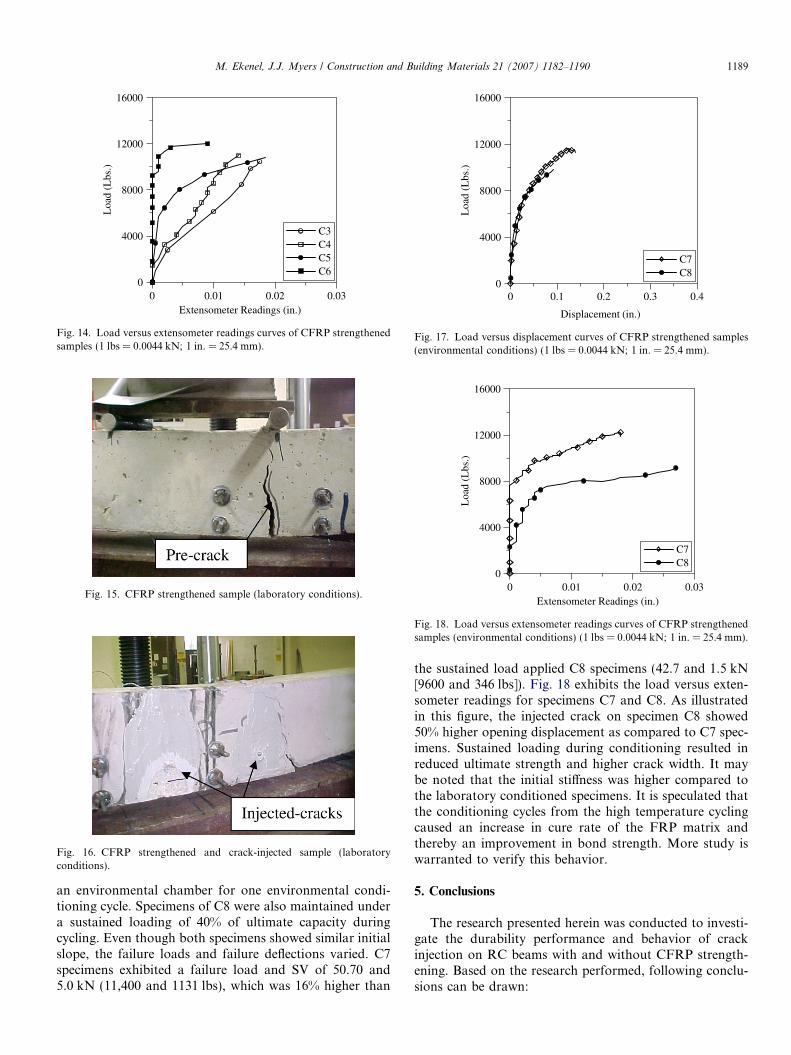
an environmental chamber for one environmental condi-tioning cycle. Specimens of C8 were also maintained undera sustained loading of 40% of ultimate capacity duringcycling. Even though both specimens showed similar initialslope, the failure loads and failure deflections varied. C7specimens exhibited a failure load and SV of 50.70 and5.0 kN (11,400 and 1131 lbs), which was 16% higher than
the sustained load applied C8 specimens (42.7 and 1.5 kN[9600 and 346 lbs]). Fig. 18 exhibits the load versus exten-someter readings for specimens C7 and C8. As illustratedin this figure, the injected crack on specimen C8 showed50% higher opening displacement as compared to C7 spec-imens. Sustained loading during conditioning resulted inreduced ultimate strength and higher crack width. It maybe noted that the initial stiffness was higher compared tothe laboratory conditioned specimens. It is speculated thatthe conditioning cycles from the high temperature cyclingcaused an increase in cure rate of the FRP matrix andthereby an improvement in bond strength. More study iswarranted to verify this behavior.
5. Conclusions
The research presented herein was conducted to investi-gate the durability performance and behavior of crackinjection on RC beams with and without CFRP strength-ening. Based on the research performed, following conclu-sions can be drawn:
1190 M. Ekenel, J.J. Myers / Construction and Building Materials 21 (2007) 1182–1190
� Crack injection provided an increase in stiffness in thelinear region of the load–displacement curves for all ofthe RC beams without CFRP strengthening; theincrease was as high as 3.5 times the control specimens.However, no increase in flexural capacity was observed;� The control samples under laboratory conditions and
injected specimens under environmental conditioning(C2) showed crack opening displacements significantlyhigher (15% more) than injected specimens under labora-tory conditions (C1). The injected cracks for specimenC1 showed insignificant linear opening readings. Mini-mal opening readings were attributed to section elonga-tion due to strain. However, new small cracks formedaround the injected ones. The higher crack opening read-ings and reformation of cracks at injected locationsexhibited by specimen C2 suggest that the epoxy injec-tion is less effective when subjected to environmentalconditioning;� An increase in ultimate strength and initial stiffness of
load versus deflection curves is achieved by CFRPstrengthened RC specimens with crack injection as com-pared to CFRP strengthened specimens without crackinjection. Injected cracks in CFRP strengthened speci-mens showed minimal crack opening displacement; spec-imens without crack injection showed crack openingdisplacements to some extend but not as high as theun-strengthened samples. This can be explained byCFRP application, which caused a reduction of stressin the reinforcement steel and reduced crack propaga-tion. Hence crack injection prior to CFRP strengtheningis recommended in cases where severe cracking hasoccurred and durability is a major concern;� Surface roughness combined with crack injection
increased the flexural capacity of specimens significantlyand reduced the crack width opening as compared toother CFRP strengthened specimens;� Environmental conditioning and sustained loading sig-
nificantly affected the ultimate strength (16% lower)and crack width (50% higher) of specimens (C8) as com-pared to environmental conditioned specimens (C7).Even though environmentally conditioned specimens(C7) and laboratory conditioned specimens (C5) exhib-ited very close ultimate loads and crack opening dis-placements, C8 specimens exhibited 18% lower failureload and 50% higher crack opening readings as com-pared to C5 at ultimate loads.
Acknowledgements
The authors wish to express their gratitude and sincereappreciation to the authority of Federal Highway Admin-istration (FHwA) and Center for Infrastructure Engineer-ing Studies (CIES) at the University of Missouri-Rollafor supporting this research study. The authors would alsolike to acknowledge Mr. Nathan Marshall for his effort onthis project as an undergraduate research assistant.
References
[1] ACI Committee 224R-80. Control of cracking in concrete structures.MI: American Concrete Institute; 1980.
[2] ACI Committee 224.1R-93. Causes, evaluation, and repair of cracksin concrete structures. MI: American Concrete Institute; 1993.
[3] ACI Committee 318-05. Building code requirements for structuralconcrete and commentary. Farmington Hills, MI: American ConcreteInstitute; 2005.
[4] ACI Committee 440.2R-02. Guide for the design and construction ofexternally bonded FRP systems for strengthening concrete structures.Michigan: American Concrete Institute; 2002.
[5] ACI Committee 546R-96. Concrete repair guide. Michigan: AmericanConcrete Institute; 1996.
[6] ASTM A370. Standard test methods and definitions for mechanicaltesting of steel products. 2002; vol. 04-02, Philadelphia, PA.
[7] ASTM C 39. Standard test method for compressive strength ofcylindrical concrete specimens. 2001; vol. 04-02, Philadelphia, PA.
[8] ASTM C 469. Standard test method for static modulus of elasticityand poisson’s ratio of concrete in compression. 1994; vol. 04-02,Philadelphia, PA.
[9] Calder A.J.J., Thompson DM. Repair of cracked reinforced concrete:assessment of corrosion protection. Transport and Road ResearchLaboratory, Department of Transport, Research Report 150, 1998.
[10] Haroun MA, Mosallam AS, Feng MQ, Elsanadedy HM. Experi-mental investigation of seismic repair and retrofit of bridge columnsby composite jackets. J Reinf Plast Compos 2003;22(14):1243–68.
[11] Macgregor JG. Reinforced concrete mechanics and design. Third ed.New Jersey: Prentice-Hall Inc.; 1997.
[12] Minoru K, Toshiro K, Yuichi U, Keitetsu R. Evaluation of bondproperties in concrete repair materials. J Mater Civ Eng 2001;13(2):98–105.
[13] Reed CE, Peterman RJ, Rasheed H, and Meggers D. Adhesiveapplications used during the repair and strengthening of 30-year-oldPrestressed concrete girders (input to TRB). Transportation ResearchBoard Annual Meeting CD-ROM, 2003.
[14] Shen X., Myers J.J., Maerz N., and Galecki G. Effect of roughness onthe bond performance between FRP laminates and concrete.Proceedings of CDCC, 2002, Montreal.
[15] Tsiatas, G., Robinson, J., Durability evaluation of concrete crackrepair systems. Transportation Research Record 1795, 1994, PaperNo 02-3596, p. 82–7.