dual differential pressure sensor for ventilation and air
TRANSCRIPT

Pressure
for further approvals see page 5
Dual differential pressure sensor For ventilation and air-conditioningModel A2G-52
Dual differential pressure sensor, model A2G-52
Applications
■ For monitoring air, non-inflammable and non-aggressive gases
■ Fan, blower and filter monitoring ■ Pressure and flow monitoring ■ Monitoring and control of valves and air shutters ■ Pressure monitoring in clean rooms
Special features
■ Simple mounting ■ Two differential pressure sensors in one instrument ■ Two inputs for temperature sensors or analogue signal ■ With Modbus® interface ■ Two-line LC display for the direct reading of both pressure
values
WIKA data sheet PE 88.03
WIKA data sheet PE 88.03 ∙ 10/2019 Page 1 of 5
Description
The model A2G-52 dual differential pressure sensor combines two differential pressure sensors in one instrument, so that pressure can be measured from two different control points.
The model A2G-52 has a Modbus interface and an input interface. By using the input interface, up to two passive temperature sensors or an analogue 0 ... 10 V signal can be connected directly to the measuring instrument. Thus, the use of cost-intensive active temperature transmitters can be dispensed with and the costs for material and mounting can be reduced.

Page 2 of 5WIKA data sheet PE 88.03 ∙ 10/2019
Specifications
Modbus® communicationProtocol Modbus® via serial interfaceTransfer mode RTUInterface RS-485Byte format (11 bits) in RTU mode
Coding system: 8 bits binary
Bits per byte:- 1 Start bit- 8 data bits, lowest-order bit is sent first- 1 bit for parity- 1 stop bit
Baud rate 9,600, 19,200, 38,400 - adjustable in the configurationModbus® addresses 1 ... 247 addresses - adjustable in the configuration
Dual differential pressure sensor, model A2G-52Measuring element Piezo measuring cellUnits of measure Pa, mbar, inWC, mmWC, psiMeasuring range -250 … +2,500 Pa and -250 … +7,500 PaAccuracy class -250 ... +2,500 Pa = pressure < 125 Pa = ±2 Pa + 1 %
pressure > 125 Pa = ±1 Pa + 1 %
-250 ... +7,000 Pa = pressure < 125 Pa = ±2 Pa + 1.5 %pressure > 125 Pa = ±1 Pa + 1.5 %
all data refer to the current measured value (of measured pressure)Process connection Connecting nozzle (copper alloy), lower mount, for hoses with inner diameter 4 mmPower supply UB AC 24 V or DC 24 V ±10 %Electrical connection Cable gland M20
2 x 4 spring-clip terminals, max. 1.5 mm2
Output signal Modbus®
Display Two-line LC display (12 characters/line)Line 1: Active measurement, input ALine 2: Active measurement, input B
Case Plastic (ABS)Cover: Polycarbonate (PC)
Permissible temperatures ■ Ambient temperature ■ Medium temperature
-20 ... +70 °C-10 ... +50 °C
Relative humidity 0 … 95 % r. h., non-condensingIngress protection IP54Weight 150 g
Options ■ 4 duct connectors ■ 4 m PVC hose, inner diameter 4 mm
Pt1000 J1
IN1
J2
J3
NTC10k IN2
Pt1000 J1
IN1
J2
J3
NTC10k IN2
Page 3 of 5WIKA data sheet PE 88.03 ∙ 10/2019
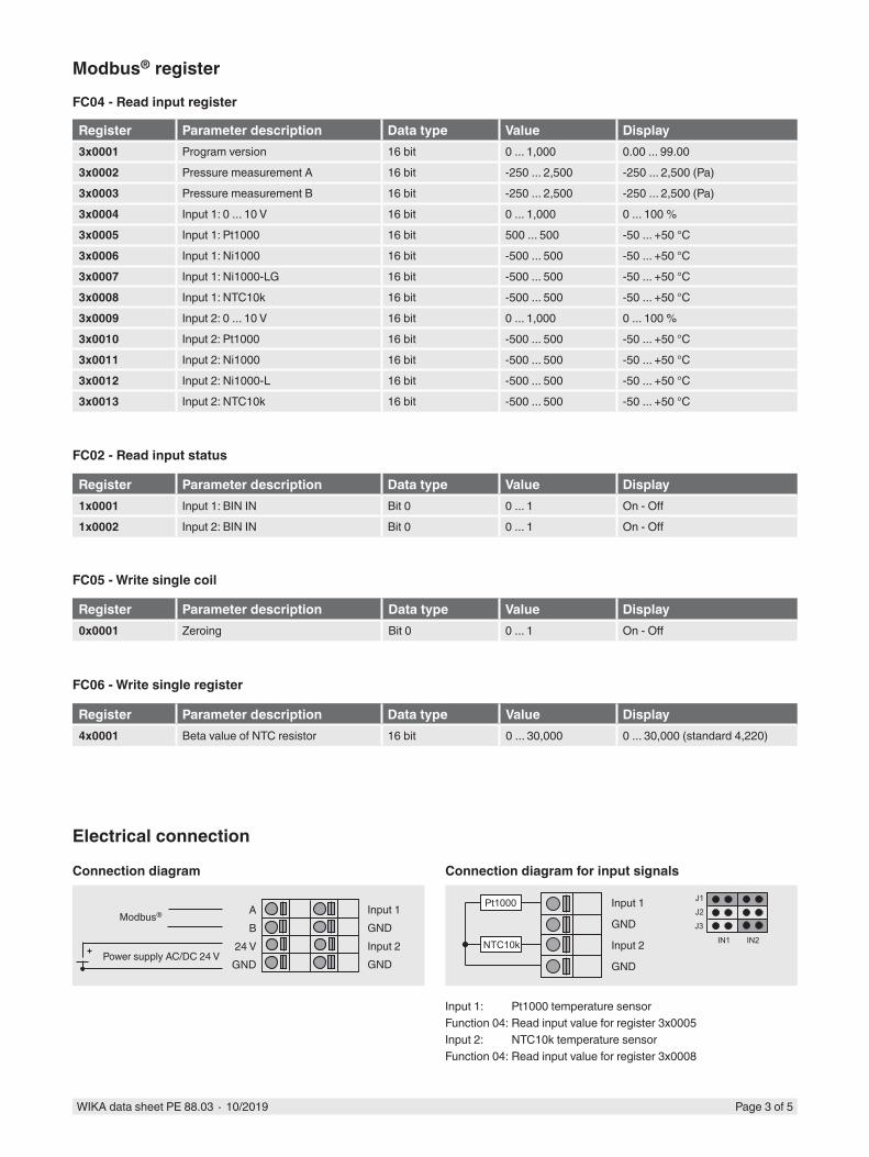
Register Parameter description Data type Value Display3x0001 Program version 16 bit 0 ... 1,000 0.00 ... 99.003x0002 Pressure measurement A 16 bit -250 ... 2,500 -250 ... 2,500 (Pa)3x0003 Pressure measurement B 16 bit -250 ... 2,500 -250 ... 2,500 (Pa)3x0004 Input 1: 0 ... 10 V 16 bit 0 ... 1,000 0 ... 100 %3x0005 Input 1: Pt1000 16 bit 500 ... 500 -50 ... +50 °C3x0006 Input 1: Ni1000 16 bit -500 ... 500 -50 ... +50 °C3x0007 Input 1: Ni1000-LG 16 bit -500 ... 500 -50 ... +50 °C3x0008 Input 1: NTC10k 16 bit -500 ... 500 -50 ... +50 °C3x0009 Input 2: 0 ... 10 V 16 bit 0 ... 1,000 0 ... 100 %3x0010 Input 2: Pt1000 16 bit -500 ... 500 -50 ... +50 °C3x0011 Input 2: Ni1000 16 bit -500 ... 500 -50 ... +50 °C3x0012 Input 2: Ni1000-L 16 bit -500 ... 500 -50 ... +50 °C3x0013 Input 2: NTC10k 16 bit -500 ... 500 -50 ... +50 °C
Modbus register
FC04 - Read input register
Register Parameter description Data type Value Display1x0001 Input 1: BIN IN Bit 0 0 ... 1 On - Off1x0002 Input 2: BIN IN Bit 0 0 ... 1 On - Off
FC02 - Read input status
Register Parameter description Data type Value Display0x0001 Zeroing Bit 0 0 ... 1 On - Off
FC05 - Write single coil
Register Parameter description Data type Value Display4x0001 Beta value of NTC resistor 16 bit 0 ... 30,000 0 ... 30,000 (standard 4,220)
FC06 - Write single register
Electrical connection
Input 1GNDInput 2GND
Input 1
GND
Input 2
GNDPower supply AC/DC 24 V
AB
24 VGND
Connection diagram Connection diagram for input signals
Modbus®
Input 1: Pt1000 temperature sensorFunction 04: Read input value for register 3x0005Input 2: NTC10k temperature sensorFunction 04: Read input value for register 3x0008

Description Order numberA2G-52 with measuring range -250 ... +2,500 Pa 40399907A2G-52 with measuring range -250 ... +7,000 Pa 40399920
Page 4 of 5WIKA data sheet PE 88.03 ∙ 10/2019
Accessories
Description Order numberMeasuring hoses
PVC hose, inner diameter 4 mm, roll at 25 m 40217841PVC hose, inner diameter 6 mm, roll at 25 m 40217850Silicone hose, inner diameter 4 mm, roll at 25 m 40208940Silicone hose, inner diameter 6 mm, roll at 25 m 40208958
Duct connector for hose 4 and 6 mm 40217507
Dimensions in mm

© 04/2015 WIKA Alexander Wiegand SE & Co. KG, all rights reserved.The specifications given in this document represent the state of engineering at the time of publishing.We reserve the right to make modifications to the specifications and materials.
Ordering informationTo order the described product the order number is sufficient.orModel / Measuring range / Input signal / Accessories / Options
WIKA Alexander Wiegand SE & Co. KGAlexander-Wiegand-Straße 3063911 Klingenberg/GermanyTel. +49 9372 132-0Fax +49 9372 [email protected]
10/2
019
EN Page 5 of 5WIKA data sheet PE 88.03 ∙ 10/2019
Approvals
Logo Description CountryEU declaration of conformity
■ EMC directive ■ RoHS conformity ■ WEEE directive
European Union
EAC (option) ■ EMC directive ■ Import certificate
Eurasian Economic Community
GOST (option)Metrology, measurement technology
Russia
- MTSCHS (option)Permission for commissioning
Kazakhstan
Certificates (option)2.2 test report
Approvals and certificates, see website
Scope of delivery ■ Dual differential pressure sensor ■ 2 mounting screws